JP5113919B2 - Inspection drive diagnosis method for inverter drive motor - Google Patents
Inspection drive diagnosis method for inverter drive motor Download PDFInfo
- Publication number
- JP5113919B2 JP5113919B2 JP2011042274A JP2011042274A JP5113919B2 JP 5113919 B2 JP5113919 B2 JP 5113919B2 JP 2011042274 A JP2011042274 A JP 2011042274A JP 2011042274 A JP2011042274 A JP 2011042274A JP 5113919 B2 JP5113919 B2 JP 5113919B2
- Authority
- JP
- Japan
- Prior art keywords
- voltage
- insulation
- motor
- partial discharge
- inverter
- Prior art date
- Legal status (The legal status is an assumption and is not a legal conclusion. Google has not performed a legal analysis and makes no representation as to the accuracy of the status listed.)
- Expired - Fee Related
Links
Images


Description
本発明は、インバータ駆動モータの検査診断方法に関する。 The present invention relates to an inspection diagnosis method for an inverter drive motor.
近年、省エネルギー及び高効率化の観点から、インバータ電源を用いてモータを可変速運転することが盛んに行われている。ところで、インバータ電源からモータに印加される電圧はパルス電圧(以下、インバータパルス電圧という。)であるから、モータ絶縁材料の絶縁性能の評価はパルス電圧を考慮する必要がある。 In recent years, from the viewpoint of energy saving and high efficiency, it has been actively practiced to operate a motor at a variable speed using an inverter power supply. By the way, since the voltage applied to the motor from the inverter power supply is a pulse voltage (hereinafter referred to as inverter pulse voltage), the evaluation of the insulation performance of the motor insulating material needs to consider the pulse voltage.
しかし、正弦波に対するモータ絶縁材料の絶縁評価データ、設計方法、検査方法、診断方法は確立されているが、インバータパルス電圧に対する絶縁評価データ、設計方法、検査方法、診断方法は必ずしも確立されておらず、現在、様々な分野によって鋭意検討がなされている。例えば、非特許文献1に、インバータパルス電圧下における絶縁材料の部分放電特性の評価が紹介されている。
However, although the insulation evaluation data, design method, inspection method, and diagnosis method for motor insulation materials for sine waves have been established, the insulation evaluation data, design method, inspection method, and diagnosis method for inverter pulse voltage have not necessarily been established. At present, intensive studies are being conducted in various fields. For example, Non-Patent
また、特許文献1には、従来から蓄積されてきた正弦波の絶縁寿命データをベースとして、インバータパルス電圧下の絶縁材料の寿命を推定する方法が提案されている。これによれば、インバータパルス電圧に伴う絶縁劣化は、パルス電圧の立ち上がり時間が最も重要な電圧パラメータであると考えている。また、インバータパルス電圧の立ち上がり時間は正弦波電圧に比べて短いため、部分放電開始電圧が増加し、部分放電開始電圧の増加分だけ正弦波に比べて絶縁物の寿命特性が高電圧側にシフトすると考えている。
しかし、インバータパルス電圧に対する絶縁性能を評価するにあたって、インバータパルス電圧の立ち上がり時間以外に、インバータパルス電圧の立下り時間、パルス幅、単極性/両極性、極性反転の有無、周波数などの種々の電圧パラメータが関係してくる。それにもかかわらず、従来の絶縁評価では、電圧パラメータが個々の検討毎に異なっているため、どの電圧パラメータが部分放電特性に影響しているのか必ずしも明確ではなく、かつ実際の製品にどのように適用してよいかも不明確であった。そのため、従来の測定結果を、必ずしも直ちにインバータ駆動モータの絶縁設計、検査、診断に反映することができなかった。 However, in evaluating the insulation performance against the inverter pulse voltage, in addition to the rise time of the inverter pulse voltage, various voltages such as the fall time of the inverter pulse voltage, pulse width, unipolar / bipolar, presence / absence of polarity reversal, frequency, etc. Parameters are relevant. Nonetheless, in conventional insulation evaluation, the voltage parameters are different for each study, so it is not always clear which voltage parameters affect the partial discharge characteristics, and how it is applied to actual products. It was unclear whether it could be applied. For this reason, the conventional measurement results cannot always be immediately reflected in the insulation design, inspection, and diagnosis of the inverter drive motor.
仮に、電圧パラメータの中からインバータパルス電圧に起因する絶縁劣化において、最も影響が大きいと考えられる電圧パラメータを1つもしくは複数仮定し、絶縁材料やモータの絶縁特性、とりわけ絶縁材料やモータの寿命を計測するとすれば、長期間の試験時間が必要となり、近年普及が著しいインバータ駆動モータの設計等に適用するのは困難である。 Assuming one or more voltage parameters that are considered to have the greatest influence on the deterioration of insulation caused by inverter pulse voltage among the voltage parameters, the insulation characteristics of the insulation material and the motor, especially the life of the insulation material and the motor, are assumed. If measured, it takes a long test time, and it is difficult to apply it to the design of inverter drive motors that have been widely used in recent years.
また、特許文献1の従来技術のように、インバータパルス電圧の立ち上がり時間で評価するとしても、実際のフィールドでは、同じ立ち上がり時間のインバータパルス電圧が印加された場合でも、絶縁破壊に至るモータと絶縁破壊に至らないモータとが存在する。したがって、必ずしもインバータパルス電圧の立ち上がり時間だけに着目してモータの絶縁寿命を評価することはできない。
Moreover, even if the inverter pulse voltage with the same rise time is applied in the actual field even if the inverter pulse voltage is evaluated as in the prior art of
これらのことから、少なくともインバータ駆動モータの場合、モータ端子で観測されるインバータパルス電圧に対する絶縁材料の寿命を評価するだけなく、モータ機器内部の電圧波形や絶縁特性を検討して、絶縁評価、設計、検査、診断を行う必要があることが考えられる。 For these reasons, at least for inverter-driven motors, not only evaluate the life of the insulation material against the inverter pulse voltage observed at the motor terminal, but also examine the voltage waveform and insulation characteristics inside the motor equipment to evaluate and design the insulation. It may be necessary to perform examination and diagnosis.
そこで、本発明は、従来技術の状況に鑑み、インバータ駆動モータの絶縁評価方法を確立して検査診断方法を提供することを課題とする。 Therefore, in view of the state of the prior art, an object of the present invention is to establish an insulation evaluation method for an inverter drive motor and provide an inspection diagnosis method.
まず、本発明に係るインバータ駆動モータの絶縁評価方法について説明する。基本的には、インバータ駆動モータの巻線ターン間に発生するピーク電圧Vmとパルス幅twと周波数fpを有する両極性交互パルス電圧を試験電圧とし、該試験電圧を試料絶縁材に連続課電して前記試料絶縁材が絶縁破壊するまでの寿命時間tpを計測し、前記ピーク電圧Vmと前記寿命時間tpとの関係を前記試料絶縁材の絶縁寿命特性として取得し、取得した前記絶縁寿命特性に基づいて前記試料絶縁材の絶縁性能を評価することを特徴とする。 First, an insulation evaluation method for an inverter drive motor according to the present invention will be described. Basically, a bipolar voltage having a peak voltage Vm, a pulse width tw, and a frequency fp generated between winding turns of the inverter drive motor is used as a test voltage, and the test voltage is continuously applied to the sample insulating material. The life time tp until the sample insulation material breaks down is measured, and the relationship between the peak voltage Vm and the life time tp is obtained as the insulation life property of the sample insulation material. The insulating performance of the sample insulating material is evaluated based on the above.
すなわち、モータに印加されるインバータサージ電圧がモータ巻線に印加されると、サージ電圧はモータ巻線を伝播する電圧波となる。この際、モータ巻線の巻き始めから巻き終わりまで伝播するときの伝播遅れが原因となり、同一巻線の巻線ターン間に大きなサージ電圧が分担される。モータ巻線に印加される電圧が正弦波の場合は、電圧の立ち上がり時間が巻線のサージ伝播時間に比し長いため、伝播遅れは発生せず、正弦波電圧は各巻線ターン間で均等に分担される。しかし、立ち上がりが急峻なサージ電圧の場合は、巻線の口出し側のターンにはサージ電圧波が到達していても、内部側ターンにはサージ電圧波が到達していない状態が発生し、巻線ターン間に大きな電圧が発生する。一般に、巻線ターン間の絶縁は巻線とコアを絶縁する対地絶縁などに比し1/10程度の厚みであり、インバータ駆動モータでは、巻線ターン間の絶縁が最も厳しいことになる。また、インバータサージ電圧がモータ巻線に印加されたとき巻線ターン間に発生する電圧を計測したところ、巻線ターン間にはパルス幅の狭い両極性交互パルス電圧が発生している。 That is, when an inverter surge voltage applied to the motor is applied to the motor winding, the surge voltage becomes a voltage wave that propagates through the motor winding. At this time, due to the propagation delay when propagating from the winding start to the winding end of the motor winding, a large surge voltage is shared between winding turns of the same winding. When the voltage applied to the motor winding is a sine wave, the rise time of the voltage is longer than the surge propagation time of the winding, so there is no propagation delay and the sine wave voltage is evenly distributed between each winding turn. Be shared. However, in the case of a surge voltage with a steep rise, even if a surge voltage wave has reached the turn on the lead side of the winding, a state in which the surge voltage wave has not reached the internal turn occurs. A large voltage is generated between line turns. In general, the insulation between the winding turns is about 1/10 of the thickness of the ground insulation that insulates the winding and the core. In an inverter drive motor, the insulation between the winding turns is the strictest. Further, when the voltage generated between the winding turns when the inverter surge voltage is applied to the motor winding is measured, a bipolar alternating pulse voltage having a narrow pulse width is generated between the winding turns.
そこで、本発明に係る絶縁評価においては、巻線ターン間に発生するモータ巻線ターン間分担電圧のピーク電圧Vmとパルス幅twと周波数fpを有する両極性交互パルス電圧を試験電圧として試料絶縁材の寿命時間tpを計測し、ピーク電圧Vmに対する寿命時間tpの変化をその試料絶縁材の絶縁寿命特性として取得することにより、インバータパルス電圧に対するモータ巻線ターン間の絶縁に使用される絶縁材の性能を評価する。 Therefore, in the insulation evaluation according to the present invention, the sample insulating material is obtained by using, as the test voltage, the bipolar alternating pulse voltage having the peak voltage Vm, the pulse width tw, and the frequency fp of the motor winding turn sharing voltage generated between the winding turns. Of the insulating material used for the insulation between the motor winding turns with respect to the inverter pulse voltage by measuring the life time tp of the sample and obtaining the change in the life time tp with respect to the peak voltage Vm as the insulating life characteristic of the sample insulating material. Evaluate performance.
また、本発明に係る絶縁評価方法の他の態様として、インバータ駆動モータの巻線ターン間に発生するピーク電圧Vmとパルス幅twと周波数fpを有する両極性交互パルス電圧を試験電圧とし、該試験電圧を試料絶縁材に課電して前記両極性交互パルス電圧の1サイクルあたりの部分放電発生頻度Npを計測するとともに、前記ピーク電圧Vmを有する周波数fpの正弦波電圧を前記試料絶縁材に課電して該正弦波電圧の1サイクルあたりの部分放電発生頻度Nsと前記試料絶縁材が絶縁破壊するまでの寿命時間tsを計測し、前記両極性交互パルス電圧を前記試料絶縁材に課電したときの前記試料絶縁材が絶縁破壊するまでの寿命時間tpを、次式(1)により推定し、
tp=(Ns/Np)・ts (1)
該推定された前記寿命時間tpと前記ピーク電圧Vmとの関係を前記試料絶縁材の絶縁寿命特性として取得し、取得した前記絶縁寿命特性に基づいて前記試料絶縁材の絶縁性能を評価することを特徴とする。
As another aspect of the insulation evaluation method according to the present invention, a bipolar voltage pulse having a peak voltage Vm, a pulse width tw, and a frequency fp generated between winding turns of an inverter drive motor is used as a test voltage. A voltage is applied to the sample insulating material to measure the partial discharge occurrence frequency Np per cycle of the bipolar alternating pulse voltage, and a sine wave voltage of the frequency fp having the peak voltage Vm is applied to the sample insulating material. The partial discharge occurrence frequency Ns per cycle of the sinusoidal voltage and the life time ts until the sample insulating material breaks down were measured, and the bipolar alternating pulse voltage was applied to the sample insulating material. The life time tp until the sample insulation material breaks down is estimated by the following equation (1),
tp = (Ns / Np) · ts (1)
Obtaining the relationship between the estimated life time tp and the peak voltage Vm as the insulation life characteristic of the sample insulation material, and evaluating the insulation performance of the sample insulation material based on the obtained insulation life characteristic. Features.
すなわち、絶縁破壊までの時間の計測では、低電圧領域では寿命が長くなり、絶縁破壊までの寿命時間の計測が長期にわたる場合がある。この点、同一の絶縁材試料に対する正弦波電圧の破壊までの寿命時間tsは、パルス幅の狭いパルス電圧に比して比較的短いから、低電圧・長寿命領域では正弦波電圧の寿命時間tsに基づいて、上記式(1)によりtpを推定することができる。上記式(1)は、言い換えれば、正弦波の試験電圧で計測した寿命時間tsを(Ns/Np)だけシフトさせて、両極性交互パルス電圧下における絶縁寿命特性を得ることを意味する。なお、正弦波電圧の寿命時間tsのデータは、同一の絶縁材試料について、過去に計測したデータがあれば、その過去の計測データを用いることができる。 That is, in the measurement of the time until dielectric breakdown, the life becomes long in the low voltage region, and the measurement of the life time until the dielectric breakdown may take a long time. In this respect, the life time ts until the breakdown of the sine wave voltage for the same insulating material sample is relatively short as compared with the pulse voltage having a narrow pulse width. Therefore, the life time ts of the sine wave voltage in the low voltage / long life region. Tp can be estimated from the above equation (1). In other words, the above equation (1) means that the lifetime ts measured with the sinusoidal test voltage is shifted by (Ns / Np) to obtain the insulation lifetime characteristics under the bipolar alternating pulse voltage. In addition, if the data of the lifetime of sine wave voltage ts have the data measured in the past about the same insulating material sample, the past measurement data can be used.
以上述べたように、本発明に係る絶縁評価方法によれば、インバータサージ電圧が印加されたときにモータ巻線ターン間に発生する幅の狭い両極性繰り返し交互パルス電圧を用いて絶縁材料の部分放電特性、絶縁寿命特性を評価しているため、インバータ駆動モータの巻線ターン間の絶縁材料の正確な評価及び設計が可能となる。特に、幅の狭いパルス電圧下における部分放電発生頻度及び絶縁寿命時間に着目しているため、高精度のモータ巻線ターン間の絶縁寿命特性を得ることができる。 As described above, according to the insulation evaluation method according to the present invention, when the inverter surge voltage is applied, the portion of the insulating material using the narrow bipolar repetitive alternating pulse voltage generated between the motor winding turns is used. Since the discharge characteristics and the insulation life characteristics are evaluated, it is possible to accurately evaluate and design the insulating material between the winding turns of the inverter drive motor. In particular, since attention is paid to the frequency of occurrence of partial discharge and the insulation life time under a narrow pulse voltage, high-precision insulation life characteristics between the motor winding turns can be obtained.
上記課題を解決する本発明のインバータ駆動モータの検査診断方法は、上述した本発明に係る絶縁評価方法を応用して実現できる。すなわち、ピーク電圧Vm、パルス幅tw及び周波数fpを有する両極性交互パルス電圧の1サイクルあたりのピーク電圧Vmと部分放電発生頻度Npの関係データ、及びモータ巻線ターン間のピーク電圧Vmと絶縁寿命時間tpの関係データを準備し、これらの関係データのVmを、該電圧を対象モータの巻線ターン間に印加するのに必要な大きさΔVのサージ電圧に変換して標準品モータの絶縁寿命特性として設定する。次いで、モータ端子における対地間サージ電圧の大きさΔV、立ち上がり時間tr、周波数fpのパルス電圧又は実際のインバータ電源のパルス電圧を検査対象に課電し、前記パルス電圧の1サージ電圧サイクルあたりの部分放電発生頻度Nxを計測する。そして、計測した部分放電発生頻度Nxと前記標準品モータの絶縁寿命特性に基づいてサージ電圧の大きさΔVを課電したときの絶縁寿命時間tpと部分放電発生頻度Npを求めて、次式(2)により、検査対象の絶縁寿命時間txを求め、求めた絶縁寿命時間txと設定された要求寿命時間とを比較して検査対象の絶縁を検査する。
tx=(Np/Nx)・tp (2)
The inspection and diagnosis method for an inverter drive motor according to the present invention that solves the above problems can be realized by applying the above-described insulation evaluation method according to the present invention. That is, the relationship between the peak voltage Vm per cycle of the bipolar alternating pulse voltage having the peak voltage Vm, the pulse width tw, and the frequency fp and the partial discharge occurrence frequency Np, and the peak voltage Vm between the motor winding turns and the insulation life Prepare relational data of time tp, convert Vm of these relational data into surge voltage of magnitude ΔV necessary to apply the voltage between winding turns of target motor, and insulate life of standard product motor Set as a characteristic. Next, the magnitude ΔV of the surge voltage to ground at the motor terminal, the rise time tr, the pulse voltage of the frequency fp or the pulse voltage of the actual inverter power supply is applied to the inspection object, and the portion of the pulse voltage per one surge voltage cycle The discharge occurrence frequency Nx is measured. Based on the measured partial discharge occurrence frequency Nx and the insulation life characteristics of the standard motor, the insulation life time tp and the partial discharge occurrence frequency Np when the surge voltage magnitude ΔV is applied are obtained by the following formula ( According to 2), the insulation life time tx to be inspected is obtained, and the insulation to be inspected is inspected by comparing the obtained insulation life time tx with the set required life time.
tx = (Np / Nx) · tp (2)
なお、検査対象製品の絶縁寿命特性は、標準品の絶縁寿命特性を(Np/Nx)だけシフトして作成する。得られた検査対象製品の絶縁寿命特性(ΔV―tx)において、絶縁寿命時間txが要求寿命以上であれば合格とし出荷する。 The insulation life characteristic of the product to be inspected is created by shifting the insulation life characteristic of the standard product by (Np / Nx). In the insulation life characteristic (ΔV-tx) of the obtained product to be inspected, if the insulation life time tx is longer than the required life, the product is accepted and shipped.
一方、不良品となった場合には、インバータ駆動モータのモータ端サージ電圧の大きさΔVを小さくするか、立ち上がり時間trを長くできるかどうかを検討し、可能であれば仕様を限定した上で合格として出荷する。また、モータ端サージ電圧が振動波形の場合には、その振動周波数、減衰時定数を反映したサージ電圧をモータに印加する。 On the other hand, if it becomes a defective product, consider whether the motor-side surge voltage magnitude ΔV of the inverter drive motor can be reduced or the rise time tr can be increased, and if possible, the specifications are limited. Ship as acceptable. When the motor end surge voltage is a vibration waveform, a surge voltage reflecting the vibration frequency and attenuation time constant is applied to the motor.
特に、モータを検査又は診断する際に用いるインバータパルス試験電源のパルス立ち上がり時間が、インバータ駆動時に検査診断対象のモータ端子で観測されるサージ電圧の立ち上がり時間と異なる際には、モータ巻線ターン間にインバータ駆動時に発生するピーク電圧Vmを印加するのに必要な値だけ、前記インバータパルス試験電源のサージ電圧の大きさΔVを高くあるいは低くすることが望ましい。 In particular, when the pulse rise time of the inverter pulse test power supply used when inspecting or diagnosing the motor is different from the rise time of the surge voltage observed at the motor terminal to be inspected and diagnosed when the inverter is driven, It is desirable to increase or decrease the magnitude ΔV of the surge voltage of the inverter pulse test power source by a value necessary for applying the peak voltage Vm generated when the inverter is driven.
以上説明したように、本発明のインバータ駆動モータの検査診断方法によれば、検査対象の製品毎に部分放電発生頻度及び絶縁寿命特性を計測しているため、寿命が短い不良品の出荷を防止できる。さらに、不良品については絶縁破壊するまで課電し続けることで、製品の課電寿命推定精度を向上できるとともに、不良箇所を探索して特定し、材料及び生産工程における不良原因を排除することができる。 As described above, according to the method for inspecting and diagnosing an inverter drive motor according to the present invention, partial discharge occurrence frequency and insulation life characteristics are measured for each product to be inspected, thereby preventing shipment of defective products having a short life. it can. In addition, it is possible to improve the accuracy of estimating the service life of products by continuing to apply power to dielectric breakdown until breakdown, and to search for and identify defective locations and eliminate the causes of defects in materials and production processes. it can.
また、本発明のインバータ駆動モータの検査診断方法は、ピーク電圧Vm、パルス幅tw及び周波数fpを有する両極性交互パルス電圧を課電して得られた試料絶縁材が絶縁破壊に至るまでの部分放電信号強度の経時変化データと、絶縁寿命特性を準備し、Vmを、該電圧を対象モータの巻線ターン間に印加するのに必要な大きさΔVのサージ電圧に変換し、これを標準品のモータの部分放電信号強度の経時変化データ及び絶縁寿命特性として設定する。 In addition, the method for inspecting and diagnosing an inverter-driven motor according to the present invention is a part in which a sample insulating material obtained by applying a bipolar alternating pulse voltage having a peak voltage Vm, a pulse width tw, and a frequency fp reaches breakdown. Prepare the change data of discharge signal strength over time and insulation life characteristics, and convert Vm into surge voltage of magnitude ΔV necessary to apply this voltage between winding turns of the target motor. Are set as the time-dependent data of the partial discharge signal intensity and the insulation life characteristics of the motor.
次に、診断対象のインバータ駆動モータの製品(以下、フィールド製品という。)について、絶縁破壊に至る前に機器を交換することを推奨するマージン時間xを決める。一方、標準品の部分放電信号強度の経時変化データにおいて、絶縁寿命tpよりもx年前の部分放電信号強度を求め、これを製品交換の部分放電信号強度の閾値θthとする。そして、フィールド製品の部分放電を、常時もしくは定期的に計測し、これを部分放電信号強度の閾値θthと比較し、部分放電信号強度が閾値θthを超えた場合には、製品を新品に交換する。 Next, for the product of the inverter drive motor to be diagnosed (hereinafter referred to as a field product), a margin time x that is recommended to replace the device before dielectric breakdown is determined. On the other hand, in the time-dependent change data of the partial discharge signal intensity of the standard product, the partial discharge signal intensity x years before the insulation life tp is obtained, and this is set as the threshold value θth of the partial discharge signal intensity for product replacement. Then, the partial discharge of the field product is measured constantly or periodically, and this is compared with the threshold value θth of the partial discharge signal intensity. If the partial discharge signal intensity exceeds the threshold value θth, the product is replaced with a new one. .
このように、本発明のフィールド製品の検査診断方法によれば、巻線ターン間の絶縁材料の正確な評価で得た部分放電信号強度の経時変化に基づいて、絶縁劣化診断及び故障前部品交換を行うことができるため、フィールド製品の故障を未然に防ぐことができる。また、フィールド劣化品の劣化状況、及び継続して課電し絶縁破壊させたときの破壊箇所を観察して劣化原因を特定することにより、劣化に強いモータの材料、設計・生産技術を開発することができる。 As described above, according to the inspection and diagnosis method for field products of the present invention, insulation deterioration diagnosis and pre-failure part replacement are performed based on the temporal change in partial discharge signal intensity obtained by accurate evaluation of the insulating material between winding turns. Therefore, field product failures can be prevented. In addition, by observing the degradation status of field-degraded products and the location of the breakdown when continuously applying power and causing dielectric breakdown, the cause of the degradation is identified to develop motor materials, design and production technologies that are resistant to degradation. be able to.
本発明によれば、インバータ駆動モータの絶縁評価方法を確立することができ、インバータ駆動モータの検査診断方法を実現できる。 ADVANTAGE OF THE INVENTION According to this invention, the insulation evaluation method of an inverter drive motor can be established and the test | inspection diagnostic method of an inverter drive motor is realizable.
以下、本発明の実施形態を図面を用いて説明する。図1に、本発明のインバータ駆動モータの巻線ターン間の絶縁評価方法、絶縁設計方法、生産、絶縁検査方法、保全診断方法の関連概念図を示す。図1に示すように、モータ製品の製造フローとしては、始めに材料の評価を行い、得られたデータを基に製品を設計して生産する。製作された製品はそれぞれ品質検査されて出荷される。出荷された製品は常時もしくは定期的に絶縁劣化の診断が行われ、絶縁破壊に至る劣化の兆候が認められた場合には故障前に製品あるいは製品の部品交換を行う。これらの製品フローの各段階において、絶縁材料や製品の絶縁評価が必要となる。 Hereinafter, embodiments of the present invention will be described with reference to the drawings. FIG. 1 shows a related conceptual diagram of an insulation evaluation method, insulation design method, production, insulation inspection method, and maintenance diagnosis method between winding turns of an inverter drive motor of the present invention. As shown in FIG. 1, as a manufacturing flow of a motor product, materials are first evaluated, and the product is designed and produced based on the obtained data. Each manufactured product is quality-inspected and shipped. The shipped product is diagnosed for insulation deterioration at all times or periodically, and if there is any sign of deterioration leading to insulation breakdown, the product or product parts are replaced before failure. At each stage of these product flows, insulation evaluation of insulating materials and products is required.
ここで、本発明の特徴に係るインバータ駆動モータの絶縁評価は、図2及び図3に示す評価方法及び装置により実施される。また、インバータ駆動モータの絶縁検査は、図7及び図8に示す検査方法及び装置により実施される。さらに、インバータ駆動モータの絶縁劣化診断と故障前部品交換は、図16及び図17に示す診断方法及び装置により実施される。各方法及び装置では、絶縁材料やプロセスの評価結果及び改良に必要なデータが測定される。 Here, the insulation evaluation of the inverter drive motor according to the feature of the present invention is performed by the evaluation method and apparatus shown in FIGS. Moreover, the insulation test of the inverter drive motor is performed by the inspection method and apparatus shown in FIGS. Furthermore, the insulation deterioration diagnosis of the inverter drive motor and the pre-failure part replacement are performed by the diagnosis method and apparatus shown in FIGS. In each method and apparatus, evaluation results of insulating materials and processes and data necessary for improvement are measured.
絶縁材料の評価段階では、絶縁寿命−電圧特性の測定、部分放電発生頻度−電圧特性の測定、初期から絶縁破壊に至るまでの部分放電信号強度の経時変化の測定が行われる。 In the evaluation stage of the insulating material, measurement of insulation life-voltage characteristics, measurement of partial discharge occurrence frequency-voltage characteristics, and measurement of changes over time in partial discharge signal intensity from the initial stage to dielectric breakdown are performed.
また、絶縁検査の段階では、それぞれの製品の絶縁寿命−電圧特性の測定、不良品の実寿命測定と製品寿命推定精度の向上、製品絶縁破壊・不良箇所の探索、不良原因の特定が行われる。 In addition, at the insulation inspection stage, measurement of insulation life-voltage characteristics of each product, measurement of the actual life of defective products and improvement of accuracy of product life estimation, product insulation breakdown / defect location search, and identification of the cause of failure are performed. .
また、保全及び診断の段階では、絶縁劣化診断及び故障前製品あるいは製品の部品交換に必要な評価が行われる。例えば、フィールド製品の部分放電劣化特性の測定、回収品の残存寿命の測定、データの蓄積、絶縁劣化し易い弱点箇所の探索と原因特定が行われる。これらの測定データは、再び製品製造フローにフィードバックされ、各段階で、あるいは段階間で連携を取りながら、絶縁材料、設計及び生産、検査、診断技術、製品品質の向上が行われる。以下、各段階の実施例について詳細に説明する。 Further, in the maintenance and diagnosis stage, an evaluation necessary for insulation deterioration diagnosis and pre-failure product or product replacement is performed. For example, measurement of partial discharge deterioration characteristics of field products, measurement of remaining life of collected products, accumulation of data, search for weak spots where insulation deterioration is likely, and identification of causes are performed. These measurement data are fed back to the product manufacturing flow again, and insulation materials, design and production, inspection, diagnostic techniques, and product quality are improved at each stage or while coordinating between stages. Hereinafter, examples of each stage will be described in detail.
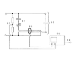
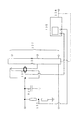
図2及び図3を参照して、本発明のインバータ駆動モータの絶縁評価方法及び装置の一実施例を説明する。図2は、本発明の一実施例の絶縁評価装置の構成を示している。本実施例の絶縁評価装置は、試験電源部1と、部分放電計測部2と、データ計測記録装置3で構成される。評価対象の試料絶縁材4は、モータ巻き線ターン間の絶縁部を模擬した要素モデルが用いられる。例えば、巻き線に用いる絶縁電線を撚り合わせた要素モデル、あるいは、平行巻電線試料などが使用される。
With reference to FIG.2 and FIG.3, one Example of the insulation evaluation method and apparatus of the inverter drive motor of this invention is described. FIG. 2 shows the configuration of an insulation evaluation apparatus according to an embodiment of the present invention. The insulation evaluation apparatus according to this embodiment includes a test
試験電源部1は、ピーク電圧Vm、パルス幅tw及び周波数fpの両極性交互パルス電圧を発生するように構成されている。試験電源部1は、ピーク値で0〜15kV以上のピーク電圧Vmを発生できることが望ましい。また、パルス幅twは5μs以下であり、特に0.1〜1.0μsの範囲では0.1μs以下の刻みでパルス幅twを常時もしくは電圧停止時に可変できることが望ましい。また、周波数fpは、インバータ電源のスイッチング周波数によって決まる。
The test
部分放電計測部2は、パルス電圧を試料絶縁材4に印加したときの部分放電発生頻度−電圧特性、及び継続して一定のパルス電圧を課電した際に試料が絶縁破壊に至るまでの部分放電信号強度と絶縁破壊に至るまでの絶縁寿命時間を計測するようになっている。
The partial
データ計測記録装置3は、コントロールライン5を介して試験電源部1のパルス電圧のピーク電圧Vm、パルス幅tw、周波数fpを制御すると同時に、試験電圧に同期して部分放電計測部2から部分放電計測データを取り込んで記録するようになっている。また、計測データは、部分放電発生頻度−電圧特性、絶縁破壊に至るまでの部分放電信号強度、絶縁破壊までの絶縁寿命時間−電圧特性のグラフにプロットするようになっている。
The data measurement /
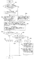
図3に、本実施例の絶縁評価装置で実施する絶縁評価方法のフローチャートを示す。 FIG. 3 shows a flowchart of an insulation evaluation method carried out by the insulation evaluation apparatus of this embodiment.
(ステップS1)
ここで、モータがインバータ駆動されるときのモータ端子における対地間サージ電圧の大きさΔVと、立ち上がり時間trと、周波数fpをシミュレーションもしくはモータを用いた計測によって求める。
(Step S1)
Here, the magnitude ΔV of the surge voltage to ground at the motor terminal when the motor is driven by the inverter, the rise time tr, and the frequency fp are obtained by simulation or measurement using the motor.
(ステップS2)
ステップS1の処理が不可能な場合は、ステップS2の処理により、異相間のサージ電圧の大きさΔVと、立ち上がり時間trと、周波数fpを求めて代用する。これは、インバータ電源とモータの接地インピーダンスが小さい場合には、対地間サージ電圧が相間サージ電圧とほぼ一致することを種々の検討によって得ており、そこで、ステップS1の処理が不可能な場合は、相間サージ電圧を対地間サージ電圧の代わりとして使用する。
(Step S2)
If the process in step S1 is impossible, the process calculates the surge voltage magnitude ΔV, rise time tr, and frequency fp between the different phases by the process in step S2. This indicates that when the ground impedance of the inverter power supply and the motor is small, the ground-to-ground surge voltage almost matches the phase-to-phase surge voltage by various studies. Therefore, when the process of step S1 is impossible The interphase surge voltage is used as an alternative to the ground surge voltage.
(ステップS3)
ここで、求めた対地間サージ電圧がモータ巻線に印加された際のモータ巻線ターン間に発生する分担電圧のピーク電圧Vmと、パルス幅twと、周波数fpをシミュレーションもしくはモータを用いた計測によって求める。
(Step S3)
Here, the peak voltage Vm of the shared voltage generated between the motor winding turns when the obtained ground surge voltage is applied to the motor winding, the pulse width tw, and the frequency fp are simulated or measured using a motor. Ask for.
また、得られたモータ巻線ターン間分担電圧のピーク電圧Vmと、対地間サージ電圧の大きさΔVとを用いて、後述の製品検査段階で用いる電圧分担率α(tr)を、次式(3)により求める。
α(tr)=Vm/ΔV (3)
ただし、α(tr):立ち上がり時間trのサージ電圧を印加したときのモータ巻線ターン間電圧分担率
Vm:モータ巻線ターン間分担電圧のピーク電圧
ΔV:対地間サージ電圧の大きさ
なお、巻線ターン間分担電圧のシミュレーションあるいは計測が困難な場合は、次のように簡易的に求めることができる。つまり、巻線ターン間分担電圧のピーク電圧Vmについては、次式(4)により求める。
Vm=ΔV・τ/tr (4)
ただし、τ:巻線ターン間分担電圧に伴う劣化を検討すべきモータ巻線部のサージ電圧伝播時間
また、パルス幅twについては、次式(5)により求める。
tr≦τの場合、 tw=τ
tr>τの場合、 tw=tr (5)
ただし、τ:巻線ターン間分担電圧に伴う劣化を対象とするモータ巻線部分のサージ電圧伝播時間
tr:サージ電圧立ち上がり時間
なお、図2(a)のパルス電圧のパルス幅twを5μs以下、特に0.1〜1.0μsの範囲では0.1μs以下の刻みで可変できるようにしている。その理由は、一般のモータのサージ電圧伝播時間τは、巻線ターン間の分担電圧に伴う劣化を検討すべきモータ巻線部では、種々の計測の結果、サージ電圧伝播時間τは多くとも5μsであり、一般には0.1〜1.0μsであったことによる。
Further, by using the obtained peak voltage Vm of the motor winding turn sharing voltage and the magnitude ΔV of the surge voltage to ground, a voltage sharing ratio α (tr) used in the product inspection stage described later is expressed by the following formula ( Obtained by 3).
α (tr) = Vm / ΔV (3)
Where α (tr) is the voltage sharing ratio between the turns of the motor winding when a surge voltage with a rise time tr is applied.
Vm: Peak voltage of the shared voltage between motor winding turns
ΔV: The magnitude of the surge voltage between the grounds If it is difficult to simulate or measure the voltage shared between winding turns, it can be easily obtained as follows. That is, the peak voltage Vm of the winding turn sharing voltage is obtained by the following equation (4).
Vm = ΔV · τ / tr (4)
However, τ: Surge voltage propagation time of the motor winding portion for which deterioration due to the winding turn sharing voltage should be examined. The pulse width tw is obtained by the following equation (5).
When tr ≦ τ, tw = τ
When tr> τ, tw = tr (5)
Where τ is the surge voltage propagation time of the motor winding part that is subject to deterioration due to the shared voltage between winding turns
tr: Surge voltage rise time The pulse width tw of the pulse voltage shown in FIG. 2A can be varied in steps of 5 μs or less, particularly 0.1 μs or less in the range of 0.1 to 1.0 μs. The reason for this is that the surge voltage propagation time τ of a general motor is 5 μs at most, as a result of various measurements, in the motor winding part that should be examined for deterioration due to the shared voltage between winding turns. Generally, it was from 0.1 to 1.0 μs.
(ステップS4)
ここにおいて、データ計測記録装置3は、試験電源部1を制御して、巻線ターン間分担電圧と同じピーク電圧Vm、パルス幅tw、繰り返し周波数fpの両極性交互パルス電圧を作成して試料絶縁材4に課電する。
(Step S4)
Here, the data measurement and
そして、データ計測記録装置3は、部分放電計測部2を制御して、両極性交互パルス電圧のピーク電圧Vmの1サージ電圧サイクルにおける部分放電発生頻度Npを計測して、図2(b)に示すピーク電圧Vm―部分放電発生頻度Npの特性データを取得する。また、図示していない一般的な正弦波電源装置で発生したピーク電圧Vmの正弦波電圧の1電圧サイクルにおける部分放電発生頻度Nsを計測して、ピーク電圧Vm−部分放電発生頻度Nsの特性データを取得する。
Then, the data measuring and
(ステップS5)
ステップS4の部分放電特性の計測後、試料絶縁材4には継続して同じピーク電圧Vmのパルス電圧及び正弦波電圧を印加し、試料絶縁材4の絶縁が破壊するまで部分放電信号強度Vpを計測するとともに、絶縁破壊に至るまでの絶縁寿命時間tp、tsを計測する。
(Step S5)
After measuring the partial discharge characteristics in step S4, the pulse voltage and sine wave voltage of the same peak voltage Vm are continuously applied to the
ステップS4、S5においては、ピーク電圧Vmを変化させて計測する。なお、正弦波電圧に対する部分放電特性及び絶縁寿命時間について、すでに過去に計測したデータがあればこれを使用することができる。 In steps S4 and S5, measurement is performed by changing the peak voltage Vm. In addition, about the partial discharge characteristic with respect to a sine wave voltage and the insulation lifetime, if there is already measured data in the past, this can be used.
また、ステップS5において、図2(c)に示すように、ピーク電圧Vmを一定としたときの、試料絶縁材4が初期から絶縁破壊に至るまでの部分放電信号強度Vpの経時変化を計測及び記録する。
Further, in step S5, as shown in FIG. 2C, the time-dependent change in the partial discharge signal intensity Vp from the initial stage to the dielectric breakdown of the
(ステップS6)
ステップS5における絶縁寿命時間tpの計測の場合、低電圧・長寿命領域ではパルス電圧による絶縁破壊までの時間が長くなるから、実用的でない。そこで、このような低電圧領域では、比較的短時間に計測できる正弦波電圧による絶縁寿命時間tsと、この電圧における部分放電発生頻度Nsと、パルス電圧課電時の部分放電発生頻度Npを用いて、次式(6)により、絶縁寿命時間tpを推定する。
tp=(Ns/Np)・ts (6)
(Step S6)
The measurement of the insulation life time tp in step S5 is not practical in the low voltage / long life region because the time until dielectric breakdown due to the pulse voltage becomes long. Therefore, in such a low voltage region, the insulation life time ts by a sine wave voltage that can be measured in a relatively short time, the partial discharge occurrence frequency Ns at this voltage, and the partial discharge occurrence frequency Np at the time of applying the pulse voltage are used. Thus, the insulation lifetime tp is estimated from the following equation (6).
tp = (Ns / Np) · ts (6)
同様の計算を繰り返すことで、パルス電圧下の絶縁寿命特性を、正弦波電圧下の絶縁寿命特性を(Ns/Np)だけシフトすることにより、図2(c)に示す絶縁寿命時間tp、tsとピーク電圧Vmとの関係を求めることができる。このようにして、試料絶縁材4について、ピーク電圧Vmに対する絶縁寿命時間tpの変化を表す絶縁寿命特性を得ることができる。
By repeating the same calculation, the insulation life characteristics under the pulse voltage are shifted from the insulation life characteristics under the sine wave voltage by (Ns / Np), so that the insulation life times tp and ts shown in FIG. And the peak voltage Vm can be obtained. In this way, with respect to the
(ステップS7〜S9)
ステップS6で得られたピーク電圧Vmの両極性交互パルス電圧に対する試料絶縁材4の絶縁寿命特性に基づいて、設計対象のインバータ駆動モータの絶縁設計を行うことができる。すなわち、ステップS7において、試料絶縁材4の絶縁寿命特性に基づいて、実際のモータ駆動時の巻線ターン間分担電圧のピーク電圧Vmにおける絶縁寿命時間tpを求める。次いで、ステップS8において、求めた絶縁寿命時間tpが、設計対象のモータの要求寿命に比べて長い場合には、ステップS9に進んで、モータの使用電圧や材料仕様などの設計データを決定し、製品の設計・生産工程に移行する。
(Steps S7 to S9)
Based on the insulation life characteristics of the
(ステップS10)
ステップS8の判断で、絶縁寿命時間tpが要求寿命に比して短い場合には、ステップS10に移行して、サージ電圧の大きさΔVを小さくするか、立ち上がり時間trを緩やかにして巻線ターン間分担電圧のピーク電圧Vmを低減する。あるいは、モータ巻線ターン間分担電圧が小さくなるように巻回数、巻線配列などのモータの巻線仕様を変更する。また、絶縁材料を放電劣化に強い材料に改良するか、絶縁厚みを厚くしたり、ワニス処理を施すなどして、絶縁寿命時間tpを長くする。放電劣化に強い材料に関しては、具体的には有機絶縁体中に占める無機フィラーの量を増加するなどの改良が考えられる。以上のような改良を施した後、再度、材料評価を実施、検討する。
(Step S10)
If it is determined in step S8 that the insulation life time tp is shorter than the required life, the process proceeds to step S10, where the surge voltage magnitude ΔV is reduced or the rise time tr is slowed down to turn the winding turn. The peak voltage Vm of the shared voltage is reduced. Alternatively, the winding specifications of the motor, such as the number of turns and the winding arrangement, are changed so that the divided voltage between the motor winding turns is reduced. In addition, the insulating life time tp is extended by improving the insulating material to a material resistant to discharge deterioration, increasing the insulating thickness, or performing varnish treatment. For materials that are resistant to discharge deterioration, specifically, improvements such as increasing the amount of inorganic filler in the organic insulator can be considered. After making the improvements as described above, material evaluation will be carried out and examined again.
(試験電源部1の実施例)
図4に、図2の試験電源部1の第一例を示す。本例の試験電源部1は、直流電源41の出力をパルススイッチ42で+側と−側を交互に切り替えて矩形波のパルス電圧を作成する。さらに、パルス電圧をハイパスフィルタ部43で所定のパルス幅の両極性交互パルス電圧になるように波形整形して、出力端子44から試料絶縁材4に出力する。パルススイッチ42には、正負2個のスイッチ素子を使用し、出力パルス電圧が正負対称になるようにしている。なお、直流電源41とパルススイッチ42は破線で示したコントロールライン45に接続されたデータ計測記録装置3よって制御される。図4では、直流電源41を1つの電源で構成し−側を接地しているが、直流電源41を+と−の2つの直流電源で構成し、これらの直列接続部の中間点を接地しても同様の波形を得ることができる。
(Example of test power supply unit 1)
FIG. 4 shows a first example of the test
図5に、試験電源部1の第二例を示す。本例の試験電源部1は、直流電源51の出力をパルススイッチ52にてON/OFFして矩形波のパルス電圧を作成し、さらにハイパスフィルタ部53で所定のパルス幅の両極性交互パルス電圧になるように波形整形し、出力端子54から試料絶縁材4に出力する。本例のパルススイッチ52は、スイッチ素子1個で構成される。しかし、本例では、パルススイッチの出力インピーダンス55を100Ω以下の低インピーダンスにしてあり、パルススイッチ52のスイッチ素子が切れる際に負極性の急峻な電圧変化が生じるため、ハイパスフィルタ処理後には正負対称の出力パルス電圧が得られる。なお、直流電源51とパルススイッチ52は破線で示したコントロールライン55に接続されたデータ計測記録装置3によって制御される。図5では直流電源51は1つの電源で構成し−側を接地しているが、直流電源51を+と−の2つの直流電源で構成し、これらの直列接続部の中間点を接地しても同様の波形を得ることができる。
FIG. 5 shows a second example of the test
(部分放電計測部2の実施例)
図6に、部分放電計測部2の回路構成の一例を示す。図6の部分放電計測回路は、電圧計測用分圧器61と、結合コンデンサ62、試料接続端子63、高周波電流プローブ64、部分放電電流波形計測用のデジタルオシロスコープ65で構成される。結合コンデンサ62の静電容量は、試料接続端子63に接続される試料絶縁材4の静電容量(図中、点線で示す。)に近づけるように調整される。高周波電流プローブ64には電線貫通式の電磁結合型の電流センサが用いられている。特に、結合コンデンサ62と試験電源部1の端子44との接続線、及び試料接続端子63と試験電源部1の端子44との接続線を、互いに逆方向に高周波電流プローブ64を貫通させている。これにより、パルス電圧に伴う充電電流をキャンセルし、試料絶縁材4で発生した部分放電電流のみを計測できるようにしている。パルス幅twの短いパルス電圧では、このように充電電流をキャンセルすることで高精度に部分放電を計測することができる。なお、高周波電流プローブには、クランプ式を用いることもできる。
(Example of partial discharge measuring unit 2)
FIG. 6 shows an example of a circuit configuration of the partial
部分放電を計測する高周波電流プローブ64の周波数帯域は1MHz〜1GHz、少なくとも10MHz〜100MHzである必要がある。なお、図では電流プローブに貫通させる結合コンデンサ62と試料接続端子63の接続線には低圧側の接続線を使用しているが、高圧側の接続線を使用してもよい。電流プローブ64と分圧器61で計測した部分放電電流強度Vp、発生頻度および印加電圧は、デジタルオシロスコープ65にて計測及び記録される。また、コントロールライン66に接続されたデータ計測記録装置3に記録される。ここで、デジタルオシロスコープ65の帯域は、DC〜1GHz以上、サンプリング速度は2GS/s以上あることが望ましく、少なくとも帯域はDC〜100MHz、サンプリング速度は200MS/sある必要がある。なお、デジタルオシロスコープ65は、同等の帯域、サンプリング速度、データ計測メモリ長を有するA/Dカードで代用することもできる。デジタルオシロスコープ65もしくはデジタルオシロスコープ65を制御するデータ計測記録装置3では、所定の波高値の電圧を試料に印加できなくなるか、放電にともなう電圧降下が0V近くに達するか、電流があらかじめ設定したリミット値を超えた場合に、試料絶縁材4の絶縁が破壊したと判断する。
The frequency band of the high-frequency current probe 64 for measuring the partial discharge needs to be 1 MHz to 1 GHz, at least 10 MHz to 100 MHz. In the drawing, a low-voltage side connection line is used as a connection line between the coupling capacitor 62 and the sample connection terminal 63 that penetrates the current probe, but a high-voltage side connection line may be used. The partial discharge current intensity Vp, occurrence frequency, and applied voltage measured by the current probe 64 and the voltage divider 61 are measured and recorded by the digital oscilloscope 65. Further, the data is recorded in the data
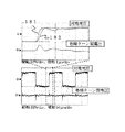
ここで、本発明のインバータ駆動モータの絶縁評価方法の技術的な意義について、図18に示す実測データに基づいて説明する。図18は、モータ端子と対地間にインバータサージ電圧を課電し、巻線ターン間分担電圧を計測した例を示す。同図(a)の横軸は1μs/divの時間を示し、縦軸は電圧を示す。同図(b)の横軸は50μs/divの時間を示し、縦軸は電圧を示す。 Here, the technical significance of the inverter drive motor insulation evaluation method of the present invention will be described based on the actual measurement data shown in FIG. FIG. 18 shows an example in which an inverter surge voltage is applied between the motor terminal and the ground, and a shared voltage between winding turns is measured. The horizontal axis of the figure (a) shows the time of 1 microsecond / div, and a vertical axis | shaft shows a voltage. The horizontal axis of the figure (b) shows time of 50 microseconds / div, and a vertical axis | shaft shows a voltage.
同図(b)に示す時間目盛が大きな場合の波形では、対地間サージ電圧の立ち上がり及び立下り部分において、巻線ターン間に正極性と負極性の両極性交互電圧が発生している。同図(b)の点線部を同図(a)の時間目盛が詳細な波形に拡大すると、モータ巻線の口出し側ターン181と内部側ターン182の間にサージ電圧の伝播時間遅れが認められ、この伝播時間遅れにともない巻線ターン間の分担電圧が発生している。巻線ターン間分担電圧のパルス幅は、約0.8μsであり、電圧持続時間がきわめて短いことが判る。 In the waveform when the time scale shown in FIG. 5B is large, positive and negative polarity alternating voltages are generated between the winding turns at the rising and falling portions of the surge voltage between the ground. When the dotted line in FIG. 5B is expanded to a detailed waveform in the time scale of FIG. 5A, a delay in the propagation time of the surge voltage is recognized between the lead-out turn 181 and the internal turn 182 of the motor winding. As a result of this propagation time delay, a shared voltage between winding turns is generated. It can be seen that the pulse width of the voltage between winding turns is about 0.8 μs, and the voltage duration is very short.
図19に、パルス電圧が空気に課電されたときの火花放電遅れのモデルを示す。一般に、空気に高電圧を印加した場合、空気は必ずしも直ちに火花放電(絶縁破壊)するわけではなく、一定の時間遅れを伴って火花放電に至る。この時間遅れを火花放電遅れ、あるいは火花遅れと呼び、この火花放電遅れは電極間に初期電子が偶然現れるまでの統計時間遅れと、電子が電界によって加速されながら、電子なだれを形成し、さらに電極からの二次電子放出や、ストリーマの形成によって火花放電が形成されるまでの形成時間遅れから構成される。ここで、火花放電遅れと電圧持続時間の関係を考察する。始めに、電圧印加時間が火花放電遅れに比し十分長い場合を考えると、例え電圧の立ち上がり時間が速くても、時間の経過とともに必ず放電に至る。一方、電圧の持続時間を短くし、電圧持続時間が火花放電遅れ未満になると、空気で火花放電が生じる前に電圧が低下してしまうため、火花放電が発生しない可能性(確率)が高くなる。同様のことが絶縁物中の空気にも発生し、パルス幅が狭い電圧では、絶縁物中の空気の放電(部分放電)が発生しない可能性(確率)が高くなり、絶縁物の劣化が抑制される可能性が高くなる。 FIG. 19 shows a model of a spark discharge delay when a pulse voltage is applied to air. In general, when a high voltage is applied to the air, the air does not necessarily immediately undergo a spark discharge (insulation breakdown), but reaches a spark discharge with a certain time delay. This time delay is called spark discharge delay or spark delay. This spark discharge delay is a statistical time delay until the initial electrons appear by chance between the electrodes, and an electron avalanche is formed while the electrons are accelerated by the electric field. Secondary electron emission from the light source and the formation time delay until a spark discharge is formed by the formation of a streamer. Here, the relationship between the spark discharge delay and the voltage duration is considered. First, considering the case where the voltage application time is sufficiently longer than the spark discharge delay, even if the rise time of the voltage is fast, discharge always occurs with the passage of time. On the other hand, if the voltage duration is shortened and the voltage duration is less than the spark discharge delay, the voltage drops before the spark discharge occurs in the air, so the possibility (probability) that spark discharge does not occur increases. . The same thing occurs in the air in the insulator, and at a voltage with a narrow pulse width, there is a high possibility (probability) that the discharge of the air in the insulator (partial discharge) does not occur and the deterioration of the insulator is suppressed. Is likely to be.
これらのことから、少なくとも絶縁材料の部分放電劣化特性を支配する電圧パラメータは、従来考えられてきた電圧立ち上がり時間ではなく、電圧持続時間、すなわちパルス電圧ではパルス幅であると考えられる。なお、この火花放電遅れは、これまでの検討の結果、数μs〜msオーダーに亘っていることを知見した。 From these facts, it is considered that the voltage parameter that governs at least the partial discharge deterioration characteristics of the insulating material is not the voltage rise time conventionally considered but the voltage duration, that is, the pulse width in the pulse voltage. In addition, as a result of the examination so far, it has been found that this spark discharge delay is on the order of several μs to ms.
一方、図18のモータ巻線ターン間に発生する分担電圧のパルス幅は1μs以下であり、火花放電遅れに比して十分短い。したがって、インバータ駆動時のモータ巻線ターン間では、従来の幅の広いパルス電圧や正弦波電圧に比し、部分放電が発生し絶縁劣化、破壊に至る可能性(確率)が低いと考えられる。なお、火花放電遅れは電圧が高くなると短くなることも、これまでの検討の結果、明らかになっている。本発明では、巻線ターン間の分担電圧を変化させて部分放電発生頻度を測定することで、このような火花放電遅れの電圧依存性も含めて評価している。 On the other hand, the pulse width of the shared voltage generated between the motor winding turns in FIG. 18 is 1 μs or less, which is sufficiently shorter than the spark discharge delay. Therefore, it is considered that the possibility (probability) that partial discharge occurs and causes insulation deterioration and breakdown is low between the motor winding turns when driving the inverter, as compared with the conventional wide pulse voltage and sine wave voltage. As a result of the examination so far, it has been clarified that the spark discharge delay becomes shorter as the voltage becomes higher. In the present invention, the partial discharge occurrence frequency is measured by changing the shared voltage between winding turns, and evaluation is made including the voltage dependency of such spark discharge delay.
以上の考察から、インバータ駆動モータでは、早期故障の原因となる巻線ターン間の絶縁材料を評価する場合には、少なくとも、モータ巻線ターン間の分担電圧のパルス幅を考慮した電圧で検討しなければならないことが判る。 Based on the above considerations, in inverter-driven motors, when evaluating the insulating material between winding turns that causes premature failure, consider at least a voltage that considers the pulse width of the shared voltage between the motor winding turns. I know I have to.
また、従来、パルス電圧の極性についても、単極性、両極性のデータが混在し議論されてきたが、少なくともモータ巻線ターン間の絶縁材料を評価する場合には、両極性の交互パルス電圧を課電して評価しなければならないことが判る。 Conventionally, the polarity of the pulse voltage has been discussed with a mixture of unipolar and bipolar data. However, at least when evaluating the insulating material between the motor winding turns, the alternating pulse voltage of both polarities is used. I understand that I have to evaluate it by applying electricity.
さらに、従来のモータ巻線試験には、一般に市販されている立ち上がり時間のみが高速で立下りでは指数関数的に電圧低下する雷インパルス電圧、もしくは波尾に振動波形が重畳したインパルス電圧が使用されてきた。しかしながら、図18を見ると、インバータパルス電圧では電圧の立ち上がり時間だけでなく、立ち下がり時間も高速であり、立ち上がりと立下り部分の両方に巻線ターン間分担電圧が発生している。したがって、モータ巻線ターン間にインバータ駆動時と同じ電圧を発生させ、モータ製品の検査や診断をする場合には、従来の立ち上がり時間のみが高速な電源で試験するのではなく、立ち上がり時間と立ち下がり時間がともに高速なパルス電圧を使用しなければならないことが判る。 Furthermore, the conventional motor winding test uses a lightning impulse voltage that drops only exponentially when the rise time is fast and falls, or an impulse voltage with a vibration waveform superimposed on the wave tail. I came. However, as shown in FIG. 18, not only the voltage rise time but also the fall time is fast in the inverter pulse voltage, and the winding turn-sharing voltage is generated at both the rise and fall portions. Therefore, when the same voltage as that when driving the inverter is generated between the motor winding turns and the motor product is inspected or diagnosed, only the conventional rise time is not tested with a high-speed power supply. It can be seen that a fast pulse voltage must be used for both fall times.
以上説明したように、本発明のインバータ駆動モータの絶縁評価方法及び装置は、インバータ駆動モータの絶縁で最も厳しいのは、インバータパルス電圧がサージ電圧として作用する同一巻線の巻線ターン間であることに鑑み、しかも、立ち上がりが急峻なサージ電圧の伝播過程で各巻線ターン間に加わるサージ電圧の分担率が異なってくることに鑑みなされたものである。 As described above, in the inverter drive motor insulation evaluation method and apparatus of the present invention, the most severe insulation of the inverter drive motor is between winding turns of the same winding in which the inverter pulse voltage acts as a surge voltage. In view of this, in addition, the sharing ratio of the surge voltage applied between the winding turns in the process of propagation of the surge voltage with a steep rise is different.
そこで、本実施例は、巻線ターン間に発生するモータ巻線ターン間分担電圧のピーク電圧Vmとパルス幅twと周波数fpを有する両極性交互パルス電圧を試験電圧として試料絶縁材の寿命時間tpを計測し、ピーク電圧Vmに対する寿命時間tpの変化をその試料絶縁材の絶縁寿命特性として取得することにより、インバータパルス電圧に対する絶縁材の性能を評価することができ、信頼性の高い絶縁評価方法を確立することができる。 Therefore, in the present embodiment, the life time tp of the sample insulating material is obtained by using the peak voltage Vm of the divided voltage between the motor winding turns generated between the winding turns, the bipolar alternating pulse voltage having the pulse width tw and the frequency fp as the test voltage. Is measured, and the change in the life time tp with respect to the peak voltage Vm is acquired as the insulation life characteristic of the sample insulation material, so that the performance of the insulation material with respect to the inverter pulse voltage can be evaluated, and a highly reliable insulation evaluation method Can be established.
図7及び図8を参照して、本発明のインバータ駆動モータの絶縁検査方法及び装置の一実施例を説明する。図7は、本実施例の絶縁検査方法が適用された製品絶縁寿命検査装置を示す。製品絶縁寿命検査装置は、試験電源部71と、部分放電計測部72と、これらの試験電源部71と部分放電計測部72を制御する機能を兼ね備えたデータ計測記録装置73で構成される。検査対象の試料モータ75には、個々の製品を使用する。試験電源部71は、インバータ駆動時のモータ端子におけるサージ電圧の大きさΔV、立ち上がり時間trを模擬したサージ電圧を発生する。サージ電圧の大きさΔVには0〜15kV以上の電圧を発生できることが望ましい。また、立ち上がり時間trは1μs以下であり、特に0.1〜1.0μsの範囲内で0.1μs以下の刻みで常時もしくは電圧停止時に可変できることが望ましい。あるいは、立ち上がり時間trを固定した装置では、試験中のモータ巻線ターン間分担電圧が、インバータ駆動時の巻線ターン間分担電圧と同じになるように、次式(7)に示す換算式にて換算したサージ電圧にて試験する。
ΔV(試験装置)=
ΔV(Inv)・α(tr(Inv))/α(tr(試験装置)) (7)
ただし、ΔV(試験装置):試験装置のサージ電圧の大きさ
ΔV(Inv):インバータ駆動モータのモータ端のサージ電圧の大きさ
α(tr(試験装置)):
試験装置のサージ電圧を印加したときのモータ巻線ターン間電圧分担率
α(tr(Inv)):
インバータ駆動モータのモータ端サージ電圧を印加したときのモータ巻線 ターン間電圧分担率
tr(試験装置):試験装置のサージ電圧立ち上がり時間
tr(Inv):
インバータ駆動モータのモータ端のサージ電圧立ち上がり時間
With reference to FIG. 7 and FIG. 8, an embodiment of an insulation inspection method and apparatus for an inverter drive motor according to the present invention will be described. FIG. 7 shows a product insulation life test apparatus to which the insulation test method of this embodiment is applied. The product insulation life test apparatus includes a test power supply unit 71, a partial discharge measurement unit 72, and a data measurement recording device 73 having a function of controlling the test power supply unit 71 and the partial discharge measurement unit 72. Individual products are used for the
ΔV (test equipment) =
ΔV (Inv) · α (tr (Inv)) / α (tr (test apparatus)) (7)
However, ΔV (test equipment): magnitude of surge voltage of test equipment ΔV (Inv): magnitude of surge voltage at the motor end of the inverter drive motor α (tr (test equipment)):
Voltage sharing ratio between motor windings when a surge voltage of the test apparatus is applied α (tr (Inv)):
Motor winding when the motor-side surge voltage of the inverter drive motor is applied Turn-to-turn voltage sharing ratio tr (test device): surge voltage rise time tr (Inv) of the test device:
Surge voltage rise time at the motor end of the inverter drive motor
なお、サージ電圧の立ち下がり時間には、立ち上がり時間と同じ時間を採用することが望ましい。また、サージ電圧のパルス幅pwには、製品に回転子を組み込み回転試験ができる状態では、1μs〜10msの範囲を採用できる。しかし、回転子を組み込んでいない状態では、逆起電力が発生せず、モータ巻線に過大な電流が流れるため、パルス幅pwには1μs〜10μsの範囲を採用することが望ましい。サージ電圧の波形の一例を、図7(a)に示す。 It is desirable to use the same time as the rise time for the fall time of the surge voltage. Further, the range of 1 μs to 10 ms can be adopted as the pulse width pw of the surge voltage in a state where a rotor is incorporated in the product and a rotation test can be performed. However, in the state where the rotor is not incorporated, no counter electromotive force is generated, and an excessive current flows in the motor winding. Therefore, it is desirable to adopt a range of 1 μs to 10 μs for the pulse width pw. An example of the surge voltage waveform is shown in FIG.
部分放電計測部72は、サージ電圧を試料モータ75に印加したときの部分放電発生頻度−モータ課電電圧特性を計測する。データ計測記録装置73は、試験電源部71のサージ電圧の大きさΔV、立ち上がり時間tr、パルス幅pw、繰り返し周波数fpを制御し、試験電源電圧に同期して部分放電計測データを部分放電計測部72からコントロールライン74を介して取り込み、データを記録する。得られたデータは、図7(b)に示す部分放電発生頻度Np、Nx−課電電圧特性のグラフにプロットされる。
The partial discharge measuring unit 72 measures partial discharge occurrence frequency-motor applied voltage characteristics when a surge voltage is applied to the
図8に、本実施例の製品絶縁検査装置で実施する絶縁検査方法のフローチャートを示す。 FIG. 8 shows a flowchart of an insulation inspection method carried out by the product insulation inspection apparatus of this embodiment.
(ステップS21)
まず、試料モータ75がインバータ駆動されるときのモータ端子の対地間サージ電圧の大きさΔV、立ち上がり時間tr、繰り返し周波数fpをシミュレーションもしくはモータを用いた計測によって求める。
(Step S21)
First, the magnitude ΔV of the surge voltage to ground at the motor terminal when the
(ステップS22)
ステップS21の処理が不可能な場合は、ステップS22において、インバータ電源とモータの接地インピーダンスが小さい場合には、対地間サージ電圧が相間サージ電圧とほぼ一致することが種々の検討によって得られていることから、相間サージ電圧を対地間サージ電圧の代わりとして使用する。
(Step S22)
When the process of step S21 is impossible, it has been obtained through various studies that the ground-to-ground surge voltage substantially coincides with the inter-phase surge voltage when the ground impedance of the inverter power supply and the motor is small in step S22. Therefore, the surge voltage between phases is used instead of the surge voltage between ground.
(ステップS23)
ステップS21又はS22で求めたサージ電圧の大きさΔV、立ち上がり時間tr、繰り返し周波数fpのサージ電圧を模擬した電圧、あるいは実際のインバータ電圧を個々の製品である試料モータ75に課電し、1サージ電圧サイクルあたりの部分放電発生頻度Nxを求める。
(Step S23)
Surge voltage magnitude ΔV obtained in step S21 or S22, rise time tr, voltage imitating surge voltage of repetition frequency fp, or actual inverter voltage is applied to sample
(ステップS24)
ステップ23の処理と並行して、図2の絶縁材評価で得られたモータ巻線ターン間のピーク電圧Vmと部分放電発生頻度Npのグラフ、及びピーク電圧Vmと絶縁寿命時間Npにおけるピーク電圧Vmを、次式(8)によってサージ電圧の大きさΔVに変換し、これを標準品の絶縁寿命特性とする。
ΔV=Vm/α(tr) (8)
ただし、ΔV:サージ電圧の大きさ
α(tr):立ち上がり時間trのサージ電圧を印加したときのモータ巻線 ターン間電圧分担率
Vm:モータ巻線ターン間分担電圧のピーク電圧
(Step S24)
In parallel with the processing of step 23, a graph of the peak voltage Vm between the motor winding turns and the partial discharge occurrence frequency Np obtained in the insulating material evaluation of FIG. 2, and the peak voltage Vm at the peak voltage Vm and the insulation lifetime Np. Is converted into a surge voltage magnitude ΔV by the following equation (8), which is used as the insulation life characteristic of the standard product.
ΔV = Vm / α (tr) (8)
Where ΔV is the magnitude of the surge voltage α (tr) is the voltage sharing ratio between the motor windings when the surge voltage of the rise time tr is applied Vm is the peak voltage of the sharing voltage between the motor windings
(ステップS25)
個々の製品の絶縁が破壊されるまでの絶縁寿命時間txは、個々の製品に大きさΔVのサージ電圧を課電したときの部分放電発生頻度Nxと、標準品に大きさΔVのサージ電圧を課電したときの絶縁破壊までの時間tpと部分放電発生頻度Npを用いて、次式(9)により求める。
tx=(Np/Nx)・tp (9)
異なるサージ電圧の大きさΔVに対する部分放電発生頻度Nxを用いて、同様にして標準品の絶縁寿命特性を(Np/Nx)だけシフトすることで、個々の製品の絶縁寿命特性が作成できる。
(Step S25)
The insulation life time tx until the insulation of each product is broken down is the frequency Nx of partial discharge when a surge voltage of magnitude ΔV is applied to each product and the surge voltage of magnitude ΔV on the standard product. Using the time tp until breakdown and the partial discharge occurrence frequency Np when applied, the following equation (9) is used.
tx = (Np / Nx) · tp (9)
By using the partial discharge occurrence frequency Nx for different surge voltage magnitudes ΔV and similarly shifting the insulation life characteristics of standard products by (Np / Nx), the insulation life characteristics of individual products can be created.
(ステップS26〜S32)
ステップS25で得られた絶縁寿命特性において、絶縁寿命時間txが製品の要求寿命以上であれば、ステップS27に進んで合格とし出荷する。
(Steps S26 to S32)
In the insulation life characteristic obtained in step S25, if the insulation life time tx is equal to or longer than the required life of the product, the process proceeds to step S27 and is shipped.
一方、不良品となった場合には、ステップS28に進んで、インバータ駆動モータのモータ端子のサージ電圧の大きさΔVを小さくするか、電圧立ち上がり時間trを長くできるかどうかを検討する。この検討の結果が可能であれば、ステップS29に進んで、仕様を限定した上で合格として出荷する。 On the other hand, if it becomes a defective product, the process proceeds to step S28 to examine whether the magnitude ΔV of the surge voltage at the motor terminal of the inverter drive motor can be reduced or whether the voltage rise time tr can be increased. If the result of this examination is possible, the process proceeds to step S29, the specification is limited, and the product is shipped as acceptable.
ステップS28で、さらに不合格になった製品については、ステップS30からステップS31に進み、絶縁破壊するまでサージ電圧を計測して課電し、絶縁破壊に至るまでの絶縁寿命時間、及び絶縁破壊に至るまでの部分放電信号強度を計測する。得られた絶縁寿命時間と、先の検査で予測した不良品の絶縁寿命特性を比較し、実測データと予測データの補正係数を導出して、予測方法を補正することにより、寿命予測精度を向上させる。 For products that are further rejected in step S28, the process proceeds from step S30 to step S31, where the surge voltage is measured and applied until breakdown, and the insulation life time until the breakdown occurs, and the breakdown Measure the partial discharge signal intensity. Improve life prediction accuracy by comparing the obtained insulation life time with the insulation life characteristics of defective products predicted in the previous inspection, deriving the correction coefficient of measured data and prediction data, and correcting the prediction method Let
また、不良品の絶縁破壊までの部分放電信号強度の経時変化は、絶縁寿命時間txで規格化した上で、同じく絶縁寿命時間tpで規格化した標準品の部分放電信号強度の経時変化と比較する。そして、それらに差があれば、補正計数を求めて標準品の部分放電信号強度の経時変化データを補正するとともに、部分放電信号強度の経時変化のばらつきを把握する。ステップS31で絶縁破壊させた不良品については絶縁破壊箇所を探索し、絶縁材料もしくは生産方法のどこに原因があったか特定し、絶縁材料及び製品生産工程にフィードバックする。 In addition, the temporal change in the partial discharge signal strength until the dielectric breakdown of the defective product is normalized with the insulation life time tx and compared with the change over time in the partial discharge signal strength of the standard product similarly normalized with the insulation life time tp. To do. If there is a difference between them, a correction count is obtained to correct the temporal change data of the partial discharge signal intensity of the standard product, and grasp the variation of the partial discharge signal intensity over time. For the defective product that has undergone dielectric breakdown in step S31, the location of the dielectric breakdown is searched, the cause of the insulating material or the production method is identified, and the result is fed back to the insulating material and product production process.
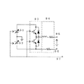
(試験電源部71の実施例)
図9に、製品絶縁寿命検査装置の試験電源部71の第一例を示す。試験電源部71は、直流電源91、92の出力をパルススイッチ93で交互に切り替え、立ち上がり時間と立ち下がり時間が同じ正負対称な矩形波のパルス電圧を作成し、さらにこれを立ち上がり/立ち下がり時間調整部94でサージ電圧の立ち上がり/立ち下がり時間が所定の値になるように調整し、一方の出力端子95に出力する。すなわち、図9の回路では実際の2レベルインバータに近い正負対称なサージ電圧を出力することができる。他方の低圧側電圧の出力端子96は、試料モータ75の他相の巻線に接続され、他相の巻線の電位が変動しないようにすると同時に、モータ内に電荷を充/放電する働きをする。但し、パルススイッチ93の電流容量が大きく、パルススイッチ93を通してモータ内に蓄積した電荷を充/放電できるか、あるいはモータ巻線の静電容量が小さい場合には端子96を設けたり、他相に接続する必要はない。直流電源91、92とパルススイッチ93は破線で示したコントロールライン97に接続されたデータ計測記録装置73によって制御される。
(Example of test power supply unit 71)
FIG. 9 shows a first example of the test power supply unit 71 of the product insulation life test apparatus. The test power supply unit 71 alternately switches the outputs of the DC power supplies 91 and 92 with the
図10に、製品絶縁寿命検査装置の試験電源部71の第二例を示す。試験電源部71は、直流電源101、102の出力をパルススイッチ103でON/OFFして正負対称な矩形波のパルス電圧を作成し、さらにこれを立ち上がり/立ち下がり時間調整部104でサージ電圧の立ち上がり/立ち下がり時間が所定の値になるように調整、出力端子105に出力し、実際の2レベルインバータに近い正負対称なサージ電圧を出力することができる。本例のパルススイッチ103のスイッチ素子は1個のみである。しかし、本例では、パルススイッチ103の出力インピーダンス108が100Ω以下の低インピーダンスにしてあり、パルススイッチ103が切れる際、矩形波に負極性の急峻な電圧変化が生じるため立ち上がりと立ち下がりの両方が急峻な矩形波電圧が得られる。他方の低圧側電圧の出力端子106は、モータの他相の巻線に接続され、他相の巻線の電位が変動しないようにすると同時に、モータ内に電荷を充/放電する働きをする。但し、第一例と同じく、パルススイッチ103の電流容量が大きいか、モータ巻線の静電容量が小さい場合には端子106を設けたり、他相に接続する必要はない。直流電源101、102とパルススイッチ103は破線で示したコントロールライン107に接続されたデータ計測記録装置73によって制御される。
In FIG. 10, the 2nd example of the test power supply part 71 of a product insulation lifetime inspection apparatus is shown. The test power supply unit 71 turns on and off the outputs of the DC power supplies 101 and 102 with a pulse switch 103 to create a positive / negative symmetrical rectangular wave pulse voltage, and further generates a surge voltage with a rise / fall
図11に、製品絶縁寿命検査装置の試験電源部71の第三例を示す。試験電源部71は、直流電源111の出力をパルススイッチ113で交互に切り替えて立ち上がり時間と立ち下がり時間が同じ矩形波のパルス電圧を作成し、さらにこれを立ち上がり/立ち下がり時間調整部114でサージ電圧の立ち上がり/立ち下がり時間が所定の値になるように調整し、出力端子115に出力する。他方の低圧側電圧の出力端子116は、モータの他相の巻線に接続され、他相の巻線の電位が変動しないようにすると同時に、モータ内に電荷を充/放電する働きをする。直流電源111とパルススイッチ113は破線で示したコントロールライン117に接続されたデータ計測記録装置73によって制御される。なお、本例では、直流電源が1つになった点を除けば、図9の第一例と同じ回路構成である。しかし、本例では、直流電源の一端が接地されているため、パルススイッチ113の少なくとも一方については、コントロールラインの信号をパルススイッチに適した信号に変換するドライバをアースに対して高電圧に浮かせる必要はなくなり、パルススイッチの内部絶縁構成が図9のパルススイッチに比し簡単になる。 In FIG. 11, the 3rd example of the test power supply part 71 of a product insulation lifetime inspection apparatus is shown. The test power supply unit 71 alternately switches the output of the DC power supply 111 with the pulse switch 113 to create a rectangular wave pulse voltage with the same rise time and fall time, and further generates a surge voltage with the rise / fall time adjustment unit 114. The rise / fall time of the voltage is adjusted to a predetermined value and output to the output terminal 115. The other low-voltage side voltage output terminal 116 is connected to the other-phase winding of the motor to prevent the potential of the other-phase winding from fluctuating and at the same time to charge / discharge electric charges in the motor. The DC power supply 111 and the pulse switch 113 are controlled by a data measurement recording device 73 connected to a control line 117 indicated by a broken line. In this example, the circuit configuration is the same as that of the first example in FIG. 9 except that the number of DC power supplies is one. However, in this example, since one end of the DC power supply is grounded, at least one of the pulse switches 113 causes a driver that converts a signal on the control line to a signal suitable for the pulse switch is floated to a high voltage with respect to the ground. There is no need, and the internal insulation structure of the pulse switch is simplified compared to the pulse switch of FIG.
図12に、製品絶縁寿命検査装置の試験電源部71の第四例を示す。試験電源部71は、直流電源121の出力をパルススイッチ123でON/OFFして矩形波のパルス電圧を作成し、さらにこれを立ち上がり/立ち下がり時間調整部124でサージ電圧の立ち上がり/立ち下がり時間が所定の値になるように調整し、出力端子125に出力する。本例のパルススイッチ103のスイッチ素子は1個のみである。しかし、本例ではパルススイッチ123の出力インピーダンス128が100Ω以下の低インピーダンスにしてあり、パルススイッチ123が切れる際、矩形波に負極性の急峻な電圧変化が生じるため、立ち上がりと立ち下がりの両方が急峻な矩形波電圧が得られる。他方の低圧側電圧の出力端子126は、モータの他相の巻線に接続され、他相の巻線の電位が変動しないようにすると同時に、モータ内に電荷を充/放電する働きをする。直流電源121とパルススイッチ123は破線で示したコントロールライン127に接続されたデータ計測記録装置よって制御される。
FIG. 12 shows a fourth example of the test power source 71 of the product insulation life test apparatus. The test power supply unit 71 turns the output of the DC power supply 121 on / off with the pulse switch 123 to create a rectangular pulse voltage, and further rises / falls the surge voltage with the rise / fall time adjustment unit 124. Is adjusted to a predetermined value and output to the
(部分放電計測回路72の実施例)
図13に、製品絶縁寿命検査装置の部分放電計測回路72の一例を示す。部分放電計測回路72は、電圧計測用分圧器131と、結合コンデンサ132と、高周波電流プローブ134と、部分放電電流波形計測用のデジタルオシロスコープ135と、三相巻線を有する試料の被試験相を切り替えるUVW切り替えスイッチユニット136で構成される。
(Example of partial discharge measuring circuit 72)
FIG. 13 shows an example of the partial discharge measuring circuit 72 of the product insulation life test apparatus. The partial discharge measuring circuit 72 includes a voltage measuring voltage divider 131, a coupling capacitor 132, a high-frequency current probe 134, a
結合コンデンサ132の静電容量は、試料モータ75の対地間静電容量と同程度が望ましく、具体的には10pF〜1000pFの間に設定される。高周波電流プローブ134には、結合コンデンサ132の2本の出力線を逆方向に貫通させ、試料の二相に課電したパルス電圧に伴う充電電流をキャンセルし、試料内部で発生した部分放電電流のみを計測できるようにしている。高周波電流プローブ134の周波数帯域は1MHz〜1GHz、少なくとも10MHz〜100MHzあることが望ましい。UVW切り替えスイッチユニット136の入力には、電流プローブに逆方向に貫通させた2本の高圧線と、試験電源71から供給される低圧線が入力される。
The capacitance of the coupling capacitor 132 is preferably about the same as the capacitance between the
一方、出力端子137は、試料のU、V、Wの3相巻線の各入力に接続され、試験時にはUVW切り替えスイッチユニット136は、コントロールライン138の制御信号によって、(U、V−W)、(V,W−U)、(W,U−V)のように、三相巻線を有する試料の二相を高圧、残りの一相を低圧にするように試験相を切り替える。 On the other hand, the output terminal 137 is connected to each input of the U, V, and W three-phase windings of the sample, and the UVW changeover switch unit 136 is controlled by the control signal of the control line 138 (U, VW) during the test. , (V, W-U), and (W, U-V), the test phase is switched so that the two phases of the sample having the three-phase winding are set to high pressure and the remaining one phase is set to low pressure.
電流プローブ134と分圧器131で計測した部分放電電流強度、発生頻度及び印加電圧は、デジタルオシロスコープ135にて計測、記録されるとともに、コントロールライン138に接続されたデータ計測記録装置73によって記録される。デジタルオシロスコープ135の帯域はDC〜1GHz以上、サンプリング速度は2GS/s以上あることが望ましく、少なくともDC〜100MHz、サンプリング速度は200MS/sである必要がある。なお、デジタルオシロスコープ135は、同等の帯域、サンプリング速度、メモリ長を有するA/Dカードで代用することもできる。デジタルオシロスコープ135もしくはデジタルオシロスコープ135を制御するデータ計測記録装置73では、所定の波高値の電圧が試料に印加されなくなるか、放電にともなう電圧降下が0V近くに達し、かつ、部分放電電流があらかじめ設定したリミット値を超えた場合に試料モータの絶縁が破壊したと判断する。
The partial discharge current intensity, occurrence frequency, and applied voltage measured by the current probe 134 and the voltage divider 131 are measured and recorded by the
図14に、UVW自動切換えスイッチユニット136の回路構成例を示す。入力端子141には、高周波電流プローブに逆方向に貫通させた2本の高圧線と、低圧線の計3本の入力線が接続される。これらの端子は、スイッチユニット142の3つの各スイッチに供給される。スイッチユニット142の3つのスイッチの切り替え端子は、試料モータのU、V、W相にそれぞれ接続される。スイッチユニット142は、コントロールライン148の制御信号によって、U、V、W相を、高周波電流プローブに逆方向に貫通させた2本の高圧線と、低圧線の3ラインのいずれかに接続される。
FIG. 14 shows a circuit configuration example of the UVW automatic changeover switch unit 136. The
以上では、回転子を組み込んでいない状態で製品モータを試験する装置構成を示した。しかし、回転子を組み込み製品モータの回転試験をできる状態では、実際のインバータ電源を試験電源に採用することができる。図7の製品絶縁寿命検査装置の試験電源及び部分放電計測部76に、実際のインバータ電源を組み込んだ例を図15に示す。インバータ電源151の出力には、電圧計測用分圧器152と部分放電計測用の高周波電流プローブ153が接続された後、U、V、W出力端子154に接続される。電流プローブ153と分圧器152で計測した部分放電電流強度、発生頻度及び印加電圧は、Compact PCIユニット155に組み込まれたA/D変換ボード156にて計測、記録される。計測データはI/O信号変換部157に接続されたコントロールライン158を介してデータ計測記録装置73に記録される。インバータ電源151及びCompact PCIユニットはコントロールライン158を介して送られてくる「試験開始」、「データ送受信」、「試験終了」などのコマンドによって制御される。
The apparatus configuration for testing the product motor in a state where the rotor is not incorporated has been shown above. However, an actual inverter power supply can be used as a test power supply in a state where a rotor is incorporated and a rotation test of a product motor can be performed. FIG. 15 shows an example in which an actual inverter power source is incorporated in the test power source and partial discharge measuring unit 76 of the product insulation life test apparatus of FIG. A voltage measuring voltage divider 152 and a partial discharge measuring high-frequency current probe 153 are connected to the output of the inverter power supply 151, and then connected to the U, V, and
試験中にインバータ電源151が所定の電圧を出力できなくなるか、過電流エラーを発生するか、分圧器152で計測した電圧波形において、所定の波高値の電圧が試料に印加できないか、放電にともなう電圧降下が0V近くに達するか、あるいは電流プローブ153にて、予め設定したリミット値を超える電流が検出された場合に、インバータ電源151、Compact PCIユニット155、もしくはこれらを制御するデータ計測記録装置73は、試料モータの絶縁が破壊したと判断する。
During the test, the inverter power supply 151 cannot output a predetermined voltage, an overcurrent error occurs, a voltage waveform measured by the voltage divider 152 cannot be applied to the sample, or a discharge occurs. When the voltage drop reaches close to 0 V or when the current probe 153 detects a current exceeding a preset limit value, the inverter power supply 151, the
図16及び図17を参照して、本発明のインバータ駆動モータの診断方法及び装置の一実施例を説明する。図16は、本実施例の診断方法が適用された診断装置を示す。本実施例の診断装置は、試験電源部161と、部分放電計測部162と、これらの試験電源部161と部分放電計測部162の制御機能を兼ね備えたデータ計測記録装置164で構成される。
With reference to FIGS. 16 and 17, an embodiment of an inverter drive motor diagnosis method and apparatus according to the present invention will be described. FIG. 16 shows a diagnostic apparatus to which the diagnostic method of this embodiment is applied. The diagnostic apparatus of the present embodiment includes a test power supply unit 161, a partial discharge measurement unit 162, and a data
診断対象の試料モータ163は、フィールドで絶縁劣化した製品モータとする。試験電源部161と部分放電計測部162で構成される試験電源・部分放電計測部165には、インバータ電源を使用した図15の構成を採用することができ、実際のインバータ電圧波形下における部分放電信号をオンラインで常時計測することができる。また、試験電源・部分放電計測部165には、製品絶縁寿命検査装置の図9〜14の試験電源部71、部分放電計測部72を使用することもできる。この場合、絶縁診断の際に、フィールドに試験装置を運搬し、試料モータ163に接続して診断するオフライン定期診断となる。いずれの場合についても、試験電源・部分放電計測部165の部分放電計測部162では部分放電信号強度の経時変化を計測する。データ計測記録装置164は、試験電源部161の電圧を制御するとともに、試験電源電圧に同期して部分放電信号強度の計測データを部分放電計測部162からコントロールライン166を介して取り込み記録する。得られた計測データは、部分放電信号強度−課電時間特性のグラフにプロットされる。
The sample motor 163 to be diagnosed is a product motor whose insulation has deteriorated in the field. The test power source / partial discharge measuring unit 165 composed of the test power source unit 161 and the partial discharge measuring unit 162 can adopt the configuration of FIG. 15 using an inverter power source, and the partial discharge under the actual inverter voltage waveform. The signal can be constantly measured online. Moreover, the test power source / partial discharge measuring unit 165 may be the test power source unit 71 and the partial discharge measuring unit 72 shown in FIGS. In this case, when performing an insulation diagnosis, an off-line periodic diagnosis is performed in which the test apparatus is transported to the field and connected to the sample motor 163 for diagnosis. In any case, the partial discharge measuring unit 162 of the test power source / partial discharge measuring unit 165 measures a change in the partial discharge signal intensity with time. The data measurement /
図17に、本実施例の診断装置の診断フローを示す。
(ステップS41)
ステップS41においては、絶縁破壊又は故障前に製品を交換する閾値年数xを決める。例えば、自動車用モータの場合、車検期間が2年であるため、xには2年を選択することができる。
FIG. 17 shows a diagnosis flow of the diagnosis apparatus of this embodiment.
(Step S41)
In step S41, a threshold number of years x for replacing the product before dielectric breakdown or failure is determined. For example, in the case of a motor for automobiles, since the vehicle inspection period is 2 years, 2 years can be selected for x.
(ステップS42、S43)
ここで、標準品の部分放電信号強度の経時変化データにおいて、絶縁寿命tpのx年前の部分放電信号強度を求めて、これを製品交換の部分放電信号強度の閾値θthとする。フィールド製品の部分放電は、図16の装置によって常時もしくは定期的に計測し、これを部分放電信号強度の閾値θthと比較し、部分放電信号強度が閾値を超えた場合には、ステップS43に進んで、製品を新品に交換するとともに、劣化品を回収する。
(Steps S42 and S43)
Here, in the time-dependent change data of the partial discharge signal strength of the standard product, the partial discharge signal strength x years before the insulation life tp is obtained, and this is set as the threshold value θth of the partial discharge signal strength for product replacement. The partial discharge of the field product is always or periodically measured by the apparatus shown in FIG. 16, and is compared with the threshold value θth of the partial discharge signal intensity. If the partial discharge signal intensity exceeds the threshold value, the process proceeds to step S43. Then, replace the product with a new one and collect the deteriorated product.
(ステップS44)
回収した劣化品は、絶縁が破壊するまで継続してインバータサージ電圧を課電する。このとき、部分放電信号強度及び残存の絶縁寿命時間を計測し、絶縁寿命時間txで規格化した部分放電信号強度の経時変化において、信号強度のばらつきを把握するとともに、製品交換の部分放電信号強度の閾値を補正する。
(Step S44)
The recovered deteriorated product continues to apply an inverter surge voltage until the insulation breaks down. At this time, the partial discharge signal strength and the remaining insulation life time are measured, and the variation in signal strength is grasped in the temporal change of the partial discharge signal strength normalized by the insulation life time tx. The threshold value is corrected.
(ステップS45)
絶縁破壊させた劣化品について、絶縁破壊した劣化弱点箇所を探索し、劣化原因を特定する。
(Step S45)
For deteriorated products that have undergone dielectric breakdown, search for degradation weak points where dielectric breakdown has occurred, and identify the cause of deterioration.
(ステップS46)
ステップS45で得られたデータを基に、次期製品では絶縁劣化箇所に電圧が加わらないようにモータ設計、絶縁構造設計を変更する。あるいは、絶縁劣化しやすい弱点箇所の絶縁を強化する。あるいは、絶縁劣化しやすい弱点箇所の製品製造時の検査を強化する。
(Step S46)
On the basis of the data obtained in step S45, the motor design and the insulation structure design are changed so that no voltage is applied to the insulation deterioration portion in the next product. Or the insulation of the weak point location which is easy to deteriorate is strengthened. Alternatively, the inspection at the time of product manufacture of weak points where insulation is likely to deteriorate will be strengthened.
1 試験電源部
2 部分放電計測部
3 データ計測記録装置
4 試料絶縁材
5 コントロールライン
DESCRIPTION OF
Claims (1)
Priority Applications (1)
| Application Number | Priority Date | Filing Date | Title |
|---|---|---|---|
| JP2011042274A JP5113919B2 (en) | 2011-02-28 | 2011-02-28 | Inspection drive diagnosis method for inverter drive motor |
Applications Claiming Priority (1)
| Application Number | Priority Date | Filing Date | Title |
|---|---|---|---|
| JP2011042274A JP5113919B2 (en) | 2011-02-28 | 2011-02-28 | Inspection drive diagnosis method for inverter drive motor |
Related Parent Applications (1)
| Application Number | Title | Priority Date | Filing Date |
|---|---|---|---|
| JP2006053341A Division JP4726654B2 (en) | 2006-02-28 | 2006-02-28 | Insulation drive motor insulation evaluation method, design method using the method, inspection method, diagnosis method, and apparatus thereof |
Publications (2)
| Publication Number | Publication Date |
|---|---|
| JP2011158479A JP2011158479A (en) | 2011-08-18 |
| JP5113919B2 true JP5113919B2 (en) | 2013-01-09 |
Family
ID=44590526
Family Applications (1)
| Application Number | Title | Priority Date | Filing Date |
|---|---|---|---|
| JP2011042274A Expired - Fee Related JP5113919B2 (en) | 2011-02-28 | 2011-02-28 | Inspection drive diagnosis method for inverter drive motor |
Country Status (1)
| Country | Link |
|---|---|
| JP (1) | JP5113919B2 (en) |
Families Citing this family (3)
| Publication number | Priority date | Publication date | Assignee | Title |
|---|---|---|---|---|
| JP5882019B2 (en) * | 2011-10-17 | 2016-03-09 | 株式会社日立製作所 | Inverter-driven rotating electrical machine testing method and rotating electrical machine testing method |
| JP6140229B2 (en) * | 2015-08-28 | 2017-05-31 | ファナック株式会社 | Machine learning device and method for learning predicted life of electric motor, life prediction device and motor system provided with machine learning device |
| JP6245484B1 (en) * | 2016-07-07 | 2017-12-13 | 株式会社安川電機 | Motor control system, initial charging device, and failure detection method |
Family Cites Families (3)
| Publication number | Priority date | Publication date | Assignee | Title |
|---|---|---|---|---|
| JP2000002744A (en) * | 1998-06-12 | 2000-01-07 | Toyo Electric Mfg Co Ltd | Method for diagnosing coil insulation of rotating machine and device therefor |
| JP4378478B2 (en) * | 2004-07-22 | 2009-12-09 | 国立大学法人九州工業大学 | Method and apparatus for measuring partial discharge start voltage |
| JP4418320B2 (en) * | 2004-07-28 | 2010-02-17 | 株式会社日立産機システム | Measuring method of partial discharge between motor winding turns |
-
2011
- 2011-02-28 JP JP2011042274A patent/JP5113919B2/en not_active Expired - Fee Related
Also Published As
| Publication number | Publication date |
|---|---|
| JP2011158479A (en) | 2011-08-18 |
Similar Documents
| Publication | Publication Date | Title |
|---|---|---|
| JP4726654B2 (en) | Insulation drive motor insulation evaluation method, design method using the method, inspection method, diagnosis method, and apparatus thereof | |
| Meyer et al. | Influence of impulse voltage repetition frequency on RPDIV in partial vacuum | |
| JP6835554B2 (en) | Systems and methods for monitoring electrical machinery | |
| EP2402775B1 (en) | Insulation inspection/diagnosis device and method of dynamo-electric machine | |
| CN104797949A (en) | Insulation inspection device for motors and insulation inspection method for motors | |
| Kimura et al. | PDIV characteristics of twisted-pair of magnet wires with repetitive impulse voltage | |
| JP5113919B2 (en) | Inspection drive diagnosis method for inverter drive motor | |
| Romano et al. | A new technique for partial discharges measurement under DC periodic stress | |
| US20140062525A1 (en) | Inverter-driven rotary electric machine, insulation inspection method and insulation inspection apparatus | |
| JP5134602B2 (en) | Insulation drive motor insulation design method and manufacturing method | |
| JP4378478B2 (en) | Method and apparatus for measuring partial discharge start voltage | |
| Lewin et al. | Locating partial discharge sources in high voltage transformer windings | |
| CN106771902B (en) | method for determining GIS corona discharge degree | |
| CN102288881A (en) | Method for diagnosing severity of discharging shortcoming of oil paper insulation thorn of transformer | |
| Wang et al. | Effect of repetitive square voltage frequency on partial discharge features | |
| JP2015072183A (en) | Insulation diagnosis method between winding layers of winding device | |
| JP2012112925A (en) | Insulation defect inspection device of rotating electrical machine coil, and method for inspecting insulation defect | |
| Naderiallaf et al. | Investigating the effect of space charge accumulation on partial discharge activity for new and thermally aged glass fibre insulated wire | |
| Corr et al. | Partial discharge testing of defects in dielectric insulation under DC and voltage ripple conditions | |
| Wolbank | On line detection of inverter fed AC machine insulation health state using high frequency voltage excitation | |
| Naderiallaf et al. | Glass fibre insulated wire assessment under partial discharges activity via dielectric dissipation factor measurements | |
| Cheng et al. | Analysis of the influence of outside equipments on the online deformation detection of transformers | |
| Zoeller et al. | Insulation condition monitoring of traction drives based on transient current signal resulting from differential and common mode excitation | |
| CN113358990B (en) | Oscillatory wave test system | |
| Wu et al. | Study on PD detection method in GIS under oscillating impulse voltage based on UHF method |
Legal Events
| Date | Code | Title | Description |
|---|---|---|---|
| A621 | Written request for application examination |
Free format text: JAPANESE INTERMEDIATE CODE: A621 Effective date: 20110228 |
|
| A131 | Notification of reasons for refusal |
Free format text: JAPANESE INTERMEDIATE CODE: A131 Effective date: 20120703 |
|
| TRDD | Decision of grant or rejection written | ||
| A01 | Written decision to grant a patent or to grant a registration (utility model) |
Free format text: JAPANESE INTERMEDIATE CODE: A01 Effective date: 20120925 |
|
| A01 | Written decision to grant a patent or to grant a registration (utility model) |
Free format text: JAPANESE INTERMEDIATE CODE: A01 |
|
| A61 | First payment of annual fees (during grant procedure) |
Free format text: JAPANESE INTERMEDIATE CODE: A61 Effective date: 20121012 |
|
| FPAY | Renewal fee payment (event date is renewal date of database) |
Free format text: PAYMENT UNTIL: 20151019 Year of fee payment: 3 |
|
| R150 | Certificate of patent or registration of utility model |
Ref document number: 5113919 Country of ref document: JP Free format text: JAPANESE INTERMEDIATE CODE: R150 Free format text: JAPANESE INTERMEDIATE CODE: R150 |
|
| S533 | Written request for registration of change of name |
Free format text: JAPANESE INTERMEDIATE CODE: R313533 |
|
| R350 | Written notification of registration of transfer |
Free format text: JAPANESE INTERMEDIATE CODE: R350 |
|
| LAPS | Cancellation because of no payment of annual fees |