JP5113532B2 - Needleless transdermal delivery device - Google Patents
Needleless transdermal delivery device Download PDFInfo
- Publication number
- JP5113532B2 JP5113532B2 JP2007555318A JP2007555318A JP5113532B2 JP 5113532 B2 JP5113532 B2 JP 5113532B2 JP 2007555318 A JP2007555318 A JP 2007555318A JP 2007555318 A JP2007555318 A JP 2007555318A JP 5113532 B2 JP5113532 B2 JP 5113532B2
- Authority
- JP
- Japan
- Prior art keywords
- electromagnetic actuator
- electrical input
- force
- reservoir
- coil
- Prior art date
- Legal status (The legal status is an assumption and is not a legal conclusion. Google has not performed a legal analysis and makes no representation as to the accuracy of the status listed.)
- Active
Links
Images


Classifications
-
- A—HUMAN NECESSITIES
- A61—MEDICAL OR VETERINARY SCIENCE; HYGIENE
- A61M—DEVICES FOR INTRODUCING MEDIA INTO, OR ONTO, THE BODY; DEVICES FOR TRANSDUCING BODY MEDIA OR FOR TAKING MEDIA FROM THE BODY; DEVICES FOR PRODUCING OR ENDING SLEEP OR STUPOR
- A61M5/00—Devices for bringing media into the body in a subcutaneous, intra-vascular or intramuscular way; Accessories therefor, e.g. filling or cleaning devices, arm-rests
- A61M5/178—Syringes
- A61M5/30—Syringes for injection by jet action, without needle, e.g. for use with replaceable ampoules or carpules
-
- A—HUMAN NECESSITIES
- A61—MEDICAL OR VETERINARY SCIENCE; HYGIENE
- A61D—VETERINARY INSTRUMENTS, IMPLEMENTS, TOOLS, OR METHODS
- A61D7/00—Devices or methods for introducing solid, liquid, or gaseous remedies or other materials into or onto the bodies of animals
-
- A—HUMAN NECESSITIES
- A61—MEDICAL OR VETERINARY SCIENCE; HYGIENE
- A61M—DEVICES FOR INTRODUCING MEDIA INTO, OR ONTO, THE BODY; DEVICES FOR TRANSDUCING BODY MEDIA OR FOR TAKING MEDIA FROM THE BODY; DEVICES FOR PRODUCING OR ENDING SLEEP OR STUPOR
- A61M5/00—Devices for bringing media into the body in a subcutaneous, intra-vascular or intramuscular way; Accessories therefor, e.g. filling or cleaning devices, arm-rests
- A61M5/178—Syringes
- A61M5/20—Automatic syringes, e.g. with automatically actuated piston rod, with automatic needle injection, filling automatically
-
- A—HUMAN NECESSITIES
- A61—MEDICAL OR VETERINARY SCIENCE; HYGIENE
- A61M—DEVICES FOR INTRODUCING MEDIA INTO, OR ONTO, THE BODY; DEVICES FOR TRANSDUCING BODY MEDIA OR FOR TAKING MEDIA FROM THE BODY; DEVICES FOR PRODUCING OR ENDING SLEEP OR STUPOR
- A61M2205/00—General characteristics of the apparatus
- A61M2205/35—Communication
- A61M2205/3546—Range
- A61M2205/3561—Range local, e.g. within room or hospital
-
- A—HUMAN NECESSITIES
- A61—MEDICAL OR VETERINARY SCIENCE; HYGIENE
- A61M—DEVICES FOR INTRODUCING MEDIA INTO, OR ONTO, THE BODY; DEVICES FOR TRANSDUCING BODY MEDIA OR FOR TAKING MEDIA FROM THE BODY; DEVICES FOR PRODUCING OR ENDING SLEEP OR STUPOR
- A61M5/00—Devices for bringing media into the body in a subcutaneous, intra-vascular or intramuscular way; Accessories therefor, e.g. filling or cleaning devices, arm-rests
- A61M5/178—Syringes
- A61M5/20—Automatic syringes, e.g. with automatically actuated piston rod, with automatic needle injection, filling automatically
- A61M5/204—Automatic syringes, e.g. with automatically actuated piston rod, with automatic needle injection, filling automatically connected to external reservoirs for multiple refilling
-
- A—HUMAN NECESSITIES
- A61—MEDICAL OR VETERINARY SCIENCE; HYGIENE
- A61M—DEVICES FOR INTRODUCING MEDIA INTO, OR ONTO, THE BODY; DEVICES FOR TRANSDUCING BODY MEDIA OR FOR TAKING MEDIA FROM THE BODY; DEVICES FOR PRODUCING OR ENDING SLEEP OR STUPOR
- A61M5/00—Devices for bringing media into the body in a subcutaneous, intra-vascular or intramuscular way; Accessories therefor, e.g. filling or cleaning devices, arm-rests
- A61M5/178—Syringes
- A61M5/31—Details
- A61M5/315—Pistons; Piston-rods; Guiding, blocking or restricting the movement of the rod or piston; Appliances on the rod for facilitating dosing ; Dosing mechanisms
- A61M5/31525—Dosing
-
- A—HUMAN NECESSITIES
- A61—MEDICAL OR VETERINARY SCIENCE; HYGIENE
- A61M—DEVICES FOR INTRODUCING MEDIA INTO, OR ONTO, THE BODY; DEVICES FOR TRANSDUCING BODY MEDIA OR FOR TAKING MEDIA FROM THE BODY; DEVICES FOR PRODUCING OR ENDING SLEEP OR STUPOR
- A61M5/00—Devices for bringing media into the body in a subcutaneous, intra-vascular or intramuscular way; Accessories therefor, e.g. filling or cleaning devices, arm-rests
- A61M5/178—Syringes
- A61M5/31—Details
- A61M5/315—Pistons; Piston-rods; Guiding, blocking or restricting the movement of the rod or piston; Appliances on the rod for facilitating dosing ; Dosing mechanisms
- A61M5/31533—Dosing mechanisms, i.e. setting a dose
- A61M5/31545—Setting modes for dosing
- A61M5/31546—Electrically operated dose setting, e.g. input via touch screen or plus/minus buttons
-
- A—HUMAN NECESSITIES
- A61—MEDICAL OR VETERINARY SCIENCE; HYGIENE
- A61M—DEVICES FOR INTRODUCING MEDIA INTO, OR ONTO, THE BODY; DEVICES FOR TRANSDUCING BODY MEDIA OR FOR TAKING MEDIA FROM THE BODY; DEVICES FOR PRODUCING OR ENDING SLEEP OR STUPOR
- A61M5/00—Devices for bringing media into the body in a subcutaneous, intra-vascular or intramuscular way; Accessories therefor, e.g. filling or cleaning devices, arm-rests
- A61M5/178—Syringes
- A61M5/31—Details
- A61M5/32—Needles; Details of needles pertaining to their connection with syringe or hub; Accessories for bringing the needle into, or holding the needle on, the body; Devices for protection of needles
- A61M5/329—Needles; Details of needles pertaining to their connection with syringe or hub; Accessories for bringing the needle into, or holding the needle on, the body; Devices for protection of needles characterised by features of the needle shaft
- A61M5/3291—Shafts with additional lateral openings
-
- A—HUMAN NECESSITIES
- A61—MEDICAL OR VETERINARY SCIENCE; HYGIENE
- A61M—DEVICES FOR INTRODUCING MEDIA INTO, OR ONTO, THE BODY; DEVICES FOR TRANSDUCING BODY MEDIA OR FOR TAKING MEDIA FROM THE BODY; DEVICES FOR PRODUCING OR ENDING SLEEP OR STUPOR
- A61M5/00—Devices for bringing media into the body in a subcutaneous, intra-vascular or intramuscular way; Accessories therefor, e.g. filling or cleaning devices, arm-rests
- A61M5/48—Devices for bringing media into the body in a subcutaneous, intra-vascular or intramuscular way; Accessories therefor, e.g. filling or cleaning devices, arm-rests having means for varying, regulating, indicating or limiting injection pressure
- A61M5/482—Varying injection pressure, e.g. by varying speed of injection
-
- A—HUMAN NECESSITIES
- A61—MEDICAL OR VETERINARY SCIENCE; HYGIENE
- A61M—DEVICES FOR INTRODUCING MEDIA INTO, OR ONTO, THE BODY; DEVICES FOR TRANSDUCING BODY MEDIA OR FOR TAKING MEDIA FROM THE BODY; DEVICES FOR PRODUCING OR ENDING SLEEP OR STUPOR
- A61M5/00—Devices for bringing media into the body in a subcutaneous, intra-vascular or intramuscular way; Accessories therefor, e.g. filling or cleaning devices, arm-rests
- A61M5/48—Devices for bringing media into the body in a subcutaneous, intra-vascular or intramuscular way; Accessories therefor, e.g. filling or cleaning devices, arm-rests having means for varying, regulating, indicating or limiting injection pressure
- A61M5/484—Regulating injection pressure
Description
本出願は、2006年2月10日付の発明の名称「Controlled Needle-Free Transport(制御式無針経皮輸送装置)」の出願(代理人事件番号第0050.2079-001号)(2005年2月11日付の米国特許仮出願第60/652,483号の利益を主張している)の継続出願である。上記出願の全内容は、参照により本明細書に引用したものとする。 This application is an application of the title of the invention “Controlled Needle-Free Transport” dated February 10, 2006 (agent case number 0050.2079-001) (February 11, 2005). (Which claims the benefit of US Provisional Application No. 60 / 652,483, dated). The entire contents of the above application are incorporated herein by reference.
人の患者または農業動物への薬物などの液体の注射は、様々な方法で実施されている。薬剤を送入する最も容易な方法の1つは、体の最も外側の保護層である皮膚を通しての方法である。皮膚は、角質層、顆粒層、有棘層、および基底層を含む表皮と、特に乳頭層を含む真皮とで構成されている。角質層は、死んだ細胞組織で形成された丈夫なうろこ状の組織である。角質層は、皮膚の表面から約10〜20ミクロンにわたって広がり、血液は供給されていない。この細胞の層の密度ゆえ、皮膚を貫いて体内または体外へと化合物を移動させることは、きわめて困難である。 Injection of liquids, such as drugs, into human patients or agricultural animals is performed in a variety of ways. One of the easiest ways to deliver drugs is through the skin, the outermost protective layer of the body. The skin is composed of the epidermis including the stratum corneum, the granular layer, the spinous layer, and the basal layer, and in particular the dermis including the papillary layer. The stratum corneum is a strong scaly tissue formed of dead cell tissue. The stratum corneum extends from about 10-20 microns from the surface of the skin and no blood is supplied. Due to the density of this layer of cells, it is very difficult to move the compound through the skin into and out of the body.
皮膚を通して局所的に薬物を送達する現行の技法として、針または他の皮膚貫通装置を使用する方法が挙げられる。針またはランセットを用いるような侵襲的な方法は、角質層の障壁機能を効果的に破壊する。しかし、これらの方法は、局所的な皮膚の損傷、出血、および注射部位における感染の危険、ならびに廃棄しなければならない汚染された針またはランセットの発生などといったいくつかの大きな欠点を有している。さらに、これらの装置が農業動物に薬物を注入するのに使用される場合、ときには針が破損して動物の体内に埋もれたままになることがある。したがって、動物において針が折れる恐れなく、少量の薬剤を皮膚を通して正確かつ迅速に注入できれば好都合であると考えられる。 Current techniques for delivering drugs locally through the skin include the use of needles or other skin penetration devices. Invasive methods such as using a needle or lancet effectively destroy the barrier function of the stratum corneum. However, these methods have several major drawbacks such as local skin damage, bleeding, and risk of infection at the injection site, as well as the occurrence of contaminated needles or lancets that must be discarded . Furthermore, when these devices are used to inject drugs into agricultural animals, sometimes the needles break and remain buried in the animal's body. Therefore, it would be advantageous to be able to accurately and quickly inject a small amount of drug through the skin without fear of the needle breaking in the animal.
薬物を生体に効果的に送達するために、無針式装置を使用することが提案されてきた。例えば、それら提案の装置のいくつかにおいては、薬物をチャンバから体内に吐出するために加圧ガスが使用されている。他の装置においては、蓄勢されたばねが解放され、チャンバに力を加えて、薬物を吐出させる。しかし、これらの種類の装置においては、ガスの膨張またはばねの伸張に伴い薬物に加えられる圧力が低下する。しかし、注入圧力は、注入期間のあいだ実質的に同じ値を維持することが望ましく、あるいは上昇が望まれることもある。無針式注入装置の例は、米国特許第6,939,323号の発明の名称「Needleless Injector(無針式注入器)」、および2003年9月8日付の米国特許出願第10/657,734号の発明の名称「Needleless Drug Injection Device(無針式薬物注入装置)」に記載されており、これらの両方の全内容は、参照により本明細書に引用したものとする。 It has been proposed to use a needleless device to effectively deliver drugs to the body. For example, in some of these proposed devices, pressurized gas is used to expel the drug from the chamber into the body. In other devices, the stored springs are released and force is applied to the chamber to expel the drug. However, in these types of devices, the pressure applied to the drug decreases as the gas expands or the spring extends. However, it may be desirable to maintain the injection pressure at substantially the same value during the injection period, or it may be desired to increase. Examples of needleless injection devices include the title “Needleless Injector” of US Pat. No. 6,939,323 and the name of the invention of US patent application Ser. No. 10 / 657,734, Sep. 8, 2003. “Needleless Drug Injection Device”, the entire contents of both of which are hereby incorporated by reference.
別の無針式注入装置は、きわめて限られた意味で制御可能であり(例えば、ガス放出式アクチュエータまたはばね式アクチュエータ)、あるいはフィード−フォワードという意味でのみ制御可能であり(例えば、ニチノールとして知られているニッケル‐チタニウム合金などの形状記憶材料)、注入プロファイルが前もって決定され、注入に先立って圧力アクチュエータに前もって送られる。 Other needleless infusion devices can be controlled in a very limited sense (eg, outgassing or spring actuators) or only in a feed-forward sense (eg, known as Nitinol). Shape memory materials such as nickel-titanium alloys), the injection profile is determined in advance and sent to the pressure actuator prior to injection.
本発明の態様によれば、サーボ制御式の無針輸送装置が、生体の表面を貫いて物質を輸送する。この装置は、制御可能性および高度な予測可能性の両者を備える高速かつ高圧のパルスを生成できるアクチュエータを備えている。装置は、1つ以上のセンサから入力を受け取るサーボコントローラと組み合わせることができる。有利には、輸送装置は、輸送の圧力プロファイルをリアルタイムで調節または調整することができる。すなわち、輸送装置は、輸送の間に検出される物理的特性に応じて、輸送の間における輸送圧力のプロファイルを調節することができる。 According to an aspect of the present invention, a servo-controlled needleless transport device transports a substance through the surface of a living body. The device includes an actuator capable of generating high speed and high pressure pulses with both controllability and high predictability. The device can be combined with a servo controller that receives input from one or more sensors. Advantageously, the transport device can adjust or adjust the transport pressure profile in real time. That is, the transport device can adjust the profile of transport pressure during transport depending on the physical characteristics detected during transport.
サーボ制御式無針注入器により、特定の動物および/または他の局所の環境要素の要件に応じてリアルタイムで動的に制御または調整される、動物体内への処方物の注入が実現される。このような制御により、皮膚の局所的な厚さおよび/または温度などの環境要素に応じて注入圧力を調節することで、単一の注入装置であっても、他の条件および要件に応じて制御された処方物の注入を実現できる。 Servo-controlled needleless injectors enable the injection of a formulation into the animal that is dynamically controlled or adjusted in real time depending on the requirements of the particular animal and / or other local environmental factors. Such control allows the injection pressure to be adjusted according to environmental factors such as local thickness and / or temperature of the skin, so that even a single injection device can be subject to other conditions and requirements. Controlled formulation injection can be achieved.
本発明の一態様においては、無針式経皮輸送装置が、物質を貯蔵するリザーバ、リザーバに連通しているノズル、およびリザーバに連結している制御可能な電磁アクチュエータを備えている。電磁アクチュエータは、磁界を供給する固定磁石アセンブリ、および磁石アセンブリに対してスライド可能に配置されたコイルアセンブリを備えている。コイルアセンブリは、電気入力を受け取り、これに応答して受け取った入力に比例した力を生成する。力は、電気入力によってコイルアセンブリに発生する電流と磁界との相互作用からもたらされる。この力を、リザーバと生体との間の無針での物質の輸送に利用することができる。このように、ローレンツ力による駆動によって、流体などの物質が体の表面を貫いて輸送される。この無針での輸送は、動作中であっても、受け取る入力の変化に応じて変化してもよい。 In one aspect of the present invention, a needleless transdermal delivery device includes a reservoir for storing a substance, a nozzle in communication with the reservoir, and a controllable electromagnetic actuator coupled to the reservoir. The electromagnetic actuator includes a fixed magnet assembly that supplies a magnetic field, and a coil assembly that is slidably disposed with respect to the magnet assembly. The coil assembly receives an electrical input and in response generates a force proportional to the received input. The force comes from the interaction between the current and the magnetic field generated in the coil assembly by the electrical input. This force can be used to transport a substance without a needle between the reservoir and the living body. In this way, a substance such as a fluid is transported through the surface of the body by driving by the Lorentz force. This needleless transport may change in response to changes in input received, even during operation.
本明細書に記載の無針式薬物注入装置および方法は、特別に構成された電磁アクチュエータを1つ以上のノズルと組み合わせて使用することにより、最初にランセットまたは針で皮膚を貫通することなく選択された深さまで動物の皮膚を通して薬物を効果的に注入できる。同じ装置を使用して、動物からサンプルを採取することができる。 The needleless drug infusion device and method described herein can be selected without first penetrating the skin with a lancet or needle by using a specially configured electromagnetic actuator in combination with one or more nozzles. The drug can be effectively injected through the skin of the animal to the desired depth. Samples can be taken from animals using the same device.
制御可能な電磁アクチュエータは、双方向性であり、第1の電気入力に応答して正の力を生成でき、第2の電気入力に応答して負の力を生成できる。電磁アクチュエータが、ノズルを通して物質を押し出し、生体の表面を貫通するのに充分な速度を有するジェット噴流を生成する。例えば、いくつかの実施形態においては、物質が少なくとも毎秒約100メートルの注入速度でノズルを通って吐出される。さらに、力およびノズルを制御して、所望の深さへの注入を生成できる。電気入力信号は、充電式電源によって提供できる。いくつかの実施形態においては、制御可能な電磁アクチュエータそのものが、充電式電源を充電するように構成されている。 The controllable electromagnetic actuator is bidirectional and can generate a positive force in response to the first electrical input and can generate a negative force in response to the second electrical input. An electromagnetic actuator pushes material through the nozzle and produces a jet jet having a sufficient speed to penetrate the surface of the living body. For example, in some embodiments, the substance is ejected through the nozzle at an injection rate of at least about 100 meters per second. In addition, forces and nozzles can be controlled to produce injections to a desired depth. The electrical input signal can be provided by a rechargeable power source. In some embodiments, the controllable electromagnetic actuator itself is configured to charge a rechargeable power source.
装置はさらに、制御可能な電磁アクチュエータに電気的に結合したコントローラを備えていてもよい。装置はさらに、コントローラに電気的に結合した少なくとも1つのセンサを備えることができる。センサは物理的特性を検出し、コントローラが検出された物理的特性に応じて電気入力を生成または供給する。例えば、検出される特性は、位置、力、圧力、電流、および電圧のうちの1つ以上であってよい。コントローラは、電気入力の生成に寄与するプロセッサを備えることができる。装置は、随意により、体から採取したサンプルを分析するように構成された分析器を備えている。コントローラは、サンプルの分析に応じた電気入力を供給するように構成することができる。 The apparatus may further comprise a controller electrically coupled to the controllable electromagnetic actuator. The apparatus can further comprise at least one sensor electrically coupled to the controller. The sensor detects a physical property and the controller generates or provides an electrical input depending on the detected physical property. For example, the detected property may be one or more of position, force, pressure, current, and voltage. The controller can comprise a processor that contributes to the generation of the electrical input. The apparatus optionally includes an analyzer configured to analyze a sample taken from the body. The controller can be configured to provide an electrical input in response to the analysis of the sample.
いくつかの実施形態においては、さらにリモート通信インタフェースが、コントローラに電気的に結合されて設けられている。この構成では、コントローラが、リモート通信インタフェースを介して受信した通信に応答して電気入力を生成することができる。 In some embodiments, a remote communication interface is further provided that is electrically coupled to the controller. In this configuration, the controller can generate an electrical input in response to communications received via the remote communication interface.
装置は、複数の独立した無針式輸送を提供できる多数回放出(マルチショット)装置として構成できる。有利には、それらの無針式輸送を、高速で連続的に生じさせることができる。この構成は、多数の輸送物を投与することにより、表面全体にわたり間隔を空けている、大きな表面積の処置を可能にする。 The device can be configured as a multi-shot device that can provide multiple independent needle-free transports. Advantageously, their needleless transport can occur continuously at high speed. This configuration allows for the treatment of large surface areas that are spaced across the surface by administering multiple transports.
電磁アクチュエータは、磁界を発生する磁石アセンブリを備えることができる。磁石アセンブリは一般に、ノズルを基準にして所定の位置に固定される。アクチュエータは、電気入力に関連する電流を流す少なくとも1回巻きの導電コイルアセンブリをさらに備えている。コイルアセンブリは、磁石アセンブリに対してスライド可能に配置されている。コイルアセンブリに生じた電流が、磁界と相互作用して、電流および磁界の方向および大きさに応じた力を生成する。好ましくは、磁界は、コイルに対して半径方向に向けられている。 The electromagnetic actuator can comprise a magnet assembly that generates a magnetic field. The magnet assembly is generally fixed in place with respect to the nozzle. The actuator further comprises at least one turn of a conductive coil assembly that carries a current associated with the electrical input. The coil assembly is slidably disposed with respect to the magnet assembly. The current generated in the coil assembly interacts with the magnetic field to generate a force that depends on the direction and magnitude of the current and the magnetic field. Preferably, the magnetic field is directed radially with respect to the coil.
機械的な力が、一端がノズルに結合されているリザーバに加えられ、リザーバ内に圧力を発生させる。圧力の大きさは、機械的な力に応じて変化し、生体とリザーバとの間に生体の表面を貫く物質の輸送を生じる。有利には、加えられる力は双方向であって、同じアクチュエータにより正の圧力および負の圧力(すなわち、真空)を生み出す。さらに、加えられる機械的な力は、電気入力を変化させることによって、動作サイクル中に変化させることができる。 A mechanical force is applied to the reservoir, one end of which is coupled to the nozzle, creating a pressure in the reservoir. The magnitude of the pressure changes depending on the mechanical force, resulting in the transport of a substance through the surface of the living body between the living body and the reservoir. Advantageously, the applied force is bi-directional and produces a positive pressure and a negative pressure (ie a vacuum) by the same actuator. Furthermore, the applied mechanical force can be changed during the operating cycle by changing the electrical input.
いくつかの実施形態においては、生成される力の発生に関連する立ち上がり時間が、約5ミリ秒以下である。アクチュエータによって生じる力およびストロークは、少なくとも約300マイクロリットルにのぼる量の物質を輸送するのに充分な大きさおよび継続時間である。アクチュエータの小型化および小電力により、リザーバ、ノズル、電源、および制御可能な電気アクチュエータを備える可搬の手持ちユニットが可能となる。 In some embodiments, the rise time associated with the generation of the generated force is about 5 milliseconds or less. The force and stroke produced by the actuator is large enough and duration to transport an amount of material up to at least about 300 microliters. The miniaturization and low power of the actuator allows for a portable handheld unit with a reservoir, nozzle, power supply, and controllable electric actuator.
この装置を使用して病気を治療する方法は、最初に無針式経皮輸送装置によって生体の表面を貫通することを含んでいる。次に、この無針式装置によってリザーバ内に真空を生成することにより、体内からサンプルまたはボーラスをリザーバへ吸引し、生体からサンプルが採取される。次に、有効成分(活性化合物)の投与量が、採取したサンプルに応じて決定される。無針式装置が、決定された量の活性化合物を生体に注入する。例えば、患者から血液サンプルを抽出することができる。このサンプルが分析され、血糖値が決定される。次いで、決定された値を用いて、患者についてインスリンの投与量を計算する。この投与量が、装置への電気入力を制御することによって投与される。 A method of treating a disease using this device involves first penetrating the surface of the living body with a needleless transdermal delivery device. Next, by generating a vacuum in the reservoir by the needleless device, the sample or bolus is sucked from the body into the reservoir, and the sample is collected from the living body. Next, the dose of the active ingredient (active compound) is determined according to the collected sample. A needleless device injects a determined amount of the active compound into the body. For example, a blood sample can be extracted from a patient. This sample is analyzed to determine the blood glucose level. The determined value is then used to calculate the insulin dose for the patient. This dose is administered by controlling the electrical input to the device.
サンプルの採取は、生理食塩水などの第1物質の注入を含むことができる。次いで、同じ無針式装置を使用して、サンプルが採取され、再び注入される。サンプルの再注入を複数回繰り返し、体から適正な量の間質液などで構成されたボーラスを得ることができる。 Collecting the sample can include injecting a first substance, such as saline. The sample is then taken and injected again using the same needleless device. By re-injecting the sample a plurality of times, a bolus composed of an appropriate amount of interstitial fluid can be obtained from the body.
本発明の別の態様においては、線形電磁アクチュエータが、磁界を発生する固定磁石アセンブリ、および電気入力を受け取るコイルを備えている。コイルは、磁石アセンブリに対してスライド可能に配置されている。さらに装置は、コイルの少なくとも一部分とスライド可能に係合するベアリングを備えている。コイル内の電気入力と磁界との相互作用によって生成される力に応じたコイルの直線運動が、ベアリングによって容易になる。 In another aspect of the invention, a linear electromagnetic actuator comprises a fixed magnet assembly that generates a magnetic field and a coil that receives an electrical input. The coil is slidably disposed with respect to the magnet assembly. The apparatus further includes a bearing that slidably engages at least a portion of the coil. The bearing facilitates linear motion of the coil in response to the force generated by the interaction between the electrical input in the coil and the magnetic field.
本明細書においては、本発明を、無針式装置での輸送に関連して説明するが、本明細書に記載される概念の1つ以上を針と組み合わることにより、体表面を貫く物質の輸送を達成してもよい。このとき、体表面は最初に針によって貫通されてもよい。 In the present specification, the present invention will be described in connection with transport in a needleless device, but a substance that penetrates the body surface by combining one or more of the concepts described herein with a needle. May be achieved. At this time, the body surface may first be penetrated by the needle.
本発明の上述の目的、特徴、および利点、ならびに他の目的、特徴、および利点が、添付の図面に示される本発明の好ましい実施形態についての以下のさらに詳細な説明から、明らかになるであろう。添付の図面においては、それぞれの図の全体を通して、同様の参照符号は同一部分を指す。図面は必ずしも縮尺とおりではなく、本発明の原理を示すことに重点が置かれている。 The above objects, features and advantages of the present invention, as well as other objects, features and advantages will become apparent from the following more detailed description of the preferred embodiments of the present invention as illustrated in the accompanying drawings. Let's go. In the accompanying drawings, like reference numerals designate identical parts throughout the different views. The drawings are not necessarily to scale, emphasis instead being placed on illustrating the principles of the invention.
本発明の好ましい実施形態を、以下に説明する。 Preferred embodiments of the invention are described below.
無針式経皮輸送装置または注入装置は、物質を動物の皮膚の下に注入するように構成されている。注入装置としては、物質の注入に先立って皮膚を貫通するように構成された1つ以上の針(例えば、典型的な皮下注射針)を有する装置が挙げられる。別の注入装置は、最初に皮膚を針で貫通することなく皮膚の下に物質を注入する(すなわち、無針)ように構成されている。本明細書において使用されるとき、用語「無針」が、最初に皮膚を針またはランセットで貫通することなく注入する装置を指すことに、注意すべきである。すなわち、無針式装置は、針を備えていてもよいが、針は最初に皮膚を貫通するためには使用されない。いくつかの無針式注入装置は、装置から噴出される初期の噴出体に依存して、最初に皮膚を貫通する。別の無針式注入装置は、薬物そのものに提供される圧力に依存する。 Needleless transdermal delivery devices or infusion devices are configured to inject a substance under the skin of an animal. Infusion devices include devices having one or more needles (eg, typical hypodermic needles) configured to penetrate the skin prior to infusion of the substance. Another infusion device is configured to inject material under the skin (ie, needle-free) without first penetrating the skin with a needle. It should be noted that as used herein, the term “needleless” refers to a device that injects without first penetrating the skin with a needle or lancet. That is, the needleless device may comprise a needle, but the needle is not used to initially penetrate the skin. Some needleless infusion devices initially penetrate the skin, depending on the initial ejector ejected from the device. Another needleless infusion device relies on the pressure provided to the drug itself.
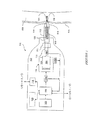
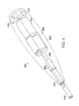
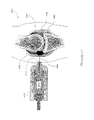
図1を参照すると、生体150の表面155を貫いて物質を輸送するために使用される例示的な無針式経皮輸送装置100の概略ブロック図が示されている。例えば、装置100は有効成分(例えば、薬物)の液体処方物を生体(農業用の動物または人など)に注入するために使用できる。代替的に、あるいはこれに加えて、同じ装置100を用いて、採取サンプルを体の表面155を通して装置内100に設けることができる外部リザーバまたはチャンバ113内に吸引することによって、生体150からサンプルを採取できる。
Referring to FIG. 1, a schematic block diagram of an exemplary needleless
装置100は、典型的には、必要に応じて表面155(例えば、皮膚)を貫通するのに必要とされる速度および直径で生体の表面155を通して物質を輸送するノズル114を備える。すなわち、ノズル114から噴出される物質がジェット噴流を形成し、ジェット噴流の力が貫入深さを決定する。ノズル114は一般に、皮膚に接触させて配置できるヘッド115などの平坦な表面と、オリフィス101とを有する。オリフィス101の内径が輸送される流れの直径を制御する。さらに、オリフィス101を形成する開口、または管腔103の長さによっても、輸送(例えば、注入)圧力が制御される。
The
好ましくは、生体表面155は、物質の輸送に先立って引き伸ばされる。最初に表面または皮膚を引き伸ばすことによって、そのようにしない場合に必要とされる力よりも少ない力を用いて皮膚を貫通することができる。これは、たるんだ風船を引き張られた風船と比べた場合に類似している。通常、たるんだ風船は、はるかに貫き通しにくい。
Preferably,
引き伸ばしは、単にノズル114を皮膚の表面155に押し込むことによって達成できる。いくつかの実施形態においては、輸送に先立って表面155が充分に引き伸ばされたことを確認するために、別個の表面参照センサまたは力トランスデューサが備えられる。このようなセンサをコントローラに接続し、好ましい表面特性が達成されるまで輸送を停止することができる。
Stretching can be accomplished by simply pushing the
いくつかの実施形態においては、標準的な皮下注射針が所定の長さに切断され、ヘッド115に結合される。針の一端は、皮膚に接するヘッド115の表面に対して同一面、あるいはわずかに引っ込んでおり、使用時に皮膚を突き刺すのを避けている。針の内径(例えば、100μm)が開口の直径を定め、針の長さ(例えば、5mm)ならびに開口寸法が、所定のアプリケータ圧力に対する結果として得られる注入圧力を制御する。別の実施形態においては、組立工程を削減するために、ヘッド115に孔を直接開けることができる。一般には、オリフィスの長さは例えば500μm〜5mmの範囲に選択可能であり、一方で、直径は50μm〜200μmの範囲にできる。特定の一実施形態においては、オリフィスの直径は約120μmである。
In some embodiments, a standard hypodermic needle is cut to a predetermined length and coupled to the
ノズル114は、シリンジ112(輸送される物質を一時的に貯蔵するためのリザーバ113を形成している)に接続できる。さらに、シリンジ112は、少なくとも遠位端がリザーバ113内にスライド可能に位置しているプランジャまたはピストン126を備える。プランジャ126がシリンジ112の縦軸に沿っていずれかの方向に移動することで、対応する圧力がリザーバ113内に生じる。いくつかの実施形態においては、シリンジ112は装置100と一体化されている。別の実施形態においては、シリンジ112は装置100と分離して取り付け可能である。市販の無針シリンジ112、例えば、カリフォルニア州San DiegoのEquidine Systems Inc.から入手できるモデル参照番号第100100号などのシリンジ112を、装置100に取り付けることができる。
The
ノズル114をシリンジ112または装置100の遠位端に着脱可能に結合することにより、それぞれが意図された用途に合わせて作製された種々のノズルを注入およびサンプル採取(すなわち、吸引)のために使用することができる。すなわち、サンプル採取ノズルが、管腔103の方に先細りになるより大きなオリフィス101を備えていてもよく、これにより、より効率的な採取またはより大量のサンプル採取を容易にすることができる。
By removably coupling the
有利には、制御可能なアクチュエータを使用して、チャンバ113に圧力を選択的に加えることができる。専用に設計された電磁アクチュエータ125が、高速立ち上がり時間(例えば、1ミリ秒未満)を有する高圧パルスを発生するように構成されている。アクチュエータ125は、高圧アクチュエータに依存して皮膚の下に処方物を注入する無針式注入装置に使用することができる。有利には、アクチュエータは動的に制御可能であり、動作中に圧力対時間の調節を可能にしている。別の無針式装置における電磁アクチュエータの少なくとも1つの利点は、比較的静かな動作にある。動作には、急激なばねの解放または気体の放出はなく、空隙内での自由に懸垂されたコイルの運動を含む。自由に運動するコイルを本明細書に記載の方法で動作させることで静かな動作が実現され、これは、投与の際に受け手および付近に存在する他者にとっての苦痛および不安を少なくすることに貢献するため、重要な特徴である。
Advantageously, a controllable actuator can be used to selectively apply pressure to the
さらに詳しくは、電磁アクチュエータ125は、物質の経皮輸送を達成するためにプランジャ126に加えられる線形力を発生するように構成されている。力の伝達は、ベアリング111によってスライド可能に結合された剛体ロッドなど、力伝達部材110によって達成できる。ロッド110のいずれかの端部を固定して、アクチュエータがいずれかの方向に移動することによってプランジャ126も移動するようにできる。ベアリングは、ロッド110の半径方向の移動を抑制する一方で、軸方向の移動を可能にする。
More particularly, the
いくつかの実施形態においては、アクチュエータ125は、磁石アセンブリ105などの静止構成要素、およびコイルアセンブリ104などの可動構成要素を備えている。コイルアセンブリ104内で発生した力を、直接的またはロッド110を介して間接的にプランジャ126に加え、物質の経皮輸送を達成することができる。一般に、アクチュエータ125、ベアリング111、およびシリンジ112は、動作の際にこれらの構成要素を支持して、固定位置に保持するフレームまたはハウジング102に結合されている。
In some embodiments, the
いくつかの実施形態においては、装置100は、装置の状態を示すユーザインタフェース120を備える。ユーザインタフェースは、装置の動作準備ができている旨の単純な表示を提供することができる。例えば、注入のための充分な条件が満足されたときに、コントローラ108に接続された発光ダイオード(LED)をオンにすることができる。より詳細な情報を提供するために、液晶表示装置(LCD)、冷陰極管(CRD)、電荷結合素子(CCD)、またはユーザと装置100との間で詳細な情報を伝達できる他の任意の適切な技法など、より高度なユーザインタフェース120を備えることができる。このように、ユーザインタフェース120はタッチスクリーンなどの装備を含み、これにより、作業者は1つ以上のパラメータについてのユーザ選択として入力を供給できる。この結果、ユーザは、投与およびサンプルに関するパラメータ、年齢および体重などといった生体に関するパラメータを特定することができる。
In some embodiments, the
電源106が、アクチュエータ125のコイルアセンブリ104への電気入力を供給する。以下にさらに詳しく説明されるように、磁石アセンブリ105により生成される磁界の存在下でコイルアセンブリ104に電流を供給することで、コイルアセンブリ104を作動させ、シリンジ112のプランジャ126に作用を及ぼすことができる機械的な力を発生させる。電磁アクチュエータは、装置の可搬性を裏付ける効率的な力トランスデューサである。さらに後に詳しく説明される例示的な装置は、約200マイクロリットルの流体を送出するために約50ジュールのエネルギーを消費する。ちなみに、標準的な9ボルトのバッテリーは、最大で約8,500ジュールを供給することができる。
A
コントローラ108が電源106とアクチュエータ125との間に電気的に接続され、これにより、コントローラ108は電源106からアクチュエータ125に供給される電気入力信号を選択的に供給、除去、および調節できる。コントローラ108は、ローカルインタフェースによって操作できる単純なスイッチであってよい。例えば、ユーザがハウジング102に設けられたボタンを操作して、電源106からアクチュエータ125への電気入力を選択的に供給および除去することができる。いくつかの実施形態においては、コントローラ108は、電源106からアクチュエータ125に選択的に電力を供給するように構成された電気回路などの制御要素を備えており、電気入力が選択された用途によって生成される。すなわち、電源106が実質的に一定または直流(D.C.)値を供給する単純な電池である実施形態においては、コントローラによって、異なる電気的な値、あるいは時間変化する電気的な値を供給することができる。いくつかの実施形態においては、コントローラ108は搭載マイクロプロセッサを含み、あるいは多機能な能力を提供する相互接続プロセッサまたはパーソナルコンピュータを含む。
A
いくつかの実施形態においては、無針式経皮輸送装置100は、リモート通信インタフェース118を備える。リモートインタフェース118を利用して、装置100の状態や装置100内に含まれている物質の状態などといった情報を、病院のコンピュータや薬物製造者のデータベースなどといった遠隔のソースに伝送できる。代替として、あるいはこれに加えて、リモートインタフェース118をコントローラ108と電気的に接続し、リモートインタフェース118を利用して、遠隔のソースから受け取った入力をコントローラ108に送り、アクチュエータ125を制御することができる。
In some embodiments, the needleless
リモートインタフェース118は、ローカルエリアネットワークインタフェース(例えば、イーサネット(登録商標))などのネットワークインタフェースを備えることができる。この結果、ネットワークインタフェースカードを利用することにより、別の装置またはユーザが、ローカルエリアネットワークに同じく接続されているパーソナルコンピュータを使用して、装置100に遠隔からアクセスすることができる。代替として、あるいはこれに加えて、リモートインタフェース118は、広域通信網インタフェースを備えることができる。これにより、別の装置またはユーザが、ワールドワイドウェブなどの広域通信網を介して、装置100に遠隔からアクセスできる。いくつかの実施形態においては、リモートインタフェース118は、公衆交換電話網を介して遠隔の装置/ユーザと接続できるモデムを備える。さらに別の実施形態においては、リモートインタフェース118は、無線で遠隔の装置/ユーザにアクセスするための無線インタフェースを備える。無線インタフェース118は、IEEE 802.11仕様にもとづく無線ローカルエリアネットワーク(WLAN)用のWi‐Fi標準、802.16(WiMAX)などといった802.11の仕様を超える新標準、ならびに他の無線インタフェース(ZigBeeなど、無線パーソナルエリアネットワーク(WPANs)用として小型の低電力デジタル無線装置を使用するように設計されたIEEE 802.15.4標準にもとづく高レベルの通信プロトコルセットを含む)など、標準的な無線インタフェースを使用することができる。
The
いくつかの実施形態においては、コントローラが、それぞれの物理的特性を検出する1つ以上のセンサから入力を受け取る。例えば、装置100は、選択された基準に対する物体の座標位置(例えば、コイルの位置)を示すのに使用される位置センサ116Bなど、トランスデューサを備える。同様に、変位量を用いて、1つの位置から他の位置までの特定の距離にわたる移動を表すことができる。有利には、検出されたパラメータを、プランジャ位置の表示、すなわち投与量の表示として用いることができる。いくつかの実施形態においては、さらに近接センサを使用して、装置の一部分(コイルなど)が限界距離に達したことを表示できる。これは、プランジャ126、力伝達部材110、または電磁アクチュエータ125のコイルアセンブリ104の位置を検出することによって達成できる。例えば、光エンコーダなどの光センサを用いてコイルの巻き数を数え、コイルの位置を決定できる。位置または変位の測定に適した他の種類のセンサとしては、誘導トランスデューサ、抵抗摺動接触式トランスデューサ、光ダイオード、および線形可変変位変圧器(LVDT)が挙げられる。
In some embodiments, the controller receives input from one or more sensors that detect respective physical characteristics. For example, the
力トランスデューサ116Aなどの他のセンサを用いて、アクチュエータ125によってプランジャ126に加えられる力を検出することができる。図示されるとおり、力トランスデューサ116Aを、コイルアセンブリ104の遠位端と力伝達部材110との間に配置し、トランスデューサ116Aによってアクチュエータ125が力伝達部材110に加える力を検出することができる。この部材110は剛体であるため、力はプランジャ126に直接伝達される。力がプランジャ126を動かし、対応する圧力をリザーバ113内に発生させる。プランジャ126をリザーバ113内に押し込む正の力が、リザーバ113内の物質をノズル114を通して押し出す正の圧力を生み出す。プランジャ126をノズル114から離れるように引き戻す負の力が、物質を装置の外部からノズル114を通してリザーバ113内に吸引する負の圧力または真空を生み出す。また、物質をアンプルから得ることも可能であり、リザーバ113を物質であらかじめ満たすために負圧が使用される。代替として、あるいはこれに加え、血液、組織、または他の間質液などのサンプル物質が生体から採取されてもよい。いくつかの実施形態においては、チャンバ内の物質に加えられる圧力を直接検出するために、圧力トランスデューサ(図示されていない)を設けることもできる。
Other sensors, such as
さらに、電気センサ116Cを設けて、アクチュエータ125に供給される電気入力を検出することもできる。電気センサ116Cは、1つ以上のコイル電圧およびコイル電流を検出できる。センサ116A、116B、116C(全体として、116)は、コントローラ108に接続され、検出された特性をコントローラ108に供給する。コントローラ108は、検出された特性のうちの1つ以上を用いて、電源106からアクチュエータ125への電気入力の供給を制御し、これにより、シリンジ112内に生成される圧力を制御して所望の輸送性能を実現できる。例えば、位置センサを用いてアクチュエータ125をサーボ制御し、コイルアセンブリ104を所望の位置にあらかじめ位置合わせし、位置合わせされたコイル104を安定させ、動作サイクルを完了させることができる。このように、第1位置から第2位置へのコイルアセンブリ104の移動が、対応する容積の物質の輸送に相当する。コントローラ108はプログラムされたプロセッサを備え、リザーバの物理的サイズを与える位置にもとづいて容積を計算できる。
Further, an
以下にさらに詳しく説明される動作サイクルでは、全体として、アクチュエータ125に電気入力を加えて物質の輸送を発生させ、電気入力を中止して物質の輸送を停止する。動的に制御可能な電磁アクチュエータ125にサーボ制御機能を組み合わせることで、動作サイクルの進行中に圧力を調節することが可能である。1つ以上のセンサ116を使用して、輸送すなわちサイクルの進行中に動作サイクルをさらに制御することができる。代替として、あるいはこれに加えて、1つ以上のローカルインタフェースまたはリモートインタフェースを用いて、動作サイクルをさらに制御することができる。
In the operation cycle described in more detail below, as a whole, an electric input is applied to the
いくつかの実施例においては、コントローラ108は、それぞれが生体表面の物理的特性を検出する1つ以上のセンサ(図示されていない)に接続することができる。この情報を用いてアクチュエータ125をサーボ制御し、注入圧力、したがって皮膚への薬物の進入深さを、特定の用途に合わせて調整することができる。例えば、装置100が幼児に使用される場合、センサが幼児の皮膚の柔らかさを検出し、コントローラ108が幼児の皮膚の特性を考慮に入れて、注入圧力を低下させる。注入圧力は、例えば、アクチュエータ125に加えられる電気入力信号ならびに/あるいは電流パルスの立ち上がり時間および/または継続時間を制御することによって調節可能である。成人または太陽によって皮膚を傷めた者について使用されるとき、コントローラは注入圧力を高めることができる。注入圧力を、体の皮膚の位置(例えば患者の顔対腕など)に応じて調節することができる。また、注入圧力は、薬物を皮膚の下に送達するように、あるいは深く筋肉組織に送達するように、調整できる。さらには、注入圧力は、時間とともに変化させることができる。例えば、いくつかの実施例においては、最初に大きな注入圧力を用いて薬剤で皮膚を貫通し、その後に低い注入圧力を用いて薬剤を送達することができる。また大きな注入圧力を用いて、チャンバまたは薬瓶を封じているシールを破壊することも可能である。
In some embodiments, the
さらに詳しくは、電源106は、装置100の外部にあってもよい。例えば、装置100は別個の電源に接続することもできる。しかし、好ましくは、装置100の可搬性を向上させるために、電源106は装置100に内蔵されている。このような可搬性は、特に、家畜類の治療あるいは遠隔地の人々または動物へのワクチンなどの薬剤の投与など、現場での用途に有用である。
More specifically, the
電源106は、汎用の9ボルトのバッテリーなど、交換可能な電池を含むことができる。あるいは、電源106は、充電式電池(例えば、ゲル電池、鉛酸蓄電池、ニッケル‐カドミウム電池、ニッケル水素電池、リチウムイオン電池、およびリチウムポリマー電池)など、充電可能な装置を備えている。いくつかの実施形態においては、電源106はストレージキャパシタを備えている。例えば、複数のキャパシタを、外部の電源などの別の電源によって充電することができる。
The
さらに詳しくは、電磁アクチュエータ125は、磁界に対して配置された導電コイルアセンブリ104を含み、これにより、コイル内に導入される電流と対応する機械的な力を発生する。この構成は、少なくとも原理的には、拡声器のボイスコイルアセンブリにおいて見られるものと同様である。すなわち、磁界と電流と発生する力との間の関係は明らかであり、一般にローレンツ力の法則と称されている。
More particularly, the
好ましくは、コイル104は、磁界がコイル104の1つ以上の巻きの方向に対してほぼ直角に向けられるように、磁界に対して位置合わせされている。したがって、磁界の存在下でコイル104内に導入される電流は、磁界およびコイルの両者に対して直交する方向(「右手の法則」と称される関係)の比例力を生成する。
Preferably, the
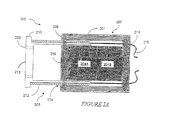
さらに詳しくは、電磁インパルス・アクチュエータ200の断面図が、図2Aに示されている。電磁アクチュエータ200は、環状の隙間214を形成している磁石アセンブリ205と、間隙214にスライド可能に配置されたコイルアセンブリ203とを備えている。コイル203のストロークは、コイルおよび磁石アセンブリの長さによって制御することができる。このようにして、電磁アクチュエータは、1回のストロークの持続中に、かなりの量の物質を輸送するように構成することができる。例えば、最大で300マイクロリットル以上の容積を、1回のストロークで輸送することができる。代替として、あるいはこれに加えて、薬瓶またはシリンジの全内容物を、複数の少ない投与量で輸送することができる。例えば、300マイクロリットルの薬瓶の実質的に全内容物を、それぞれが30マイクロリットルである10回の別個の注入により動物に輸送することができる。
More specifically, a cross-sectional view of
さらに、アクチュエータの可制御性により、精密な輸送が可能になる。例えば、物質を、約1%である最小の容積増分で生体に送出することができる。すなわち、200マイクロリットルの容積について、投与量を200ナノリットル刻みで調整できる。したがって、充分な容積で満たされた単一シリンジは、コイルへの電気入力を制御することによって、さまざまな量を送出できる。このようなアクチュエータの動作は確定的であり、さらに精密な制御に適している。 In addition, the controllability of the actuator allows for precise transport. For example, a substance can be delivered to a living body with a minimum volume increment that is about 1%. That is, for a volume of 200 microliters, the dosage can be adjusted in increments of 200 nanoliters. Thus, a single syringe filled with sufficient volume can deliver various amounts by controlling the electrical input to the coil. The operation of such an actuator is deterministic and suitable for more precise control.
磁石アセンブリ205は、中心軸に沿って配置された磁石204A、204Bの列を備えている。磁石の列を、1つ以上の磁石デバイスを重ねることによって生成できる。例えば、磁石デバイスは永久磁石であってもよい。磁界が強いほど、同じコイルにおいて発生する機械力はより大きいため、より強力な磁石が好ましい。可搬性および操作の容易性が、手持ちユニットとされる装置100にとって重要な特徴であるため、高密度磁石が好ましい。
The
このような種類の磁石の1つは、希土類磁石と称され、ネオジム‐鉄‐ホウ素磁石(例えば、Nd2Fe14B)としても知られている。この種類の磁石は、それらの質量に比べてきわめて強力である。現在入手可能なデバイスは、強さにおいて約N24〜約N54に分類され、Nの後ろの数字が磁気エネルギー積(単位は、メガガウス‐エルステッド(MGOe))を表している。特定の一実施形態においては、N50の磁石が使用される。磁石によって生成される磁界は、一般に磁力線208に従い、図示の構成においては中心軸を中心として回転対称である。
One such type of magnet is referred to as a rare earth magnet, also known as a neodymium-iron-boron magnet (eg, Nd 2 Fe 14 B). This type of magnet is very powerful compared to their mass. Currently available devices are classified in strength from about N24 to about N54, with the number after N representing the magnetic energy product (unit is Mega Gauss-Oersted (MGOe)). In one particular embodiment, N50 magnets are used. The magnetic field generated by the magnet generally follows the
軸方向の空洞を形成し、一端で閉じられている直円柱シェル201の一端に、磁石204A、204Bが取り付けられている。環状の隙間が、磁石204A、204Bとケースの内壁との間に残され、シェル201の他端は、開放されてアクセス可能である。例示的なシェル201は、約40mmの外径および約31.6mmの内径を備えて形成され、したがって壁の厚さは約4.2mmである。この実施形態において、磁石204A、204Bは円柱形であり、約25.4mmの直径を有する。
シェル201は、好ましくは、磁石204A、204Bによって生成される磁界の封入を促進するように構成された材料から形成される。例えば、シェル201を、強磁性体またはフェライトから形成することができる。このような強磁性体の1つとして、炭素鋼(米国鉄鋼協会(AISI) 1026の炭素鋼)と称される合金が挙げられる。さらに、同様の強磁性体からなる端部キャップ206が、磁石204A、204Bの他端に取り付けられて設けられる。端部キャップ206を設けることは、内部に磁界を封入するように作用し、端部キャップ206とシェル201の外壁との間に形成される環状の隙間の間で磁界が半径方向に向くようになる。端部キャップは一般にシェルの壁よりも厚く、磁界が上部の磁石204Aの端部にループを描いて入るときに、磁界の封じ込みを促進する。上述の例示的なシェル201の実施形態において、端部キャップ206の軸方向の厚さは約8mmである。
コイルアセンブリ203は、ボビン210の周囲に巻き付けられた銅線など、導電材料から形成されたコイル212を備えている。ボビン210は、円筒形であってもよく、コイル212と一緒に環状の空洞214内に嵌り込むような寸法とされる軸方向空洞を形成する。いくつかの実施形態においては、ボビン210は、環状の空洞214に近接して並ぶ端部において実質的に閉じられている。閉じられた端部が、図2Aのプランジャ214または力支持棒210を押す力支持面を形成する。
The
強力かつ軽量のコイルアセンブリ203は、無針式輸送など、大きい力を高速に発生する必要がある用途にとって好ましい。好ましくは、ボビンは、アルミニウムやガラス繊維強化エポキシ樹脂など、丈夫でかつ軽量の材料から形成される。このような種類のガラス強化エポキシの1つが、GAROLITE(登録商標)の商品名で販売されている。この系列から選択される適切な材料として、湿潤および乾燥の両者においてきわめて高い機械的強度、良好な誘電損失特性、および良好な耐電圧性を提供するG10/FR4材料が挙げられる。他の材料としては、種々のポリマーにより補強可能な鈍い金色のポリテトラフルオロエチレン(PTFE)化合物が挙げられ、これは、316ステンレス鋼、アルミニウム、軟鋼、真ちゅう、およびカリフォルニア州FullertonのProfessional PlasticsからRULON(登録商標)の商品名で市販されている他のプラスチックなどの柔軟な相手面に対して極めて良好に機能する。ボビン210は、環状の隙間に嵌り込むように薄肉とされている。さらに、ボビン210は、シェル201、磁石204A、204B、または端部キャップ206に接触しうる表面について、低い摩擦係数を有する必要がある。いくつかの実施形態においては、低摩擦コーティングを、ボビンに施すことができる。このようなコーティングとしては、PTFEなどのフッ化炭素類が挙げられる。
A strong and
一般には、ガラス繊維強化エポキシ樹脂などの非導電性材料が、アルミニウムなどの導電性材料よりも好ましい。磁界と交差して移動する導電性材料に生じる渦電流が、ボビンの移動に対抗する機械力を発生する。このような対抗力は、意図するコイルの動きに逆らい、効率の低下を招くことになる。絶縁材料は、このような渦電流の発生を低減または防止する。 In general, a non-conductive material such as glass fiber reinforced epoxy resin is preferable to a conductive material such as aluminum. Eddy currents generated in the conductive material moving across the magnetic field generate a mechanical force that opposes the bobbin movement. Such a counter force opposes the intended movement of the coil and causes a decrease in efficiency. The insulating material reduces or prevents the occurrence of such eddy currents.
薄肉のボビン210は、より狭い環状の隙間214を可能にし、隙間を横切る磁界の強度をより大きくする。コイル212に大きな電流が流れると、結果として、構造破壊(例えば、溶解)を引き起こす可能性のある大きな熱負荷を生じる可能性がある。他の軽量材料として、高温の用途に最適の機械加工可能なポリアセタール樹脂が挙げられる。
The
例示的な実施形態をさらに検討すると、ボビン210は、約27mmの外径、約26mmの内径、および約46mmの軸方向長さを有する。コイル212は、28ゲージの銅線をボビン210の周囲にコイルの長さ(約35mm)当たり約115巻数の割合で6層に巻き付けて構成され、結果として合計で約700の巻数を有する。1026炭素鋼とともにN50の磁石を使用すると、端部キャップ206は、約0.63〜0.55テスラ(端部キャップ206の中央から測定して半径方向外側に向かうにつれて小さくなる値)を含む。
Considering further exemplary embodiments, the
このように、コイル212を通って流れる電流は、端部キャップ206とシェル201の壁面との間に生成される磁界208に対して直角に位置する。この結果として、縦軸に沿った方向の力がコイルに生じ、力の方向は、電流の流れの方向に応じて決まる。上述の例示的な装置においては、約1ミリ秒の継続時間にわたってコイルに加えられる約100ボルトの電気入力、すなわち駆動電圧が、動作サイクルのうちの貫通段階を表す。輸送段階においては、より低い約−2ボルトの電気入力が加えられる。加えられる入力の極性は、この輸送段階が生体からサンプルを採取するサンプル段階であることを示している。
In this way, the current flowing through the
一般に、コイル212は、2つの電気リード216を通して電気入力信号を受け取る。シェル201は1つ以上の孔部218を備え、この孔部を通してリード216を電源106(図1)に導く。シェル201の閉鎖端は、コイルの移動の際に空気が通過できる1つ以上の追加の孔部を含むことができる。このような孔部がなく、コイル212と環状の隙間214との間の空隙の公差が比較的密である場合、圧力が上昇してコイルの運動を妨げる。代替として、あるいはこれに加えて、さらにボビン210が、動作時の減衰圧力の上昇をさらに抑える1つ以上の孔部220を有してもよい。
In general,
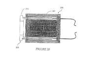
図2Aは、注入段階の後または最中のコイルアセンブリ203を示しており、コイルがシェル201から押し出され、前部プレート215を前方に送り出している。図2Bは、採取段階の後のシェル201内に引き込まれたコイルアセンブリ203を示しており、コイルアセンブリ203がシェル201内に引き込まれている。
FIG. 2A shows the
いくつかの実施形態においては、導電コイルが比較的大きな振幅の電流を流し、大きな力を発生して大きな圧力を生じるように構成されている。また、コイルは高周波動作を可能にするために比較的低インダクタンスを有し、高速の立ち上がり時間(すなわち、インパルス)の応答を可能にしている。いくつかの実施形態においては、コイルのインダクタンスは100ミリヘンリー未満である。好ましくは、コイルのインダクタンスは約50ミリヘンリー未満である。さらに好ましくは、コイルのインダクタンスは約10ミリヘンリー未満である。例えば、コイルのインダクタンスは、約5〜10ミリヘンリーの間であってもよい。低インダクタンスで大電流容量を提供する1つの方法は、少数の巻数(例えば、1〜3回)で構成された太い直径の導体で形成されたコイルを使用することである。 In some embodiments, the conductive coil is configured to pass a relatively large amplitude current and generate a large force to generate a large pressure. In addition, the coil has a relatively low inductance to enable high frequency operation, enabling a fast rise time (ie, impulse) response. In some embodiments, the inductance of the coil is less than 100 millihenries. Preferably, the inductance of the coil is less than about 50 millihenries. More preferably, the inductance of the coil is less than about 10 millihenries. For example, the inductance of the coil may be between about 5-10 millihenries. One way to provide a large current capacity with low inductance is to use a coil formed of a large diameter conductor composed of a small number of turns (eg, 1-3 turns).
結果として、高速の立ち上がり時間の高圧のパルスを生成できる圧力アクチュエータが得られる。さらに、アクチュエータの動作は、アクチュエータの物理的特性および入力電流に応じて、制御可能かつ高度に予測可能である。さらにまた、アクチュエータは可逆であり、コイルの電流の方向に応じて両方向に力を発生することができる。 The result is a pressure actuator that can generate high pressure pulses with fast rise times. Furthermore, the operation of the actuator is controllable and highly predictable depending on the physical characteristics of the actuator and the input current. Furthermore, the actuator is reversible and can generate forces in both directions depending on the direction of the coil current.
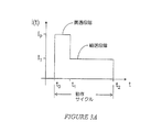
さらに、この可制御性は注入プロファイルを調整可能にし、このプロファイルは、皮膚の外側層を破壊する高速の高圧パルス、およびその後に処方物を送出するための低圧の長いパルスを含むことができる。図3Aを参照すると、時間変化する例示的な電気入力が示されている。曲線が、アクチュエータ125のコイルアセンブリ104に供給される電流の変化を表している。最初の時点t0において、コイル104に電流が供給される。電流が、休止値(例えば、0アンペア)から最大値IPに立ち上がり、選択された継続時間にわたってこの最大値を維持し、その後に時刻t1において別の電流値ITに移行している。電流の振幅は、後の時刻t2まで実質的にこの値を維持しても、あるいは時間とともに変化を続けてもよく、時刻t2において電流は休止値に戻る。
In addition, this controllability allows the infusion profile to be adjusted, and this profile can include a high-speed high-pressure pulse that breaks the outer layer of the skin, followed by a low-pressure long pulse to deliver the formulation. Referring to FIG. 3A, an example electrical input that varies with time is shown. The curve represents the change in current supplied to the
時刻t2およびt0の間に画定された全期間を、動作期間または動作サイクルと称することができる。ここで述べた電流入力に類似の形状を有する電流入力に関しては、時刻t1およびt0の間に画定された期間を、貫通段階と称することができる。その名が示しているとおり、大きな電流値IPが、相応して高い圧力を生じさせ、この圧力を針またはランセットを使用することなく生体表面を貫通するために使用することができる。時刻t2およびt1の間に画定された動作サイクルの残りの部分を、輸送段階と称することができる。この名称が示しているとおり、比較的小さな電流値ITが、より低い圧力を生じ、この圧力を利用して、貫通段階において生成された表面の孔を通ってリザーバ113(図1)から生体に物質を輸送することができる。
The entire period defined between times t 2 and t 0 can be referred to as an operating period or operating cycle. For a current input having a shape similar to the current input described here, the period defined between times t 1 and t 0 can be referred to as a penetration stage. As its name implies, a large current value I P can cause higher pressure correspondingly, it is possible to use this pressure to penetrate the surface of a living body without using a needle or lancet. The remaining portion of the operating cycle defined between times t 2 and t 1 can be referred to as the transport phase. As the name suggests, a relatively small current value I T is generated a lower pressure, by utilizing this pressure, the biological from the
電気入力に応答してリザーバ113(図1)内に生じる圧力の例示的なグラフが、図3Bに示されている。図示されるように、圧力が時刻t0において、おそらくは電気コイルの伝達特性に起因するわずかな遅延Δを伴い、初期の休止値から極大値PPに上昇する。この圧力値を、図1に関して上述したとおり、ジェット噴流の生成に利用することができる。輸送段階においては電流が減少するため、圧力も同様に、物質について所望の輸送を達成するように定められたより小さな値PTに低下する。輸送段階は、所望の量の物質が輸送されるまで続き、次いで圧力が取り除かれて、動作サイクルが完了する。 An exemplary graph of pressure generated in reservoir 113 (FIG. 1) in response to electrical input is shown in FIG. 3B. As shown, the pressure at time t 0, perhaps with a slight delay Δ resulting from the transfer characteristics of the electrical coil rises from an initial rest value to the maximum value P P. This pressure value can be used to generate a jet jet as described above with respect to FIG. Since the current decreases during the transport phase, the pressure will similarly drop to a smaller value PT defined to achieve the desired transport for the material. The transport phase continues until the desired amount of material has been transported and then the pressure is removed to complete the operating cycle.
サーボ制御の注入器は、サーボコントローラと組み合わるにように構成された専用設計の電磁圧力アクチュエータを備え、1つ以上の物理的特性(例えば、圧力、位置、容積、など)にリアルタイムに応答する注入圧力を生成する。いくつかの実施形態においては、サーボ制御の注入器は、無針式装置である。電磁圧力アクチュエータが、皮膚の下に処方物を注入するために、高速の立ち上がり時間(例えば、1ミリ秒未満)を有する高圧パルスを生成する。このような高速の立ち上がり時間により、輸送全体を約10ミリ秒未満で完了させることができる。アクチュエータによって提供される圧力は、所望の結果を達成するために、単一の注入動作の最中に変化させることができる。例えば、最初に第1の高圧力を処方物に与えて、動物の皮膚の外側表面層を貫通する。ひとたび皮膚を貫通すると、注入の残りの部分に対して、圧力を第2のより低い圧力に下げる。サーボコントローラを用いて、チャンバ内の圧力の変化を検出することによっていつ皮膚が貫かれたのかを決定し、それに応じて注入圧力を制御することができる。 Servo-controlled injectors have a specially designed electromagnetic pressure actuator configured to be combined with a servo controller and respond in real time to one or more physical characteristics (eg, pressure, position, volume, etc.) Generate injection pressure. In some embodiments, the servo-controlled injector is a needleless device. An electromagnetic pressure actuator generates a high pressure pulse with a fast rise time (eg, less than 1 millisecond) to inject the formulation under the skin. With such a fast rise time, the entire transport can be completed in less than about 10 milliseconds. The pressure provided by the actuator can be varied during a single injection operation to achieve the desired result. For example, a first high pressure is first applied to the formulation to penetrate the outer surface layer of the animal's skin. Once through the skin, the pressure is reduced to a second lower pressure for the remainder of the infusion. A servo controller can be used to determine when the skin has been penetrated by detecting a change in pressure in the chamber and to control the infusion pressure accordingly.
サーボコントローラ108は、1つ以上のセンサ116から入力信号を受け取り、所定の関係に従って出力信号を発生する。サーボコントローラの出力を用いて、制御可能なアクチュエータを駆動する電流の振幅を制御することによって、圧力を制御できる。
リアルタイム制御は、センサ116からの入力を繰り返し受け取り、それらの入力を所定の関係に従って処理し、対応する出力を発生するサーボコントローラ108によって達成可能である。注入の間に注入圧力を調節するために、検出‐制御のプロセス全体が、注入期間の最中に多数回実行されなければならない。例えば、サーボコントローラ108は、センサから受け取った信号を処理して、対応する出力信号を100kHzの速度(すなわち、10マイクロ秒ごと)で高速に供給できる高速マイクロプロセッサを備えている。このような高速応答時間は、単一の5〜10ミリ秒の注入の間に数百回の圧力調節の機会を提供する。
Real-time control can be achieved by
コイルアセンブリ104の摩擦または抗力が効率低下を引き起こすため、コイルを磁石アセンブリ105の空洞内で浮動させることができる。すなわち、コイルアセンブリ104が隙間内で浮遊し、自由に移動することができる。コイルアセンブリ104に電流が供給されていない状態では、コイルアセンブリは装置100の動きとともに前後にスライドできる。このような動きは、物質をリザーバから意図せず流出させることがあり、あるいはリザーバに空気などの物質を導入することがあるため、望ましくないと考えられる。位置センサ116Bを備えるサーボコントローラを使用し、コイル104の位置を調整することによって、コイルアセンブリ104に供給される電気入力信号から生じる反対向きで等しい力を加えることによって、外力(例えば、重力)の存在下でコイルを所定の位置に保持することができる
Because the friction or drag of the
代替として、あるいはこれに加えて、アクチュエータを、処方物を収容するチャンバを形成するベローズに結合することができる。いずれの構成においても、動作の結果としてチャンバ内に圧力が生じ、チャンバがノズルを通じて処方物を押し出す。 Alternatively or in addition, the actuator can be coupled to a bellows that forms a chamber containing the formulation. In either configuration, pressure is created in the chamber as a result of operation, and the chamber pushes the formulation through the nozzle.
動的制御可能な無針式注入装置400の例示的な実施形態が、図4に示されている。装置400は、制御可能な電磁アクチュエータ402を、一端を押し棒406に当接させて備えている。押し棒406の軸は、アクチュエータ402の縦軸と同一線上にあり、ベアリング408を通ってスライドして半径方向の動きを抑制する。シリンジ410を取り付けるための取付けアダプタ412が、装置400の遠位端に設けられている。シリンジのプランジャ(図示されていない)が、取付けアダプタ412の内部に位置し、押し棒406の他端に当接している。充電可能キャパシタ415などの電源が、アクチュエータ402内に電流を導入するため、アクチュエータ402の近くに配置されている。さらに、装置400は、注入を開始するボタン414、およびアクチュエータ402への電源の供給を制御するコントローラ416を備えている。さらに、細長い成型プラスチックケース418などのハウジングが、種々の構成部品を相互に固定するために設けられている。
An exemplary embodiment of a dynamically controllable
より小型の動的制御可能な無針式注入装置500の例示的な実施形態が、図5に示されている。装置500は、小型電磁アクチュエータ502を備えており、電磁アクチュエータ502は、シリンジ508のプランジャ506の近位端に当接する遠位側の押し板504を有する。さらに、装置500は、シリンジ508の近位端が結合される取付け部材512を備えている。電源514も、アクチュエータ502の近くに配置されており、これら種々の構成要素が、ハウジング516内で相互に固定されている。いくつかの実施形態においては、図6に示すように、プランジャ528をコイルアセンブリ505に着脱可能に固定するために、接続具525が設けられている。これは、プランジャがコイルアセンブリ505の動きに応じていずれかの方向に移動することを保証する。
An exemplary embodiment of a smaller, dynamically controllable
さらに詳しくは、図6を参照すると、小型の制御可能な電磁アクチュエータ502が、中央の磁気コア520を強磁性体の端部キャップ506で覆われた強磁性体シェル522を備えている。コイルアセンブリ505が、磁石アセンブリの環状の隙間にスライド可能に配置されており、隙間内で自由に浮動する。シェル522の遠位端が、シェル522の遠位端の近くから続いて遠位側の取付けプレート512で終わる1つ以上の延長部524を備えている。しかし、図1および4の装置と対照的に、電磁アクチュエータ502は、別個のベアリング111、408を備えていない。代わりに、延長部524を含むシェル522の内表面が、コイルアセンブリ505に静止ベアリング面を提供し、軸方向の動きを可能にすると同時に、半径方向の動きを抑制する。第1のベアリング面550が、コイルアセンブリの遠位端に沿って画定される。第1のベアリング面550が、動作の際に延長部524の内表面に接してスライドする。いくつかの実施形態においては、第2のベアリング面555が、コイルアセンブリ505の近位部分に設けられる。第2のベアリング面555は、動作の際にシェル522の内表面に接してスライドする。
More specifically, referring to FIG. 6, a small controllable
延長部524は、図示のとおり、隣接する延長部524の間に開口を備え、重量を軽減するとともに、コイルの移動の促進および冷却のために空気の流れを促進することができる。この構成では、遠位側の取付けプレート512をシェル522に固定結合し、アクチュエータ502の剛性を高め、装置の動作によって生じるハウジング516(図5)への応力/ひずみの負荷を実質的に除去、または軽減している。
As shown, the
典型的な小型のローレンツ力アクチュエータ602の後方からの斜視図が、図7に示されている。電磁アクチュエータ602は、外側シェル622を有する磁石アセンブリを備えている。コイルアセンブリ605が、シェル622の内部にスライド可能に配置され、軸方向に平行移動するように構成されている。複数の縦方向の延長部624が、シェル622を取付けプレート612に結合するように構成されて、軸の周囲に配置されている。隣接する延長部624の間に開口が設けられている。シリンジ608が、電磁アクチュエータ602の遠位端において取り付けプレート612に結合されている。1つ以上のガイド626を設けてコイルの回転を防止し、それぞれのガイド626は、隣接する延長部624の内縁に沿って移動する。電磁アクチュエータ602の近位端は、コイルのリード616を通す孔部618と、動作の際に空気の流れを促進するための1つ以上の別の孔部620とを備えている。いくつかの用途においては、サンプル採取と注入との間に、サンプルの薬瓶が薬剤の薬瓶と交換される。代替として、あるいはこれに加えて、サンプルの分析を別個の分析器によって実行することも可能である。
A rear perspective view of a typical small
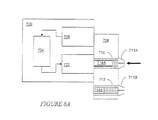
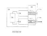
ローレンツ力アクチュエータは双方向性であるため、コイルの電流方向に応じて、物質の注入に使用される同じ装置を、サンプルの吸引にも使用することが可能である。これは、装置によってサンプルの採取を行うことができるため、有益な特徴である。図8Aを参照すると、例示的なサンプル採取の無針式注入器700が示されている。サンプル採取の注入装置700が、一端において第1のピストン714Aに当接している双方向の電磁アクチュエータ702を備えている。サンプル採取ノズル711Aが、シリンジ710の他端に結合されている。アクチュエータ702は、電池や適切に充電されたストレージキャパシタなどといった電源704によって駆動される。第1ピストン714Aがサンプル採取シリンジ710の内部にスライド可能に配置されており、これにより、アクチュエータ702に電気入力信号が供給されたときに第1ピストン714Aがサンプル採取ノズル711Aから離れて引き込まれる。動作の際にサンプル採取ノズル711Aを体の表面に接触させて置くと、生体からサンプルを採取することができる。
Because Lorentz force actuators are bidirectional, the same device used for material injection can also be used for sample aspiration, depending on the current direction of the coil. This is a useful feature because the sample can be taken by the device. Referring to FIG. 8A, an exemplary sampled
次に、図8Bを参照すると、サンプルが採取された後、可動のシリンジ取付け具708を用いて、サンプル採取シリンジ710が分析器706に整列するように配置し直すことができる。この同じ動きによって、第2のピストン714Bを有し、かつ薬物などの物質を含んでいる第2シリンジ712が、アクチュエータ702に位置合わせされる。取付け具708は、縦軸を中心として回転する回転式取付け具であってもよく、あるいは図示のような直線移動する取付け具であってよい。分析器706は、分析されたサンプルに応じて電源704に制御信号を提供する。制御信号によって、アクチュエータ702が第2ピストン714Bを前方に押し、分析したサンプルに応じた量の物質を押し出す。このようにして、同じ装置700を、サンプルの採取および物質の注入の両方に使用できる。
Referring now to FIG. 8B, after the sample has been collected, the
すでに述べたとおり、無針式装置を、体からサンプルを採取するために使用することができる。例示的なサンプル採取方法が、図9Aのフロー図に示されている。最初に、無針式注入器を用いて表面に孔が開けられる(ステップ800)。次いで、この無針式装置を再び使用して、生体からサンプルが採取される(ステップ810)。採取されたサンプルを分析して、例えば血糖などの物理的特性を決定する(ステップ820)。多数の異なる分析方法のいずれか1つ以上を、このステップにおいて実行することができる。例えば、分析として、(i)グルコースオキシダーゼ検査など、グルコースの検出のための電気化学的技法、および表面増感ラマン分光法などといった光学的技法を挙げることができる。コントローラが、分析の結果を受け取り、サンプルの分析結果にもとづいて投与量を決定する(ステップ830)。決定された投与量が、無針式装置を使用して生体に投与される(ステップ840)。 As already mentioned, a needleless device can be used to take a sample from the body. An exemplary sampling method is shown in the flow diagram of FIG. 9A. Initially, the surface is pierced using a needleless injector (step 800). The needleless device is then used again to collect a sample from the living body (step 810). The collected sample is analyzed to determine physical characteristics such as blood glucose (step 820). Any one or more of a number of different analysis methods can be performed in this step. For example, the analysis can include optical techniques such as (i) electrochemical techniques for the detection of glucose, such as a glucose oxidase test, and surface-sensitized Raman spectroscopy. The controller receives the results of the analysis and determines a dose based on the results of the sample analysis (step 830). The determined dose is administered to the living body using a needleless device (step 840).
さらに詳しくは、図9Bのフロー図を参照すると、無針式のサンプル採取のステップ(ステップ810)は、最初に皮膚を貫通するために物質を注入することを含む(ステップ812)。例えば、皮膚を貫通するために、生理食塩水を注入することができる。次いで、無針式装置を使用し、生体から装置のリザーバ内にサンプルを吸引することによって、サンプルが抽出または採取される。サンプルの容積または組成が不充分である場合、生理食塩水ならびに血液、組織、および間質液からなる吸引されたサンプルは、無針式装置を使用して生体内に再注入される(ステップ818)。ステップ814〜818は、適切なサンプルまたはボーラスが得られるまで繰り返すことができる。いくつかの実施形態においては、サンプルが充分であるか否かの判断を、所定のサイクル数に応じて前もって決定できる。代替として、あるいはこれに加えて、サンプルが充分であるか否かを、サンプル採取のプロセスの間に決定することもできる。 More particularly, referring to the flow diagram of FIG. 9B, the needle-free sampling step (step 810) includes first injecting a substance to penetrate the skin (step 812). For example, physiological saline can be injected to penetrate the skin. The sample is then extracted or taken using a needleless device by aspirating the sample from the living organism into the reservoir of the device. If the sample volume or composition is insufficient, the aspirated sample of saline and blood, tissue, and interstitial fluid is reinjected into the living body using a needleless device (step 818). ). Steps 814-818 can be repeated until a suitable sample or bolus is obtained. In some embodiments, the determination of whether a sample is sufficient can be determined in advance according to a predetermined number of cycles. Alternatively or in addition, whether the sample is sufficient can be determined during the sampling process.
動的制御可能な電磁アクチュエータに供給できる例示的な駆動電流が、図10Aおよび10Bのグラフに示されている。最初に図10Aを参照すると、初期の貫通段階を含む駆動サイクル例が示されており、この貫通段階では、物質を生体に送出して孔を生成するために大きな正の電流が印加される。貫通段階の後にサンプル採取段階が続き、サンプルを採取するために、より小さい電流が反対方向に加えられる。次に図10Bを参照すると、初期の貫通段階に続いて、図9Bに関して説明したサンプル採取の段階および再注入の段階が繰り返される多サイクルの例が示されている。 Exemplary drive currents that can be supplied to a dynamically controllable electromagnetic actuator are shown in the graphs of FIGS. 10A and 10B. Referring initially to FIG. 10A, an example drive cycle is shown that includes an initial penetration stage, in which a large positive current is applied to deliver a substance to the living body to create a hole. The penetration phase is followed by the sampling phase, and a smaller current is applied in the opposite direction to collect the sample. Referring now to FIG. 10B, an example of a multi-cycle is shown in which the initial penetration phase is followed by the sampling and reinjection phases described with respect to FIG. 9B.
サンプル採取注入装置900の別の実施形態が、図11に示されている。装置900は、それぞれが装置の両端に位置している2つのノズル914A、914Bを備えており、それらの間に制御可能な電磁アクチュエータ925が配置されている。各ノズル914A、914Bが、それぞれのシリンジ912A、912Bの外側端に接合されており、各シリンジは、それぞれのリザーバ913A、913Bを形成するとともに、内部にスライド可能に配置されたそれぞれのピストン910A、910Bを有する。各ピストンの内側端はアクチュエータ925のそれぞれの端部に結合され、これにより、一方向への動作によって一方のプランジャ910Aが遠位側のノズル914Aの方向に押し出され、内部に収容された物質を注入するように構成されたリザーバ913A内に圧力を生成する。同じ方向の同じ動作によって、他方のプランジャ910Bが遠位側のノズル914Bから離れて引き込まれ、リザーバ913B内に真空を発生して物質をリザーバ913B内に吸引する。
Another embodiment of a sample collection and
アクチュエータ925は、可動のコイルアセンブリ904を備えており、電源909に接続されているコントローラ908から電気入力信号を受け取る。いくつかの実施形態においては、装置900は、サンプル採取リザーバ913Bに収集されたサンプルを分析するため、コントローラ908に接続された分析器916を備える。動作時には、生体表面を貫く無針式輸送の結果として、装置の一端を用いて生体からサンプルを採取できる。分析器916は、サンプルを分析し、結果をコントローラ908に提供できる。コントローラ908は、分析されたサンプルにもとづき、生体への物質の投与についてのパラメータを決定できる。
The
装置の他端を用いて、ある一定の投与量の物質を生体に投与できる。このとき、コントローラは、おそらくは入力/出力インタフェースを介して現場または遠方の作業者の制御のもとで、電源909からアクチュエータ925に電気入力を供給する。アクチュエータ925が、受け取った入力に従って同じ方向にピストンを移動させ、圧力を生成して、装置900の注入端を通しての注入を可能にする。
The other end of the device can be used to administer a certain dose of substance to the body. At this time, the controller provides an electrical input to the actuator 925 from the
いくつかの実施形態においては、有利には、複数回の注入および/またはサンプル採取を連続して実行できる制御可能な無針式注入装置1000を提供する。この結果、動作サイクルが、比較的短い隣接サイクル間の時間遅延をともなって生じる。このような装置は、多数回放出(マルチショット)無針式注入装置と称することができる。多数回放出による注入は、10ミリ秒の動作(すなわち、注入)サイクルで30ミリ秒〜50ミリ秒のうちに行うことができる。多数回放出のいくつかの装置は、薬瓶当たり最大500回の注入を送出する能力を有する。
In some embodiments, there is advantageously provided a controllable
例えば、図12の概略図を参照すると、多数回放出の無針式注入装置1000に、リザーバまたはアンプル1002が取り付けられている。装置1000が生体1004の表面に接して置かれ、経皮的な輸送が、装置1000の先端が置かれた第1の位置1006において開始される。このプロセスを、相互に略近接した他の位置において繰り返し、生体の大きな表面領域1008を処置することができる。他の用途においては、同じ多数回放出装置1000を使用して、多数の異なる生体のそれぞれにおいて物質を経皮的に輸送することができる。そのような用途として、一群の動物への連続的な接種を挙げることができる。
For example, referring to the schematic of FIG. 12, a reservoir or
多数回放出の用途における例示的なコイル駆動電流対時間のグラフが、図13に示されている。個々の動作サイクルまたは動作期間の電流プロファイルは、図3、10A、および10B(ユーザによる選択可能な放出間の遅延によって区別されている)に関して先に説明した電流プロファイルのいずれかと同様であってよい。各サイクルについて同一の全体的な入力波形が示されているが、装置は、各サイクルについて異なる波形を開始することも可能である。 An exemplary coil drive current vs. time graph for multiple emission applications is shown in FIG. The current profile for an individual operating cycle or period of operation may be similar to any of the current profiles previously described with respect to FIGS. 3, 10A, and 10B (distinguishable by a delay between user selectable emissions). . Although the same overall input waveform is shown for each cycle, the device can also start a different waveform for each cycle.
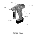
例示の可搬式多数回放出注入装置1100が、図14Aおよび14Bに示されている。装置1100は、ハンドル部1104を有するハウジング1102を備えており、ハンドル部1104に引き金1110を備えることができる。さらに装置は、ノズル1106、リザーバまたはアンプル1112、ならびに内蔵電源1108を備えている。いくつかの実施形態においては、装置1100は、さらにユーザインタフェース1114を備えている。
An exemplary portable
さらに詳しく電源106を参照すると、充電式電池またはストレージキャパシタなど、充電可能な電源を充電することが可能である。例えば、充電は、太陽電池、ダイナモ、または誘導結合によって実現できる。例えば、コイルアセンブリ104を、外部の電源に誘導結合して使用することができ、結合された電源が、コイルアセンブリ104内に電源106の充電に利用できる電流を発生させる。
Referring to
いくつかの実施形態においては、装置を、電磁アクチュエータ125自身を使用して充電できる。すなわち、磁石アセンブリ105によって生成される磁界を通してコイルアセンブリ104を機械的に動かす(装置100を揺動または振動させることによって達成できるように)ことで、コイル内に電流が生成される。コイルアセンブリ104を、レギュレータまたは他の適切な充電回路を介して、電源106に接続することができる。すなわち、磁界を通過してコイルアセンブリ104を動かすことによってコイルアセンブリ104に発生する電流を、電源106の充電に使用できる。
In some embodiments, the device can be charged using the
例示的な機械式充電装置が、図15に示されている。機械式充電ユニット1200は、軸1206を往復振動させる加振器1204などの機械的トランスデューサを備えている。軸の一端が、加振器1204に結合され、他端は、装置1201の力伝達部材110に係合するアダプタ金具1208に結合されている。さらに、充電ユニット1200は、充電期間において装置を加振器1204との係合状態に保持する取付けフランジ1202を備える。図示のとおり、まずシリンジが取り除かれ、これによりコイルアセンブリが磁界を通して振動し、コイル104に電流を発生させることができる。生じた電流を、電力調整器1210を通して電源106に供給できる。電力調整器1210は、1つ以上の整流器、電圧調整器、フィルタ、および充電ユニットを備えることができる。図示のとおり、磁石アセンブリ105は、運動するコイルアセンブリ104に対して磁石が固定されて維持されるように、取付け具1211を介してハウジング102に結合されている。
An exemplary mechanical charging device is shown in FIG. The
このような経皮輸送装置の制御可能な特性は、自動注入またはロボットによる注入に適している。第1に、強力な無針式注入を使用して、乳牛などの大型の哺乳類の比較的厚い皮など、生体の皮膚を通して注入することができる。注入が無針であるため、注入の最中に動物が動いても、動物の体内で針が破損することがない。さらに、強力な無針式注入を数分の1秒で達成できるため、動物が動いてはならない時間の長さが、大幅に短縮される。すなわち、単にノズルを動物に押し付け、瞬間的に放出を行うだけでよく、動物が動いている間に行うことさえ可能な短い時間期間で行うことが可能である。 The controllable properties of such transdermal delivery devices are suitable for automatic injection or robotic injection. First, powerful needleless injection can be used to inject through living skin, such as the relatively thick skin of large mammals such as dairy cows. Since the injection is needle-free, even if the animal moves during the injection, the needle will not break in the animal's body. Furthermore, because the powerful needleless injection can be achieved in a fraction of a second, the length of time that the animal must not move is greatly reduced. That is, simply press the nozzle against the animal and release it instantaneously, and it can be done in a short period of time that can even be done while the animal is moving.
制御された量の物質を動物に投与するための例示的な無針式注入システムが、図16に示されている。このシステムは、延長可能なアーム1304の遠位端に配置された無針式経皮輸送装置1306を備えている。アーム1304の近位端を、柱またはフレーム1308などの剛体の取付け部に接続することができる。さらに、センサ1310を設けて、経皮的輸送の実行に先立って動物を識別することもできる。例えば、動物1302が、バーコードタグまたは無線識別(RFID)タグなどといった識別マーク1312を備えることもできる。したがって、センサ1310は、バーコードまたはRFIDタグを読み取るように構成された質問器を備えることができる。センサ1310および経皮輸送装置1306は、どちらもコントローラ1314に接続されており、コントローラ1314はプロセッサを備えることができる。電源1316も、コントローラ1314を介して経皮輸送装置1306に接続されている。
An exemplary needleless infusion system for administering a controlled amount of substance to an animal is shown in FIG. The system includes a needleless
いくつかの実施形態においては、装置は、床反力センサ1318などの動物の物理的特性(体重など)を検出する別の動物用センサを備えている。識別および投与の際に動物1302を適切に位置させるため、ゲート1324などの案内を設けることができる。さらに、コントローラ1314は、センサ1318から入力を受け取り、動物の識別および体重にもとづいて投与量の制御を実行する。例えば、特定の動物に対し、識別および体重にもとづいて成長ホルモンを投与することができる。
In some embodiments, the apparatus includes another animal sensor that detects an animal physical property (such as body weight), such as a floor
いくつかの実施形態においては、システムはさらに、通信インタフェース1320を備える。通信インタフェースは、図1に関して上述した無線通信インタフェースなどの無線インタフェース1322を備えることができる。したがって、システムは、遠隔のユーザ、プロセッサ、および/またはデータベースと通信できる。
In some embodiments, the system further comprises a
動的制御可能なローレンツ力アクチュエータによって提供される動作機能が、多数かつさまざまな処置の選択肢を可能にしている。強力な注入能力と可制御性との組み合わせにより、同じ制御可能な無針式経皮輸送装置を、さまざまな注入物を送出するのに使用できる。例えば、装置を、表面層または皮膚への種々の生体層間(例えば、卵割面に沿って)の皮内投与のために、あるいは表皮および真皮の下の皮膚層である皮下組織に投与される皮下注入のために、非侵襲的に使用することができる。非軸方向の無針式注入が、代理人事件番号第0050.2093-000号による2006年2月10日付の発明の名称「Surface Injection Device(表面注入装置)」の米国特許出願に記載されており、本出願の全内容は参照により本明細書に引用したものとする。この装置を用いて、物質を筋肉に直接投与する筋肉注射を行うこともできる。またさらには、この装置は、薬物を静脈を介して血流に直接投与する静脈内注射に使用することも可能である。 The motion function provided by the dynamically controllable Lorentz force actuator allows for a number of different treatment options. Due to the combination of powerful infusion capability and controllability, the same controllable needleless transdermal delivery device can be used to deliver a variety of infusions. For example, the device is administered for intradermal administration of various biological layers (eg, along the cleavage plane) to the surface layer or skin, or to the subcutaneous tissue that is the skin layer below the epidermis and dermis It can be used non-invasively for subcutaneous injection. Non-axial needleless injection is described in a US patent application entitled “Surface Injection Device” dated February 10, 2006 by agent case number 0050.2093-000, The entire contents of this application are hereby incorporated by reference. This device can also be used for intramuscular injection where the substance is administered directly into the muscle. Still further, the device can be used for intravenous injection in which drugs are administered directly into the bloodstream via veins.
物質を関節に注入する例示的な用途が、図17に示されている。人の膝1400の一部分が、滑膜関節1402の例として示されている。滑膜関節1402は、「滑」膜1404または「関節」包の内部に封入された粘液1406を含んでいる。いくつかの処置においては、物質を粘液1406に注入することが望まれる。これは、滑膜1404をも貫通する比較的深い注入を必要とする。これまでのところ、このような注入においては、針の曲がりまたは破損を防ぐため、太い針を使用する必要がある。不利な点は、直径の大きな針は、患者の苦痛および不快を大きくする傾向にある。制御可能な電磁式無針装置を使用することにより、このような注入を実行して、物質1414を送出することが可能である。すなわち、シリンジ1408に貯蔵された物質1414が、ノズル1412を通って吐出される。ノズル1412によって細いジェット噴流が形成され、物質の流れ1416を直線経路に沿って所望の深さに導く。このようにして、より少ない苦痛で、曲げを生じることなく、流れ1416を滑膜1404を通して関節1402の内部領域に導き、物質1418を送達することができる。
An exemplary application for injecting material into a joint is shown in FIG. A portion of a
図18に示されている制御可能な無針式注入装置1800の別の実施形態は、内部にリザーバを形成するベローズ1802を備える。電磁アクチュエータ1825が、入力電流の方向に応じて、ベローズ1802を圧縮し、あるいは膨張させる。無針式注入に適合するノズル1801がベローズ・チャンバ1802に連通し、ベローズ1802が圧縮されたときに、チャンバ1802内に収容された処方物がノズル1801を通って押し出される。ノズル1801は、通常はアクチュエータ1825の静止部分に対して固定された関係に保持され、ベローズがアクチュエータ1825の可動部分とノズル1801との間で圧縮される。
Another embodiment of the controllable
ベローズ・チャンバ1802は、注入装置1800内で迅速かつ容易に取り外しおよび交換されるように構成することができる。例えば、ベローズ・チャンバ1802の挿入および取り外しを、ハウジング1810の側方から行うことができる。ハウジング1810は、ベローズ・チャンバ1802をコイルアセンブリ1804に対して固定する機械的固定具を備えることができる。例えば、機械的固定具として、ベローズ・チャンバの相補的な切り欠きに係合するように構成されたブレード(図示されていない)を挙げることができる。代替として、あるいはこれに加えて、軸方向に圧縮可能である一方で、非軸方向については剛性である特別に構成されたベローズを使用することも可能である。
本発明を、本発明の好ましい実施形態を参照しつつ詳細に示して説明してきたが、当業者であれば、添付の特許請求の範囲に包含される本発明の技術的範囲から逸脱することなく、これらの実施形態において形態または細部についてさまざまな変更が可能であることは理解されるであろう。 While the invention has been shown and described in detail with reference to preferred embodiments thereof, those skilled in the art will recognize that the invention is within the scope of the invention as encompassed by the appended claims. It will be understood that various changes may be made in form or detail in these embodiments.
100,400,500,700,900,1000,1100,1306,1800…無針式経皮装置
113,913A,913B,1002,1112,1802…リザーバ
114,711A,914A,914B,1106,1412,1801…ノズル
125,200,402,502,602,702,925,1825…電磁アクチュエータ
108,416,908,1108,1314…コントローラ
104,203,505,605,904,1804…コイルアセンブリ
105,205…磁石アセンブリ
116,1310,1318…センサ
106,412,514,704,909,1108,1316…電源
706,916…分析器
118…リモート通信インタフェース
1211…機械的取付け具
550…第1のベアリング面
555…第2のベアリング面
100, 400, 500, 700, 900, 1000, 1100, 1306, 1800 ... Needleless
Claims (17)
前記物質を貯蔵するリザーバと、
前記リザーバに連通しているノズルと、
前記リザーバに連結している制御可能な電磁アクチュエータとを備え、
前記アクチュエータが、
磁界を供給する固定の磁石アセンブリと、
前記磁石アセンブリに対してスライド可能に配置され、電気入力を受け取り、これに応答して、受け取った入力に対応する力を生成するコイルアセンブリであって、前記力が、前記コイルアセンブリ内の電流と前記磁界との相互作用から発生するものであり、前記リザーバと生体との間の無針での物質の輸送を生じさせる、コイルアセンブリとを有し、
さらに、
前記制御可能な電磁アクチュエータに電気的に接続され、前記電気入力を提供するサーボコントローラを備え、
前記コイルアセンブリ内で生成される力が、物質の注入中に、前記電気入力の変化に応じて動的に変化する装置。A needleless transdermal transport device that transports a substance across the surface of a living body,
A reservoir for storing the substance;
A nozzle in communication with the reservoir;
A controllable electromagnetic actuator coupled to the reservoir;
The actuator is
A fixed magnet assembly for supplying a magnetic field;
A coil assembly that is slidably disposed with respect to the magnet assembly and that receives an electrical input and in response generates a force corresponding to the received input, the force being a current in the coil assembly. A coil assembly that arises from interaction with the magnetic field and causes needle-free transport of material between the reservoir and a living body,
further,
A servo controller electrically connected to the controllable electromagnetic actuator and providing the electrical input;
A device in which the force generated in the coil assembly dynamically changes in response to changes in the electrical input during material injection.
磁界を供給する固定の磁石アセンブリと、
前記磁石アセンブリに対してスライド可能に配置され、電気入力を受け取るコイルアセンブリと、
前記磁石アセンブリに当接し、長さ全体にわたって形成された静止ベアリング面と、
前記コイルアセンブリの遠位部分に沿って画定され、前記静止ベアリング面に対してスライドするように構成された第1のベアリング面と、
前記電気入力を提供するサーボコントローラとを備えた線形電磁アクチュエータであって、
前記コイルアセンブリ内で生成される力が、前記電気入力の変化に応じて動的に変化する線形電磁アクチュエータ。 A linear electromagnetic actuator used in a needleless transdermal delivery device,
A fixed magnet assembly for supplying a magnetic field;
A coil assembly slidably disposed with respect to the magnet assembly and receiving an electrical input;
A stationary bearing surface abutting against the magnet assembly and formed over its entire length;
A first bearing surface defined along a distal portion of the coil assembly and configured to slide relative to the stationary bearing surface;
A linear electromagnetic actuator comprising a servo controller for providing the electrical input,
A linear electromagnetic actuator in which the force generated in the coil assembly dynamically changes in response to changes in the electrical input.
一端がノズルに結合されているリザーバに機械力を加える電磁アクチュエータ手段であり、この機械力が前記リザーバ内に圧力を生成し、この圧力の大きさが、前記機械力により変化し、体の表面を横切って物質の輸送を生じさせる、電磁アクチュエータ手段と、
前記物質の輸送の間に、物理的特性を検出する手段と、
前記検出した物理的特性に応じて供給される電気入力を変化させ、前記加えられる機械力に相応の変化を生じさせる手段と、
前記電磁アクチュエータ手段を制御するサーボコントローラ手段であって、前記電磁アクチュエータ手段に電気的に接続され、前記電気入力を提供するサーボコントローラ手段とを備え、
前記電磁アクチュエータ手段で生成される力が、物質の注入中に、前記受け取った電気入力の変化に応じて動的に変化する装置。A needleless transdermal transport device that transports a substance across the surface of a living body,
Electromagnetic actuator means for applying mechanical force to a reservoir, one end of which is coupled to the nozzle, this mechanical force generates pressure in the reservoir, the magnitude of the pressure being changed by the mechanical force, Electromagnetic actuator means for causing the transport of matter across
Means for detecting physical properties during transport of the substance;
Means for changing the electrical input supplied in response to the detected physical property and causing a corresponding change in the applied mechanical force;
Servo controller means for controlling the electromagnetic actuator means, the servo controller means being electrically connected to the electromagnetic actuator means and providing the electrical input;
An apparatus in which the force generated by the electromagnetic actuator means dynamically changes in response to changes in the received electrical input during substance injection.
Applications Claiming Priority (5)
| Application Number | Priority Date | Filing Date | Title |
|---|---|---|---|
| US65248305P | 2005-02-11 | 2005-02-11 | |
| US60/652,483 | 2005-02-11 | ||
| US11/352,916 US20060258986A1 (en) | 2005-02-11 | 2006-02-10 | Controlled needle-free transport |
| US11/352,916 | 2006-02-10 | ||
| PCT/US2006/005043 WO2006086774A2 (en) | 2005-02-11 | 2006-02-13 | Needle-free transdermal transport device |
Publications (3)
| Publication Number | Publication Date |
|---|---|
| JP2008529677A JP2008529677A (en) | 2008-08-07 |
| JP2008529677A5 JP2008529677A5 (en) | 2009-04-02 |
| JP5113532B2 true JP5113532B2 (en) | 2013-01-09 |
Family
ID=37420107
Family Applications (1)
| Application Number | Title | Priority Date | Filing Date |
|---|---|---|---|
| JP2007555318A Active JP5113532B2 (en) | 2005-02-11 | 2006-02-13 | Needleless transdermal delivery device |
Country Status (9)
| Country | Link |
|---|---|
| US (1) | US20060258986A1 (en) |
| EP (1) | EP1855739B1 (en) |
| JP (1) | JP5113532B2 (en) |
| AP (1) | AP2007004116A0 (en) |
| AT (1) | ATE442876T1 (en) |
| CA (2) | CA2597666C (en) |
| DE (1) | DE602006009226D1 (en) |
| MX (1) | MX2007009670A (en) |
| WO (1) | WO2006086774A2 (en) |
Families Citing this family (94)
| Publication number | Priority date | Publication date | Assignee | Title |
|---|---|---|---|---|
| EP1534132B1 (en) * | 2002-09-06 | 2011-05-25 | Massachusetts Institute Of Technology | Measuring properties of an anatomical body |
| GB2414399B (en) | 2004-05-28 | 2008-12-31 | Cilag Ag Int | Injection device |
| GB2414406B (en) | 2004-05-28 | 2009-03-18 | Cilag Ag Int | Injection device |
| GB2414400B (en) | 2004-05-28 | 2009-01-14 | Cilag Ag Int | Injection device |
| GB2414409B (en) | 2004-05-28 | 2009-11-18 | Cilag Ag Int | Injection device |
| GB2414403B (en) | 2004-05-28 | 2009-01-07 | Cilag Ag Int | Injection device |
| GB2414402B (en) | 2004-05-28 | 2009-04-22 | Cilag Ag Int | Injection device |
| GB2414775B (en) | 2004-05-28 | 2008-05-21 | Cilag Ag Int | Releasable coupling and injection device |
| GB2414401B (en) | 2004-05-28 | 2009-06-17 | Cilag Ag Int | Injection device |
| US7833189B2 (en) | 2005-02-11 | 2010-11-16 | Massachusetts Institute Of Technology | Controlled needle-free transport |
| GB2424835B (en) | 2005-04-06 | 2010-06-09 | Cilag Ag Int | Injection device (modified trigger) |
| GB2425062B (en) | 2005-04-06 | 2010-07-21 | Cilag Ag Int | Injection device |
| GB2424836B (en) | 2005-04-06 | 2010-09-22 | Cilag Ag Int | Injection device (bayonet cap removal) |
| GB2424838B (en) | 2005-04-06 | 2011-02-23 | Cilag Ag Int | Injection device (adaptable drive) |
| GB2427826B (en) | 2005-04-06 | 2010-08-25 | Cilag Ag Int | Injection device comprising a locking mechanism associated with integrally formed biasing means |
| DE602005018480D1 (en) | 2005-08-30 | 2010-02-04 | Cilag Gmbh Int | Needle device for a prefilled syringe |
| US20110098656A1 (en) | 2005-09-27 | 2011-04-28 | Burnell Rosie L | Auto-injection device with needle protecting cap having outer and inner sleeves |
| GB2438593B (en) | 2006-06-01 | 2011-03-30 | Cilag Gmbh Int | Injection device (cap removal feature) |
| GB2438590B (en) | 2006-06-01 | 2011-02-09 | Cilag Gmbh Int | Injection device |
| GB2438591B (en) | 2006-06-01 | 2011-07-13 | Cilag Gmbh Int | Injection device |
| WO2008023300A1 (en) * | 2006-08-21 | 2008-02-28 | Koninklijke Philips Electronics N. V. | Drug delivery device with piezoelectric actuator |
| US8172790B2 (en) * | 2006-09-01 | 2012-05-08 | Massachusetts Institute Of Technology | Needle-free injector device with autoloading capability |
| US20080171968A1 (en) * | 2007-01-15 | 2008-07-17 | Bioject, Inc. | Methods of administering injectables to a joint with a needle-free injection system |
| GB2452286B (en) * | 2007-08-29 | 2012-09-26 | Cilag Gmbh Int | Injection system |
| JP5163395B2 (en) * | 2007-09-26 | 2013-03-13 | 株式会社ジェイ・エム・エス | Blood component preparation container and blood component separation container |
| US8763892B2 (en) * | 2007-12-31 | 2014-07-01 | Oridon Medical 1987 Ltd. | Tube verifier |
| GB0808389D0 (en) * | 2008-05-09 | 2008-06-18 | Owen Mumford Ltd | Electrically actuated injector |
| US8177749B2 (en) | 2008-05-20 | 2012-05-15 | Avant Medical Corp. | Cassette for a hidden injection needle |
| US8052645B2 (en) | 2008-07-23 | 2011-11-08 | Avant Medical Corp. | System and method for an injection using a syringe needle |
| CA3070644C (en) | 2008-05-20 | 2022-09-13 | Avant Medical Corp. | Autoinjector system |
| GB2461086B (en) | 2008-06-19 | 2012-12-05 | Cilag Gmbh Int | Injection device |
| GB2461087B (en) | 2008-06-19 | 2012-09-26 | Cilag Gmbh Int | Injection device |
| GB2461089B (en) | 2008-06-19 | 2012-09-19 | Cilag Gmbh Int | Injection device |
| GB2461085B (en) | 2008-06-19 | 2012-08-29 | Cilag Gmbh Int | Injection device |
| GB2461084B (en) | 2008-06-19 | 2012-09-26 | Cilag Gmbh Int | Fluid transfer assembly |
| US8398583B2 (en) | 2008-07-09 | 2013-03-19 | Massachusetts Institute Of Technology | Method and apparatus for extraction of a sample from a sample source |
| US20100111857A1 (en) | 2008-10-31 | 2010-05-06 | Boyden Edward S | Compositions and methods for surface abrasion with frozen particles |
| US8731840B2 (en) * | 2008-10-31 | 2014-05-20 | The Invention Science Fund I, Llc | Compositions and methods for therapeutic delivery with frozen particles |
| US9060931B2 (en) | 2008-10-31 | 2015-06-23 | The Invention Science Fund I, Llc | Compositions and methods for delivery of frozen particle adhesives |
| US8603495B2 (en) | 2008-10-31 | 2013-12-10 | The Invention Science Fund I, Llc | Compositions and methods for biological remodeling with frozen particle compositions |
| US8788211B2 (en) | 2008-10-31 | 2014-07-22 | The Invention Science Fund I, Llc | Method and system for comparing tissue ablation or abrasion data to data related to administration of a frozen particle composition |
| US9072799B2 (en) | 2008-10-31 | 2015-07-07 | The Invention Science Fund I, Llc | Compositions and methods for surface abrasion with frozen particles |
| US9050070B2 (en) | 2008-10-31 | 2015-06-09 | The Invention Science Fund I, Llc | Compositions and methods for surface abrasion with frozen particles |
| US8762067B2 (en) | 2008-10-31 | 2014-06-24 | The Invention Science Fund I, Llc | Methods and systems for ablation or abrasion with frozen particles and comparing tissue surface ablation or abrasion data to clinical outcome data |
| US8409376B2 (en) | 2008-10-31 | 2013-04-02 | The Invention Science Fund I, Llc | Compositions and methods for surface abrasion with frozen particles |
| US9072688B2 (en) | 2008-10-31 | 2015-07-07 | The Invention Science Fund I, Llc | Compositions and methods for therapeutic delivery with frozen particles |
| US8793075B2 (en) | 2008-10-31 | 2014-07-29 | The Invention Science Fund I, Llc | Compositions and methods for therapeutic delivery with frozen particles |
| US8545856B2 (en) | 2008-10-31 | 2013-10-01 | The Invention Science Fund I, Llc | Compositions and methods for delivery of frozen particle adhesives |
| US8563012B2 (en) | 2008-10-31 | 2013-10-22 | The Invention Science Fund I, Llc | Compositions and methods for administering compartmentalized frozen particles |
| US8551506B2 (en) | 2008-10-31 | 2013-10-08 | The Invention Science Fund I, Llc | Compositions and methods for administering compartmentalized frozen particles |
| US8221480B2 (en) | 2008-10-31 | 2012-07-17 | The Invention Science Fund I, Llc | Compositions and methods for biological remodeling with frozen particle compositions |
| US8731841B2 (en) * | 2008-10-31 | 2014-05-20 | The Invention Science Fund I, Llc | Compositions and methods for therapeutic delivery with frozen particles |
| US8414356B2 (en) | 2008-10-31 | 2013-04-09 | The Invention Science Fund I, Llc | Systems, devices, and methods for making or administering frozen particles |
| US9060934B2 (en) | 2008-10-31 | 2015-06-23 | The Invention Science Fund I, Llc | Compositions and methods for surface abrasion with frozen particles |
| US9050317B2 (en) | 2008-10-31 | 2015-06-09 | The Invention Science Fund I, Llc | Compositions and methods for therapeutic delivery with frozen particles |
| US9060926B2 (en) | 2008-10-31 | 2015-06-23 | The Invention Science Fund I, Llc | Compositions and methods for therapeutic delivery with frozen particles |
| US20110150765A1 (en) | 2008-10-31 | 2011-06-23 | Searete Llc, A Limited Liability Corporation Of The State Of Delaware | Frozen compositions and methods for piercing a substrate |
| US8725420B2 (en) * | 2008-10-31 | 2014-05-13 | The Invention Science Fund I, Llc | Compositions and methods for surface abrasion with frozen particles |
| US8551505B2 (en) | 2008-10-31 | 2013-10-08 | The Invention Science Fund I, Llc | Compositions and methods for therapeutic delivery with frozen particles |
| US8721583B2 (en) * | 2008-10-31 | 2014-05-13 | The Invention Science Fund I, Llc | Compositions and methods for surface abrasion with frozen particles |
| US8545855B2 (en) | 2008-10-31 | 2013-10-01 | The Invention Science Fund I, Llc | Compositions and methods for surface abrasion with frozen particles |
| EP2432525A1 (en) * | 2009-05-20 | 2012-03-28 | Sanofi-Aventis Deutschland GmbH | Drug delivery device |
| US9265461B2 (en) * | 2009-09-01 | 2016-02-23 | Massachusetts Institute Of Technology | Identification techniques and device for testing the efficacy of beauty care products and cosmetics |
| WO2011028719A2 (en) | 2009-09-01 | 2011-03-10 | Massachusetts Institute Of Technology | Nonlinear system identification techniques and devices for discovering dynamic and static tissue properties |
| WO2011075535A1 (en) * | 2009-12-15 | 2011-06-23 | Massachusetts Institute Of Technology | Plaque removal and differentiation of tooth and gum |
| WO2011120587A1 (en) | 2010-04-01 | 2011-10-06 | AlpiMed Sàrl | Inductively operated fluid dispensing device |
| CN101895215A (en) * | 2010-06-13 | 2010-11-24 | 德州学院 | Biological effect electromagnet system |
| JP5856621B2 (en) * | 2010-09-15 | 2016-02-10 | ゾゲニクス インコーポレーティッド | Needleless syringe and its design parameters to optimize injection performance |
| JP5575593B2 (en) | 2010-09-17 | 2014-08-20 | 株式会社ダイセル | Syringe |
| JP5559647B2 (en) | 2010-09-24 | 2014-07-23 | 株式会社ダイセル | Syringe |
| CN103269737B (en) * | 2010-10-07 | 2017-06-06 | 麻省理工学院 | Use the injecting method of servo-controlled needleless injector |
| WO2012048268A2 (en) | 2010-10-07 | 2012-04-12 | Massachusetts Instiute Of Technology | Delivery of a solid body and/or a fluid using a linear lorentz-force actuated needle-free jet injection system |
| PT2699293T (en) | 2011-04-20 | 2019-05-21 | Amgen Inc | Autoinjector apparatus |
| USD898908S1 (en) | 2012-04-20 | 2020-10-13 | Amgen Inc. | Pharmaceutical product cassette for an injection device |
| USD808010S1 (en) | 2012-04-20 | 2018-01-16 | Amgen Inc. | Injection device |
| CN102671264B (en) * | 2012-05-25 | 2015-06-17 | 浙江大学 | Liquid medicine syringe device driven by linear motor and solenoid valve |
| TWI580452B (en) | 2013-03-15 | 2017-05-01 | 安美基公司 | Cassette for an injector, injector, and method of using an apparatus comprising an autoinjector and a cassette |
| WO2014144096A1 (en) | 2013-03-15 | 2014-09-18 | Amgen Inc. | Drug cassette, autoinjector, and autoinjector system |
| GB2515038A (en) | 2013-06-11 | 2014-12-17 | Cilag Gmbh Int | Injection device |
| GB2517896B (en) | 2013-06-11 | 2015-07-08 | Cilag Gmbh Int | Injection device |
| GB2515039B (en) | 2013-06-11 | 2015-05-27 | Cilag Gmbh Int | Injection Device |
| GB2515032A (en) | 2013-06-11 | 2014-12-17 | Cilag Gmbh Int | Guide for an injection device |
| JP6297794B2 (en) | 2013-06-12 | 2018-03-20 | 株式会社ダイセル | Syringe |
| JP6023118B2 (en) * | 2014-05-07 | 2016-11-09 | 株式会社ダイセル | Syringe |
| US9987037B2 (en) * | 2014-05-07 | 2018-06-05 | Massachusetts Institute Of Technology | Debridement apparatus using linear lorentz-force motors |
| EP3294384B1 (en) * | 2015-05-10 | 2022-01-12 | Kolorpen Ltd. | Device and method for repetitive needleless injection |
| DK178609B1 (en) * | 2015-06-15 | 2016-08-15 | Agrit Aps | Injection Device |
| US10842467B2 (en) * | 2015-12-15 | 2020-11-24 | Portal Instruments, Inc. | Biospecimen extraction apparatus |
| WO2017195226A1 (en) * | 2016-05-11 | 2017-11-16 | MEDIFORM ITALIA S.r.l. | Injective administration system by using a syringe without needle |
| KR101823390B1 (en) * | 2016-09-08 | 2018-01-31 | 양문상 | Needleless injection device |
| FI127811B (en) * | 2016-11-21 | 2019-03-15 | Helsingin Yliopisto | Device for sampling one or more analytes |
| FR3092495B1 (en) * | 2019-02-07 | 2021-11-26 | Oreal | Needle-free injection device |
| US20210077728A1 (en) * | 2019-09-18 | 2021-03-18 | Portal Instruments, Inc. | Needle-free injector for large-scale, multi-dose applications |
| US11957542B2 (en) | 2020-04-30 | 2024-04-16 | Automed Patent Holdco, Llc | Sensing complete injection for animal injection device |
Family Cites Families (34)
| Publication number | Priority date | Publication date | Assignee | Title |
|---|---|---|---|---|
| US2194535A (en) * | 1937-04-15 | 1940-03-26 | Vedee Corp | Electric translating device |
| US2550053A (en) * | 1948-04-13 | 1951-04-24 | Becton Dickinson Co | Injection device |
| US3788315A (en) * | 1971-04-20 | 1974-01-29 | S Laurens | Disposable cutaneous transjector |
| US3923060A (en) * | 1974-04-23 | 1975-12-02 | Jr Everett H Ellinwood | Apparatus and method for implanted self-powered medication dispensing having timing and evaluator means |
| FR2348709A1 (en) * | 1976-04-23 | 1977-11-18 | Pistor Michel | MESOTHERAPIC TREATMENT PROCESS AND INJECTION DEVICE, FORMING AUTOMATIC MICRO-INJECTOR, INCLUDING APPLICATION |
| GB2111392B (en) * | 1981-11-24 | 1985-12-18 | Wellcome New Zealand | Injection appliance |
| BR8404286A (en) * | 1984-08-28 | 1986-04-08 | Sergio Landau | PRESSURE HYPODERMIC SYRINGE |
| FR2638360A1 (en) * | 1988-11-03 | 1990-05-04 | Tino Dalto | AUTOMATIC INSULIN INJECTOR WITHOUT NEEDLE, PORTABLE WITH MULTIPLE INJECTION HEADS INTERCHANGEABLE TO MULTITROUS |
| CA1325149C (en) * | 1989-08-31 | 1993-12-14 | Gavin Mcgregor | Variable intensity remote controlled needleless injector |
| US6090790A (en) * | 1989-12-14 | 2000-07-18 | Eriksson; Elof | Gene delivery by microneedle injection |
| JP3456994B2 (en) * | 1991-11-13 | 2003-10-14 | エラン コーポレーション ピーエルシー | Drug administration device |
| US5405614A (en) * | 1992-04-08 | 1995-04-11 | International Medical Associates, Inc. | Electronic transdermal drug delivery system |
| US5347186A (en) * | 1992-05-26 | 1994-09-13 | Mcq Associates, Inc. | Linear motion electric power generator |
| US5354273A (en) * | 1992-12-14 | 1994-10-11 | Mallinckrodt Medical, Inc. | Delivery apparatus with pressure controlled delivery |
| US5389085A (en) * | 1993-02-11 | 1995-02-14 | International Medical Consultants, Inc. | Automatic needle protector |
| US5505697A (en) * | 1994-01-14 | 1996-04-09 | Mckinnon, Jr.; Charles N. | Electrically powered jet injector |
| US5432098A (en) * | 1994-10-31 | 1995-07-11 | Dynatech Precision Sampling Corporation | Apparatus, and process, for automatically sampling solids and semi-solids materials for analysis |
| DE19607922C2 (en) * | 1996-03-01 | 1998-01-29 | Grund Karl Ernst Prof | Device for endoscopically injecting at least one liquid |
| EE03374B1 (en) * | 1996-03-27 | 2001-04-16 | Tartu �likool | Method and device for recording soft biological tissue self-oscillation - myometer |
| US6030399A (en) * | 1997-06-04 | 2000-02-29 | Spectrx, Inc. | Fluid jet blood sampling device and methods |
| SG72827A1 (en) * | 1997-06-23 | 2000-05-23 | Hoffmann La Roche | Phenyl-and aminophenyl-alkylsulfonamide and urea derivatives |
| US6126629A (en) * | 1997-12-18 | 2000-10-03 | Bausch & Lomb Surgical, Inc. | Multiple port phaco needle |
| DE19859137C1 (en) * | 1998-12-21 | 2000-05-18 | Ferton Holding Sa | High pressure medicinal injection unit includes piston advanced into pressure chamber by series of resilient impacts, forcing fluid out in series of impulses for precise low-volume dosing |
| US6317630B1 (en) * | 1999-01-29 | 2001-11-13 | Yossi Gross | Drug delivery device |
| US6319230B1 (en) * | 1999-05-07 | 2001-11-20 | Scimed Life Systems, Inc. | Lateral needle injection apparatus and method |
| US6344027B1 (en) * | 1999-12-08 | 2002-02-05 | Scimed Life Systems, Inc. | Needle-less injection apparatus and method |
| US6613026B1 (en) * | 1999-12-08 | 2003-09-02 | Scimed Life Systems, Inc. | Lateral needle-less injection apparatus and method |
| US6939323B2 (en) * | 2001-10-26 | 2005-09-06 | Massachusetts Institute Of Technology | Needleless injector |
| EP1534132B1 (en) * | 2002-09-06 | 2011-05-25 | Massachusetts Institute Of Technology | Measuring properties of an anatomical body |
| WO2004043534A1 (en) * | 2002-11-12 | 2004-05-27 | Collegium Pharmaceutical, Inc. | Inertial drug delivery system |
| WO2004101025A2 (en) * | 2003-05-09 | 2004-11-25 | Intravacc, Inc. | Needle free hypodermic injector and ampule for intradermal, subcutaneous and intramuscular injection |
| US20040260234A1 (en) * | 2003-04-21 | 2004-12-23 | Ravi Srinivasan | Apparatus and methods for repetitive microjet durg delivery priority statement |
| US20070043319A1 (en) * | 2003-06-20 | 2007-02-22 | Kimmel Steven D | Needlless injectors |
| US7833189B2 (en) * | 2005-02-11 | 2010-11-16 | Massachusetts Institute Of Technology | Controlled needle-free transport |
-
2006
- 2006-02-10 US US11/352,916 patent/US20060258986A1/en not_active Abandoned
- 2006-02-13 EP EP06720697A patent/EP1855739B1/en active Active
- 2006-02-13 AP AP2007004116A patent/AP2007004116A0/en unknown
- 2006-02-13 AT AT06720697T patent/ATE442876T1/en not_active IP Right Cessation
- 2006-02-13 WO PCT/US2006/005043 patent/WO2006086774A2/en active Application Filing
- 2006-02-13 CA CA2597666A patent/CA2597666C/en active Active
- 2006-02-13 MX MX2007009670A patent/MX2007009670A/en not_active Application Discontinuation
- 2006-02-13 CA CA2849504A patent/CA2849504A1/en not_active Abandoned
- 2006-02-13 JP JP2007555318A patent/JP5113532B2/en active Active
- 2006-02-13 DE DE602006009226T patent/DE602006009226D1/en active Active
Also Published As
| Publication number | Publication date |
|---|---|
| EP1855739A2 (en) | 2007-11-21 |
| WO2006086774A3 (en) | 2007-01-18 |
| CA2597666A1 (en) | 2006-08-17 |
| WO2006086774A2 (en) | 2006-08-17 |
| JP2008529677A (en) | 2008-08-07 |
| US20060258986A1 (en) | 2006-11-16 |
| AP2007004116A0 (en) | 2007-08-31 |
| ATE442876T1 (en) | 2009-10-15 |
| CA2849504A1 (en) | 2006-08-17 |
| DE602006009226D1 (en) | 2009-10-29 |
| CA2597666C (en) | 2014-07-15 |
| EP1855739B1 (en) | 2009-09-16 |
| MX2007009670A (en) | 2007-09-25 |
Similar Documents
| Publication | Publication Date | Title |
|---|---|---|
| JP5113532B2 (en) | Needleless transdermal delivery device | |
| US10326347B2 (en) | Controlled needle-free transport | |
| TWI449549B (en) | Controlled needle-free transport | |
| JP6338624B2 (en) | Injection method using a servoless needleless syringe | |
| JP5934710B2 (en) | Solid and / or fluid delivery using a Lorentz force direct acting needleless jet injection system | |
| US10485928B2 (en) | Bi-directional motion of a Lorentz-force actuated needle-free injector (NFI) | |
| RU2717927C2 (en) | Automatic drug injection to animals | |
| KR20090051246A (en) | Needle-free injector device with autoloading capability |
Legal Events
| Date | Code | Title | Description |
|---|---|---|---|
| A521 | Request for written amendment filed |
Free format text: JAPANESE INTERMEDIATE CODE: A523 Effective date: 20090209 |
|
| A621 | Written request for application examination |
Free format text: JAPANESE INTERMEDIATE CODE: A621 Effective date: 20090209 |
|
| A977 | Report on retrieval |
Free format text: JAPANESE INTERMEDIATE CODE: A971007 Effective date: 20110428 |
|
| A131 | Notification of reasons for refusal |
Free format text: JAPANESE INTERMEDIATE CODE: A131 Effective date: 20110510 |
|
| A601 | Written request for extension of time |
Free format text: JAPANESE INTERMEDIATE CODE: A601 Effective date: 20110725 |
|
| A602 | Written permission of extension of time |
Free format text: JAPANESE INTERMEDIATE CODE: A602 Effective date: 20110801 |
|
| A521 | Request for written amendment filed |
Free format text: JAPANESE INTERMEDIATE CODE: A523 Effective date: 20111110 |
|
| A131 | Notification of reasons for refusal |
Free format text: JAPANESE INTERMEDIATE CODE: A131 Effective date: 20120605 |
|
| A521 | Request for written amendment filed |
Free format text: JAPANESE INTERMEDIATE CODE: A523 Effective date: 20120820 |
|
| TRDD | Decision of grant or rejection written | ||
| A01 | Written decision to grant a patent or to grant a registration (utility model) |
Free format text: JAPANESE INTERMEDIATE CODE: A01 Effective date: 20121002 |
|
| A01 | Written decision to grant a patent or to grant a registration (utility model) |
Free format text: JAPANESE INTERMEDIATE CODE: A01 |
|
| A61 | First payment of annual fees (during grant procedure) |
Free format text: JAPANESE INTERMEDIATE CODE: A61 Effective date: 20121012 |
|
| FPAY | Renewal fee payment (event date is renewal date of database) |
Free format text: PAYMENT UNTIL: 20151019 Year of fee payment: 3 |
|
| R150 | Certificate of patent or registration of utility model |
Ref document number: 5113532 Country of ref document: JP Free format text: JAPANESE INTERMEDIATE CODE: R150 Free format text: JAPANESE INTERMEDIATE CODE: R150 |
|
| R250 | Receipt of annual fees |
Free format text: JAPANESE INTERMEDIATE CODE: R250 |
|
| R250 | Receipt of annual fees |
Free format text: JAPANESE INTERMEDIATE CODE: R250 |
|
| R250 | Receipt of annual fees |
Free format text: JAPANESE INTERMEDIATE CODE: R250 |
|
| R250 | Receipt of annual fees |
Free format text: JAPANESE INTERMEDIATE CODE: R250 |
|
| R250 | Receipt of annual fees |
Free format text: JAPANESE INTERMEDIATE CODE: R250 |
|
| R250 | Receipt of annual fees |
Free format text: JAPANESE INTERMEDIATE CODE: R250 |
|
| R250 | Receipt of annual fees |
Free format text: JAPANESE INTERMEDIATE CODE: R250 |
|
| R250 | Receipt of annual fees |
Free format text: JAPANESE INTERMEDIATE CODE: R250 |
|
| R250 | Receipt of annual fees |
Free format text: JAPANESE INTERMEDIATE CODE: R250 |