JP5113061B2 - Highly limited reconstruction of motion-coded MR images - Google Patents
Highly limited reconstruction of motion-coded MR images Download PDFInfo
- Publication number
- JP5113061B2 JP5113061B2 JP2008532265A JP2008532265A JP5113061B2 JP 5113061 B2 JP5113061 B2 JP 5113061B2 JP 2008532265 A JP2008532265 A JP 2008532265A JP 2008532265 A JP2008532265 A JP 2008532265A JP 5113061 B2 JP5113061 B2 JP 5113061B2
- Authority
- JP
- Japan
- Prior art keywords
- image
- component
- projection
- value
- pixel
- Prior art date
- Legal status (The legal status is an assumption and is not a legal conclusion. Google has not performed a legal analysis and makes no representation as to the accuracy of the status listed.)
- Active
Links
Images


Classifications
-
- G—PHYSICS
- G01—MEASURING; TESTING
- G01R—MEASURING ELECTRIC VARIABLES; MEASURING MAGNETIC VARIABLES
- G01R33/00—Arrangements or instruments for measuring magnetic variables
- G01R33/20—Arrangements or instruments for measuring magnetic variables involving magnetic resonance
- G01R33/44—Arrangements or instruments for measuring magnetic variables involving magnetic resonance using nuclear magnetic resonance [NMR]
- G01R33/48—NMR imaging systems
- G01R33/54—Signal processing systems, e.g. using pulse sequences ; Generation or control of pulse sequences; Operator console
- G01R33/56—Image enhancement or correction, e.g. subtraction or averaging techniques, e.g. improvement of signal-to-noise ratio and resolution
- G01R33/563—Image enhancement or correction, e.g. subtraction or averaging techniques, e.g. improvement of signal-to-noise ratio and resolution of moving material, e.g. flow contrast angiography
- G01R33/56308—Characterization of motion or flow; Dynamic imaging
-
- A—HUMAN NECESSITIES
- A61—MEDICAL OR VETERINARY SCIENCE; HYGIENE
- A61B—DIAGNOSIS; SURGERY; IDENTIFICATION
- A61B5/00—Measuring for diagnostic purposes; Identification of persons
- A61B5/05—Detecting, measuring or recording for diagnosis by means of electric currents or magnetic fields; Measuring using microwaves or radio waves
- A61B5/055—Detecting, measuring or recording for diagnosis by means of electric currents or magnetic fields; Measuring using microwaves or radio waves involving electronic [EMR] or nuclear [NMR] magnetic resonance, e.g. magnetic resonance imaging
-
- G—PHYSICS
- G01—MEASURING; TESTING
- G01R—MEASURING ELECTRIC VARIABLES; MEASURING MAGNETIC VARIABLES
- G01R33/00—Arrangements or instruments for measuring magnetic variables
- G01R33/20—Arrangements or instruments for measuring magnetic variables involving magnetic resonance
- G01R33/44—Arrangements or instruments for measuring magnetic variables involving magnetic resonance using nuclear magnetic resonance [NMR]
- G01R33/48—NMR imaging systems
- G01R33/4818—MR characterised by data acquisition along a specific k-space trajectory or by the temporal order of k-space coverage, e.g. centric or segmented coverage of k-space
- G01R33/4824—MR characterised by data acquisition along a specific k-space trajectory or by the temporal order of k-space coverage, e.g. centric or segmented coverage of k-space using a non-Cartesian trajectory
-
- G—PHYSICS
- G01—MEASURING; TESTING
- G01R—MEASURING ELECTRIC VARIABLES; MEASURING MAGNETIC VARIABLES
- G01R33/00—Arrangements or instruments for measuring magnetic variables
- G01R33/20—Arrangements or instruments for measuring magnetic variables involving magnetic resonance
- G01R33/44—Arrangements or instruments for measuring magnetic variables involving magnetic resonance using nuclear magnetic resonance [NMR]
- G01R33/48—NMR imaging systems
- G01R33/54—Signal processing systems, e.g. using pulse sequences ; Generation or control of pulse sequences; Operator console
- G01R33/56—Image enhancement or correction, e.g. subtraction or averaging techniques, e.g. improvement of signal-to-noise ratio and resolution
- G01R33/561—Image enhancement or correction, e.g. subtraction or averaging techniques, e.g. improvement of signal-to-noise ratio and resolution by reduction of the scanning time, i.e. fast acquiring systems, e.g. using echo-planar pulse sequences
-
- A—HUMAN NECESSITIES
- A61—MEDICAL OR VETERINARY SCIENCE; HYGIENE
- A61B—DIAGNOSIS; SURGERY; IDENTIFICATION
- A61B5/00—Measuring for diagnostic purposes; Identification of persons
- A61B5/72—Signal processing specially adapted for physiological signals or for diagnostic purposes
- A61B5/7271—Specific aspects of physiological measurement analysis
- A61B5/7285—Specific aspects of physiological measurement analysis for synchronising or triggering a physiological measurement or image acquisition with a physiological event or waveform, e.g. an ECG signal
-
- G—PHYSICS
- G01—MEASURING; TESTING
- G01R—MEASURING ELECTRIC VARIABLES; MEASURING MAGNETIC VARIABLES
- G01R33/00—Arrangements or instruments for measuring magnetic variables
- G01R33/20—Arrangements or instruments for measuring magnetic variables involving magnetic resonance
- G01R33/44—Arrangements or instruments for measuring magnetic variables involving magnetic resonance using nuclear magnetic resonance [NMR]
- G01R33/48—NMR imaging systems
- G01R33/54—Signal processing systems, e.g. using pulse sequences ; Generation or control of pulse sequences; Operator console
- G01R33/56—Image enhancement or correction, e.g. subtraction or averaging techniques, e.g. improvement of signal-to-noise ratio and resolution
- G01R33/563—Image enhancement or correction, e.g. subtraction or averaging techniques, e.g. improvement of signal-to-noise ratio and resolution of moving material, e.g. flow contrast angiography
- G01R33/56308—Characterization of motion or flow; Dynamic imaging
- G01R33/56316—Characterization of motion or flow; Dynamic imaging involving phase contrast techniques
Description
(関連出願の相互参照)
本出願は、2005年9月22日付で出願された、発明の名称が「高度に限定された画像再構成法(Highly Constrained Image Reconstruction Method)」の米国特許仮出願第60/719,445号、および2006年3月9日付で出願された、発明の名称が「速度コード化MR画像の高度に限定された再構成(Highly Constrained Reconstruction Of velocity Encoded MR Images)」の米国特許仮出願第60/780,788号の利益を主張する。
(Cross-reference of related applications)
This application is filed on September 22, 2005, US Provisional Application No. 60 / 719,445, entitled “Highly Constrained Image Reconstruction Method”, And US Patent Provisional Application No. 60/780, filed March 9, 2006, entitled "Highly Constrained Reconstruction Of velocity Encoded MR Images". , Claim the profit of 788.
(連邦政府の支援による研究に関する記載)
本発明は、米国国立衛生研究所によって認められた認可番号第HL072260及びLH066488に基づいて、政府の支援でなされた。米国政府は、本発明に一定の権利を有する。
(Description on research supported by the federal government)
This invention was made with government support under grant numbers HL07260 and LH066488 approved by the National Institutes of Health. The US government has certain rights in the invention.
(発明の背景)
本発明の分野は、磁気共鳴イメージング(MRI)方法及びシステムである。より詳細には、本発明は、運動を示す勾配を用いるパルスシーケンスによるMR画像の取得及び再構成に関する。
(Background of the Invention)
The field of the invention is magnetic resonance imaging (MRI) methods and systems. More particularly, the present invention relates to MR image acquisition and reconstruction with a pulse sequence using a gradient indicative of motion.
ヒト組織等の物質が均一な磁場(分極磁場B0)に晒されると、その組織内におけるスピンの個々の磁気モーメントは、この分極磁場によって整列しようとするが、その周囲ではそれらの固有のラーモア周波数で、でたらめな順序に歳差運動を行う。この物質すなわちこの組織が、x−y平面にあり、かつ、ラーモア周波数に近い磁場(励起磁場B1)に晒されると、ネット整列モーメントMzは、そのx−y平面に対して回転し、あるいは「傾いて」、ネット横磁気モーメントMtを作り出す。励起信号B1が終了した後で、信号がその励起されたスピンによって出力され、この信号が受信及び処理されて画像を形成することができる。 When a substance such as human tissue is exposed to a uniform magnetic field (polarizing magnetic field B 0 ), the individual magnetic moments of the spins within the tissue attempt to align with this polarizing magnetic field, but around it their inherent Larmor Precess in random order with frequency. When this material or tissue is exposed to a magnetic field (excitation magnetic field B 1 ) in the xy plane and close to the Larmor frequency, the net alignment moment M z rotates with respect to the xy plane, Or “tilt” to create a net transverse magnetic moment M t . After the excitation signal B 1 is finished, a signal is output by the excited spin, and this signal can be received and processed to form an image.
これらの信号を利用して画像を作成する際、磁場勾配(Gx、Gy、及びGz)が用いられる。典型的には、撮像すべき領域は、使用される特定の位置決定法に従ってこれらの勾配が変動する連続的な測定サイクルにより走査される。結果として生じる受信NMR信号のセットはデジタル化され、処理されて、広く知られた多くの再構成技術の一つを用いて画像が再構成される。 When creating an image using these signals, magnetic field gradients (G x , G y , and G z ) are used. Typically, the area to be imaged is scanned by successive measurement cycles in which these gradients vary according to the particular positioning method used. The resulting set of received NMR signals is digitized and processed to reconstruct the image using one of many well-known reconstruction techniques.
NMR信号を取得し画像を再構成するために用いられる一般的な方法は、周知のフーリエ変換(FT)イメージング技術の1つの変形を用いる。この技術は、W.A.Edelsteinらによる「スピン−ワープNMRイメージング法、及び、ヒト全身イメージングへの適用例(Spin-Warp NMR Imaging and Applications to Human Whole-Body Imaging)」(Physics in Medicine and Biology、Vol.25、p.751-756(1980))と題する論文で検討されている。その方法は、NMRスピンエコー信号を取得する前に、可変式振幅位相コード化磁場勾配パルスを使用し、この勾配方向における空間情報を位相コード化する。二次元的な実施態様(2DFT)では、例えば、一つの方向に沿った位相コード化勾配(Gy)を適用することにより、空間情報がその方向においてコード化され、その後、この位相コード化方向に直交した一つの方向における読取り磁場勾配(Gx)の存在下においてスピンエコー信号が取得される。スピンエコーの取得中に存在するこの読取り勾配が、その直交方向における空間情報をコード化する。典型的な2DFTパルスシーケンスでは、位相コード化勾配パルスGyの大きさは、走査中に取得される一連のビューで増分(ΔGy)的に増加され、すべての画像が再構成されうるNMRデータセットを生成する。この方法では、フーリエ空間すなわち「k空間」は図2Aに示されるような走査パターンでデカルト座標に沿ってサンプリングされる。 A common method used to acquire NMR signals and reconstruct an image uses one variation of the well-known Fourier transform (FT) imaging technique. This technique is disclosed in “Spin-Warp NMR Imaging and Applications to Human Whole-Body Imaging” by WAEdelstein et al. (Physics in Medicine and Biology, Vol. 25). , P.751-756 (1980)). The method uses variable amplitude phase-encoded magnetic field gradient pulses and phase-encodes the spatial information in this gradient direction before acquiring the NMR spin echo signal. In a two-dimensional implementation (2DFT), spatial information is encoded in that direction, for example by applying a phase encoding gradient (G y ) along one direction, after which this phase encoding direction A spin echo signal is acquired in the presence of a read magnetic field gradient (G x ) in one direction orthogonal to. This reading gradient present during the acquisition of the spin echo encodes spatial information in its orthogonal direction. In a typical 2DFT pulse sequence, the magnitude of the phase-encoded gradient pulse G y is incrementally increased (ΔG y ) over a series of views acquired during the scan, so that all images can be reconstructed. Generate a set. In this method, Fourier space or “k-space” is sampled along Cartesian coordinates in a scan pattern as shown in FIG. 2A.
画像を取得する速度を増大させるためには、非常に少ない位相コード化ビューを取得すること、または、本質的に一層低い画質の画像をもたらす結果になる一層速いパルスシーケンスを用いることにより、画質が犠牲になるかも知れない。それゆえ、前記フーリエ変換法によれば、所望の画像の解像度および画質を達成するために取得されたビューの数と、完全な画像のためのNMRデータが取得される速度との間には、トレードオフがある。 To increase the speed at which images are acquired, image quality can be improved by acquiring very few phase-coded views or using faster pulse sequences that result in inherently lower quality images. May be a sacrifice. Therefore, according to the Fourier transform method, between the number of views acquired to achieve the desired image resolution and image quality and the rate at which NMR data for a complete image is acquired, There is a trade-off.
米国再発行特許32,701号に開示されているように、取得された信号の位相にスピン運動をコード化するいくつかのMR方法が開発されてきた。これらは位相コントラスト(PC)法として知られている種類の技術を形成する。現在、大多数のPC技術は、それぞれの画像が同じ速度成分に対し異なる感受性を有する2つの画像を取得する。次いで、速度コード化画像の対の間の位相差又は複素差のいずれかを形成することによって画像を生成することができる。この運動コード化方法は、いわゆる位相コントラスト磁気共鳴血管造影(PCMRA)において血流を撮像するのに使用される。 Several MR methods have been developed that encode the spin motion in the phase of the acquired signal, as disclosed in US Reissue Pat. No. 32,701. These form a type of technique known as phase contrast (PC) methods. Currently, most PC technologies obtain two images, each image having a different sensitivity to the same velocity component. The image can then be generated by forming either a phase difference or a complex difference between the pair of velocity encoded images. This motion coding method is used to image blood flow in so-called phase contrast magnetic resonance angiography (PCMRA).
位相コントラスト技術は、流れを撮像すると共に血流の定量的測定を提供するのにも使用されてきた。流れのイメージングにおいて、走査中に使用される運動コード化勾配は、2つ又は3つの直交方向の速度成分を感知する。結果として生じる速度成分画像から、合計の定量的流れ画像を生成することができる。しかしながら、4〜6の完全にサンプリングされた画像を異なる運動コード化勾配を使用して取得しなければならない場合、走査は不当に長くなる。 Phase contrast techniques have also been used to image flow and provide quantitative measurements of blood flow. In flow imaging, the motion coding gradient used during the scan senses two or three orthogonal velocity components. From the resulting velocity component image, a total quantitative flow image can be generated. However, if 4-6 fully sampled images have to be acquired using different motion coding gradients, the scan is unduly lengthy.
米国特許第6,188,922号明細書に記載されているように、速度コード化MRデータの取得を、一連のインターリーブされた投影ビューによってk空間をサンプリングすることで短縮することができる。投影ビューは、k空間を放射状の(ラジアル;radial)軌道に沿ってサンプリングする。高品質の画像を生成するのに必要な投影ビューは、k空間をデカルト座標に沿ってサンプリングする位相コード化ビューよりも大幅に少ないことが発見された。このような半径方向サンプリングパターンを図2Bに示す。 As described in US Pat. No. 6,188,922, acquisition of velocity-coded MR data can be shortened by sampling k-space with a series of interleaved projection views. Projection views sample k-space along radial trajectories. It has been discovered that the projection views required to produce high quality images are significantly less than the phase coded views that sample k-space along Cartesian coordinates. Such a radial sampling pattern is shown in FIG. 2B.
例えば、米国特許第6,710,686号明細書に記載されているとおり、取得された投影ビューのセットから画像を再構成するのに用いられる2つの方法がある。MRIにおいて最も一般的な方法は、放射状にサンプリングした軌跡上の位置からデカルト格子へ、k空間サンプルを格子変えするものである。その後、画像は、格子変えされたk空間サンプルを2Dまたは3Dフーリエ変換することによって再構成される。MR画像を再構成する第2の方法は、各投影ビューを第1のフーリエ変換することによって、ラジアルk空間投影ビューをラドン空間へ変換することである。画像は、これらの信号投影をフィールド・オブ・ビュー(FOV)へフィルタリングおよび逆投影することによって、それら信号投影から再構成される。当分野でよく知られているとおり、取得された信号投影がナイキストのサンプリング定理を満たすのに数が不足している場合、その再構成画像にはストリーク(streak)・アーチファクトが発生する。 For example, there are two methods used to reconstruct an image from a set of acquired projection views, as described in US Pat. No. 6,710,686. The most common method in MRI is to re-sect a k-space sample from a radially sampled position on a trajectory to a Cartesian grid. The image is then reconstructed by a 2D or 3D Fourier transform of the rescaled k-space sample. A second way to reconstruct the MR image is to transform the radial k-space projection view to Radon space by first Fourier transforming each projection view. The image is reconstructed from the signal projections by filtering and backprojecting these signal projections to the field of view (FOV). As is well known in the art, if the acquired signal projections are insufficient to satisfy the Nyquist sampling theorem, streak artifacts will occur in the reconstructed image.
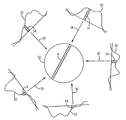
MRIで用いられる標準的な逆投影方法が、図3に図示されている。各取得信号投影プロファイル110がフーリエ変換され、次いで、変換されたプロファイル10内で、FOV12を通って、矢印16で示された投影経路に沿って各信号サンプル14を投影することによって、FOV12上に逆投影される。FOV12内の各信号サンプル16を投影する際に、本発明者らは、画像化される対象に関する先験的な情報を何ら有しておらず、FOV12内のNMR信号が均質であり、信号サンプル14は、投影経路が通る各画素に均等に分布していると仮定する。例えば、図3では、投影経路8がFOV12内のN個の画素を通るときの、1つの変換された信号投影プロファイル10における単一の信号サンプル14についての投影経路8が示されている。この信号サンプル14の信号値(P)は、これらのN個の画素の間で均等に分割される。
![]()
![]()
明らかに、FOV12の逆投影信号は均等であるという仮定は正しくない。しかし、当分野でよく知られているとおり、各信号プロファイル10に対してある一定の補正がなされ、十分な個数のプロファイルが、対応する個数の投影ビュー角で取得されるならば、この誤った仮定により生じる誤差が最小限になり、画像アーチファクトが抑制される。画像再構成の典型的なフィルタ補正逆投影法では、256×256画素の2D画像に対しては400個の投影が必要であり、256×256×256ボクセルの3D画像に対しては103,000個の投影が必要となる。
Clearly, the assumption that the
(発明の要約)
本発明は、取得された速度コード化MRデータから画像を再構成する方法であり、より詳細には、高度にアンダーサンプリングされたデータセットから速度コード化画像が再構成されることを可能にする高度に限定された逆投影方法である。本発明の高度に限定された逆投影方法を使用することによって、大幅に少ないビューで、且つアンダーサンプリングに起因する、臨床的に好ましくない画像アーチファクトを生成することなく速度コード化画像を取得することができる。これによって取得時間が短縮され、種々の速度コード化において画像を取得することが可能となる。
(Summary of the Invention)
The present invention is a method for reconstructing an image from acquired velocity-coded MR data, and more particularly allows a velocity-coded image to be reconstructed from a highly undersampled data set. This is a highly limited backprojection method. By using the highly limited backprojection method of the present invention, acquiring velocity coded images with significantly fewer views and without generating clinically undesirable image artifacts due to undersampling Can do. This shortens the acquisition time and makes it possible to acquire images in various speed encodings.
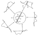
本発明の発見は、FOV12内の信号輪郭の先験的な情報が再構成プロセスで用いられるならば、大幅に少ない投影信号プロファイルを用いて良質の画像を生成できることである。合成画像がMRI走査の一部として取得され、合成画像は再構成されて、撮像される対象の先験的な知識を提供する。この合成画像を、高度にアンダーサンプリングされた速度コード化画像の再構成中に使用して、逆投影ビューの分配を重み付けする。例えば、図4を参照すると、FOV12の信号輪郭は、構造体18及び20を含むことが分かる。実際には、逆投影経路8がこれらの構造体を貫通するとき、信号サンプル14の各画素へのより正確な分配が、その画素位置で既知の信号輪郭の関数として分配に重み付けすることによって達成される。その結果、大多数の信号サンプル14が、図4の例において、構造体18及び20と交差する画素で分配される。N個の画素を有する逆投影経路8については、この高度に限定的な逆投影は、以下のように表すことができる。
![]()
合成画像は、走査中に取得されたデータから再構成され、フィールド・オブ・ビューで構造体を表す、他の取得画像データだけでなく画像を再構成するために用いられる合成画像を含んでもよい。数式(2)の分子は、合成画像において、対応する信号値を用いた各画素に重み付けし、分母は、全逆投影信号サンプルが、画像フレームに対する投影総和を反映し、合成画像の総和により乗算されないように、その値を正規化している。この正規化は、逆投影後に各画素で別個に行われることができるが、多くの臨床使用では、逆投影の前に投影Pを正規化する方がはるかに容易であることに留意すべきである。この場合、投影Pは、同じビュー角での合成画像を通した投影において対応する値PCで割ることによって正規化される。次に、正規化された投影P/PCは逆投影され、次に、結果として得た画像は合成画像を乗算される。
The discovery of the present invention is that, if a priori information of the signal contour in the
![]()
The composite image may include a composite image that is reconstructed from the data acquired during the scan and used to reconstruct the image as well as other acquired image data that represents the structure in the field of view. . The numerator of equation (2) weights each pixel using the corresponding signal value in the composite image, and the denominator is the total backprojection signal sample reflecting the projection sum for the image frame, multiplied by the sum of the composite image The value is normalized so that it is not. It should be noted that this normalization can be done separately for each pixel after backprojection, but for many clinical uses it is much easier to normalize projection P before backprojection. is there. In this case, the projection P is normalized by dividing by the corresponding value P C in a projection through the composite image at the same view angle. The normalized projection P / P C is then backprojected and the resulting image is then multiplied by the composite image.
3Dの実施態様が、ビュー角θとφで特徴付けられる単一の3D投影ビューに対して、図5に図示されている。この投影ビューは、軸16に沿って逆投影され、逆投影軸16に沿った距離rにおいてラドン平面21に広がる。投影信号値がフィルタ処理され、連続したラドン平面に、軸16に沿って均等に分配されるフィルタ補正逆投影の代わりに、投影信号値が、合成画像内の情報を用いて、ラドン平面22に分配される。図5の例における合成画像は、構造体18及び20を含む。重み付けされた信号輪郭値が、合成画像内の対応する位置x、y、zでの強度に基づいて、ラドン平面21内の画像位置x、y、zで置かれる。これは、対応する合成画像のボクセル値と信号プロファイル値との簡単な乗算である。次に、この積は、合成画像から形成された対応画像空間プロファイルからのプロファイル値でこの積を割ることによって正規化される。3D再構成に対する式は以下になる。
![]()
![]()
本発明の目的は、位相コントラスト磁気共鳴血管造影(PCMRA)画像を取得するのに必要な走査時間を短縮することである。本発明は、一連のこのような画像を取得する場合にPCMRA画像を取得するのに必要なビューの数を大幅に低減することを可能にする。 An object of the present invention is to reduce the scan time required to acquire a phase contrast magnetic resonance angiography (PCMRA) image. The present invention makes it possible to significantly reduce the number of views required to acquire a PCMRA image when acquiring a series of such images.
本発明の別の目的は、定量的測定能力を損なうことなく、速度画像又は流れ画像を取得するのに必要な走査時間を短縮することである。この高度に限定された逆投影方法を使用しての速度画像の再構成における1つの問題は、任意の画像画素における速度が、その画素位置におけるスピン運動の向きに応じて正又は負のいずれかの値を有する可能性があることである。結果として、投影ビューが取得されるとき、投影放射線は正の速度値及び負の速度値の両方を有する画素を通過し得る。実際に、あらゆる投影放射線に沿ったすべての速度を合計するとゼロになり得る可能性さえある。これによって提示され得る問題を回避するために、高度に限定された逆投影プロセス中にすべての信号を絶対値として扱い、次いで処理された信号の符号を再構成画像において復元することが本発明の教示である。 Another object of the present invention is to reduce the scan time required to acquire velocity or flow images without compromising quantitative measurement capabilities. One problem in reconstruction of velocity images using this highly limited backprojection method is that the velocity at any image pixel is either positive or negative depending on the direction of spin motion at that pixel location. It may have the value of As a result, when a projection view is acquired, projection radiation can pass through pixels having both positive and negative velocity values. In fact, the sum of all velocities along any projection radiation can even be zero. In order to avoid the problems that can be presented by this, it is possible to treat all signals as absolute values during the highly limited backprojection process and then restore the sign of the processed signal in the reconstructed image. It is teaching.
本発明のさらに別の目的は、高度に限定された逆投影方法を使用して複素差画像を生成することである。これは、高度に限定された逆投影方法を使用してI成分画像及びQ成分画像を別個に再構成すること、及び、次いで結果として生じるI成分画像及びQ成分画像を結合することによって達成される。 Yet another object of the present invention is to generate a complex difference image using a highly limited backprojection method. This is accomplished by reconstructing the I and Q component images separately using a highly limited backprojection method, and then combining the resulting I and Q component images. The
本発明における前記及び他の目的並びに利点は、以下の説明から明らかになろう。その説明では、本明細書の一部を形成し、且つ、例証として本発明の一つの好適な実施態様が示されている添付図面が参照される。しかし、そのような実施態様は必ずしも本発明の全範囲を表すものではなく、従って、本発明の範囲を解釈するためには、本明細書の特許請求の範囲を参照すべきである。 The above and other objects and advantages of the present invention will become apparent from the following description. In the description, reference is made to the accompanying drawings that form a part hereof, and in which is shown by way of illustration one preferred embodiment of the invention. Such embodiments, however, do not necessarily represent the full scope of the invention, and reference should be made therefore to the claims herein for interpreting the scope of the invention.
(好ましい実施態様の詳細な説明)
特に図1を参照すると、本発明の好ましい実施態様がMRIシステムに用いられる。MRIシステムは、ディスプレイ112及びキーボード114を有するワークステーション110を備える。ワークステーション110は、市販のオペレーティングシステムを走らせている市販のプログラマブルマシンであるプロセッサ116を備える。ワークステーション110は、スキャン指示をMRIシステムに入力できるようにするオペレータインタフェースを提供する。
Detailed Description of Preferred Embodiments
With particular reference to FIG. 1, the preferred embodiment of the present invention is used in an MRI system. The MRI system includes a
ワークステーション110は4つのサーバ、すなわちパルスシーケンスサーバ118、データ取得サーバ120、データ処理サーバ122、及びデータ記憶サーバ23に結合される。好ましい実施態様では、データ記憶サーバ23は、ワークステーションプロセッサ116及び関連するディスクドライブインタフェース回路によって実行される。残りの3つのサーバ118、120及び122は、単一のエンクロージャに搭載され、且つ64ビットバックプレーンバスを使用して相互接続された別個のプロセッサによって実行される。パルスシーケンスサーバ118は、市販のマイクロプロセッサ及び市販の4通信コントローラを用いる。データ取得サーバ120及びデータ処理サーバ122は両方とも、同じ市販のマイクロプロセッサを用い、データ処理サーバ122は、市販のパラレルベクトルプロセッサに基づいた1つ又は複数のアレイプロセッサをさらに備える。
The
ワークステーション110及びサーバ118、120及び122の各プロセッサは、シリアル通信ネットワークに接続される。このシリアルネットワークは、ワークステーション110からサーバ118、120及び122にダウンロードされたデータを伝達するとともに、サーバ間及びワークステーションとサーバの間で通信されるタグデータを伝達する。これに加えて、高速データリンクがデータ処理サーバ122とワークステーション110の間に設けられて、画像データをデータ記憶サーバ23に伝達する。
The
パルスシーケンスサーバ118は、ワークステーション110からダウンロードされたプログラム要素に応答して、勾配システム24及びRFシステム26を動作させるように機能する。指定されたスキャンを実行するために必要な勾配波形が生成されて勾配システム24に与えられ、勾配システム24はアセンブリ28内の勾配コイルを励起して、NMR信号の位置エンコーディングに使用される磁場勾配Gx、Gy、及びGzを生成する。勾配コイルアセンブリ28は、分極マグネット32及び全身RFコイル34を備えるマグネットアセンブリ30の一部を成す。
The
RF励起波形が、RFシステム26によりRFコイル34に与えられて、指定の磁気共鳴パルスシーケンスを実行する。RFコイル34により検出される応答性NMR信号はRFシステム26により受信され、パルスシーケンスサーバ118により生成されるコマンドの命令の下で増幅され、復調され、濾波され、デジタル化される。RFシステム26は、MRパルスシーケンスに使用される広範なRFパルスを生成するRFトランスミッタを備える。RFトランスミッタは、スキャン指示及びパルスシーケンスサーバ118からの命令に応答して、所望の周波数、位相、及びパルス振幅波形のRFパルスを生成する。生成されたRFパルスは、全身RFコイル34に与えることができ、1つ又は複数のローカルコイル又はコイルアレイに与えることができる。
An RF excitation waveform is provided by the
RFシステム26は、1つ又は複数のRFレシーバチャネルも備える。各RFレシーバチャネルは、接続されているコイルが受け取ったNMR信号を増幅するRF増幅器、及び受信したNMR信号のI及びQ直角位相成分を検出しデジタル化する直角位相検出器を備える。受信したNMR信号の大きさはこうして、I成分及びQ成分の二乗和の平方根によりいずれのサンプリングポイントでも求めることができ、
![]()
![]()
![]()
![]()
パルスシーケンスサーバ118は任意的に、生理的取得コントローラ36から患者データを受信する。コントローラ36は、電極からのECG信号又はベローズからの呼吸信号等、患者に接続されたいくつかの異なるセンサから信号を受信する。パルスシーケンスサーバ118は通常、このような信号を使用して、スキャンのパフォーマンスを患者の呼吸又は心拍に同期又は「ゲート」させる。
The
パルスシーケンスサーバ118は、患者及びマグネットシステムの状態に関連する各種センサから信号を受信するスキャンルームインタフェース回路38にも接続する。患者位置合わせシステム40がスキャン中に患者を所望の位置に移動させるコマンドを受信することもスキャンルームインタフェース回路38を通してである。
The
パルスシーケンスサーバ118が、スキャン中にMRIシステム要素のリアルタイム制御を行うことが明らかであるべきである。その結果、そのハードウェア要素がランタイムプログラムにより適時に実行されるプログラム命令で動作することが必要である。スキャン指示の指令構成要素は、ワークステーション110からオブジェクトの形でダウンロードされる。パルスシーケンスサーバ118は、これらオブジェクトを受け取るプログラムを含み、これらオブジェクトをランタイムプログラムに用いられるオブジェクトに変換する。
It should be apparent that the
RFシステム26により生成される、デジタル化されたNMR信号サンプルをデータ取得サーバ120が受け取る。データ取得サーバ120は、ワークステーション110からダウンロードされる指令構成要素に応答して動作し、リアルタイムNMRデータを受け取り、データがデータオーバーランにより失われないようにバッファストレージを提供する。スキャンによっては、データ取得サーバ120は、取得されたNMRデータをデータプロセッササーバ122に渡すにすぎない。しかし、取得されたNMRデータから導出された情報をスキャンのさらなるパフォーマンスの制御に必要とするスキャンでは、データ取得サーバ120は、このような情報を生成してパルスシーケンスサーバ118に伝達するようにプログラムされる。たとえば、プレスキャン中、NMRデータを取得し、これを使用してパルスシーケンスサーバ118により行われるパルスシーケンスを較正する。また、ナビゲータ信号をスキャン中に取得し、これを使用して、RFシステム又は勾配システムの動作パラメータを調整し、又はk空間がサンプリングされるビュー順序(view order)を制御することができる。また、データ取得サーバ120を用いて、MRAスキャン中に造影剤の到着を検出するために使用されるNMR信号を処理することができる。これら例のすべてにおいて、データ取得サーバ120はNMRデータを取得し、リアルタイムで処理して、スキャンの制御に使用される情報を生成する。
A
データ処理サーバ122は、NMRデータをデータ取得サーバ120から受け取り、ワークステーション110からダウンロードされた指令構成要素に従って処理する。このような処理には、たとえば、未処理のk空間NMRデータをフーリエ変換して2次元画像又は3次元画像を生成すること、再構成された画像にフィルタを適用すること、取得されたNMRデータの逆投影画像再構成を行うこと、機能MR画像を算出すること、動き又は流れの画像を算出すること等を含むことができる。
The data processing server 122 receives the NMR data from the
データ処理サーバ122により再構成される画像は再びワークステーション110に伝達されて記憶される。リアルタイム画像はデータベースメモリキャッシュ(図示せず)に記憶され、ここから画像を、マグネットアセンブリ30付近に配置され担当医師により使用されるオペレータディスプレイ112又はディスプレイ42に出力することができる。バッチモード画像又は選択されたリアルタイム画像は、ディスクストレージ44上のホストデータベースに記憶される。このような画像が再構成されストレージに転送されるとき、データ処理サーバ122はワークステーション110上のデータ記憶サーバ23に通知する。オペレータがワークステーション110を使用して、画像の保存、フィルムの生成、又はネットワークを介しての他の施設への画像の送信を行うことができる。
The image reconstructed by the data processing server 122 is transmitted again to the
図1のMRIシステムを用いる本発明の2つの実施態様を以下に記載する。第1の実施態様は、各画像画素におけるスピン速度の合計を定量的に示す速度画像を提供する。第2の実施態様は運動コード化勾配が血流を撮像するための位相コントラストメカニズムを提供するPCMRA画像を生成する。 Two embodiments of the present invention using the MRI system of FIG. 1 are described below. The first embodiment provides a velocity image that quantitatively shows the total spin velocity at each image pixel. The second embodiment generates a PCMRA image where the motion coding gradient provides a phase contrast mechanism for imaging blood flow.
特に図6を参照すると、パルスシーケンスサーバ118によって実施される例示的な運動コード化パルスシーケンスは、RF励起パルス250がGzスライス選択勾配252の存在下で印加されると共に、NMRエコー信号254がGx読取り勾配256及びGy読取り勾配257の存在下で取得される、グラジエント・リコールド・エコー・パルスシーケンスである。各読取り勾配256及び257は、RF励起パルス250によって生成される横磁化をそれぞれ脱位相化するディフェージング勾配258及び259によって先行される。読取り勾配256及び257は、エコー時間TEにおいてスピン磁化をリフェーズし、NMRエコー信号254におけるピークを生成する。
With particular reference to FIG. 6, an exemplary motion-encoded pulse sequence implemented by the
運動コード化勾配を使用せずに、このパルスシーケンスが繰り返されて2つの読取り勾配256及び257の大きさが、異なる値にステップされ、異なる投影角におけるNMRエコー信号254が取得される。これは図8に示されており、図8において、放射状の各線は各取得NMRエコー信号254によって達成されるkx−ky空間のサンプリングを表す。読取り勾配256及び257の振幅並びにそれらの対応するディフェージング勾配パルス258及び259は、各連続投影が角度θだけ回転するような値を通じてステップされる。
Without using a motion encoding gradient, this pulse sequence is repeated to step the magnitudes of the two
再び図6を参照すると、運動コード化MR画像を生成するために、各取得投影は、二極運動コード化勾配GMによって速度感知される。当分野でよく知られているとおり、速度コード化勾配GMは、サイズが等しく極性が反対の2つの勾配ローブ260及び262から成る。運動コード化勾配GMは、あらゆる方向に適用することができ、RF励起パルス250によって横磁化が生成された後で、且つNMRエコー信号254が取得される前に実行される。運動コード化勾配GMは、勾配GMの方向におけるスピン運動によって生成されるNMR信号を位相シフトさせ、この位相シフトの量はスピン運動の速度及び運動コード化勾配GMの第1のモーメントによって求められる。第1のモーメント(M1)は、勾配パルス260又は262の面積と、それらの間の時間間隔(t)との積に等しい。第1のモーメントM1は、大幅な位相シフトを提供するが、位相を高いスピン速度で一巡させるほどは大きくないように設定される。
Referring again to FIG. 6, in order to generate a motion encoding MR images, each acquired projection is the speed sensed by bipolar motion encoding gradient G M. As is well known in the art, the rate encoding gradient G M is size equal polarity consists opposite two
取得されたNMR信号254における位相シフトがスピン運動のみに起因することを確実にするために、通常各投影角で基準取得が行われる。好ましい実施態様では、第1のモーメントM1を有する運動コード化勾配GMによって取得される各運動コード化投影ビューに対して、負の第1のモーメント−M1を有する同じ運動コード化勾配GMを有する第2の投影ビューが取得される。これは、2つのGM勾配ローブ260及び262の極性を単純に反転することによって達成される。以下で説明するように、2つの結果として生じる信号が減算されると、スピン運動に起因しない位相シフトが速度決定から除去される。これらの望ましくない位相シフトを、以下バックグラウンド位相φBと称する。
In order to ensure that the phase shift in the acquired
上記で示したように、運動コード化勾配GMをあらゆる方向に適用することができる。好ましい実施態様では、運動コード化勾配GMは、勾配軸x、y及びzのそれぞれに沿って別個に適用され、それによって、合計スピン速度を示す画像を生成することができる。すなわち、z軸に沿った速度(vz)を示す画像が、図6に示されるGz勾配波形に加算された二極運動コード化勾配GMを用いて画像を取得することによって生成され、第2の速度画像VxがGx勾配波形に加算された運動コード化勾配GMを用いて取得され、第3の速度画像VyがGy勾配波形に加算された運動コード化勾配GMを用いて取得される。次いで、合計スピン速度を示す画像が、3つの速度画像における対応する画素値を結合することによって生成される。
![]()
![]()
運動コード化NMRエコー信号254を、k空間を完全にサンプリングするために各投影角(θ)で取得することが可能であるが、この実施態様では異なるインターリーブされた投影角で異なる運動コード化方向を取得する。これは図8に示されており、図8において、GMXは、x軸に沿って向けられた運動コード化勾配によって取得される投影を示し、GMYは、y軸に沿って向けられた運動コード化勾配によって取得される投影を示し、GMZは、z軸に沿って向けられた運動コード化勾配によって取得される投影を示す。合計でm=10の異なる投影が、3つの運動コード化方向のそれぞれに対して取得され、これらは3θの等角度をおいて離間される。各セットの取得された投影は、他の2つの方向に対して取得された投影によってインターリーブされ、その結果、画像フレームのすべての投影ビューが等角度θで離間され、k空間がほぼ均一にサンプリングされる。
A motion-coded
特に図9を参照すると、本発明の第1の好ましい実施態様において、上述の2Dパルスシーケンスが、対応する速度画像を再構成することができる一連の画像フレームを取得するのに用いられる。プロセスブロック200において示されるように、MRIシステムによってパルスシーケンスが実施され、1セット(m=10)の運動コード化NMR信号がx方向、y方向及びz方向のそれぞれに対して取得される。これらの投影ビューはk空間を可能な限り均一にサンプリングするように等間隔に離間され、異なる運動コード化方向が図8に示すようにインターリーブされる。画像フレームは、判断ブロック202において判断されるように所定数の画像フレーム(n)が取得されるまで、このようにして連続して且つ迅速に取得される。
With particular reference to FIG. 9, in the first preferred embodiment of the present invention, the 2D pulse sequence described above is used to obtain a series of image frames from which a corresponding velocity image can be reconstructed. As shown in
本発明のこの実施態様において、画像再構成は、走査のデータ取得段階が完了した後に実施される。この再構成プロセスはデータ処理サーバ122上で実施することができ、又は取得されたデータを別個のワークステーションに降ろしてMRIシステムを開放することができる。なお図9を参照すると、画像再構成プロセスにおける最初のステップは、プロセスブロック204において示されるように、各運動コード化方向に対する各±M1対の投影の複素減算を実施することである。図11も参照すると、これは、複素差
![]()
![]()
![]()
![]()
![]()
![]()
![]()
![]()
![]()
![]()
![]()
![]()
プロセスブロック201において示されるような次のステップは、各
![]()
![]()
![]()
![]()
![]()
![]()
![]()
![]()
![]()
![]()
プロセスブロック203において示されるように、次いで、|I|成分の合成画像319が形成される。これは、n個の画像フレーム315のすべてに関して対応する|I|画素値を共に加算することによって達成される。上記で示したように、n個の画像フレームに対して取得された投影ビューは互いにインターリーブされ、その結果、|I|合成画像319は絶対画像フレーム|I|315のいずれか1つよりも大幅に高い品質を有する。プロセスブロック205において示されるように、この手順は|Q|成分画像317について繰り返されて、|Q|合成画像321も形成される。これらの|I|合成画像319及び|Q|合成画像321は、位相情報、及びしたがって速さを保持しているため、まとめて合成位相画像とみなすことができる。
As shown in
プロセスブロック207において示されるように、次のステップは、n個の|I|成分画像フレーム315のそれぞれの|I|成分投影323のセットを生成することである。これは、(好ましい実施態様では)10個の投影が画像フレームを取得するのに使用される同じビュー角で生成される、標準的なラドン変換である。これは、商標「MATLAB」の下にMathworks,Incによって販売されている市販のソフトウェア内のラドン変換ツールを使用して為される。したがって、複素差の|I|成分のn個の画像フレーム315のそれぞれに対して、10個の投影ビューから成るセットが得られる。
As shown in
次いで、プロセスブロック209において示されるように、高度に限定された画像再構成プロセスが実施され、ラドン空間投影323のこれらのセットからn個の高品質の|I|成分画像325が生成される。この再構成方法は、図10を参照して以下でより詳細に説明するように、|I|成分合成画像319を使用する。
A highly confined image reconstruction process is then performed, as shown in
プロセスブロック211及び213において示されるように、次いで、上記ステップを|Q|成分に関して繰り返す。|Q|成分投影327のセットが、ラドン変換を使用して各画像フレーム317に関して算出され、次いでn個の|Q|成分画像フレーム329が、これより説明する高度に限定された逆投影方法を使用して再構成される。
As indicated in process blocks 211 and 213, the above steps are then repeated for the | Q | component. A set of | Q |
特に図10を参照すると、|I|成分画像フレーム325及び|Q|成分画像フレーム329のそれぞれは、それらのそれぞれの|I|投影データセット323及び|Q|投影データセット327、並びにそれらの対応する|I|合成画像319及び|Q|合成画像321を使用して再構成される。この高度に限定された逆投影再構成は数式(2)に関連して上述しており、図4に図示している。より詳細には、各|I|及び|Q|の成分投影Pが、プロセスブロック231において示されるように正規化される。各成分投影Pは、当該成分投影Pを、同じビュー角でのその対応する合成画像における投影PCで割ることによって正規化される。次いで、正規化された投影P/PCをFOVに逆投影する。これは標準的な逆投影であるが、フィルタ補正を伴わない。
Referring specifically to FIG. 10, each of the | I |
プロセスブロック233において示されるように、結果として生じる逆投影値が、再構成されている|I|画像フレーム又は|Q|画像フレームに加算され、判断ブロック235においてテストが行われ、現在の画像フレームのすべての投影ビューが逆投影されたか否かが判断される。すべての投影ビューが逆投影されていない場合、プロセスブロック237において示されるように、現在の|I|画像フレーム又は|Q|画像フレームにおける次の投影ビューが逆投影される。
As shown in
|I|画像フレーム又は|Q|画像フレームに関してすべての投影ビューが逆投影され合計されると、合計された画像フレームはその対応する|I|合成画像319又は|Q|合成画像321によって乗算される。これは、|I|画像フレーム又は|Q|画像フレームの画素値がそれぞれの|I|合成画像又は|Q|合成画像の対応する画素の値によって乗算される行列乗算である。2006年7月7日付で出願された、発明の名称が「高度に限定された画像再構成法(Highly Constrained Image Reconstruction Method)」の同時係属の米国特許出願第11/482,372号に記載されているように、この高度に限定された画像フレーム再構成を実施する他の方法を使用することができることが理解されるべきである。この特許文献は参照により本明細書に援用される。
When all projection views are backprojected and summed for a | I | image frame or | Q | image frame, the summed image frames are multiplied by their corresponding | I | composite image 319 or | Q |
|I|成分画像及び|Q|成分画像が各画像フレームに対して生成されたが、符号情報は失われており、各画像画素における|I|成分及び|Q|成分の符号(±)は分からない。この符号情報は、図9にプロセスブロック215において示されるように、I及びQの符号マップ333を生成することによって復元される。I及びQの符号マップは、アンダーサンプリングされた複素差画像309内のI成分及びQ成分の符号を検査することによって生成される。上記で示したように、これらはアンダーサンプリングに起因して品質に乏しい画像であるが、各画像画素において符号を示すには十分に良好である。
The | I | component image and | Q | component image are generated for each image frame, but the sign information is lost, and the sign (±) of the | I | component and | Q | I do not understand. This code information is recovered by generating an I and
プロセスブロック217において示されるように、次いで、この符号情報が|I|画像フレーム325及び|Q|画像フレーム329に対して復元される。これは、|I|成分画像フレーム325に、それらの対応するI符号マップ333を乗算すること、及び|Q|成分画像フレーム329に、それらの対応するQ符号マップ333を乗算することによって達成される。プロセスブロック219において示されるように、各画像フレームの符号を付されたI成分及びQ成分は、次いで、結合されて複素差画像
![]()
![]()
上記手順が各運動コード化方向に関して繰り返される。好ましい実施態様では、運動コード化が3つの勾配方向のすべてに用いられて、判断ブロック221において判断されるように、すべての方向に対して|CD|画像331及び
![]()
![]()
スピン速度を算出するために、+M1運動コード化画像と−M1運動コード化画像との間の位相差φvを算出しなければならない。これは図7に示されており、図7において、角φBはスピン運動以外の要因によって発生するバックグラウンド位相である。 In order to calculate the spin speed, the phase difference φ v between the + M 1 motion coded image and the −M 1 motion coded image must be calculated. This is illustrated in FIG. 7, where the angle φ B is the background phase generated by factors other than spin motion.
余弦の法則を使用して各画像画素の位相φvを計算する。
![]()
![]()
数式(6)が、対応するn個の|CD|画像331並びに2つの大きさ画像|+M1|350及び|−M1|画像352を使用して、n個の位相画像|φv|354のそれぞれを生成するのに使用される。しかしながら、位相画像354は符号情報を含まないので、符号情報を追加しなければならない。これを行うために、その画素のそれぞれにおいて位相差の符号+1又は−1を示す、アンダーサンプリングされた複素差画像
![]()
![]()
位相画像φv358が各運動コード化方向(好ましい実施態様ではx、y及びz)に対して算出されて、位相画像φv358から速度成分Vx、Vy及びVzが以下のように算出される。
![]()
次いで、これら3つの速度成分を数式(5)において上述のように結合し、n個の対応する合計速度画像フレームを生成する。
A phase image φ v 358 is calculated for each motion coding direction (x, y and z in the preferred embodiment), and velocity components V x , V y and V z from the phase image φ v 358 are as follows: Calculated.
![]()
These three velocity components are then combined as described above in equation (5) to produce n corresponding total velocity image frames.
好ましい実施態様において3つの勾配軸のすべてに沿った速度コード化が用いられるが、1つ又は2つの勾配軸のみに沿った速度コード化で十分な臨床状況が存在する。冠状動脈の測定には、たとえば流れに対して垂直なスライスにおける2D画像が取得され得る。1つのみの速度軸がコード化される。これによって取得ステップ及び画像再構成ステップの両方が短縮される。この場合、速度コード化勾配GMは、冠状動脈の方向に対応する傾斜角であり、GM勾配波形を、図6のパルスシーケンスの2つ又は3つの勾配軸Gx、Gy又はGzに沿って同時に生成することによって生成される。 In the preferred embodiment, velocity coding along all three gradient axes is used, but there are sufficient clinical situations with velocity coding along only one or two gradient axes. For measurement of coronary arteries, for example, 2D images in slices perpendicular to the flow can be acquired. Only one velocity axis is coded. This shortens both the acquisition step and the image reconstruction step. In this case, the velocity encoding gradient G M is the angle of inclination corresponding to the direction of the coronary artery, and the G M gradient waveform is represented by the two or three gradient axes G x , G y or G z of the pulse sequence of FIG. Are generated simultaneously.
本発明を使用して、一連の位相コントラストMRA画像を生成することもできる。このような応用態様では、2D又は3Dのパルスシーケンスを使用することができ、運動コード化が1つのみの軸に沿って適用される一連の画像が取得される。+M1及び−M1の運動コード化又は+M1及びM1=0の運動コード化のいずれかを用いて2つの画像が取得される。PCMRAでは、スピン速度を計算するのではなく、各再構成画像画素における位相φvが直接表示され、結果として、上述の手順を簡略化することができる。3D画像が取得される場合、図10及び数式(2)を参照して上述した高度に限定された逆投影が、上記で説明した三次元の数式(2a)によって図10に示されるように実施される。 The present invention can also be used to generate a series of phase contrast MRA images. In such applications, a 2D or 3D pulse sequence can be used, and a series of images is acquired where motion coding is applied along only one axis. Two images are acquired using either + M 1 and −M 1 motion coding or + M 1 and M 1 = 0 motion coding. In PCMRA, instead of calculating the spin speed, the phase φ v at each reconstructed image pixel is directly displayed, and as a result, the above procedure can be simplified. When a 3D image is acquired, the highly limited backprojection described above with reference to FIG. 10 and equation (2) is performed as shown in FIG. 10 by the three-dimensional equation (2a) described above. Is done.
上述の好ましい実施態様では、合成画像が走査全体の間に取得される投影から導出される情報を結合することによって形成される。これは再構成された画像フレームにおいて最大のSNRを提供するが、走査中に生じ得る速度の変化が一連のn個の速度画像において明確に示されない場合がある。したがって、動的な走査中に変化が生じる場合、合成画像の形成に使用される投影の数を、再構成されている現在の画像フレームの取得を取り囲むウィンドウに低減することができる。たとえば、現在の画像フレームと、現在の画像フレームの前後の2つの画像フレームにおいて取得される投影とから成るウィンドウを使用して合成画像を形成することができる。このウィンドウは処理されている各画像フレームに対して移動し、したがって、一連の各画像フレームに対して異なる合成画像が形成される。 In the preferred embodiment described above, the composite image is formed by combining information derived from projections acquired during the entire scan. This provides the maximum SNR in the reconstructed image frame, but the speed change that may occur during the scan may not be clearly shown in the series of n speed images. Thus, if changes occur during dynamic scanning, the number of projections used to form the composite image can be reduced to a window surrounding the acquisition of the current image frame being reconstructed. For example, a composite image can be formed using a window consisting of a current image frame and projections acquired in two image frames before and after the current image frame. This window moves for each image frame being processed, thus forming a different composite image for each series of image frames.
好ましい実施態様では、スピン運動以外の要因によって生じるバックグラウンド位相が、反対の極性の二極勾配によって生成される2つの信号、すなわち第1のモーメントM1を減算することによって検出される。同じ結果を達成する代替的な方法は、同じパルスシーケンスを用いるが、運動コード化は用いずに(すなわち、M1=0)第2の投影ビューを取得することである。結果として取得される2つの信号間の差は望ましくないバックグラウンド位相シフトを明らかにするが、結果として生じる速度画像のSNRが低減される。この実施態様は、単一の基準取得を、1つ、2つ又は3つの異なる運動方向コード化と共に使用することができるという時間的な利点を有する。したがって、好ましい実施態様において上述したような6回の取得の代わりに、各投影角で4回の取得のみが必要とされる。加えて、「4点平衡/ハマード(4-point balanced/hammard)」コード化方式を使用することもできる。 In a preferred embodiment, the background phase caused by factors other than spin motion is detected by subtracting the two signals generated by the opposite polarity bipolar gradient, namely the first moment M 1 . An alternative way to achieve the same result is to obtain a second projection view using the same pulse sequence but without motion coding (ie, M 1 = 0). The difference between the two resulting signals reveals an undesirable background phase shift, but the resulting velocity image SNR is reduced. This embodiment has the temporal advantage that a single reference acquisition can be used with one, two or three different motion direction encodings. Therefore, instead of 6 acquisitions as described above in the preferred embodiment, only 4 acquisitions at each projection angle are required. In addition, a “4-point balanced / hammard” encoding scheme may be used.
本発明の別の代替的な実施態様は、画像再構成プロセス中に符号情報を保持する異なる方法を用いる。上述のように絶対値(すなわち、速さ)画像を再構成して、それらを上述のように符号マップにおいて具現化される向き情報と結合するのではなく、別個の正の速さ画像と負の速さ画像とを再構成して結合し、速度画像を形成することができる。この場合、プロセスブロック201において絶対|I|成分画像フレーム及び絶対|Q|成分画像フレームを形成する代わりに、正のI成分画像フレーム及び正のQ成分画像フレーム、並びに負のI成分画像フレーム及び負のQ成分画像フレームを形成する。次いで、これらのすべてを上述のように別個に処理して、次いで高度に限定された逆投影ステップ後に結合する。
Another alternative embodiment of the present invention uses a different method of preserving sign information during the image reconstruction process. Rather than reconstructing absolute (ie, speed) images as described above and combining them with orientation information embodied in the code map as described above, separate positive speed images and negative images The speed image can be reconstructed and combined to form a speed image. In this case, instead of forming an absolute | I | component image frame and an absolute | Q | component image frame in
本発明は特に、スピン運動が位相差情報に反映され、正確な位相情報が、高度に限定された逆投影プロセス中に保持されなければならない運動コード化取得に適用可能である。位相差情報又は位相情報を保持しなければならない他の応用態様が存在する。本発明はこれらの状況にも同様に適用される。たとえば、運動コード化パルスシーケンスが、減算される2セットの投影ビューを取得して複素差データセット307を形成するのに使用されない応用態様が存在する。本発明がこの差データセットに上述のように用いられて、対応する複素差画像が再構成される。また、取得された複素投影ビューのセットが、高度に限定された再構成方法を使用して画像を再構成するのに使用され、位相情報が保持される応用態様が存在する。このような応用態様では、上述の手順が複素投影ビューのセットに用いられて、正確な位相情報を抽出することができる対応する複素画像が再構成される。
The present invention is particularly applicable to motion coding acquisition where spin motion is reflected in phase difference information and accurate phase information must be preserved during a highly limited backprojection process. There are other applications where phase difference information or phase information must be retained. The present invention applies to these situations as well. For example, there are applications where a motion-encoded pulse sequence is not used to obtain two sets of projection views to be subtracted to form a complex
Claims (17)
a)前記MRIシステムによって、第1の方向に沿って向けられる運動感知勾配を有するパルスシーケンスを使用して前記FOV内に位置決めされる前記対象の異なるビュー角で取得される投影ビューのセットを取得するステップであって、該投影ビューのセットが第1のアンダーサンプリング画像データセットを形成するステップと、
b)前記MRIシステムによって、前記第1の方向に沿って向けられる異なる運動感知勾配を有する前記パルスシーケンスを使用して前記FOV内に位置決めされる前記対象の投影ビューの第2のセットを取得するステップであって、該投影ビューの第2のセットが第2のアンダーサンプリング画像データセットを形成するステップと、
c)前記第1の方向に沿って運動感知される投影ビューの追加の第1及び第2のセットを取得するためにステップa)及びb)を複数回繰り返すステップであって、該投影ビューの追加のセット内の該投影ビューが、ステップa)及びb)において取得された前記投影ビューとインターリーブされるステップと、
d)前記第1のアンダーサンプリング画像データセットにおける対応する投影ビューのI成分及びQ成分と、前記第2のアンダーサンプリング画像データセットにおける対応する投影ビューのI成分及びQ成分と、の差分をとることによって、複数の複素差投影データセットを生成するステップと、
e)対応する複数の複素差投影データセットから複数のアンダーサンプリング複素差画像を再構成するステップと、
f)前記複数の複素差画像から前記I成分を選択することによって複数のI成分投影データセットを生成するステップと、
g)複数の前記I成分投影データセット内の投影データから、撮像される前記対象に関する先験的な情報を含むI成分合成画像を生成するステップと、
h)前記複数の複素差画像から前記Q成分を選択することによって複数のQ成分投影データセットを生成するステップと、
i)複数の前記Q成分投影データセット内の投影データから、撮像される前記対象に関する先験的な情報を含むQ成分合成画像を生成するステップと、
j)I成分投影データセットから、
j)i)前記I成分投影データセット内の前記投影ビューを前記FOVに逆投影すると共に、各I画像画素に逆投影された値を、前記I成分合成画像内の対応する位置における画素の正規化値によって重み付けすることと、
j)ii)各I画像画素の前記逆投影された値を合計することと
によって、I画像を再構成するステップと、
k)Q成分投影データセットから、
k)i)前記Q成分投影データセット内の前記投影ビューを前記FOVに逆投影すると共に、各Q画像画素に逆投影された値を、前記Q成分合成画像内の対応する位置における画素の正規化値によって重み付けすることと、
k)ii)各Q画像画素の前記逆投影された値を合計することと
によって、Q画像を再構成するステップと、
l)複素差画像を形成するために、前記再構成されたI画像と前記再構成されたQ画像とを結合するステップと
を含む、磁気共鳴イメージングシステムのFOV内に位置決めされる対象の画像を生成する方法。A method for generating an image of an object positioned within a field of view (FOV) of a magnetic resonance imaging system comprising:
a) obtaining a set of projection views acquired at different view angles of the object positioned in the FOV using a pulse sequence having a motion-sensing gradient directed along a first direction by the MRI system; The set of projection views forms a first undersampled image data set;
b) Acquire a second set of projection views of the object that are positioned in the FOV using the pulse sequence with different motion sensing gradients directed along the first direction by the MRI system. A second set of projection views forming a second undersampled image data set;
c) repeating steps a) and b) a plurality of times to obtain additional first and second sets of projection views that are motion-sensed along said first direction, comprising: Interleaving the projection views in an additional set with the projection views obtained in steps a) and b);
d) Taking the difference between the I and Q components of the corresponding projection view in the first undersampled image data set and the I and Q components of the corresponding projection view in the second undersampled image data set. by the steps of: generating a plurality of complex difference projection data sets,
e) reconstructing a plurality of undersampled complex difference images from a corresponding plurality of complex difference projection data sets;
f) generating a plurality of I component projection data sets by selecting the I component from the plurality of complex difference images;
g) generating an I component composite image including a priori information about the object to be imaged from projection data in the plurality of I component projection data sets;
h) generating a plurality of Q component projection data sets by selecting the Q component from the plurality of complex difference images;
i) generating a Q component composite image including a priori information about the object to be imaged from projection data in a plurality of the Q component projection data sets;
j) From the I component projection data set:
j) i) Backprojecting the projection view in the I component projection data set to the FOV and the backprojected value to each I image pixel to the normal of the pixel at the corresponding position in the I component composite image Weighting by the digitization value;
j) ii) reconstructing an I image by summing the backprojected values of each I image pixel;
k) From the Q component projection data set:
k) i) Back-projecting the projection view in the Q-component projection data set to the FOV and back-projecting the value projected to each Q image pixel to the normal of the pixel at the corresponding position in the Q-component composite image Weighting by the digitization value;
k) ii) reconstructing a Q image by summing the backprojected values of each Q image pixel;
l) combining the reconstructed I image and the reconstructed Q image to form an image of the object to be positioned in the FOV of the magnetic resonance imaging system, to form a complex difference image How to generate.

n)第3の複素差画像を生成するために、ステップa)、b)及びc)において第3の方向に沿って向けられる運動コード化勾配を使用してステップa)〜l)を繰り返すステップと、
o)前記3つの複素画像を使用して速度画像を生成するステップと
を含む、請求項1記載の方法。m) Repeat steps a) -l) using the motion coding gradient directed along the second direction in steps a), b) and c) to generate a second complex difference image. When,
n) Repeat steps a) -l) using the motion coding gradient directed along the third direction in steps a), b) and c) to generate a third complex difference image. When,
and o) generating a velocity image using the three complex images.
a)前記MRIシステムによって、パルスシーケンスを使用して前記FOV内に位置決めされる前記対象の投影ビューのセットを取得するステップであって、該投影ビューのセットが第1のアンダーサンプリング画像データセットを形成するステップと、
b)前記MRIシステムによって、前記パルスシーケンスを使用して前記FOV内に位置決めされる前記対象の投影ビューの第2のセットを取得するステップであって、該投影ビューの第2のセットが第2のアンダーサンプリング画像データセットを形成するステップと、
c)投影ビューの追加の第1及び第2のセットを取得するためにステップa)及びb)を複数回繰り返すステップであって、該投影ビューの追加のセット内の該投影ビューがインターリーブされるステップと、
d)前記第1のアンダーサンプリング画像データセットにおける対応する投影ビューのI成分及びQ成分と、前記第2のアンダーサンプリング画像データセットにおける対応する投影ビューのI成分及びQ成分と、の差分をとることによって、複数の複素差投影データセットを生成するステップと、
e)対応する複数の複素差投影データセットから複数のアンダーサンプリング複素差画像を再構成するステップと、
f)前記複数の複素差画像から複数のI成分投影データセットを生成するステップと、
g)複数の前記I成分投影データセット内の投影データからI成分合成画像を生成するステップと、
h)前記複数の複素差画像から複数のQ成分投影データセットを生成するステップと、
i)複数の前記Q成分投影データセット内の投影データからQ成分合成画像を生成するステップと、
j)I成分投影データセットから、
j)i)前記I成分投影データセット内の前記投影ビューを前記FOVに逆投影すると共に、各I画像画素に逆投影された値を、前記I成分合成画像内の対応する画素の正規化値によって重み付けすることと、
j)ii)各I画像画素の前記逆投影された値を合計することとによって、I画像を再構成するステップと、
k)Q成分投影データセットから、
k)i)前記Q成分投影データセット内の前記投影ビューを前記FOVに逆投影すると共に、各Q画像画素に逆投影された値を、前記Q成分合成画像内の対応する画素の正規化値によって重み付けすることと、
k)ii)各Q画像画素の前記逆投影された値を合計することとによって、Q画像を再構成するステップと、
l)複素差画像を形成するために、前記再構成されたI画像と前記再構成されたQ画像とを結合するステップと
を含む、磁気共鳴イメージングシステムのFOV内に位置決めされる対象の画像を生成する方法。A method for generating an image of an object positioned within a field of view (FOV) of a magnetic resonance imaging system comprising:
a) obtaining, by the MRI system, a set of projection views of the object to be positioned in the FOV using a pulse sequence, the set of projection views comprising a first undersampled image data set; Forming step;
b) obtaining, by the MRI system, a second set of projection views of the object that are positioned in the FOV using the pulse sequence, the second set of projection views being a second Forming an undersampled image data set of:
c) repeating steps a) and b) multiple times to obtain an additional first and second set of projection views, wherein the projection views in the additional set of projection views are interleaved. Steps,
d) Taking the difference between the I and Q components of the corresponding projection view in the first undersampled image data set and the I and Q components of the corresponding projection view in the second undersampled image data set. by the steps of: generating a plurality of complex difference projection data sets,
e) reconstructing a plurality of undersampled complex difference images from a corresponding plurality of complex difference projection data sets;
f) generating a plurality of I component projection data sets from the plurality of complex difference images;
g) generating an I component composite image from projection data in the plurality of I component projection data sets;
h) generating a plurality of Q component projection data sets from the plurality of complex difference images;
i) generating a Q component composite image from projection data in the plurality of Q component projection data sets;
j) From the I component projection data set:
j) i) Backprojecting the projection view in the I component projection data set to the FOV and the backprojected value to each I image pixel is the normalized value of the corresponding pixel in the I component composite image Weighting by,
j) ii) reconstructing an I image by summing the backprojected values of each I image pixel;
k) From the Q component projection data set:
k) i) backprojecting the projection view in the Q component projection data set to the FOV and backprojecting the value to each Q image pixel to the normalized value of the corresponding pixel in the Q component composite image Weighting by,
k) ii) reconstructing a Q image by summing the backprojected values of each Q image pixel;
l) combining the reconstructed I image and the reconstructed Q image to form an image of the object to be positioned in the FOV of the magnetic resonance imaging system, to form a complex difference image How to generate.
前記位相画像に前記符号を乗算することと
を含む、請求項13記載の方法。 Determining a code map having information of codes of the I component and the Q component from an undersampling complex difference image;
14. The method of claim 13, comprising multiplying the phase image by the code .
a)前記MRIシステムによって、パルスシーケンスを使用して前記FOV内に位置決めされる前記対象の異なるビュー角で取得される投影ビューのセットを取得するステップであって、該投影ビューのセットが第1のアンダーサンプリング画像データセットを形成するステップと、
b)投影ビューの追加の第1のセットを取得するためにステップa)を複数回繰り返すステップであって、該投影ビューの追加のセット内の該投影ビューが、ステップa)において取得された前記投影ビューとインターリーブされるステップと、
c)対応する複数の投影データセットから複数のアンダーサンプリング画像を再構成するステップと、
d)前記複数のアンダーサンプリング画像からI成分を選択することによって複数のI成分投影データセットを生成するステップと、
e)複数の前記I成分投影データセット内の投影データから、撮像される前記対象に関する先験的な情報を含むI成分合成画像を生成するステップと、
f)前記複数のアンダーサンプリング画像からQ成分を選択することによって複数のQ成分投影データセットを生成するステップと、
g)複数の前記Q成分投影データセット内の投影データから、撮像される前記対象に関する先験的な情報を含むQ成分合成画像を生成するステップと、
h)I成分投影データセットから、
h)i)前記I成分投影データセット内の前記投影ビューを前記FOVに逆投影すると共に、各I画像画素に逆投影された値を、前記I成分合成画像内の対応する位置における画素の正規化値によって重み付けすることと、
h)ii)各I画像画素の前記逆投影された値を合計することと
によって、I画像を再構成するステップと、
i)Q成分投影データセットから、
i)i)前記Q成分投影データセット内の前記投影ビューを前記FOVに逆投影すると共に、各Q画像画素に逆投影された値を、前記Q成分合成画像内の対応する位置における画素の正規化値によって重み付けすることと、
i)ii)各Q画像画素の前記逆投影された値を合計することと
によって、Q画像を再構成するステップと、
j)複素画像を形成するために、前記再構成されたI画像と前記再構成されたQ画像とを結合するステップと、
k)前記複素画像から位相画像を生成するステップと、
l)アンダーサンプリング画像から前記I成分及び前記Q成分の符号の情報を有する符号マップを決定すると共に、前記位相画像に前記符号を乗算するステップと
を含む、磁気共鳴イメージングシステムのFOV内に位置決めされる対象の画像を生成する方法。A method for generating an image of an object positioned within a field of view (FOV) of a magnetic resonance imaging system comprising:
a) obtaining by the MRI system a set of projection views acquired at different view angles of the object positioned in the FOV using a pulse sequence, the set of projection views being a first Forming an undersampled image data set of:
b) repeating step a) multiple times to obtain an additional first set of projection views, wherein the projection views in the additional set of projection views were acquired in step a) Steps interleaved with the projected view;
c) reconstructing a plurality of undersampled images from a corresponding plurality of projection data sets;
d) generating a plurality of I component projection data sets by selecting an I component from the plurality of undersampled images;
e) generating an I component composite image including a priori information about the object to be imaged from projection data in the plurality of I component projection data sets;
f) generating a plurality of Q component projection data sets by selecting a Q component from the plurality of undersampled images;
g) generating a Q component composite image including a priori information about the object to be imaged from projection data in a plurality of Q component projection data sets;
h) From the I component projection data set:
h) i) Backprojecting the projection view in the I component projection data set to the FOV and the backprojected value to each I image pixel to the normal of the pixel at the corresponding position in the I component composite image Weighting by the digitization value;
h) ii) reconstructing an I image by summing the backprojected values of each I image pixel;
i) From the Q component projection data set:
i) i) Back-projecting the projection view in the Q-component projection data set to the FOV, and using the back-projected value to each Q image pixel, the pixel normalization at the corresponding position in the Q-component composite image Weighting by the digitization value;
i) ii) reconstructing a Q image by summing the backprojected values of each Q image pixel;
j) combining the reconstructed I image and the reconstructed Q image to form a complex image;
k) generating a phase image from the complex image;
and determines a symbol map from l) undersampled image having information code of the I component and the Q component, and a step of multiplying said code to said phase image is positioned in the FOV of the magnetic resonance imaging system A method of generating an image of a target.
Applications Claiming Priority (5)
| Application Number | Priority Date | Filing Date | Title |
|---|---|---|---|
| US71944505P | 2005-09-22 | 2005-09-22 | |
| US60/719,445 | 2005-09-22 | ||
| US78078806P | 2006-03-09 | 2006-03-09 | |
| US60/780,788 | 2006-03-09 | ||
| PCT/US2006/035178 WO2007037951A2 (en) | 2005-09-22 | 2006-09-08 | Reconstruction of motion encoded mr images involving a highly constrained backprojection |
Publications (3)
| Publication Number | Publication Date |
|---|---|
| JP2009508635A JP2009508635A (en) | 2009-03-05 |
| JP2009508635A5 JP2009508635A5 (en) | 2011-06-02 |
| JP5113061B2 true JP5113061B2 (en) | 2013-01-09 |
Family
ID=37808231
Family Applications (1)
| Application Number | Title | Priority Date | Filing Date |
|---|---|---|---|
| JP2008532265A Active JP5113061B2 (en) | 2005-09-22 | 2006-09-08 | Highly limited reconstruction of motion-coded MR images |
Country Status (4)
| Country | Link |
|---|---|
| US (1) | US7711166B2 (en) |
| EP (1) | EP1927010B1 (en) |
| JP (1) | JP5113061B2 (en) |
| WO (1) | WO2007037951A2 (en) |
Cited By (1)
| Publication number | Priority date | Publication date | Assignee | Title |
|---|---|---|---|---|
| US9771699B2 (en) | 2012-10-23 | 2017-09-26 | Eextreme Global Limited | Retention device |
Families Citing this family (28)
| Publication number | Priority date | Publication date | Assignee | Title |
|---|---|---|---|---|
| US7647088B2 (en) * | 2005-09-22 | 2010-01-12 | Wisconsin Alumni Research Foundation | Reconstruction method for images of the beating heart |
| US7408347B2 (en) * | 2005-09-22 | 2008-08-05 | Wisconsin Alumni Research Foundation | Highly constrained magnetic resonance spectroscopy image reconstruction method |
| JP5105848B2 (en) * | 2006-02-06 | 2012-12-26 | 株式会社東芝 | Magnetic resonance imaging apparatus and imaging condition setting method in magnetic resonance imaging apparatus |
| US7558414B2 (en) * | 2006-09-11 | 2009-07-07 | Case Western Reserve University | Iterative image reconstruction |
| US7991452B2 (en) | 2007-01-02 | 2011-08-02 | Wisconsin Alumni Research Foundation | Contrast enhanced MRA with highly constrained backprojection reconstruction using phase contrast composite image |
| ATE542196T1 (en) | 2007-02-19 | 2012-02-15 | Wisconsin Alumni Res Found | METHOD FOR LOCALIZED AND HIGHLY LIMITED IMAGE RECONSTRUCTION |
| EP1959397B1 (en) * | 2007-02-19 | 2019-08-07 | Wisconsin Alumni Research Foundation | Iterative HYPR medical image reconstruction |
| US8825138B2 (en) * | 2007-09-17 | 2014-09-02 | Wisconsin Alumni Research Foundation | Method for reducing motion artifacts in highly constrained medical images |
| US8111810B2 (en) * | 2007-11-13 | 2012-02-07 | Wisconsin Alumni Research Foundation | Method for producing highly constrained ultrasound images |
| ATE528733T1 (en) * | 2007-12-20 | 2011-10-15 | Wisconsin Alumni Res Found | METHOD FOR DYNAMIC CONSTRAINTED IMAGE RECONSTRUCTION WITH PREVIOUS IMAGE |
| EP2232446B1 (en) | 2007-12-20 | 2013-04-17 | Wisconsin Alumni Research Foundation | Method for prior image constrained image reconstruction |
| WO2009091824A1 (en) * | 2008-01-14 | 2009-07-23 | Wisconsin Alumni Research Foundation | Method for prior image constrained progressive image reconstruction |
| US9858716B2 (en) * | 2008-02-28 | 2018-01-02 | International Business Machines Corporation | Fast three-dimensional visualization of object volumes without image reconstruction by direct display of acquired sensor data |
| US8143891B2 (en) * | 2008-08-29 | 2012-03-27 | Siemens Aktiengesellschaft | System for image acquisition with fast magnetic resonance gradient echo sequences |
| US8148984B2 (en) * | 2008-10-03 | 2012-04-03 | Wisconsin Alumni Research Foundation | Method for magnitude constrained phase contrast magnetic resonance imaging |
| EP2349008B1 (en) * | 2008-11-26 | 2015-02-25 | Wisconsin Alumni Research Foundation | Method for prior image constrained image reconstruction in cardiac cone beam computed tomography |
| US8111893B2 (en) * | 2009-06-09 | 2012-02-07 | Wisconsin Alumni Research Foundation | Method for dynamic prior image constrained image reconstruction |
| US8274284B2 (en) * | 2009-10-06 | 2012-09-25 | Northshore University Healthsystem | Parallel-accelerated complex subtraction MRI |
| US8761478B2 (en) * | 2009-12-15 | 2014-06-24 | General Electric Company | System and method for tomographic data acquisition and image reconstruction |
| US8204172B1 (en) * | 2010-03-17 | 2012-06-19 | General Electric Company | System and method of prior image constrained image reconstruction using short scan image data and objective function minimization |
| US8483463B2 (en) | 2010-05-19 | 2013-07-09 | Wisconsin Alumni Research Foundation | Method for radiation dose reduction using prior image constrained image reconstruction |
| EP2656094A2 (en) | 2010-12-22 | 2013-10-30 | Koninklijke Philips N.V. | Rapid parallel reconstruction for arbitrary k-space trajectories |
| US8781243B2 (en) | 2011-01-07 | 2014-07-15 | Wisconsin Alumni Research Foundation | Method for constrained reconstruction of high signal-to-noise ratio images |
| DE102011077197B4 (en) * | 2011-06-08 | 2013-05-16 | Siemens Aktiengesellschaft | Distortion correction in magnetic resonance imaging |
| KR101351583B1 (en) * | 2012-10-10 | 2014-01-16 | 한국과학기술원 | Medical image imaging method, medical diagnostic apparatus thereof, and recording device thereof |
| US9208588B2 (en) | 2013-09-25 | 2015-12-08 | Wisconsin Alumni Research Foundation | Fast statistical imaging reconstruction via denoised ordered-subset statistically-penalized algebraic reconstruction technique |
| US20160135775A1 (en) * | 2014-11-17 | 2016-05-19 | Wisconsin Alumni Research Foundation | System And Method For Time-Resolved, Three-Dimensional Angiography With Physiological Information |
| US10267883B2 (en) * | 2015-12-11 | 2019-04-23 | Siemens Healthcare Gmbh | System and method for motion resolved MRI |
Family Cites Families (16)
| Publication number | Priority date | Publication date | Assignee | Title |
|---|---|---|---|---|
| US5603322A (en) * | 1993-01-19 | 1997-02-18 | Mcw Research Foundation | Time course MRI imaging of brain functions |
| EP0627633A1 (en) | 1993-05-18 | 1994-12-07 | Koninklijke Philips Electronics N.V. | Method and apparatus for magnetic resonance imaging |
| DE4319539A1 (en) * | 1993-06-12 | 1994-12-15 | Philips Patentverwaltung | Method for generating an MR image sequence and arrangement for carrying out the method |
| DE4436688A1 (en) * | 1994-10-13 | 1996-04-25 | Siemens Ag | Spiral computer tomograph for human body investigation |
| DE19647537A1 (en) * | 1996-11-16 | 1998-05-20 | Philips Patentverwaltung | MR method for reducing movement artifacts and arrangement for carrying out the method |
| WO1999030179A2 (en) * | 1997-12-12 | 1999-06-17 | Wisconsin Alumni Research Foundation | Rapid acquisition magnetic resonance imaging using radial projections |
| US6487435B2 (en) * | 1998-04-10 | 2002-11-26 | Wisconsin Alumni Research Foundation | Magnetic resonance angiography using undersampled 3D projection imaging |
| US6188922B1 (en) * | 1999-01-08 | 2001-02-13 | Wisconsin Alumni Research Foundation | Phase contrast imaging using interleaved projection data |
| US6490472B1 (en) * | 1999-09-03 | 2002-12-03 | The Mcw Research Foundation, Inc. | MRI system and method for producing an index indicative of alzheimer's disease |
| JPWO2002067779A1 (en) * | 2001-02-28 | 2004-06-24 | 三菱重工業株式会社 | Multi-source X-ray CT system |
| DE10119660B4 (en) * | 2001-04-20 | 2006-01-05 | Siemens Ag | Method for the rapid acquisition of a magnetic resonance image |
| JP3878176B2 (en) * | 2001-11-12 | 2007-02-07 | ウイスコンシン アラムナイ リサーチ フオンデーシヨン | Three-dimensional phase contrast magnetic resonance imaging using interleaved projection-reconstruction data |
| GB0321895D0 (en) | 2003-09-18 | 2003-10-22 | Inst Of Cancer Res The | A method and apparatus for image reconstruction |
| US7403005B2 (en) | 2004-01-14 | 2008-07-22 | Koninklijke Philips Electronics, N.V. | Regularized variable density SENSE |
| DE602006010388D1 (en) * | 2005-07-08 | 2009-12-24 | Wisconsin Alumni Res Found | Image reconstruction under constraints |
| ATE492006T1 (en) * | 2005-07-08 | 2011-01-15 | Wisconsin Alumni Res Found | BACK PROJECTION RECONSTRUCTION METHOD FOR CT IMAGING |
-
2006
- 2006-09-08 WO PCT/US2006/035178 patent/WO2007037951A2/en active Application Filing
- 2006-09-08 JP JP2008532265A patent/JP5113061B2/en active Active
- 2006-09-08 EP EP06814390.8A patent/EP1927010B1/en active Active
- 2006-09-28 US US11/518,036 patent/US7711166B2/en active Active
Cited By (1)
| Publication number | Priority date | Publication date | Assignee | Title |
|---|---|---|---|---|
| US9771699B2 (en) | 2012-10-23 | 2017-09-26 | Eextreme Global Limited | Retention device |
Also Published As
| Publication number | Publication date |
|---|---|
| JP2009508635A (en) | 2009-03-05 |
| US20070156044A1 (en) | 2007-07-05 |
| EP1927010A2 (en) | 2008-06-04 |
| WO2007037951A3 (en) | 2007-05-18 |
| US7711166B2 (en) | 2010-05-04 |
| EP1927010B1 (en) | 2016-01-06 |
| WO2007037951A2 (en) | 2007-04-05 |
Similar Documents
| Publication | Publication Date | Title |
|---|---|---|
| JP5113061B2 (en) | Highly limited reconstruction of motion-coded MR images | |
| JP5167125B2 (en) | Limited backprojection reconstruction of undersampled MRI | |
| JP5123191B2 (en) | Diffusion tensor imaging using highly constrained image reconstruction methods | |
| JP5123192B2 (en) | Image acquisition and reconstruction methods for functional magnetic resonance imaging | |
| JP5113060B2 (en) | Reconstruction of beating heart image | |
| JP5737725B2 (en) | Localization and highly limited image reconstruction methods | |
| JP5325795B2 (en) | Contrast-enhanced MRA using highly constrained backprojection reconstruction method using phase difference composite image | |
| US7408347B2 (en) | Highly constrained magnetic resonance spectroscopy image reconstruction method | |
| JP2009508654A (en) | Highly limited magnetic resonance spectroscopy image reconstruction method |
Legal Events
| Date | Code | Title | Description |
|---|---|---|---|
| A621 | Written request for application examination |
Free format text: JAPANESE INTERMEDIATE CODE: A621 Effective date: 20090831 |
|
| A521 | Request for written amendment filed |
Free format text: JAPANESE INTERMEDIATE CODE: A523 Effective date: 20110414 |
|
| A131 | Notification of reasons for refusal |
Free format text: JAPANESE INTERMEDIATE CODE: A131 Effective date: 20120501 |
|
| A521 | Request for written amendment filed |
Free format text: JAPANESE INTERMEDIATE CODE: A523 Effective date: 20120730 |
|
| TRDD | Decision of grant or rejection written | ||
| A01 | Written decision to grant a patent or to grant a registration (utility model) |
Free format text: JAPANESE INTERMEDIATE CODE: A01 Effective date: 20121002 |
|
| A01 | Written decision to grant a patent or to grant a registration (utility model) |
Free format text: JAPANESE INTERMEDIATE CODE: A01 |
|
| A61 | First payment of annual fees (during grant procedure) |
Free format text: JAPANESE INTERMEDIATE CODE: A61 Effective date: 20121011 |
|
| FPAY | Renewal fee payment (event date is renewal date of database) |
Free format text: PAYMENT UNTIL: 20151019 Year of fee payment: 3 |
|
| R150 | Certificate of patent or registration of utility model |
Ref document number: 5113061 Country of ref document: JP Free format text: JAPANESE INTERMEDIATE CODE: R150 Free format text: JAPANESE INTERMEDIATE CODE: R150 |
|
| R250 | Receipt of annual fees |
Free format text: JAPANESE INTERMEDIATE CODE: R250 |
|
| R250 | Receipt of annual fees |
Free format text: JAPANESE INTERMEDIATE CODE: R250 |
|
| R250 | Receipt of annual fees |
Free format text: JAPANESE INTERMEDIATE CODE: R250 |
|
| R250 | Receipt of annual fees |
Free format text: JAPANESE INTERMEDIATE CODE: R250 |
|
| R250 | Receipt of annual fees |
Free format text: JAPANESE INTERMEDIATE CODE: R250 |
|
| R250 | Receipt of annual fees |
Free format text: JAPANESE INTERMEDIATE CODE: R250 |
|
| R250 | Receipt of annual fees |
Free format text: JAPANESE INTERMEDIATE CODE: R250 |
|
| R250 | Receipt of annual fees |
Free format text: JAPANESE INTERMEDIATE CODE: R250 |
|
| R250 | Receipt of annual fees |
Free format text: JAPANESE INTERMEDIATE CODE: R250 |