JP5111953B2 - Insufflation gas circulation device and insufflation gas circulation system provided with the same - Google Patents
Insufflation gas circulation device and insufflation gas circulation system provided with the same Download PDFInfo
- Publication number
- JP5111953B2 JP5111953B2 JP2007164891A JP2007164891A JP5111953B2 JP 5111953 B2 JP5111953 B2 JP 5111953B2 JP 2007164891 A JP2007164891 A JP 2007164891A JP 2007164891 A JP2007164891 A JP 2007164891A JP 5111953 B2 JP5111953 B2 JP 5111953B2
- Authority
- JP
- Japan
- Prior art keywords
- gas
- side tube
- trocar
- discharge side
- patient
- Prior art date
- Legal status (The legal status is an assumption and is not a legal conclusion. Google has not performed a legal analysis and makes no representation as to the accuracy of the status listed.)
- Expired - Fee Related
Links
Images


Landscapes
- Surgical Instruments (AREA)
Description
本発明は、内視鏡手術における手術中の視野を良好に確保するための技術に関するものである。 The present invention relates to a technique for ensuring a good visual field during surgery in endoscopic surgery.
従来から、患者の腹腔内にガスを供給して当該腹腔内を所定の圧力とし、腹壁を膨張させることにより、腹腔内に挿入された内視鏡の視野を良好に確保する技術、いわゆる気腹法が知られている。 Conventionally, a technique for ensuring a good field of view of an endoscope inserted into the abdominal cavity by supplying gas into the abdominal cavity of the patient to make the abdominal cavity a predetermined pressure and inflating the abdominal wall, so-called pneumoperitoneum The law is known.
この気腹法では、図11に示すように、患者の腹壁J1に穿刺された筒状のトロッカー101に気腹装置102が接続され、この気腹装置102から導出されるCO2ガスを前記トロッカー101を通して患者の腹腔J2内に排出するのが一般である。この気腹法により、腹腔J2内に挿入された内視鏡103の視野を良好に確保することができる。
In this insufflation method, as shown in FIG. 11, an
また、内視鏡手術においては、前記トロッカー101だけでなく、電気メス、レーザー又は超音波凝固切開装置等を含む器具104を腹腔J2内に挿入するためのトロッカー105及びトロッカー106も挿入される。つまり、内視鏡手術では、内視鏡103や器具104等を挿入するために複数のトロッカーが穿刺されるのが一般である。これらトロッカー105、106を通して挿入された器具104によって患者の組織J3の切開等が行われる。
In endoscopic surgery, not only the
しかしながら、前記器具104により組織J3の切開等を行う際には、当該組織J3の発熱や組織J3の微細片の拡散等によって腹腔J2内に煙やミストJ4が発生して、内視鏡103の視野が悪化する場合がある。
However, when an incision or the like of the tissue J3 is performed by the
このような問題を解消するための装置として、例えば特許文献1には、煙クリーニング装置(Smoke cleaning device)107が開示されている。この煙クリーニング装置107は、前記各トロッカー105、106に対しそれぞれチューブ108及びチューブ109を介して接続されている。
As an apparatus for solving such a problem, for example, Patent Document 1 discloses a
そして、煙クリーニング装置107は、前記チューブ108を通して腹腔J2内の気体を吸引するとともに、この気体を煙クリーニング装置107に設けられたフィルターに通した上で前記チューブ109を通して腹腔J2内に戻すことにより、前記煙やミストJ4を取り除くようになっている。
しかしながら、前記特許文献1の技術では、腹腔J2内のCO2ガスを一旦患者の体外に導くので、この間にCO2ガスの温度が室温の影響を受けて腹腔J2内の温度よりも低下する場合がある。 However, in the technique of Patent Document 1, CO2 gas in the abdominal cavity J2 is once guided outside the patient's body, and during this time, the temperature of the CO2 gas may be lower than the temperature in the abdominal cavity J2 due to the influence of room temperature. .
そして、特許文献1の技術では、体外に導いたCO2ガスをそのまま患者の腹腔J2内に戻すようにしているので、当該CO2ガスに温度低下が生じている場合には患者の体温等に影響を及ぼすおそれがあり、術中の患者の状態管理等に余分な労力を要することがある。 In the technique of Patent Document 1, since the CO2 gas guided outside the body is returned as it is into the abdominal cavity J2 of the patient, when the temperature of the CO2 gas is lowered, the body temperature of the patient is affected. In some cases, extra effort may be required to manage the patient's condition during surgery.
また、上記のようにCO2ガスに温度低下が生じると、前記チューブ109内に結露が生じ、この結露による水滴がチューブ109内のCO2ガスの流れに応じて腹腔J2内に導入されるおそれもある。
Further, when the temperature of the CO2 gas is lowered as described above, condensation occurs in the
本発明は、上記課題に鑑みてなされたものであり、結露の発生を抑制しながら術中における患者の状態管理の労力増加を防止することができる気腹ガス循環装置及びこれを備えた気腹ガス循環システムを提供することを目的としている。 The present invention has been made in view of the above problems, and an insufflation gas circulation device capable of preventing an increase in labor for managing the condition of a patient during an operation while suppressing the occurrence of dew condensation, and an insufflation gas provided with the same It aims to provide a circulation system.
上記課題を解決するために、本発明は、患者の腹壁に穿刺可能な一対のトロッカー同士を連結可能に構成され、当該各トロッカーに連結された状態で、一方のトロッカーから気体を吸引するとともにこの気体をフィルタを通して他方のトロッカーから排出することが可能な気腹ガス循環装置であって、前記他方のトロッカーから排出される気体が患者の体温に対応する温度となるように、前記気体を加温する加温手段と、前記一方のトロッカーに一端が接続される吸引側チューブと、前記他方のトロッカーに一端が接続される排出側チューブと、これら吸引側チューブ及び排出側チューブの他端がそれぞれ接続されるとともに前記フィルタを保持する保持部材と、前記吸引側チューブから気体を吸引するとともにこの気体を前記フィルタを通して前記排出側チューブから排出させる気体の流れを形成する送風手段とを備え、前記加温手段は、吸引側チューブ、排出側チューブの少なくとも一方に設けられ、電力の供給を受けて発熱する発熱体と、この発熱体に電力を供給する電源とを備え、前記気腹ガス循環装置は、前記保持部材と着脱可能に構成されているとともに前記電源が設けられた本体部材をさらに備え、この本体部材に対し前記保持部材が装着されることにより、前記電源と発熱体とが電気的に接続されることを特徴とする気腹ガス循環装置を提供する。 In order to solve the above problems, the present invention is configured to connect a pair of trocars that can be punctured to the abdominal wall of a patient. An insufflation gas circulation device capable of discharging gas from the other trocar through a filter, wherein the gas is heated so that the gas discharged from the other trocar has a temperature corresponding to a patient's body temperature. Heating means , a suction side tube having one end connected to the one trocar, a discharge side tube having one end connected to the other trocar, and the suction side tube and the other end of the discharge side tube connected to each other And holding the filter and sucking gas from the suction side tube and passing the gas through the filter. A heating unit that forms a flow of gas discharged from the discharge side tube, and the heating unit is provided in at least one of the suction side tube and the discharge side tube, and generates heat when supplied with electric power And a power supply for supplying power to the heating element, and the pneumoperitoneal gas circulation device is further configured to be detachable from the holding member and further includes a main body member provided with the power supply. On the other hand, by providing the holding member, the power source and the heating element are electrically connected to each other.
本発明によれば、加温手段により患者の体温に対応する温度となるように加温された気体を排出側チューブを通して患者の腹腔内に戻すことができるので、温度低下が生じている気体をそのまま患者の腹腔内に戻す可能性のある従来技術と異なり、術中における患者の状態管理に余分な労力が生じるのを防止することができる。 According to the present invention, the gas heated by the heating means so as to have a temperature corresponding to the body temperature of the patient can be returned to the abdominal cavity of the patient through the discharge side tube. Unlike the prior art that can be returned to the abdominal cavity of the patient as it is, it is possible to prevent extra labor from being generated in managing the patient's condition during the operation.
また、本発明では、気体を加温した上で排出することにしているので、少なくとも排出側チューブのうちトロッカーの近傍位置における気体の結露を防止することができる。 In the present invention, since the gas is heated and then discharged, it is possible to prevent dew condensation of the gas at least in the vicinity of the trocar in the discharge side tube.
したがって、本発明によれば、結露の発生を抑制しながら術中における患者の状態管理の労力増加を防止することができる。 Therefore, according to the present invention, it is possible to prevent an increase in the labor of state management of the patient during the operation while suppressing the occurrence of condensation.
また、本発明では、前記気腹ガス循環装置は、前記一方のトロッカーに一端が接続される吸引側チューブと、前記他方のトロッカーに一端が接続される排出側チューブと、これら吸引側チューブ及び排出側チューブの他端がそれぞれ接続されるとともに前記フィルタを保持する保持部材と、前記吸引側チューブから気体を吸引するとともにこの気体を前記フィルタを通して前記排出側チューブから排出させる気体の流れを形成する送風手段とを備えている。 In the present invention, the insufflation gas circulation device includes a suction side tube having one end connected to the one trocar, a discharge side tube having one end connected to the other trocar, the suction side tube and the discharge side. A holding member that holds the filter while the other ends of the side tubes are connected to each other, and an air flow that sucks gas from the suction side tube and discharges the gas from the discharge side tube through the filter and a means.
そのため、送風手段によって、一方のトロッカーから吸引側チューブを通して気体を保持部材まで導き、この気体をフィルタを通した上で排出側チューブに導いて他方のトロッカーから排出することができる。 Therefore , the air can be guided from one trocar through the suction side tube to the holding member by the blowing means, and the gas can pass through the filter and be guided to the discharge side tube to be discharged from the other trocar.
さらに、本発明では、前記加温手段は、吸引側チューブ、排出側チューブの少なくとも一方に設けられ、電力の供給を受けて発熱する発熱体と、この発熱体に電力を供給する電源とを備え、前記保持部材と着脱可能に構成されているとともに前記電源が設けられた本体部材をさらに備え、この本体部材に対し前記保持部材が装着されることにより、前記電源と発熱体とが電気的に接続される。Furthermore, in the present invention, the heating means includes a heating element that is provided on at least one of the suction side tube and the discharge side tube and generates heat upon receiving power, and a power source that supplies power to the heating element. A main body member configured to be detachable from the holding member and provided with the power source, and the power source and the heating element are electrically connected to each other by attaching the holding member to the main body member. Connected.
そのため、保持部材と本体部材とを着脱することにより、前記発熱体と電源との電気的な接続又は解除を行うことができるので、この保持部材、吸引側チューブ、排出側チューブ及び発熱体を備えた構成を使い捨てにする一方で、この発熱体に電力を供給する電源を含む本体部を使い回しする構成を確立することができる。For this reason, since the heating member and the power source can be electrically connected or disconnected by attaching and detaching the holding member and the main body member, the holding member, the suction side tube, the discharge side tube, and the heating element are provided. While making the configuration disposable, it is possible to establish a configuration in which the main body including a power source for supplying power to the heating element is reused.
したがって、本発明によれば、比較的高価な電源を使い回すとともに前記使い捨て部分を交換することにより加温機能を得ることができるため、使用者にとってコストパフォーマンスが高く、使用手順が容易な製品とすることができる。Therefore, according to the present invention, since a heating function can be obtained by using a relatively expensive power source and replacing the disposable part, the product has a high cost performance for the user and an easy to use procedure. can do.
また、本発明は、患者の腹壁に穿刺可能な一対のトロッカー同士を連結可能に構成され、当該各トロッカーに連結された状態で、一方のトロッカーから気体を吸引するとともにこの気体をフィルタを通して他方のトロッカーから排出することが可能な気腹ガス循環装置であって、前記他方のトロッカーから排出される気体が患者の体温に対応する温度となるように、前記気体を加温する加温手段と、前記一方のトロッカーに一端が接続される吸引側チューブと、前記他方のトロッカーに一端が接続される排出側チューブと、これら吸引側チューブ及び排出側チューブの他端がそれぞれ接続されるとともに前記フィルタを保持する保持部材と、前記吸引側チューブから気体を吸引するとともにこの気体を前記フィルタを通して前記排出側チューブから排出させる気体の流れを形成する送風手段とを備え、前記保持部材は、前記フィルタを挟んで内部に二つの室が形成されるように当該フィルタを格納するように構成され、前記送風手段は、前記二つの室のうち少なくとも何れか一方の室内に設けられ、前記各室の一方から他方への気体の流れを形成可能な羽根車と、この羽根車を回転駆動するための駆動源とを備え、前記気腹ガス循環装置は、前記保持部材と着脱可能に構成されているとともに前記駆動源が設けられた本体部材をさらに備え、この本体部材に対し前記保持部材が装着されることにより、前記駆動源の出力軸と前記羽根車の入力軸とが回転可能に噛合することを特徴とする気腹ガス循環装置を提供する。Further, the present invention is configured so that a pair of trocars capable of puncturing the abdominal wall of a patient can be connected to each other, and in a state where the trocars are connected to each trocar, the gas is sucked from one of the trocars and this gas is passed through the filter to the other. An insufflation gas circulation device capable of discharging from the trocar, wherein the gas discharged from the other trocar has a temperature corresponding to the body temperature of the patient, and heating means for heating the gas; The suction side tube having one end connected to the one trocar, the discharge side tube having one end connected to the other trocar, the other end of each of the suction side tube and the discharge side tube being connected, and the filter A holding member for holding the gas and sucking the gas from the suction side tube and passing the gas through the filter to the discharge side tube; The holding member is configured to store the filter so that two chambers are formed inside with the filter interposed therebetween, and the blowing unit includes: An impeller provided in at least one of the two chambers and capable of forming a gas flow from one of the chambers to the other, and a drive source for rotationally driving the impeller. The pneumoperitone gas circulation device further includes a main body member configured to be detachable from the holding member and provided with the drive source, and the holding member is attached to the main body member. An insufflation gas circulation device is provided in which an output shaft of the drive source and an input shaft of the impeller are rotatably meshed with each other.
本発明によれば、加温手段により患者の体温に対応する温度となるように加温された気体を排出側チューブを通して患者の腹腔内に戻すことができるので、温度低下が生じている気体をそのまま患者の腹腔内に戻す可能性のある従来技術と異なり、術中における患者の状態管理に余分な労力が生じるのを防止することができる。According to the present invention, the gas heated by the heating means so as to have a temperature corresponding to the body temperature of the patient can be returned to the abdominal cavity of the patient through the discharge side tube. Unlike the prior art that can be returned to the abdominal cavity of the patient as it is, it is possible to prevent extra labor from being generated in managing the patient's condition during the operation.
また、本発明では、気体を加温した上で排出することにしているので、少なくとも排出側チューブのうちトロッカーの近傍位置における気体の結露を防止することができる。In the present invention, since the gas is heated and then discharged, it is possible to prevent dew condensation of the gas at least in the vicinity of the trocar in the discharge side tube.
したがって、本発明によれば、結露の発生を抑制しながら術中における患者の状態管理の労力増加を防止することができる。Therefore, according to the present invention, it is possible to prevent an increase in the labor of state management of the patient during the operation while suppressing the occurrence of condensation.
また、本発明では、前記気腹ガス循環装置は、前記一方のトロッカーに一端が接続される吸引側チューブと、前記他方のトロッカーに一端が接続される排出側チューブと、これら吸引側チューブ及び排出側チューブの他端がそれぞれ接続されるとともに前記フィルタを保持する保持部材と、前記吸引側チューブから気体を吸引するとともにこの気体を前記フィルタを通して前記排出側チューブから排出させる気体の流れを形成する送風手段とを備えている。In the present invention, the insufflation gas circulation device includes a suction side tube having one end connected to the one trocar, a discharge side tube having one end connected to the other trocar, the suction side tube and the discharge side. A holding member that holds the filter while the other ends of the side tubes are connected to each other, and an air flow that sucks gas from the suction side tube and discharges the gas from the discharge side tube through the filter Means.
そのため、送風手段によって、一方のトロッカーから吸引側チューブを通して気体を保持部材まで導き、この気体をフィルタを通した上で排出側チューブに導いて他方のトロッカーから排出することができる。Therefore, the air can be guided from one trocar through the suction side tube to the holding member by the blowing means, and the gas can pass through the filter and be guided to the discharge side tube to be discharged from the other trocar.
さらに、本発明では、前記保持部材は、前記フィルタを挟んで内部に二つの室が形成されるように当該フィルタを格納するように構成され、前記送風手段は、前記二つの室のうち少なくとも何れか一方の室内に設けられ、前記各室の一方から他方への気体の流れを形成可能な羽根車と、この羽根車を回転駆動するための駆動源とを備えている。Further, in the present invention, the holding member is configured to store the filter such that two chambers are formed inside with the filter interposed therebetween, and the air blowing means includes at least one of the two chambers. An impeller provided in one of the chambers and capable of forming a gas flow from one of the chambers to the other, and a drive source for rotationally driving the impeller.
そのため、保持部材の内部に設けられた羽根車を駆動源によって回転駆動させることにより、前記フィルタを通した気体の流れを形成することができる。Therefore, a gas flow through the filter can be formed by rotationally driving an impeller provided inside the holding member with a drive source.
ここで、本発明では、前記保持部材と着脱可能に構成されているとともに前記駆動源が設けられた本体部材をさらに備え、この本体部材に対し前記保持部材が装着されることにより、前記駆動源の出力軸と前記羽根車の入力軸とが回転可能に噛合する。Here, the present invention further includes a main body member configured to be detachable from the holding member and provided with the driving source, and the driving source is mounted by attaching the holding member to the main body member. The output shaft and the input shaft of the impeller mesh with each other in a rotatable manner.
そのため、保持部材と本体部材とを着脱することにより、前記羽根車の入力軸と駆動源の出力軸とを連結又は解除することができるので、この保持部材、吸引側チューブ、排出側チューブ及び羽根車を備えた構成を使い捨てにする一方で、この羽根車を回転駆動させる駆動源を含む本体部を使い回しする構成を確立することができる。Therefore, since the input shaft of the impeller and the output shaft of the drive source can be connected or released by detaching the holding member and the main body member, the holding member, the suction side tube, the discharge side tube, and the blade While the configuration including the vehicle is made disposable, it is possible to establish a configuration in which the main body including the drive source that rotationally drives the impeller is used.
したがって、本発明によれば、比較的高価な駆動源を使い回すとともに前記使い捨て部分を交換することにより気体の流れを形成することができるため、使用者にとってコストパフォーマンスが高く、使用手順が容易な製品とすることができる。Therefore, according to the present invention, since a gas flow can be formed by using a relatively expensive drive source and exchanging the disposable part, the cost performance is high for the user and the use procedure is easy. It can be a product.
前記加温手段による気体の加温範囲を限定する趣旨ではないが、前記加温手段は、前記排出側チューブ内の気体を加温することが好ましい。 Although not intended to limit the heating range of the gas by the heating means, it is preferable that the heating means heats the gas in the discharge side tube.
このようにすれば、加温範囲を最小限に抑えて加温に要するエネルギーを節約することができる。 In this way, the energy required for heating can be saved by minimizing the heating range.
この構成において、前記吸引側チューブは、当該吸引側チューブ内に生じた水滴を捕らえることが可能なトラップ手段を備えていることが特に好ましい。 In this configuration, it is particularly preferable that the suction side tube includes a trap unit capable of catching water droplets generated in the suction side tube.
このようにすれば、上述のように加温範囲を最小限に抑えて省エネを図りながら、吸引側チューブ内に結露が生じた場合であってもその水滴をトラップ手段により捕らえて、当該水滴が気腹ガス循環装置内で流通するのを阻止することができる。 In this way, while conserving energy by minimizing the heating range as described above, even when condensation occurs in the suction side tube, the water droplets are caught by the trap means, Distribution in the insufflation gas circulation device can be prevented.
一方、前記加温手段は、電力の供給を受けて発熱する発熱体と、前記他方のトロッカーから排出される気体が患者の体温に対応する温度となるように前記発熱体への供給電力を制御する制御手段とを備えた構成とすることができる。 On the other hand, the heating means controls the power supplied to the heating element so that the heating element that generates heat upon supply of power and the gas discharged from the other trocar has a temperature corresponding to the body temperature of the patient. It is possible to adopt a configuration provided with a control means.
このようにすれば、発熱体への供給電力を制御するという簡単な構成で気体の温度を調整することができる。 If it does in this way, the temperature of gas can be adjusted with the simple structure of controlling the electric power supplied to a heat generating body.
この場合、前記両トロッカーの間で導かれる少なくとも一部の気体の温度を検出する検出手段をさらに備え、前記制御手段は前記検出手段により検出された温度に応じて前記発熱体への供給電力を制御することが特に好ましい。 In this case, it further comprises detection means for detecting the temperature of at least a part of the gas guided between the two trocars, and the control means supplies power supplied to the heating element according to the temperature detected by the detection means. It is particularly preferred to control.
このようにすれば、気体の実際の温度に応じて加温手段をフィードバック制御することができるので、より精緻な温度管理を行うことができる。 In this way, since the heating means can be feedback-controlled according to the actual temperature of the gas, more precise temperature management can be performed.
また、前記気腹ガス循環装置と、前記吸引側チューブに接続可能な吸引側トロッカーと、前記排出側チューブに接続可能な排出側トロッカーとをさらに備え、この排出側トロッカーは、患者の腹壁に穿刺された状態で当該腹壁の外側から患者の腹腔内に内視鏡を挿入可能で、かつ、挿入された内視鏡に対し前記排出側チューブから導かれた気体を吹き付けることが可能となるように構成されていることが好ましい。 Further, the gastro-abdominal gas circulation device, a suction-side trocar connectable to the suction-side tube, and a discharge-side trocar connectable to the discharge-side tube, the discharge-side trocar punctures the patient's abdominal wall. In such a state, the endoscope can be inserted into the abdominal cavity of the patient from the outside of the abdominal wall, and the gas guided from the discharge side tube can be blown to the inserted endoscope. It is preferable to be configured.
このようにすれば、吸引側トロッカー及び排出側トロッカーを含む気腹ガスの循環に要する一式の用具を備えているため、既にトロッカーが患者に穿刺されている状況でなくても即座に気腹ガスの循環を行うことができる。 In this way, since it is equipped with a set of tools required for the circulation of the pneumoperitoneal gas including the suction side trocar and the discharge side trocar, the pneumoperitoneal gas is immediately obtained even if the trocar is not already punctured by the patient. Can be circulated.
さらに、前記構成では、排出側トロッカーが当該排出側トロッカーに挿入された内視鏡に対し排出側チューブから導かれた気体を吹き付けることが可能となるように構成されているため、当該気体によって内視鏡を温めることができ、当該内視鏡のレンズのくもりを抑制することができる。つまり、本発明では、患者の体温に対応する温度に加温された気体を、既に患者の腹腔内に挿入されている内視鏡に吹き付けることにより、当該内視鏡を患者の体温に対応する温度に温めて当該内視鏡の温度と腹腔内の温度との温度差を低減することができるため、内視鏡のレンズがくもるのを抑制することができる。 Further, in the above configuration, the discharge side trocar is configured to be able to blow the gas guided from the discharge side tube to the endoscope inserted in the discharge side trocar, so The endoscope can be warmed, and clouding of the lens of the endoscope can be suppressed. That is, in the present invention, by blowing a gas heated to a temperature corresponding to the patient's body temperature onto an endoscope that has already been inserted into the abdominal cavity of the patient, the endoscope corresponds to the patient's body temperature. Since the temperature difference between the temperature of the endoscope and the temperature in the abdominal cavity can be reduced by heating to the temperature, it is possible to suppress the clouding of the lens of the endoscope.
さらに、本発明は、前記気腹ガス循環装置と、前記他方のトロッカーを介して患者の腹腔内に二酸化炭素ガスを導入可能な気腹装置とを備えた気腹ガス循環システムを提供する。 Furthermore, the present invention provides an insufflation gas circulation system including the insufflation gas circulation device and an insufflation device capable of introducing carbon dioxide gas into the abdominal cavity of a patient via the other trocar.
本発明によれば、加温手段により患者の体温に対応する温度となるように加温された気体を排出側チューブを通して患者の腹腔内に戻すことができるので、温度低下が生じている気体をそのまま患者の腹腔内に戻す可能性のある従来技術と異なり、術中における患者の状態管理に余分な労力が生じるのを防止することができる。 According to the present invention, the gas heated by the heating means so as to have a temperature corresponding to the body temperature of the patient can be returned to the abdominal cavity of the patient through the discharge side tube. Unlike the prior art that can be returned to the abdominal cavity of the patient as it is, it is possible to prevent extra labor from being generated in managing the patient's condition during the operation.
また、本発明では、気体を加温した上で排出することにしているので、少なくとも排出側チューブのうちトロッカーの近傍位置における気体の結露を防止することができる。 In the present invention, since the gas is heated and then discharged, it is possible to prevent dew condensation of the gas at least in the vicinity of the trocar in the discharge side tube.
したがって、本発明によれば、結露の発生を抑制しながら術中における患者の状態管理の労力増加を防止することができる。 Therefore, according to the present invention, it is possible to prevent an increase in the labor of state management of the patient during the operation while suppressing the occurrence of condensation.
以下、本発明の好ましい実施形態について図面を参照して説明する。 Hereinafter, preferred embodiments of the present invention will be described with reference to the drawings.
図1は、本発明の実施形態に係る気腹ガス循環装置を患者に装着した状態を示す側面断面図である。 FIG. 1 is a side sectional view showing a state in which an insufflation gas circulation device according to an embodiment of the present invention is attached to a patient.
図1を参照して、気腹ガス循環装置1は、一対のトロッカー2及びトロッカー3と、これらトロッカー2、3同士を連結する循環装置本体4とを備えている。
Referring to FIG. 1, an insufflation gas circulator 1 includes a pair of
トロッカー2、3は、内視鏡103や器具104を挿入可能となる開口断面積を有する筒状に形成された合成樹脂又は金属製の部材である。これらトロッカー2、3の先端部は患者の腹壁J1を穿刺可能に尖る穿刺端部2a、3aとされている一方、他端部には蓋体5がそれぞれ設けられている。この蓋体5は内視鏡103や器具104を挿入していない状態においてトロッカー2、3の前記基端部を閉鎖する一方、気密性を確保しながらトロッカー2、3内に内視鏡103や器具104を挿入することが可能となるように弾性を有している。さらに、トロッカー2、3の長手方向の途中部には、側方へ分岐する取付部6がそれぞれ設けられている。この取付部6は、後述する循環装置本体4を接続するためのものである。
The
なお、同図のトロッカー7は、前記トロッカー2、3と同様の構成を有するものであるが、患者の腹腔J2内にCO2ガスを供給するために前記トロッカー2、3とは別に腹壁J1に穿刺されたものである。つまり、トロッカー7の前記取付部6には気腹装置8が接続され、この気腹装置8からトロッカー7を通して腹腔J2内にCO2ガスが供給されている。
The trocar 7 in the figure has the same configuration as the
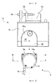
図2は、図1の循環装置本体の全体構成を示す斜視図である。図3は、図2循環装置本体における装置本体と循環ユニットとを分離した状態を示す平面図である。 FIG. 2 is a perspective view showing the overall configuration of the circulation device main body of FIG. FIG. 3 is a plan view showing a state in which the apparatus main body and the circulation unit in the circulation apparatus main body of FIG. 2 are separated.
図1〜図3を参照して、循環装置本体4は、前記各トロッカー2、3の間に連結された状態で、トロッカー3から腹腔J2内の気体を吸引するとともに、この気体を後述するフィルタを通してトロッカー2から排出することが可能とされている。
1 to 3, the circulation device main body 4 sucks the gas in the abdominal cavity J <b> 2 from the
具体的に、循環装置本体4は、前記各トロッカー2、3同士を連結するための循環ユニット9と、この循環ユニット9を着脱可能に構成された装置本体(本体部材)10とを備えている。
Specifically, the circulation device main body 4 includes a
循環ユニット9は、前記トロッカー3に一端が接続される吸引側チューブ11と、前記トロッカー2に一端が接続される排出側チューブ12と、これら吸引側チューブ11及び排出側チューブ12の他端がそれぞれ接続されるフィルタ保持部材14とを備えている。
The
吸引側チューブ11は、一対の先端チューブ15及び基端チューブ本体16と、これらチューブ15、16との間に設けられたトラップ部材(トラップ手段)17とを備えている。
The
このトラップ部材17は、図8に示すように、トラップ容器18と、このトラップ容器18に対しその開口を塞ぐように取り付けられる蓋部材19とを備えている。この蓋部材19の表面には、前記先端チューブ15が接続される取付部19a及び前記基端チューブ16が接続される取付部19bが形成されている一方、蓋部材19の裏面には、前記取付部19aからトラップ容器18の底部付近まで延びるノズル20が形成されている。したがって、先端チューブ15からノズル20を通してトラップ容器18内に水が流れ込んだ場合、トラップ容器18内に水が一杯になるまでの間、取付部19b(基端側チューブ16)に水が流れ込むのを阻止することができる。
As shown in FIG. 8, the
排出側チューブ12は、図6に示すように、チューブ本体21と、このチューブ本体21内に設けられた熱電対22及び熱線(発熱体)23とを備えている。熱電対22は、チューブ本体21内の温度を検出するためのものである。また、熱線23は、チューブ本体21内の温度が所望の温度となるように当該チューブ本体21内を加温するためのものである。
As shown in FIG. 6, the
図4は、図3のIV−IV線断面図である。図5は、図3のV−V線断面図である。図6は、図3のフィルタ保持部材14の一部を分解して示す斜視図である。図7は、図6の第3ケース部材の平面図である。
4 is a cross-sectional view taken along line IV-IV in FIG. 5 is a cross-sectional view taken along line VV in FIG. 6 is an exploded perspective view showing a part of the
図4〜図7を参照して、フィルタ保持部材14は、上下に重ねられて容器状の体をなす4つのケース部材(以下、区別するときは上から順に第1ケース部材24、第2ケース部材25、第3ケース部材26及び第4ケース部材27と称す)と、これらケース部材24〜27の内部に格納されたフィルタ28及び遠心羽根車29と、この遠心羽根車29の入力軸に連結された入力歯車30と、前記熱電対22及び熱線23にそれぞれ電気的に接続された電極31、電極32、電極33及び電極34(図6参照)とを備えている。
4 to 7, the
ケース部材24〜27は、その内部に前記フィルタ28の手前側の室S1と奥側の室S2が形成されるように、当該フィルタ28を保持するようになっている。手前側の室S1は前記吸引側チューブ11に連通する一方、前記奥側の室S2は前記排出側チューブ12に連通している。また、前記遠心羽根車29は、手前側の室S1内に設けられ、当該室S1から奥側の室S2へ向けて送風を行うことが可能とされている。
The
具体的に、第1ケース部材24と第2ケース部材25との間には、前記吸引側チューブ11から気体を導入するための吸引ポート35が形成されている。これら第1ケース部材24と第2ケース部材25との間の室には第3ケース部材26において上方に延びるスリーブ36が臨み、このスリーブ36を通して当該第3ケース部材の下面まで気体が導かれる。なお、このスリーブ36の下方において第3ケース部材26と第4ケース部材27との間に前記遠心羽根車29が設けられている。
Specifically, a
ここで、第3ケース部材26及び第4ケース部材27の構成について詳述する。第3ケース部材26は、図6及び図7に詳しく示すように、前記スリーブ36の周囲を取り囲む第1周壁37と、この第1周壁37のさらに外側を取り囲む第2周壁38と、第1周壁37と第2周壁38との間に形成されたバイパス流路39と、前記スリーブ36の下部から第1周壁37及び第2周壁38を連結する底板40とを備えている。
Here, the configuration of the
前記バイパス流路39の入口39aは、図4及び図6に示すように、前記底板40よりも下側で第3ケース部材26と第4ケース部材27との間に形成されている。そして、バイパス流路39は、前記入口39aから第1周壁37と第2周壁38との間のスペースで上方に傾斜して、最終的に前記底板40よりも上側で第1周壁37に形成された出口39bに到達するものとして第3ケース部材26に形成されている。
As shown in FIGS. 4 and 6, the
また、前記スリーブ36は、肩部36aを介して下部が上部よりも大きな直径寸法とされている一方、前記第1周壁37の内側面には内側に向けて突起が形成され、この突起の上面37aと前記肩部36aとが前記バイパス流路39の出口39bよりも高い位置で同じ高さとされている。そして、前記フィルタ28は、肩部36aと上面37a上に載置され、前記第2ケース部材25において下方に延びる内外一対の押圧筒25a及び押圧筒25bの下面により挟持されている。
Further, the
したがって、図4の矢印Y1に示すように前記スリーブ36を通って遠心羽根車29の外側に導かれた気体は、矢印Y2に示すように前記入口39aからバイパス流路39に導入される。そして、前記第1周壁37の外側を通って底板40の上方にある出口39b(フィルタ28の下方位置)に導かれた気体は、矢印Y3に示すようにフィルタ28を通り、矢印Y4に示すように前記外側の押圧筒25aに形成された切欠部25cを介して第3ケース部材26に形成された排出ポート41を通って前記排出側チューブ12内に導かれることになる。
Therefore, the gas guided to the outside of the
入力歯車30は、前記第4ケース部材27の底板42を貫通する遠心羽根車29の回転軸43に連結されている。つまり、入力歯車30は、ケース部材24〜27の外側に配置されている。
The
電極31〜34は、図6に示すように、第3ケース部材26の第2周壁38を貫通する孔26a、孔26b、孔26c及び孔26dを塞ぐように当該第2周壁38に固定されている。これら電極31、32は前記熱電対22のそれぞれに接続されているとともに、各電極33、34は前記熱線23のそれぞれに接続されている。
As shown in FIG. 6, the
そして、上述した循環ユニット9は、装置本体10に装着されることにより、前記遠心羽根車29の回転軸43に対する回転駆動力が供給されるとともに、前記各電極31〜34を介して熱電対22及び熱線23に対して電力が供給される。以下、装置本体10の具体的構成について説明する。
The
図2、図3及び図5を参照して、装置本体10は、前記フィルタ保持部材14を装着可能な凹部45が形成されたケース46と、このケース46に内蔵されたモータ47と、前記各電極31〜34に電力を供給するための複数のプローブ48と、各種設定値を入力操作するための入力部49と、これらモータ47、プローブ48及び入力部49に電気的に接続された制御部50とを備えている。
2, 3, and 5, the apparatus
ケース46は、凹部45の形成部分を除き、概ね直方体に形成された中空容器である。前記凹部45は、ケース46の上部前方の角部に設けられ、上方及び前方へ開く形状とされている。具体的に、凹部45は、フィルタ保持部材14を前方から挿入ことが可能な形状とされ、ケース46には、凹部45に挿入されたフィルタ保持部材14の後方角部14a(図3参照)を上方から覆う円弧状の縁部46aが形成されている。この縁部46aによってフィルタ保持部材14の上方への抜け止めが達成される。なお、前方への抜け止めは、凹部45内に臨んで配置された図外の爪がフィルタ保持部材14に係合することによって達成される。この前方への抜け止めは、ケース46の正面に設けられたノブ51の引っ張り操作によって解除することが可能とされている。
The
また、ケース46の背面には、後方に延びる一対の取付板52及び取付板53と、取付板52を貫く蝶ねじ54が設けられている。この蝶ねじ54は、取付板52に対する螺合深さを変えることにより、その先端を他方の取付板53に接離させることが可能とされている。したがって、この蝶ねじ54の先端部と取付板53との間に図外のポール等を挟持させることにより、ケース46をポールに取り付けることができる。
Further, on the back surface of the
モータ47は、図5に示すように、前記凹部45の下面を規定するケース46の天板55に取り付けられたモータ本体56と、前記天板55を上下に貫く出力軸57と、前記天板55の上方で出力軸57に連結された出力歯車58とを備えている。この出力歯車58は、凹部45内に挿入されたフィルタ保持部材14の入力歯車30と噛合可能となる位置に設けられている。
As shown in FIG. 5, the
各プローブ48は、前記凹部45の後面を規定するケース46の前板59を前後に貫通して設けられている。これらプローブ48は、それぞれ凹部45内に挿入されたフィルタ保持部材14の各電極31〜34に当接可能となる位置に設けられている。
Each
したがって、フィルタ保持部材14を凹部45内に挿入することにより、前記遠心羽根車29とモータ47とが駆動連結されるとともに、各電極31〜34が各プローブ48とそれぞれ電気的に接続されることになる。
Therefore, by inserting the
入力部49は、循環させるガスの風量、患者の腹腔J2内に戻すガスの目標温度等を入力可能に構成され、この入力値を後述する制御部50に出力するようになっている。
The
図9は、図5の制御部50の電気的構成を示すブロック図である。
FIG. 9 is a block diagram showing an electrical configuration of the
図9を参照して、制御部50は、前記入力部49による設定温度の入力操作を受けてガスの目標温度を設定する温度設定手段60と、この温度設定手段60により設定された温度に対応する電力を特定しこの電力を電源64から熱線23に供給する温度出力手段61と、前記熱電対22により検出結果に基づいてチューブ本体21内の温度を判定するとともにその結果を前記温度出力手段に出力する温度判定手段62とを備えている。
Referring to FIG. 9, the
温度設定手段60は、患者の体温に対応する温度の範囲内(例えば、35℃〜38℃の範囲内)で目標温度を設定することが可能とされている。 The temperature setting means 60 can set the target temperature within a temperature range corresponding to the patient's body temperature (for example, within a range of 35 ° C. to 38 ° C.).
温度出力手段61は、温度判定手段62からの入力信号に応じて熱線23に対する供給電力をフィードバック制御するようになっている。
The temperature output means 61 performs feedback control of the power supplied to the
また、制御部50は、前記入力部49による風量の入力操作を受けてモータ47に対する供給電力を調整するようになっている。
Further, the
以下、上記気腹ガス循環装置1の動作について、図1〜図4を参照して説明する。 Hereinafter, the operation of the pneumoperitone gas circulation apparatus 1 will be described with reference to FIGS.
まず、フィルタ保持部材14を装置本体10に装着し、当該装置本体10の入力部49を用いて患者の腹腔に戻すガスの温度及び、風量を設定する。次いで、前記入力部49による循環開始の操作が行われると、前記風量に対応する速度でモータ47が回転するとともに、前記温度に対応する電力が熱線23に供給される。
First, the
ガスの循環が行われている間には、排出側チューブ12のチューブ本体21内のガスの温度が熱電対22及び制御部50によって検出され、この検出温度に基づいて熱線23に供給される電力が調整される。
While the gas is being circulated, the temperature of the gas in the tube
以上説明したように、前記実施形態によれば、熱線23に電源64から電力を供給することにより、患者の体温に対応する温度となるように加温されたガスを排出側チューブ12を通して患者の腹腔J2内に戻すことができるので、温度低下が生じているガスをそのまま患者の腹腔J2内に戻す可能性のある従来技術と異なり、術中における患者の状態管理に余分な労力が生じるのを防止することができる。
As described above, according to the embodiment, by supplying electric power from the
また、前記実施形態では、ガスを加温した状態で排出することにしているので、少なくとも排出側チューブ12のうちトロッカー2の近傍位置における気体の結露を防止することができる。
Moreover, in the said embodiment, since it is supposed that it discharges | emits in the state heated, the dew condensation of the gas in the position near the
したがって、本発明によれば、結露の発生を抑制しながら術中における患者の状態管理の労力増加を防止することができる。 Therefore, according to the present invention, it is possible to prevent an increase in the labor of state management of the patient during the operation while suppressing the occurrence of condensation.
前記実施形態によれば、遠心羽根車29をモータ47により回転させることによって、トロッカー3から吸引側チューブ11を通してガスをフィルタ保持部材14まで導き、このガスをフィルタ28を通した上で排出側チューブ12に導いてトロッカー3から排出することができる。
According to the embodiment, by rotating the
前記実施形態によれば、熱線23により排出側チューブ12内のガスを加温するようにしているので、加温範囲を最小限に抑えて加温に要するエネルギーを節約することができる。
According to the embodiment, since the gas in the
前記実施形態によれば、吸引側チューブ11がトラップ部材17を有しているため、上述のように加温範囲を最小限に抑えて省エネを図りながら、吸引側チューブ11内に結露が生じた場合であってもその水滴をトラップ部材17により捕らえて、当該水滴が循環装置本体4内で流通するのを阻止することができる。
According to the embodiment, since the
前記実施形態によれば、熱電対22により検出されたガスの実際の温度に応じて熱線23に供給する電力をフィードバック制御することができるので、より精緻な温度管理を行うことができる。
According to the embodiment, since the power supplied to the
前記実施形態によれば、フィルタ保持部材14と装置本体10とを着脱することにより、遠心羽根車29の回転軸43とモータ47の出力軸とを連結又は解除することができるので、このフィルタ保持部材14、吸引側チューブ11、排出側チューブ12及び遠心羽根車29を備えた循環ユニット9を使い捨てにする一方で、この遠心羽根車29を回転駆動させるモータ47を含む装置本体10を使い回しする構成を確立することができる。
According to the embodiment, the
したがって、前記実施形態によれば、比較的高価なモータ47を使い回すとともに循環ユニット9を交換することによりガスの流れを形成することができるため、使用者にとってコストパフォーマンスが高く、使用手順が容易な製品とすることができる。
Therefore, according to the embodiment, since the gas flow can be formed by using the relatively
また、前記実施形態によれば、フィルタ保持部材14と装置本体10とを着脱することにより、熱線23と電源64との電気的な接続又は解除を行うことができるので、このフィルタ保持部材14、吸引側チューブ11、排出側チューブ12及び熱線23を備えた循環ユニット9を使い捨てにする一方で、この熱線23に電力を供給する電源64を含む装置本体10を使い回しする構成を確立することができる。
In addition, according to the embodiment, the
したがって、前記実施形態によれば、比較的高価な電源64を使い回すとともに循環ユニット9を交換することにより排出側チューブ12内のガスの加温機能を得ることができるため、使用者にとってコストパフォーマンスが高く、使用手順が容易な製品とすることができる。
Therefore, according to the embodiment, since the function of heating the gas in the
また、前記実施形態に係る気腹ガス循環装置1によれば、前記循環装置本体4により得られる効果に加えて、吸引側のトロッカー3及び排出側のトロッカー2を含む気腹ガスの循環に要する一式の用具を備えているため、既にトロッカー2、3が患者に穿刺されている状況でなくても即座に気腹ガスの循環を行うことができる。
Further, according to the pneumoperitone gas circulator 1 according to the embodiment, in addition to the effects obtained by the circulator main body 4, it is necessary to circulate pneumoperitone gas including the
さらに、前記気腹ガス循環装置1では、排出側のトロッカー2が当該トロッカー2に挿入された内視鏡103に対し排出側チューブ12から導かれたガスを吹き付けることが可能となるように構成されているため、当該ガスによって内視鏡103を温めることができ、当該内視鏡103のレンズのくもりを抑制することができる。つまり、前記気腹ガス循環装置1では、患者の体温に対応する温度に加温されたガスを、既に患者の腹腔J2内に挿入されている内視鏡103に吹き付けることにより、当該内視鏡103を患者の体温に対応する温度に温めて当該内視鏡103の温度と腹腔J2内の温度との温度差を低減することができるため、内視鏡103のレンズがくもるのを抑制することができる。
Further, the insufflation gas circulating apparatus 1 is configured such that the
なお、前記気腹ガス循環装置1では、気腹装置8を別途設けたシステムを採用しているが(図1参照)、図10に示すように、気腹ガス循環装置1と気腹装置8とを組合せた気腹ガス循環システム70を構築することも可能である。
The insufflation gas circulation device 1 employs a system in which the
つまり、気腹ガス循環システム70は、前記気腹ガス循環装置1に加えて排出側チューブ12の途中に介在された気腹装置8をさらに備えた構成となっている。このような構成とすることにより、気腹装置8からトロッカー2を介してCO2ガスを患者の腹腔J2内に導入することができるとともに、前記気腹ガス循環装置1と気腹装置8とを並行して用いる場合と異なり、気腹装置8を接続するためのトロッカー7を腹壁J1に穿刺しなくて済むことになる。したがって、この気腹ガス循環システム70によれば、患者への負担をより低減しながら、上記実施形態と同様の効果を奏することが可能となる。
That is, the insufflation
なお、図10の実施形態では、排出側チューブ12の途中部に気腹装置8を介在させた構成について説明しているが、気腹装置8と循環装置本体4とを一体とし、これに排出側チューブ12を接続した構成とすることも可能である。
In the embodiment of FIG. 10, the configuration in which the
また、図10の実施形態では、排出側チューブ12の途中に気腹装置8が介在された構成について説明しているが、排出側チューブ12の途中部に少なくとも3つのポートを有する継手を介在させ、この継手の2つのポートを利用して排出側チューブ12を連結する一方、別のポートに他のチューブを接続し、このチューブに気腹装置8を接続することもできる。つまり、気腹装置8に接続されたチューブを、継手を介して排出側チューブ12に合流させることもできる。なお、前記継手としては、少なくとも3つのポートがあれば、その形状が問われることはない。
In the embodiment of FIG. 10, the configuration in which the
このように気腹装置8を排出側チューブ12の途中部に合流させるようにした構成とした場合には、排出側チューブ12を介した気腹ガスの循環機能という気腹ガス循環装置1本来の機能を発揮させたまま気腹装置8を排出側チューブ12から取外してそのメンテナンスを行うことができる。また、このように取り外しの自由度が高いことから、上述した図1のような接続ラインと、排出側チューブ12に合流させる接続ラインとの切換を容易に行うことができるという利点もある。
Thus, when it is set as the structure which merged the
J1 腹壁
1 気腹ガス循環装置
2 トロッカー(排出側トロッカー)
3 トロッカー(吸引側トロッカー)
4 循環装置本体
9 循環ユニット
10 装置本体(本体部材)
11 吸引側チューブ
12 排出側チューブ
14 フィルタ保持部材(保持部材)
17 トラップ部材(トラップ手段)
22 熱電対(検出手段)
23 熱線(発熱体)
28 フィルタ
29 遠心羽根車
47 モータ
48 プローブ
50 制御部
60 温度設定手段
61 温度出力手段
62 温度判定手段
64 電源
70 気腹ガス循環システム
J1 abdominal wall 1 pneumoperitone
3 trocar (suction side trocar)
4 Circulating
11
17 Trap member (trap means)
22 Thermocouple (detection means)
23 Heating wire (heating element)
28
Claims (8)
前記他方のトロッカーから排出される気体が患者の体温に対応する温度となるように、前記気体を加温する加温手段と、
前記一方のトロッカーに一端が接続される吸引側チューブと、
前記他方のトロッカーに一端が接続される排出側チューブと、
これら吸引側チューブ及び排出側チューブの他端がそれぞれ接続されるとともに前記フィルタを保持する保持部材と、
前記吸引側チューブから気体を吸引するとともにこの気体を前記フィルタを通して前記排出側チューブから排出させる気体の流れを形成する送風手段とを備え、
前記加温手段は、吸引側チューブ、排出側チューブの少なくとも一方に設けられ、電力の供給を受けて発熱する発熱体と、この発熱体に電力を供給する電源とを備え、
前記気腹ガス循環装置は、前記保持部材と着脱可能に構成されているとともに前記電源が設けられた本体部材をさらに備え、この本体部材に対し前記保持部材が装着されることにより、前記電源と発熱体とが電気的に接続されることを特徴とする気腹ガス循環装置。 A pair of trocars that can puncture the patient's abdominal wall can be connected to each other, and while being connected to each trocar, the gas can be sucked from one trocar and discharged from the other trocar through the filter. A possible insufflation gas circulation device,
A heating means for heating the gas so that the gas discharged from the other trocar has a temperature corresponding to the body temperature of the patient ;
A suction side tube having one end connected to the one trocar;
A discharge side tube having one end connected to the other trocar;
The other end of each of the suction side tube and the discharge side tube is connected and holding the filter, and
A blower for forming a gas flow for sucking gas from the suction side tube and discharging the gas from the discharge side tube through the filter;
The heating means is provided in at least one of the suction side tube and the discharge side tube, and includes a heating element that generates heat upon receipt of electric power, and a power source that supplies electric power to the heating element,
The insufflation gas circulation device further includes a main body member configured to be detachable from the holding member and provided with the power source, and the holding member is attached to the main body member so that the power source An insufflation gas circulation device characterized by being electrically connected to a heating element .
前記他方のトロッカーから排出される気体が患者の体温に対応する温度となるように、前記気体を加温する加温手段と、Heating means for heating the gas so that the gas discharged from the other trocar has a temperature corresponding to the body temperature of the patient;
前記一方のトロッカーに一端が接続される吸引側チューブと、A suction side tube having one end connected to the one trocar;
前記他方のトロッカーに一端が接続される排出側チューブと、A discharge side tube having one end connected to the other trocar;
これら吸引側チューブ及び排出側チューブの他端がそれぞれ接続されるとともに前記フィルタを保持する保持部材と、The other end of each of the suction side tube and the discharge side tube is connected and holding the filter, and
前記吸引側チューブから気体を吸引するとともにこの気体を前記フィルタを通して前記排出側チューブから排出させる気体の流れを形成する送風手段とを備え、A blower for forming a gas flow for sucking gas from the suction side tube and discharging the gas from the discharge side tube through the filter;
前記保持部材は、前記フィルタを挟んで内部に二つの室が形成されるように当該フィルタを格納するように構成され、The holding member is configured to store the filter so that two chambers are formed inside the filter,
前記送風手段は、前記二つの室のうち少なくとも何れか一方の室内に設けられ、前記各室の一方から他方への気体の流れを形成可能な羽根車と、この羽根車を回転駆動するための駆動源とを備え、The air blowing means is provided in at least one of the two chambers, and is capable of forming a gas flow from one of the chambers to the other, and for rotating the impeller. A drive source,
前記気腹ガス循環装置は、前記保持部材と着脱可能に構成されているとともに前記駆動源が設けられた本体部材をさらに備え、この本体部材に対し前記保持部材が装着されることにより、前記駆動源の出力軸と前記羽根車の入力軸とが回転可能に噛合することを特徴とする気腹ガス循環装置。The insufflation gas circulation device further includes a main body member configured to be detachable from the holding member and provided with the driving source, and the driving member is mounted by attaching the holding member to the main body member. An insufflation gas circulation device characterized in that an output shaft of a source and an input shaft of the impeller are rotatably meshed with each other.
Priority Applications (1)
| Application Number | Priority Date | Filing Date | Title |
|---|---|---|---|
| JP2007164891A JP5111953B2 (en) | 2007-06-22 | 2007-06-22 | Insufflation gas circulation device and insufflation gas circulation system provided with the same |
Applications Claiming Priority (1)
| Application Number | Priority Date | Filing Date | Title |
|---|---|---|---|
| JP2007164891A JP5111953B2 (en) | 2007-06-22 | 2007-06-22 | Insufflation gas circulation device and insufflation gas circulation system provided with the same |
Publications (2)
| Publication Number | Publication Date |
|---|---|
| JP2009000340A JP2009000340A (en) | 2009-01-08 |
| JP5111953B2 true JP5111953B2 (en) | 2013-01-09 |
Family
ID=40317388
Family Applications (1)
| Application Number | Title | Priority Date | Filing Date |
|---|---|---|---|
| JP2007164891A Expired - Fee Related JP5111953B2 (en) | 2007-06-22 | 2007-06-22 | Insufflation gas circulation device and insufflation gas circulation system provided with the same |
Country Status (1)
| Country | Link |
|---|---|
| JP (1) | JP5111953B2 (en) |
Families Citing this family (7)
| Publication number | Priority date | Publication date | Assignee | Title |
|---|---|---|---|---|
| US20130197315A1 (en) * | 2010-04-12 | 2013-08-01 | Life Care Medical Devices, Ltd. | Device and method for lifting abdominal wall during medical procedure |
| JPWO2016140039A1 (en) * | 2015-03-04 | 2017-04-27 | オリンパス株式会社 | Medical treatment system |
| US10493220B2 (en) | 2015-07-02 | 2019-12-03 | Northgate Technologies Inc. | Gas recirculation system and method |
| CN108135635B (en) * | 2015-10-07 | 2021-10-26 | 奥林巴斯株式会社 | Surgical device and smoke evacuation system |
| US11027078B2 (en) * | 2018-09-21 | 2021-06-08 | Conmed Corporation | Multi-modal five lumen gas circulation system for use in endoscopic surgical procedures |
| CN110743262B (en) * | 2019-10-29 | 2022-04-22 | 珠海市司迈科技有限公司 | Integrated intra-cavity gas circulation treatment device for laparoscopic surgery |
| JP7503323B2 (en) | 2022-03-17 | 2024-06-20 | 株式会社八光 | Pressure stabilizing reservoir for surgical cavity |
Family Cites Families (6)
| Publication number | Priority date | Publication date | Assignee | Title |
|---|---|---|---|---|
| JP2544880B2 (en) * | 1992-10-16 | 1996-10-16 | オリンパス光学工業株式会社 | Smoke removal system for pneumoperitoneum |
| US6234635B1 (en) * | 1998-07-30 | 2001-05-22 | Michael R. Seitzinger | Method for preventing laparoscope fogging |
| US6544210B1 (en) * | 1998-10-22 | 2003-04-08 | Gregory J. Trudel | Disposable laparoscopic smoke evacuation system |
| US6685665B2 (en) * | 2000-09-08 | 2004-02-03 | Pall Corporation | Cannula assembly |
| JP2004159688A (en) * | 2002-11-08 | 2004-06-10 | Olympus Corp | Air blowing appliance |
| US7704223B2 (en) * | 2003-10-07 | 2010-04-27 | Northgate Technologies Inc. | System and method for delivering a substance to a body cavity |
-
2007
- 2007-06-22 JP JP2007164891A patent/JP5111953B2/en not_active Expired - Fee Related
Also Published As
| Publication number | Publication date |
|---|---|
| JP2009000340A (en) | 2009-01-08 |
Similar Documents
| Publication | Publication Date | Title |
|---|---|---|
| JP5111953B2 (en) | Insufflation gas circulation device and insufflation gas circulation system provided with the same | |
| WO2016140039A1 (en) | Insertion tool and medical treatment system | |
| US6544210B1 (en) | Disposable laparoscopic smoke evacuation system | |
| US11712258B2 (en) | Tissue resection systems including fluid outflow management | |
| BR112012020296B1 (en) | Ultrasonic surgical instrument | |
| JP2007513695A (en) | Suction sleeve and treatment device provided with such suction sleeve | |
| WO2019148346A1 (en) | Surgical access system | |
| KR101297637B1 (en) | Electrocautery that has both gas suction and gas jet mechanism | |
| JP6755348B2 (en) | Detachable fluid reservoir and ultrasonic surgical instruments containing it | |
| CN114344669A (en) | Irrigation suction tube and surgical device | |
| JP2022500178A (en) | Multimode 5 lumen gas circulation system for use in endoscopic surgery | |
| TWI682760B (en) | Auxiliary system with a removal device for surgery | |
| JP2007296164A (en) | Endoscopic system | |
| CN108697309B (en) | Medical tubing component | |
| WO2017057030A1 (en) | Circulation-type smoke ventilator | |
| CN106344123A (en) | Self-purging bone saw for orthopedic surgery | |
| WO2018180074A1 (en) | Insertion device and method for operating insertion device | |
| EP3487381B1 (en) | Channel device for a endoscope assembly | |
| JP3927204B2 (en) | Endoscope | |
| KR102011503B1 (en) | Harmonic scalpel for surgical operation having blade which has improved cooling efficiency and operability | |
| KR101586813B1 (en) | Electro-surgical apparatus | |
| JP2004159688A (en) | Air blowing appliance | |
| CN217186347U (en) | Puncture device and surgical system | |
| CN220046089U (en) | Demisting device for laparoscopic surgery | |
| KR20200109702A (en) | Medical apparatus module inserting into body |
Legal Events
| Date | Code | Title | Description |
|---|---|---|---|
| A621 | Written request for application examination |
Free format text: JAPANESE INTERMEDIATE CODE: A621 Effective date: 20100618 |
|
| A977 | Report on retrieval |
Free format text: JAPANESE INTERMEDIATE CODE: A971007 Effective date: 20120528 |
|
| A131 | Notification of reasons for refusal |
Free format text: JAPANESE INTERMEDIATE CODE: A131 Effective date: 20120612 |
|
| A521 | Written amendment |
Free format text: JAPANESE INTERMEDIATE CODE: A523 Effective date: 20120806 |
|
| TRDD | Decision of grant or rejection written | ||
| A01 | Written decision to grant a patent or to grant a registration (utility model) |
Free format text: JAPANESE INTERMEDIATE CODE: A01 Effective date: 20120918 |
|
| A01 | Written decision to grant a patent or to grant a registration (utility model) |
Free format text: JAPANESE INTERMEDIATE CODE: A01 |
|
| A61 | First payment of annual fees (during grant procedure) |
Free format text: JAPANESE INTERMEDIATE CODE: A61 Effective date: 20121010 |
|
| FPAY | Renewal fee payment (event date is renewal date of database) |
Free format text: PAYMENT UNTIL: 20151019 Year of fee payment: 3 |
|
| R150 | Certificate of patent or registration of utility model |
Ref document number: 5111953 Country of ref document: JP Free format text: JAPANESE INTERMEDIATE CODE: R150 Free format text: JAPANESE INTERMEDIATE CODE: R150 |
|
| R250 | Receipt of annual fees |
Free format text: JAPANESE INTERMEDIATE CODE: R250 |
|
| R250 | Receipt of annual fees |
Free format text: JAPANESE INTERMEDIATE CODE: R250 |
|
| R250 | Receipt of annual fees |
Free format text: JAPANESE INTERMEDIATE CODE: R250 |
|
| R250 | Receipt of annual fees |
Free format text: JAPANESE INTERMEDIATE CODE: R250 |
|
| LAPS | Cancellation because of no payment of annual fees |