JP5111890B2 - Movable flat cable - Google Patents
Movable flat cable Download PDFInfo
- Publication number
- JP5111890B2 JP5111890B2 JP2007048630A JP2007048630A JP5111890B2 JP 5111890 B2 JP5111890 B2 JP 5111890B2 JP 2007048630 A JP2007048630 A JP 2007048630A JP 2007048630 A JP2007048630 A JP 2007048630A JP 5111890 B2 JP5111890 B2 JP 5111890B2
- Authority
- JP
- Japan
- Prior art keywords
- flat cable
- elastic material
- bent
- resin elastic
- cable
- Prior art date
- Legal status (The legal status is an assumption and is not a legal conclusion. Google has not performed a legal analysis and makes no representation as to the accuracy of the status listed.)
- Active
Links
Images


Description
この発明は、工作機械や組立てロボット等の可動部を有する機器において、その可動部に電力を供給したり、制御信号を伝達したりするための可動用フラットケーブルに関する。 The present invention relates to a movable flat cable for supplying electric power to a movable part or transmitting a control signal in an apparatus having a movable part such as a machine tool or an assembly robot.
工作機械や組立てロボット等の機器は、その加工台や可動アーム等の作業ユニットが自在に移動して加工作業が行われる。その作業ユニットは、モータ、ソレノイド、光源等の様々な部品が組み込まれており、その各部品には、制御盤等の固定物からケーブルを介して電力の供給や制御信号の伝達がなされる。 Machine tools, assembly robots, and other devices perform processing operations by freely moving work units such as processing tables and movable arms. The work unit incorporates various components such as a motor, a solenoid, and a light source, and each component is supplied with electric power and a control signal from a fixed object such as a control panel via a cable.
その際、作業ユニットが移動するのにつれて、その作業ユニットと固定物との距離が変化するため、上記ケーブルは、作業ユニットの移動につれて固定物に対して引き出されたり、引き戻されたりする。このとき、ケーブルをその長さ方向において折り返して屈曲させ、ケーブルの引き出し・引き戻しにつれてその屈曲位置を移動させて対応させるのが一般的であり、その屈曲位置が移動する際、ケーブルが蛇行したりして、その引き出し・引き戻しが円滑になされない恐れがある。
この蛇行を防止するため、チェーン状のケーブルベアの内側に上記ケーブルを収納し、そのケーブルベアによりケーブルを案内することで、ケーブルの屈曲部の移動をその引き出し・引き戻し方向に規制したものがある(例えば、特許文献1参照)。
In order to prevent this meandering, the cable is housed inside a chain-shaped cable carrier, and the cable is guided by the cable carrier so that the movement of the bent portion of the cable is restricted in the pulling / retracting direction. (For example, refer to Patent Document 1).
上記ケーブルベアを使用したケーブルによる電力・信号伝達は、そのケーブルベアの分、嵩高くなっている。一方、今日、各種機械の小型化が進められており、その小型化に伴い、上記ケーブルベアの省スペース化が望まれている。
その省スペース化には、ケーブルベアを無くすことが考えられるが、上記のケーブルの蛇行が問題となる。
The power / signal transmission by the cable using the cable bear is bulky because of the cable bear. On the other hand, downsizing of various machines is being promoted today, and with the miniaturization, space saving of the cable bear is desired.
In order to save the space, it is conceivable to eliminate the cable track, but the meandering of the cable is a problem.
この発明は、上記の実情に鑑み、ケーブル自体に屈曲時の方向性を維持するようにして、上記ケーブルベアの使用を省略し得るようにしたのである。 In view of the above situation, the present invention maintains the directionality of the cable itself when bent, so that the use of the cable bear can be omitted.
上記の課題を解決するため、この発明は、まず、電線等の複数の線状体を並列に配置し、その外周を被覆樹脂弾性材で被覆して上記各線状体を一体にしたフラットケーブルとしたのである。
フラットケーブルは、その長さ方向において折り返して屈曲をさせると(図2、図3の状態)、その屈曲部を除いてフラット状態を維持しつつ屈曲するとともに、屈曲が解消されれば、扁平なフラット形状に復帰する。このため、フラットケーブルはその屈曲方向に蛇行することなく追従する。
In order to solve the above-described problems, the present invention first includes a flat cable in which a plurality of linear bodies such as electric wires are arranged in parallel and the outer periphery thereof is covered with a covering resin elastic material, and the linear bodies are integrated. It was.
When the flat cable is bent in the length direction and bent (the state shown in FIGS. 2 and 3), the flat cable is bent while maintaining the flat state except for the bent portion. Return to flat shape. For this reason, the flat cable follows without bending in the bending direction.
つぎに、この発明は、上記複数の線状体を、上記フラットケーブルの断面厚さ方向の上下にずらして配置し、その複数の線状体は、その抗張力が上記被覆樹脂弾性材の抗張力に比べて大きく設定されたものとしたのである。
複数の線状体が上記断面厚さ方向の上下にずれていれば、このフラットケーブルがその長さ方向において折り返されて屈曲しようとする際、各線状体はそれぞれの上記断面厚さ方向の上下にずれた位置に対応した、それぞれ異なる曲率で屈曲することとなる。この異なる曲率で屈曲させるには、屈曲部の内側(曲率が小さい)の線状体に対して、外側(曲率が大きい)の線状体はより多く引き伸ばされる必要がある。
しかし、この各線状体には引き伸ばされるのに対する抵抗力、所謂、抗張力があるため、曲率の差に対応した長さの分だけケーブルを引き伸ばすことは容易ではない。このことから、このフラットケーブルは、例え、屈曲を生じさせる外力が作用したとしても屈曲し難く、通常のフラットケーブルに比べて元の形状を保持する作用が強いため、その保形性を維持しつつ屈曲することとなり、屈曲による蛇行はさらに抑制される。
Next, according to the present invention, the plurality of linear bodies are arranged so as to be shifted up and down in the cross-sectional thickness direction of the flat cable, and the plurality of linear bodies have a tensile strength equal to that of the coated resin elastic material. It was set to be larger than that.
If a plurality of linear bodies are displaced up and down in the cross-sectional thickness direction, when the flat cable is folded in the length direction and is bent, each linear body is vertically moved in the cross-sectional thickness direction. Therefore, it bends with different curvatures corresponding to the positions shifted to each other. In order to bend with this different curvature, the linear body on the outer side (large curvature) needs to be stretched more than the linear body on the inner side (small curvature) of the bent portion.
However, since each of these linear bodies has a resistance to stretching, so-called tensile strength, it is not easy to stretch the cable by the length corresponding to the difference in curvature. For this reason, this flat cable is difficult to bend even if an external force that causes bending is applied, and has a stronger action of retaining the original shape than a normal flat cable, so that its shape retention is maintained. Therefore, the meandering due to the bending is further suppressed.
一方、このフラットケーブルに上記屈曲方向の外力を意図的に負荷すれば、被覆樹脂が弾性材からなるため、その屈曲につれて、各線状体が同一平面上に近づくように上記被覆樹脂弾性材が変形してその屈曲を許容し、屈曲が解消されれば、上記被覆樹脂弾性材の復元力により、各線状体が元の位置に復帰する。その屈曲の際、複数の線状体はその抗張力が上記被覆樹脂弾性材の抗張力に比べて大きく設定されているため、主として被覆樹脂弾性材が変形を許容して各線状体を同一平面上に近付ける作用を行う(図2の屈曲断面9a参照)。
線状体と被覆樹脂弾性材の抗張力は、保形性と屈曲性が両立し得る物性値の範囲を考慮して、この発明の作用をなし得るように、実験等によって適宜に設定する。
このように、このフラットケーブルは、保形性を高めることによる屈曲性は損なわれず、保形性と屈曲性が両立したものであるため、蛇行することなく、その長さ方向において折り返した屈曲を円滑にさせることができる。
On the other hand, if the external force in the bending direction is intentionally applied to the flat cable, the coating resin is made of an elastic material. Therefore, as the bending is bent, the coating resin elastic material is deformed so that each linear body approaches the same plane. Then, if the bending is allowed and the bending is eliminated, each linear body returns to the original position by the restoring force of the covering resin elastic material. At the time of bending, since the tensile strength of the plurality of linear bodies is set to be larger than the tensile strength of the coated resin elastic material, the coated resin elastic material is allowed to deform mainly so that the linear bodies are placed on the same plane. An approaching action is performed (see the
The tensile strength of the linear body and the coated resin elastic material is appropriately set by experiment or the like so that the action of the present invention can be achieved in consideration of a range of physical property values in which shape retention and flexibility are compatible.
In this way, this flat cable does not impair the bendability by improving the shape retaining property, and has both shape retaining property and bendability. Therefore, the flat cable can be bent in the length direction without meandering. It can be made smooth.
この発明の構成としては、複数本の線状体を並列に配置し、その外周を被覆樹脂弾性材で被覆して上記各線状体を一体に連結した可動用フラットケーブルであって、上記複数の線状体を、フラットケーブルの断面厚さ方向の上下にずらして配置し、その複数の線状体はその抗張力が上記被覆樹脂弾性材の抗張力に比べて大きく設定されて、このフラットケーブルがその長さ方向において折り返されて屈曲する際、その屈曲部において、各線状体が同一平面上に近づくように上記被覆樹脂弾性材が変形してその屈曲を許容し、屈曲が解消されれば、上記被覆樹脂弾性材の復元力により、各線状体が元の位置に復帰するものを採用することができる。 As a configuration of the present invention, there is provided a movable flat cable in which a plurality of linear bodies are arranged in parallel, the outer periphery thereof is covered with a covering resin elastic material, and the linear bodies are integrally connected. The linear body is arranged so as to be shifted up and down in the cross-sectional thickness direction of the flat cable, and the tensile strength of the plurality of linear bodies is set larger than the tensile strength of the coated resin elastic material. When bent and bent in the length direction, the coated resin elastic material is deformed so that each linear body approaches the same plane at the bent portion, and the bending is allowed. A material in which each linear body returns to its original position by the restoring force of the covering resin elastic material can be employed.
上記線状体には、電力供給電線、信号伝達電線等の種々の電線(ケーブルも含む)や、光ファイバー(ケーブルも含む)等の通信線条体や、水、空気、油等を流通させるチューブ等の管状体等のように、従来、可動用ケーブルに内装されていた種々のものを採用でき、この発明では、その各線状体の複数本、例えば、電線を複数本、又は、電線と管状体を少なくとも一つ有する複数本等と種々の組み合わせの複数本を並列に配置したものとする。 The linear body includes various wires (including cables) such as power supply wires and signal transmission wires, communication wires such as optical fibers (including cables), and tubes through which water, air, oil, etc. circulate. Conventionally, it is possible to employ various types of elements that have been internally mounted on a movable cable, such as a tubular body. In this invention, a plurality of each linear body, for example, a plurality of wires, or a wire and a tube Assume that a plurality of bodies having at least one body and a plurality of various combinations are arranged in parallel.
上記各線状体をフラットケーブルの断面厚さ方向の上下にずらした態様としては、上記保形性を有効に発揮するものであれば、何れでも良いが、例えば、各線状体を円弧線上に位置させたり、W字の線上に位置させたりする。そのW字の線上の位置は、各頂点のみならず、その途中の線上等と任意である。 As an aspect in which each linear body is shifted up and down in the cross-sectional thickness direction of the flat cable, any one can be used as long as it effectively exhibits the shape retaining property. For example, each linear body is positioned on an arc line. Or positioned on a W-shaped line. The position on the W-shaped line is arbitrary not only on each vertex but also on the middle line.
上記線状体の数は適宜選択できるが、2本であると、保形性をあまり望めないので、3本以上、好ましくは5本以上とする。例えば、ロボットの可動部への電力供給と信号伝達をこのフラットケーブルで行う場合、電力線を3本、信号線を2本の計5本を設けることができる。
また、このフラットケーブルの幅方向(厚さ方向に対して直角方向)において上記線状体の配置をその幅方向の中心線に対して対称とすれば、長さ方向における屈曲を生じさせる外力が作用した際の屈曲がスムーズであるとともに、蛇行もし難いものとなる。上記幅方向に蛇行しようとする際のその幅方向両側の抗力が同じであるため、蛇行し難く、一方、屈曲はスムーズになされるからである。さらに、上記線状体の並列配置は1層に限らず、その厚さ方向の上下に2層以上設けた多層構造とすることもできる。
The number of the linear bodies can be selected as appropriate, but if it is 2, shape retention cannot be expected so much, so it is 3 or more, preferably 5 or more. For example, when the power supply and signal transmission to the movable part of the robot are performed with this flat cable, a total of five power lines and two signal lines can be provided.
Further, if the arrangement of the linear bodies is symmetric with respect to the center line in the width direction in the width direction (perpendicular to the thickness direction) of the flat cable, an external force that causes bending in the length direction is generated. The bending when acting is smooth and difficult to meander. This is because the drag on both sides in the width direction when the meandering in the width direction is the same, it is difficult to meander, while the bending is performed smoothly. Furthermore, the parallel arrangement of the linear bodies is not limited to a single layer, and a multilayer structure in which two or more layers are provided above and below in the thickness direction can also be employed.
この発明は、以上のように、並列配置の線状体を厚さ方向の上下にずらすとともに、線状体と被覆樹脂弾性材との間の抗張力を異ならせたので、保形性が高く、しかも、屈曲の際に生じる蛇行も極力抑制される。そのため、ケーブルベアを必要とせずに、屈曲時の蛇行のないものとし得る。 As described above, the present invention, as described above, has shifted linearly arranged linear bodies up and down in the thickness direction and has different tensile strengths between the linear bodies and the covering resin elastic material, so that the shape retention is high, Moreover, meandering that occurs during bending is suppressed as much as possible. Therefore, it is possible to avoid meandering during bending without the need for a cable bear.
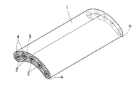
この発明の一実施形態を図1に示して説明すると、このフラットケーブル1は、導体3を樹脂被覆2した5本の絶縁電線4を円弧線c上に並んで配置し、その外周を樹脂弾性材である軟質ポリ塩化ビニル5で両端を除いて同一厚さで円弧状に被覆したものである。この樹脂弾性材として、軟質ポリ塩化ビニル以外にポリエステル系・シリコン系・スチレン系等の熱可塑性エラストマーやゴムなどが使用できる。
このフラットケーブル1は、各絶縁電線4が円弧線c上に位置することから、そのフラットケーブル断面厚さ方向の上下にずらして配置され、各絶縁電線4はその導体3が銅からなるため、その抗張力は樹脂である軟質ポリ塩化ビニル5の抗張力に比べて著しく大きくなっている。また、幅方向(厚さ方向に対して直角方向)において各絶縁電線4はその中央の絶縁電線4(幅方向の中心線)に対して対称に配置されている。
An embodiment of the present invention will be described with reference to FIG. 1. In this
Since each insulated
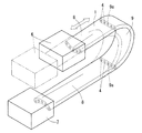
このフラットケーブル1は、例えば、図2に示すように、その長さ方向において折り返した構成によって、作業ユニット6と電力の供給源7とを接続する。この構成においては、フラットケーブル1の一端が工作機械等に固定された電力の供給源7に水平に接続され、他端が作業ユニット6に水平に接続され、その作業ユニット6が水平方向へ往復運動(同図中の白抜き矢印)することによって、作業ユニット6に設けられた加工ツール等で加工等の作業を行う。
その際、フラットケーブル1が水平に配置されている2箇所の水平部分8、8においては、このフラットケーブル1が有する保形性によってこのフラットケーブル1は曲がることなくほぼ水平に維持される。
For example, as shown in FIG. 2, the
At that time, in the two
また、2箇所の水平部分8、8の間においては、フラットケーブル1に屈曲を生じさせる外力が作用し、その部分で屈曲が生じる。この屈曲が生じた屈曲部分9では、作業ユニット6と電力の供給源7との位置関係に対応して、このフラットケーブル1が180度方向転換している。
Further, between the two
この屈曲部分9の屈曲断面9aにおいては、各絶縁電線4が可撓性を有する軟質ポリ塩化ビニル5で一体に成形され、かつ各絶縁電線4の抗張力が大きいため、屈曲を生じさせる外力が作用することにより、軟質ポリ塩化ビニル5が、各絶縁電線4がほぼ同一平面上に並ぶように変形する。これにより、屈曲部分9における各絶縁電線4の曲率はほぼ同一となって、円滑に屈曲するとともに、作業ユニット6の移動につれてその屈曲部分9が円滑に移行してその移動が円滑になされる。
In the
このフラットケーブル1は、絶縁電線4の円弧線上の配置が、円弧の膨らみを上記屈曲の内側にした状態(図2参照)、あるいは、円弧の膨らみを上記屈曲の外側にした状態のいずれの構成も適用できる。
In the
この各絶縁電線4は軟質ポリ塩化ビニル等の樹脂弾性材5とともに押出し成形して一体にされる。また、この成形の他の方法として、図3に示すように、絶縁電線4と介在13を縦添え又は撚り合わせたもの、各絶縁電線4のみを縦添え又は撚り合わせたものを樹脂弾性材5で被覆すると共にチューブ11を形成し、それらをその被覆時に一体成形したウエブ状連結部12で一体にする(連結する)こともできる。チューブ11は樹脂弾性材5によらず別物(例えば、樹脂チューブ)で構成することもできる。さらに、絶縁電線4の導体3を被覆する樹脂被覆2を加熱によって融着したり、弾性を有する接着剤等を用いたりして、各絶縁電線4を一体にすることもできる。
図3に示すフラットケーブル1においては、その長さ方向において折り返されて屈曲すると、その屈曲部分において各絶縁電線4が同一平面上に位置するように樹脂弾性材5からなるウエブ状連結部12が変形してその屈曲を許容し、屈曲が解消すれば、樹脂弾性材5からなるウエブ状連結部12の復元力により、各絶縁電線4が元の位置に復帰する。
Each
In the
また、図1に示したフラットケーブル1を用いた他の構成を図4に示して説明する。この構成は、フラットケーブル1の一端が工作機械等に固定された電力の供給源7に水平に接続され、他端が作業ユニット6に垂直に接続され、その作業ユニット6が、水平方向への往復運動と垂直方向への往復運動(同図中の白抜き矢印)を同時に行うことができる、つまり作業ユニット6の2次元的な動きにも対応できるようになっている。
なお、この場合、水平方向への往復運動と垂直方向への往復運動の屈曲部分9には屈曲部分9を案内するガイド(図示せず)を設ける。
この構成においても、作業ユニット6が水平方向にのみ運動する場合と同様に、フラットケーブル1が水平に配置されている水平部分8、及び、垂直に配置している垂直部分10において、フラットケーブル1が有する保形性によって、このフラットケーブル1は蛇行することなくほぼ水平及び垂直に維持される。
Further, another configuration using the
In this case, a guide (not shown) for guiding the
Also in this configuration, as in the case where the
また、2箇所の水平部分8、8の間、及び、水平部分8と垂直部分10の間においては、フラットケーブル1に屈曲を生じさせる外力が作用し、それらの部分で屈曲が生じる。この屈曲が生じた屈曲部分9では、作業ユニット6と電力の供給源7との位置関係に対応して、このフラットケーブル1が180度又は90度方向転換している。
Further, between the two
この屈曲部分9の屈曲断面9aにおいては、上記したように、屈曲を生じさせる外力が作用することにより、この軟質ポリ塩化ビニル5が変形して、フラットケーブル1を構成する各絶縁電線4がほぼ同一平面上に並ぶ。これにより、屈曲部分9における各絶縁電線4の曲率はほぼ同一となり屈曲性は良好となる。
In the
図2及び図4に示す構成においては、フラットケーブル1を作業ユニット6及び電力の供給源7とそれぞれ、フラットケーブル1の長さ方向を含む同一平面上において、水平又は垂直に接続したが、接続の角度はこれら(水平・垂直)に限定されない。すなわち、このフラットケーブル1が接続されている作業ユニット6と他の作業ユニット6との位置関係を考慮して、相互の駆動を阻害しないように、フラットケーブル1と作業ユニット6又は電力の供給源7等とを同一平面上において適宜に斜め方向に接続する。
このように斜め方向に接続した場合でも、このフラットケーブル1は、高い保形性によって屈曲部分9以外において元の断面形状を保って、蛇行することなく円滑に屈曲して作業ユニット6の動きに追従する。
In the configuration shown in FIGS. 2 and 4, the
Even when connected in an oblique direction as described above, the
この発明の他の実施形態を図5に示して説明すると、図1に示したフラットケーブル1と同じく、樹脂被覆2で導体3が被覆された同径の9本の絶縁電線4からなり、各絶縁電線4は可撓性を有する軟質ポリ塩化ビニル5により両端を除いて同一厚さで被覆されて一体になり、W字の線w上に並んでいるとともにケーブル幅方向においてその中央の電線4(幅方向の中心線)に対して対称に配置されている。
Another embodiment of the present invention will be described with reference to FIG. 5. As in the
このフラットケーブル1も、図1に示した各絶縁電線4を円弧線c上に配置したものと同様に、屈曲を生じさせる外力が作用することにより、軟質ポリ塩化ビニル5が変形して、フラットケーブル1を構成する各絶縁電線4がほぼ同一平面上に並ぶ。これにより、屈曲部分9における各絶縁電線4の曲率はほぼ同一となり屈曲性は良好となる。
また、その部分以外においては、上記保形性によってフラットケーブル1は曲がることなく、元のW字の線上に並んだ状態が維持される。
In the
In addition to this portion, the
このフラットケーブル1も、同様に、フラットケーブル1の表裏(図5の上下面)のいずれを屈曲の内側にしてもよい。
Similarly, in this
図1及び図5に示すように、同径の絶縁電線4のみを一体にしてフラットケーブル1とするのみならず、図3に示すように、同径及び異径の絶縁電線4、チューブ11等の管状体、さらに、必要に応じて光ファイバー等の通信線も適宜選択してひとまとめにすることができるので、絶縁電線4等の配線・配管をすっきりさせることができ、取り扱いの点で優れたものとなる。
As shown in FIGS. 1 and 5, not only the
1 フラットケーブル
2 樹脂被覆
3 導体
4 絶縁電線(線状体)
5 樹脂弾性材(軟質ポリ塩化ビニル)
6 作業ユニット
7 電力供給源(固定物)
8 水平部分
9 屈曲部分
10 垂直部分
11 チューブ
12 連結部
13 介在
1
5 Resin elastic material (soft polyvinyl chloride)
6 Working
8
Claims (1)
上記被覆樹脂弾性材(5)で被覆された3本以上の線状体(4)を円弧線上に配置するとともに、その樹脂被覆された各線状体(4)は上記被覆樹脂弾性材(5)の被覆時に一体成形したその被覆樹脂弾性材(5)からなるウエブ状連結部(12)でもって連結されており、上記複数の線状体(4)はその抗張力が上記被覆樹脂弾性材(5)の抗張力に比べて大きく設定されて、外力によってこのフラットケーブル(1)がその長さ方向において折り返されて屈曲する際、その屈曲部分(9)において各線状体(4)が同一平面上に位置するように上記被覆樹脂弾性材(5)からなるウエブ状連結部(12)が変形してその屈曲を許容し、上記外力が除かれて屈曲が解消すれば、上記被覆樹脂弾性材(5)からなるウエブ状連結部(12)の復元力により、各線状体(4)が元の位置に復帰することを特徴とする可動用フラットケーブル。 Three or more types of one or two or more types of linear bodies (4) selected from electric wires, cables, optical fibers, and tubes are arranged in parallel, and the outer periphery thereof is covered with a coated resin elastic material (5) to form each linear shape. A movable flat cable (1) integrally connecting the bodies (4),
Three or more linear bodies (4) coated with the coated resin elastic material (5) are arranged on the arc line, and each linear body (4) coated with the resin is formed of the coated resin elastic material (5). Are connected by a web-like connecting portion (12) made of the covering resin elastic material (5) integrally formed at the time of covering, and the plurality of linear bodies (4) have the tensile strength of the covering resin elastic material (5 When the flat cable (1) is bent in the length direction and bent by an external force, each linear body (4) is on the same plane at the bent portion (9). If the web-shaped connecting portion (12) made of the coated resin elastic material (5) is deformed to allow it to be bent, and the bending is eliminated by removing the external force, the coated resin elastic material (5 Of the web-shaped connecting part (12) The former force, the movable flat cable to the linear body (4), characterized in that the return to the original position.
Priority Applications (1)
| Application Number | Priority Date | Filing Date | Title |
|---|---|---|---|
| JP2007048630A JP5111890B2 (en) | 2007-02-28 | 2007-02-28 | Movable flat cable |
Applications Claiming Priority (1)
| Application Number | Priority Date | Filing Date | Title |
|---|---|---|---|
| JP2007048630A JP5111890B2 (en) | 2007-02-28 | 2007-02-28 | Movable flat cable |
Publications (3)
| Publication Number | Publication Date |
|---|---|
| JP2008210741A JP2008210741A (en) | 2008-09-11 |
| JP2008210741A5 JP2008210741A5 (en) | 2012-02-02 |
| JP5111890B2 true JP5111890B2 (en) | 2013-01-09 |
Family
ID=39786852
Family Applications (1)
| Application Number | Title | Priority Date | Filing Date |
|---|---|---|---|
| JP2007048630A Active JP5111890B2 (en) | 2007-02-28 | 2007-02-28 | Movable flat cable |
Country Status (1)
| Country | Link |
|---|---|
| JP (1) | JP5111890B2 (en) |
Families Citing this family (6)
| Publication number | Priority date | Publication date | Assignee | Title |
|---|---|---|---|---|
| JP5403801B2 (en) * | 2009-07-02 | 2014-01-29 | 矢崎総業株式会社 | Flexible flat cable connection structure and connection method |
| JP5261343B2 (en) * | 2009-10-09 | 2013-08-14 | 沖電線株式会社 | Movable flat cable |
| JP4964999B1 (en) * | 2011-12-12 | 2012-07-04 | Fcm株式会社 | Flat cable manufacturing method |
| JP5866232B2 (en) * | 2012-03-07 | 2016-02-17 | タツタ電線株式会社 | Movable cable |
| KR102015948B1 (en) * | 2017-08-23 | 2019-08-28 | 주식회사 브라이트코리아 | For robot application flat cable |
| CN209729555U (en) * | 2018-06-01 | 2019-12-03 | 凡甲电子(苏州)有限公司 | Flat data transmission cable |
Family Cites Families (8)
| Publication number | Priority date | Publication date | Assignee | Title |
|---|---|---|---|---|
| JPS4987082U (en) * | 1972-11-17 | 1974-07-27 | ||
| JPS5473969U (en) * | 1977-11-04 | 1979-05-25 | ||
| JPS61119211U (en) * | 1985-01-11 | 1986-07-28 | ||
| JPS63194412U (en) * | 1987-05-30 | 1988-12-14 | ||
| JPH0271914U (en) * | 1988-11-22 | 1990-05-31 | ||
| JPH0410919U (en) * | 1990-05-18 | 1992-01-29 | ||
| JPH06302224A (en) * | 1990-12-27 | 1994-10-28 | Hitachi Cable Ltd | Flat type tail cord for elevator |
| CN1226993A (en) * | 1997-05-16 | 1999-08-25 | 古河电气工业株式会社 | Flat cable and method of manufacturing the same |
-
2007
- 2007-02-28 JP JP2007048630A patent/JP5111890B2/en active Active
Also Published As
| Publication number | Publication date |
|---|---|
| JP2008210741A (en) | 2008-09-11 |
Similar Documents
| Publication | Publication Date | Title |
|---|---|---|
| JP5111890B2 (en) | Movable flat cable | |
| KR101812910B1 (en) | Flat transmission device and method for using same | |
| US8882052B2 (en) | Multi-joint cable protection and guide device | |
| TWI495807B (en) | Cables-and-the-like protecting and guiding apparatus | |
| TWI703786B (en) | Supporting devices such as elongated body and cables | |
| US7437052B2 (en) | Line combination | |
| US20070012672A1 (en) | Umbilical member handling structure for industrial robot | |
| JP2013198224A (en) | Assembly of cable and cable support device | |
| EP2977152A2 (en) | Robot | |
| CN108472815B (en) | Dexterous hand of robot | |
| KR20160041749A (en) | Flat cable for moving part wiring | |
| JP4112570B2 (en) | Striated structure of industrial robot | |
| JP2016078160A (en) | Robot arm mechanism | |
| KR20170082104A (en) | Guide chain for cables support apparatus and cables support apparatus comprising the same | |
| JP5358048B2 (en) | Free standing cable | |
| KR101192804B1 (en) | Sleeve for transmission line | |
| JP5866232B2 (en) | Movable cable | |
| CN111326996B (en) | Clamp type cable using flexible support member in semi-arc shape | |
| JP2020061832A (en) | Linear body holding structure | |
| JP2016149857A (en) | Supporting device of cable protective member | |
| JP2019060403A (en) | Actuator | |
| JP6214482B2 (en) | Reciprocating mechanism | |
| JP3508181B2 (en) | Cartesian robot and composite cable | |
| KR101192299B1 (en) | Continuous-type module for supporting transmioosin line sleeve | |
| JP4793687B2 (en) | Articulated robot |
Legal Events
| Date | Code | Title | Description |
|---|---|---|---|
| A621 | Written request for application examination |
Free format text: JAPANESE INTERMEDIATE CODE: A621 Effective date: 20100126 |
|
| A521 | Request for written amendment filed |
Free format text: JAPANESE INTERMEDIATE CODE: A523 Effective date: 20111213 |
|
| A871 | Explanation of circumstances concerning accelerated examination |
Free format text: JAPANESE INTERMEDIATE CODE: A871 Effective date: 20111213 |
|
| A975 | Report on accelerated examination |
Free format text: JAPANESE INTERMEDIATE CODE: A971005 Effective date: 20120112 |
|
| A131 | Notification of reasons for refusal |
Free format text: JAPANESE INTERMEDIATE CODE: A131 Effective date: 20120124 |
|
| A521 | Request for written amendment filed |
Free format text: JAPANESE INTERMEDIATE CODE: A523 Effective date: 20120323 |
|
| A131 | Notification of reasons for refusal |
Free format text: JAPANESE INTERMEDIATE CODE: A131 Effective date: 20120612 |
|
| A521 | Request for written amendment filed |
Free format text: JAPANESE INTERMEDIATE CODE: A523 Effective date: 20120807 |
|
| TRDD | Decision of grant or rejection written | ||
| A01 | Written decision to grant a patent or to grant a registration (utility model) |
Free format text: JAPANESE INTERMEDIATE CODE: A01 Effective date: 20121009 |
|
| A01 | Written decision to grant a patent or to grant a registration (utility model) |
Free format text: JAPANESE INTERMEDIATE CODE: A01 |
|
| A61 | First payment of annual fees (during grant procedure) |
Free format text: JAPANESE INTERMEDIATE CODE: A61 Effective date: 20121010 |
|
| FPAY | Renewal fee payment (event date is renewal date of database) |
Free format text: PAYMENT UNTIL: 20151019 Year of fee payment: 3 |
|
| R150 | Certificate of patent or registration of utility model |
Free format text: JAPANESE INTERMEDIATE CODE: R150 Ref document number: 5111890 Country of ref document: JP Free format text: JAPANESE INTERMEDIATE CODE: R150 |
|
| R250 | Receipt of annual fees |
Free format text: JAPANESE INTERMEDIATE CODE: R250 |
|
| R250 | Receipt of annual fees |
Free format text: JAPANESE INTERMEDIATE CODE: R250 |
|
| R250 | Receipt of annual fees |
Free format text: JAPANESE INTERMEDIATE CODE: R250 |
|
| R250 | Receipt of annual fees |
Free format text: JAPANESE INTERMEDIATE CODE: R250 |
|
| R250 | Receipt of annual fees |
Free format text: JAPANESE INTERMEDIATE CODE: R250 |
|
| R250 | Receipt of annual fees |
Free format text: JAPANESE INTERMEDIATE CODE: R250 |
|
| R250 | Receipt of annual fees |
Free format text: JAPANESE INTERMEDIATE CODE: R250 |
|
| R250 | Receipt of annual fees |
Free format text: JAPANESE INTERMEDIATE CODE: R250 |