JP5111850B2 - Ophthalmic lens - Google Patents
Ophthalmic lens Download PDFInfo
- Publication number
- JP5111850B2 JP5111850B2 JP2006501637A JP2006501637A JP5111850B2 JP 5111850 B2 JP5111850 B2 JP 5111850B2 JP 2006501637 A JP2006501637 A JP 2006501637A JP 2006501637 A JP2006501637 A JP 2006501637A JP 5111850 B2 JP5111850 B2 JP 5111850B2
- Authority
- JP
- Japan
- Prior art keywords
- zone
- lens
- optical
- coma
- vertical
- Prior art date
- Legal status (The legal status is an assumption and is not a legal conclusion. Google has not performed a legal analysis and makes no representation as to the accuracy of the status listed.)
- Expired - Fee Related
Links
- 230000003287 optical effect Effects 0.000 claims description 166
- 230000004075 alteration Effects 0.000 claims description 86
- 206010010071 Coma Diseases 0.000 claims description 68
- 238000000034 method Methods 0.000 claims description 35
- 238000004519 manufacturing process Methods 0.000 claims description 26
- 230000002093 peripheral effect Effects 0.000 claims description 25
- 210000000744 eyelid Anatomy 0.000 claims description 18
- 238000012876 topography Methods 0.000 claims description 18
- 239000002131 composite material Substances 0.000 claims description 14
- 238000007620 mathematical function Methods 0.000 claims description 14
- 230000006641 stabilisation Effects 0.000 claims description 10
- 238000011105 stabilization Methods 0.000 claims description 10
- 230000007423 decrease Effects 0.000 claims description 7
- 210000001747 pupil Anatomy 0.000 claims description 5
- 206010073261 Ovarian theca cell tumour Diseases 0.000 claims description 4
- 208000001644 thecoma Diseases 0.000 claims description 4
- 230000003993 interaction Effects 0.000 claims description 3
- 230000003247 decreasing effect Effects 0.000 claims 1
- 210000000695 crystalline len Anatomy 0.000 description 191
- 210000001508 eye Anatomy 0.000 description 48
- 201000010041 presbyopia Diseases 0.000 description 21
- 238000013461 design Methods 0.000 description 20
- 201000009310 astigmatism Diseases 0.000 description 19
- 208000001491 myopia Diseases 0.000 description 18
- 230000004379 myopia Effects 0.000 description 14
- 238000011960 computer-aided design Methods 0.000 description 10
- 210000004087 cornea Anatomy 0.000 description 10
- 238000005516 engineering process Methods 0.000 description 9
- 230000004438 eyesight Effects 0.000 description 9
- 230000002265 prevention Effects 0.000 description 5
- 206010020675 Hypermetropia Diseases 0.000 description 4
- 238000006243 chemical reaction Methods 0.000 description 4
- 230000001419 dependent effect Effects 0.000 description 4
- 201000006318 hyperopia Diseases 0.000 description 4
- 230000004305 hyperopia Effects 0.000 description 4
- 239000000463 material Substances 0.000 description 4
- 238000005259 measurement Methods 0.000 description 4
- 238000010606 normalization Methods 0.000 description 4
- 230000004308 accommodation Effects 0.000 description 3
- 239000000919 ceramic Substances 0.000 description 3
- 238000000465 moulding Methods 0.000 description 3
- 230000000007 visual effect Effects 0.000 description 3
- 238000012937 correction Methods 0.000 description 2
- 238000013178 mathematical model Methods 0.000 description 2
- 238000012986 modification Methods 0.000 description 2
- 230000004048 modification Effects 0.000 description 2
- 230000008569 process Effects 0.000 description 2
- 238000012887 quadratic function Methods 0.000 description 2
- 238000012892 rational function Methods 0.000 description 2
- 208000014733 refractive error Diseases 0.000 description 2
- 238000011160 research Methods 0.000 description 2
- 230000002207 retinal effect Effects 0.000 description 2
- 238000013519 translation Methods 0.000 description 2
- IYLGZMTXKJYONK-ACLXAEORSA-N (12s,15r)-15-hydroxy-11,16-dioxo-15,20-dihydrosenecionan-12-yl acetate Chemical compound O1C(=O)[C@](CC)(O)C[C@@H](C)[C@](C)(OC(C)=O)C(=O)OCC2=CCN3[C@H]2[C@H]1CC3 IYLGZMTXKJYONK-ACLXAEORSA-N 0.000 description 1
- 102100026735 Coagulation factor VIII Human genes 0.000 description 1
- 235000004035 Cryptotaenia japonica Nutrition 0.000 description 1
- 206010015958 Eye pain Diseases 0.000 description 1
- YCKRFDGAMUMZLT-UHFFFAOYSA-N Fluorine atom Chemical compound [F] YCKRFDGAMUMZLT-UHFFFAOYSA-N 0.000 description 1
- 206010019233 Headaches Diseases 0.000 description 1
- 101000911390 Homo sapiens Coagulation factor VIII Proteins 0.000 description 1
- WOBHKFSMXKNTIM-UHFFFAOYSA-N Hydroxyethyl methacrylate Chemical compound CC(=C)C(=O)OCCO WOBHKFSMXKNTIM-UHFFFAOYSA-N 0.000 description 1
- 125000000174 L-prolyl group Chemical group [H]N1C([H])([H])C([H])([H])C([H])([H])[C@@]1([H])C(*)=O 0.000 description 1
- 102000007641 Trefoil Factors Human genes 0.000 description 1
- 235000015724 Trifolium pratense Nutrition 0.000 description 1
- 206010047513 Vision blurred Diseases 0.000 description 1
- 238000002679 ablation Methods 0.000 description 1
- 230000002411 adverse Effects 0.000 description 1
- 238000013459 approach Methods 0.000 description 1
- 230000004323 axial length Effects 0.000 description 1
- 230000033228 biological regulation Effects 0.000 description 1
- 238000004364 calculation method Methods 0.000 description 1
- 230000008859 change Effects 0.000 description 1
- 239000011248 coating agent Substances 0.000 description 1
- 238000000576 coating method Methods 0.000 description 1
- 238000007796 conventional method Methods 0.000 description 1
- 238000005520 cutting process Methods 0.000 description 1
- 230000006735 deficit Effects 0.000 description 1
- 238000012938 design process Methods 0.000 description 1
- 238000009826 distribution Methods 0.000 description 1
- 238000002474 experimental method Methods 0.000 description 1
- 229910052731 fluorine Inorganic materials 0.000 description 1
- 239000011737 fluorine Substances 0.000 description 1
- 231100000869 headache Toxicity 0.000 description 1
- 239000000017 hydrogel Substances 0.000 description 1
- 230000001788 irregular Effects 0.000 description 1
- 239000007788 liquid Substances 0.000 description 1
- 239000002184 metal Substances 0.000 description 1
- 230000008520 organization Effects 0.000 description 1
- 230000000750 progressive effect Effects 0.000 description 1
- 210000001525 retina Anatomy 0.000 description 1
- IYLGZMTXKJYONK-UHFFFAOYSA-N ruwenine Natural products O1C(=O)C(CC)(O)CC(C)C(C)(OC(C)=O)C(=O)OCC2=CCN3C2C1CC3 IYLGZMTXKJYONK-UHFFFAOYSA-N 0.000 description 1
- 229910052710 silicon Inorganic materials 0.000 description 1
- 239000010703 silicon Substances 0.000 description 1
Images


Classifications
-
- G—PHYSICS
- G02—OPTICS
- G02C—SPECTACLES; SUNGLASSES OR GOGGLES INSOFAR AS THEY HAVE THE SAME FEATURES AS SPECTACLES; CONTACT LENSES
- G02C7/00—Optical parts
- G02C7/02—Lenses; Lens systems ; Methods of designing lenses
- G02C7/024—Methods of designing ophthalmic lenses
- G02C7/028—Special mathematical design techniques
-
- A—HUMAN NECESSITIES
- A61—MEDICAL OR VETERINARY SCIENCE; HYGIENE
- A61F—FILTERS IMPLANTABLE INTO BLOOD VESSELS; PROSTHESES; DEVICES PROVIDING PATENCY TO, OR PREVENTING COLLAPSING OF, TUBULAR STRUCTURES OF THE BODY, e.g. STENTS; ORTHOPAEDIC, NURSING OR CONTRACEPTIVE DEVICES; FOMENTATION; TREATMENT OR PROTECTION OF EYES OR EARS; BANDAGES, DRESSINGS OR ABSORBENT PADS; FIRST-AID KITS
- A61F2/00—Filters implantable into blood vessels; Prostheses, i.e. artificial substitutes or replacements for parts of the body; Appliances for connecting them with the body; Devices providing patency to, or preventing collapsing of, tubular structures of the body, e.g. stents
- A61F2/02—Prostheses implantable into the body
- A61F2/14—Eye parts, e.g. lenses or corneal implants; Artificial eyes
- A61F2/16—Intraocular lenses
- A61F2/1613—Intraocular lenses having special lens configurations, e.g. multipart lenses; having particular optical properties, e.g. pseudo-accommodative lenses, lenses having aberration corrections, diffractive lenses, lenses for variably absorbing electromagnetic radiation, lenses having variable focus
-
- G—PHYSICS
- G02—OPTICS
- G02C—SPECTACLES; SUNGLASSES OR GOGGLES INSOFAR AS THEY HAVE THE SAME FEATURES AS SPECTACLES; CONTACT LENSES
- G02C7/00—Optical parts
- G02C7/02—Lenses; Lens systems ; Methods of designing lenses
- G02C7/04—Contact lenses for the eyes
- G02C7/041—Contact lenses for the eyes bifocal; multifocal
- G02C7/043—Translating type
-
- G—PHYSICS
- G02—OPTICS
- G02C—SPECTACLES; SUNGLASSES OR GOGGLES INSOFAR AS THEY HAVE THE SAME FEATURES AS SPECTACLES; CONTACT LENSES
- G02C7/00—Optical parts
- G02C7/02—Lenses; Lens systems ; Methods of designing lenses
- G02C7/04—Contact lenses for the eyes
- G02C7/041—Contact lenses for the eyes bifocal; multifocal
- G02C7/045—Sectorial configuration
-
- G—PHYSICS
- G02—OPTICS
- G02C—SPECTACLES; SUNGLASSES OR GOGGLES INSOFAR AS THEY HAVE THE SAME FEATURES AS SPECTACLES; CONTACT LENSES
- G02C7/00—Optical parts
- G02C7/02—Lenses; Lens systems ; Methods of designing lenses
- G02C7/04—Contact lenses for the eyes
- G02C7/048—Means for stabilising the orientation of lenses in the eye
-
- G—PHYSICS
- G02—OPTICS
- G02C—SPECTACLES; SUNGLASSES OR GOGGLES INSOFAR AS THEY HAVE THE SAME FEATURES AS SPECTACLES; CONTACT LENSES
- G02C2202/00—Generic optical aspects applicable to one or more of the subgroups of G02C7/00
- G02C2202/22—Correction of higher order and chromatic aberrations, wave front measurement and calculation
Landscapes
- Health & Medical Sciences (AREA)
- Ophthalmology & Optometry (AREA)
- Physics & Mathematics (AREA)
- General Health & Medical Sciences (AREA)
- General Physics & Mathematics (AREA)
- Optics & Photonics (AREA)
- Biomedical Technology (AREA)
- Life Sciences & Earth Sciences (AREA)
- Transplantation (AREA)
- Engineering & Computer Science (AREA)
- Cardiology (AREA)
- Heart & Thoracic Surgery (AREA)
- Vascular Medicine (AREA)
- Oral & Maxillofacial Surgery (AREA)
- Animal Behavior & Ethology (AREA)
- Public Health (AREA)
- Veterinary Medicine (AREA)
- Mathematical Physics (AREA)
- Eyeglasses (AREA)
- Prostheses (AREA)
- Materials For Medical Uses (AREA)
Description
本発明は、一般に、垂直方向コマ収差様波面収差を有し、老眼を矯正する、又は子供の眼が重度の近視になることを予防することができる、コンタクトレンズ及び眼内レンズをはじめとする眼科用レンズに関する。加えて、本発明は、老眼を最小限化/矯正する、又は子供の眼が重度の近視になることを予防する方法を提供する。 The present invention generally includes contact lenses and intraocular lenses that have vertical coma-like wavefront aberrations that can correct presbyopia or prevent children's eyes from becoming severe myopia. The present invention relates to an ophthalmic lens. In addition, the present invention provides a method of minimizing / correcting presbyopia or preventing the child's eyes from becoming severe myopia.
発明の背景
老眼は、歳をとるにつれ、水晶体がその弾性を失い、最終的には眼が近距離、たとえは普通にものを読むときの距離及び場合によっては中間距離に合焦する能力を失うときに起こると考えられている。老眼の人(老視者)は、近距離作業を行う際に困難を訴える。老眼を補正するためには、遠見矯正のための眼科用レンズよりもプラス度数が強い又はマイナス度数が弱い眼科用レンズが必要である。一部の老視者は、近見視力及び遠見視力の両方の障害を有し、視力を正しく矯正するためには、単一視レンズではなく、セグメント化二重焦点もしくは多焦点レンズ又は累進多焦点レンズを要する。
BACKGROUND OF THE INVENTION Presbyopia, as it gets older, the lens loses its elasticity and eventually loses its ability to focus at close distances, for example, normal reading distances and sometimes intermediate distances. It is thought to happen sometimes. Presbyopic people (presbyopia) complain of difficulties when working at short distances. In order to correct presbyopia, an ophthalmic lens having a higher plus power or a lower minus power than an ophthalmic lens for correcting distance vision is required. Some presbyopia have both near vision and far vision impairments, and segmented bifocal or multifocal lenses or progressive multiples rather than single vision lenses to correct vision correctly. Requires a focusing lens.
老視者の多くは乱視性屈折異常をもかかえている。乱視は、眼における光学度数経線依存性屈折異常である。これは普通、一以上の屈折面、もっとも一般的には前部角膜がトロイダル形状を有することによる。また、一以上の面が横方向に変位又は傾斜していることによることもある。乱視は通常、正乱視であり、それは、主(最大及び最小度数)経線が互いに対して垂直であることを意味する。乱視の人はすべての距離で不鮮明な視覚を有するが、これは、乱視のタイプに依存して、遠見又は近見で悪化するおそれがある。これらの人々は、厳しい視覚的作業に伴って眼の痛み及び頭痛を訴えることもある。乱視は、通常は一つの球面及び一つのトロイダル(円柱)面を有する乱視用眼科レンズによって矯正することができる。 Many presbyopic people have astigmatic refractive errors. Astigmatism is an optical power meridian-dependent refractive error in the eye. This is usually due to the fact that one or more refractive surfaces, most commonly the anterior cornea, has a toroidal shape. It may also be due to one or more surfaces being displaced or inclined laterally. Astigmatism is usually normal astigmatism, which means that the main (maximum and minimum power) meridians are perpendicular to each other. People with astigmatism have blurred vision at all distances, but this can worsen with distance or near vision, depending on the type of astigmatism. These people may complain of eye pain and headaches associated with severe visual tasks. Astigmatism can usually be corrected by an astigmatic ophthalmic lens having one spherical surface and one toroidal (cylindrical) surface.
近視及び遠視ならびに乱視は、眼の光学系の低次(デフォーカス及び非点収差)及び高次収差又は不正確な軸長によって生じるが、老眼は、水晶体の弾性の損失によって生じる。 Myopia and hyperopia and astigmatism are caused by low order (defocus and astigmatism) and high order aberrations or inaccurate axial length of the optical system of the eye, while presbyopia is caused by loss of elasticity of the lens.
眼の収差の問題を矯正するための手法は、従来、水晶体の調節機能の損失の問題を矯正するための手法とは両立しない。視力矯正の手法は、それぞれ近視及び乱視を生じさせるデフォーカス(度数)及び非点収差(瞳孔方位角依存性度数)のみを計測し、補正する手法である。老眼は通常、それとは別に処置される。老眼を矯正する場合に収差は利用又は考慮されてこなかった。本発明は、収差を利用して老眼を矯正するためのレンズを設計し、製造するための新規な手法を提示する。 Conventionally, the technique for correcting the problem of eye aberration is not compatible with the technique for correcting the problem of loss of the lens adjustment function. The vision correction method is a method for measuring and correcting only defocus (frequency) and astigmatism (pupil azimuth angle-dependent frequency) that cause myopia and astigmatism, respectively. Presbyopia is usually treated separately. Aberrations have not been used or considered when correcting presbyopia. The present invention presents a novel approach for designing and manufacturing lenses for correcting presbyopia using aberrations.
発明の概要
本発明は、一つの態様で、老眼を矯正又は最小限化することができる、又は近視予防レンズとして機能することができる眼科用レンズを提供する。眼科用レンズは、コンタクトレンズ、有水晶体眼内レンズ又は無水晶体眼内レンズであることができる。眼科用レンズはオプチカルゾーンを含み、このオプチカルゾーンが、第一の面及び反対側の第二の面を有し、眼科用レンズの頂部から底部まで垂直方向に指向されたコマ収差様波面収差を含む。
SUMMARY OF THE INVENTION In one aspect, the present invention provides an ophthalmic lens that can correct or minimize presbyopia or function as a myopia prevention lens. The ophthalmic lens can be a contact lens, a phakic intraocular lens or an aphakic intraocular lens. The ophthalmic lens includes an optical zone, the optical zone having a first surface and an opposite second surface, and coma-like wavefront aberrations oriented vertically from the top to the bottom of the ophthalmic lens. Including.
本発明は、もう一つの態様で、単独で、又は眼の光学系と組み合わさって、垂直方向コマ収差様波面収差を作り出すオプチカルゾーンを含むカスタマイズされた眼科用レンズを提供する。 The present invention, in another aspect, provides a customized ophthalmic lens that includes an optical zone that produces vertical coma-like wavefront aberrations, either alone or in combination with ocular optics.
本発明は、さらなる態様で、老眼を矯正/最小限化する、又は子供の眼が重度の近視になることを予防する方法を提供する。 The present invention provides, in a further aspect, a method of correcting / minimizing presbyopia or preventing a child's eyes from becoming severe myopia.
一つの実施態様で、本発明の方法は、眼科用レンズを製造手段によって製造する工程を含み、この眼科用レンズがオプチカルゾーンを含み、このオプチカルゾーンが、第一の面及び反対側の第二の面を有し、眼科用レンズの頂部から底部まで垂直方向にあるコマ収差様波面収差を含むものである。 In one embodiment, the method of the present invention includes the step of manufacturing an ophthalmic lens by a manufacturing means, the ophthalmic lens including an optical zone, the optical zone including a first surface and an opposite second. And includes coma-like wavefront aberration in the vertical direction from the top to the bottom of the ophthalmic lens.
垂直方向コマ収差様波面収差は、老眼を最小限化/矯正する、又は近視予防手段として機能するために導入される。オプチカルゾーンはまた、好ましくは、デフォーカス、非点収差、プリズム又はそれらの組み合わせを矯正するための光学度数を提供することができる。 Vertical coma-like wavefront aberrations are introduced to minimize / correct presbyopia or to function as a myopia prevention measure. The optical zone can also preferably provide optical power to correct defocus, astigmatism, prisms or combinations thereof.
もう一つの実施態様で、本発明の方法は、角膜を再形成して垂直方向コマ収差様波面収差を作り出す工程を含む。 In another embodiment, the method of the present invention includes the step of reshaping the cornea to create a vertical coma-like wavefront aberration.
本発明のこれらの態様及び他の態様は、好ましい実施態様の以下の記載を図面と併せて理解することによって明らかになる。当業者には自明であるように、開示の新規な概念の本質及び範囲を逸することなく、本発明の多くの変形及び改変を実現することができる。 These and other aspects of the invention will become apparent from the following description of the preferred embodiments, taken in conjunction with the drawings. Many variations and modifications of this invention can be made without departing from the spirit and scope of the novel concept disclosed, as will be apparent to those skilled in the art.
好ましい実施態様の詳細な説明
以下、本発明の実施態様を詳細に説明する。図面を参照すると、全図を通じて同じ参照番号が同種の要素を示す。本明細書の記載及び請求の範囲で使用される以下の語は、文脈が明らかに別の意味を指す場合を除き、本明細書で明示的に対応する意味をとる。名詞の単数形は複数の指示対象をも包含し、「中(in)」の意味は「中(in)」及び「上(on)」を包含する。断りない限り、本明細書で使用されるすべての専門用語は、本発明が属する技術分野の当業者によって一般に理解されるものと同じ意味を有する。一般に、本明細書で使用される術語及び実験手順は当該技術で周知であり、一般に使用されている。これらの手順には、当該技術及び種々の一般的参考文献で提供されているような従来方法が使用される。
DETAILED DESCRIPTION OF PREFERRED EMBODIMENTS Hereinafter, embodiments of the present invention will be described in detail. Referring to the drawings, like numbers indicate like elements throughout the views. As used in the description and claims, the following terms have the corresponding corresponding meanings herein, unless the context clearly indicates otherwise. The singular form of a noun includes a plurality of indicating objects, and the meaning of “in” includes “in” and “on”. Unless defined otherwise, all technical terms used herein have the same meaning as commonly understood by one of ordinary skill in the art to which this invention belongs. In general, the terminology and experimental procedures used herein are well known and commonly used in the art. These procedures use conventional methods such as those provided in the art and various general references.
人の眼の光学系は、視覚を不鮮明にする収差をかかえている。眼の波面収差は、光学部品又は光学系と同様に、種々の数学的関数によって記述することができる。これらの数学的関数はまた、このような収差を矯正するための光学系を製造するためのモデルを造るためにも使用することができる。典型的な数学的関数としては、円錐及び二次関数、任意の度の多項式、ゼルニケ(Zernike)多項式、指数関数、三角関数、双曲線関数、有理関数、フーリエ級数及びウェーブレットがある。また、これらの数学的関数を組み合わせて使用して、眼科用レンズの前面及びベース面(後面)を記述することができる。 The optical system of the human eye has aberrations that blur vision. The wavefront aberration of the eye can be described by various mathematical functions, similar to optical components or optical systems. These mathematical functions can also be used to build a model for producing an optical system for correcting such aberrations. Typical mathematical functions include conical and quadratic functions, polynomials of arbitrary degrees, Zernike polynomials, exponential functions, trigonometric functions, hyperbolic functions, rational functions, Fourier series and wavelets. These mathematical functions can also be used in combination to describe the front and base surfaces (rear surfaces) of ophthalmic lenses.
波面収差は一般に、単位円の上で直交する関数のセットであるゼルニケ多項式で定量化される。この多項式は、収差波面の形状を記述するのに有用である。この多項式にはいくつかの異なる正規化及びナンバリング方式が存在する。ゼルニケ多項式は通常、極座標(ρ、θ)で画定される。ただし、ρは、0〜1の範囲の動径座標であり、θは、0〜2πの範囲の方位角成分である。各ゼルニケ多項式は、三つの成分、すなわち正規化因数、ラジアル依存成分及び方位角依存成分からなる。ラジアル成分は多項式であるが、方位角成分は正弦波である。関数を明瞭に記述するためには、指数nがラジアル多項式の最高度数又は次数を記述し、指数mが方位角成分の方位角周波数を記述する2指数方式が有用である。 Wavefront aberrations are generally quantified by a Zernike polynomial, which is a set of functions that are orthogonal on the unit circle. This polynomial is useful for describing the shape of the aberration wavefront. There are several different normalization and numbering schemes for this polynomial. Zernike polynomials are usually defined in polar coordinates (ρ, θ). Where ρ is a radial coordinate in the range of 0 to 1, and θ is an azimuth component in the range of 0 to 2π. Each Zernike polynomial consists of three components: a normalization factor, a radial dependent component, and an azimuth dependent component. The radial component is a polynomial, but the azimuth component is a sine wave. In order to clearly describe the function, a two-exponential method in which the index n describes the highest degree or degree of the radial polynomial and the index m describes the azimuth frequency of the azimuth component is useful.
ゼルニケ多項式は直交多項式であるため、収差は分離可能であり、以下のように処理することができる。一次ゼルニケモードは一次項である。二次ゼルニケモードは二次項であり、度数及び非点収差に対応する。三次ゼルニケモードは、コマ収差及び三つ葉収差に対応する三次項である。四次ゼルニケモードは、球面収差、二次非点収差及び四つ葉収差である。五次ゼルニケモードは高次の不正収差である。瞳孔内の波面における局所的不規則性がこれらの高次ゼルニケによって表される。 Since the Zernike polynomial is an orthogonal polynomial, the aberrations can be separated and processed as follows. The primary Zernike mode is the primary term. The second order Zernike mode is a second order term and corresponds to power and astigmatism. The third-order Zernike mode is a third-order term corresponding to coma aberration and trefoil aberration. The fourth-order Zernike mode is spherical aberration, second-order astigmatism, and four-leaf aberration. The fifth-order Zernike mode is a higher-order irregular aberration. Local irregularities in the wavefront within the pupil are represented by these higher order Zernikes.
七次までのOSA(Optical Society of America)規格案ゼルニケ多項式の表を以下に示す。 A table of the draft Zernike polynomials of the OSA (Optical Society of America) standard up to the seventh order is shown below.

デフォーカス(近視及び遠視)、非点収差及びプリズムは、低次収差と分類することができる。本明細書で使用する眼の「高次」収差とは、デフォーカス及び非点収差を超える単色波面収差、すなわち三次、四次、五次及びより高次数の波面収差をいう。 Defocus (myopia and hyperopia), astigmatism and prisms can be classified as low order aberrations. As used herein, ocular “higher order” aberrations refer to monochromatic wavefront aberrations that exceed defocus and astigmatism, ie, third, fourth, fifth and higher order wavefront aberrations.
デフォーカス(近視及び遠視)、非点収差及びプリズムとは違い、老眼は、収差によって生じるものではない。老眼は、水晶体の調節機能の損失、すなわち、水晶体がその弾性を失い、したがって、光を速やかに網膜上に合焦させる際に形状を変化させることができなくなることによって生じる。垂直方向コマ収差様波面収差を眼の光学系に加えることによってこの焦点深度の損失を最小限化することができることがわかった。 Unlike defocus (myopia and hyperopia), astigmatism and prisms, presbyopia is not caused by aberrations. Presbyopia is caused by a loss of lens accommodation, that is, the lens loses its elasticity and therefore cannot change shape when light is rapidly focused on the retina. It has been found that this loss of depth of focus can be minimized by adding vertical coma-like wavefront aberrations to the optical system of the eye.
垂直方向コマ収差様波面収差を有するコンタクトレンズが子供用の近視予防レンズとして働くことができると考えられている。現在、最近の研究によると、子供はますます近視になっている。これは、一部には、子供が広く日常的に近距離でものを見る行動、たとえばビデオゲームなどでの遊びに没頭し、したがって、子供達の眼が長時間に亘って、一定の調節状態にあることによる。眼をほぼ一定にストレス状態におくこの状態が正視化過程を妨げると考えられる。垂直方向コマ収差様波面収差を有することにより、コンタクトレンズは、近見視力のためのオプチカルゾーン下寄り部分に度数を付加し、近くでものを見る行動に要する眼の調節レベルを軽減し、それにより、眼が重度の近視になることを予防することができる。 It is believed that a contact lens with vertical coma-like wavefront aberration can serve as a myopia prevention lens for children. Currently, according to recent research, children are becoming increasingly myopic. This is due in part to the child's wide-ranging daily routine of watching things at close distances, such as playing video games, so that the children's eyes stay in a certain state of regulation over time. It depends on This state of placing the eye in a stress state almost constant is thought to hinder the normalization process. By having a vertical coma-like wavefront aberration, the contact lens adds power to the lower part of the optical zone for near vision, reducing the level of eye accommodation required to see nearby objects, Thus, it is possible to prevent the eyes from becoming severe myopia.
「コマ収差様波面収差」とは、OSA(Optical Society of America)規格案ゼルニケ多項式の三次、五次、七次ゼルニケコマ収差様項及びそれらの組み合わせのいずれかによって記述される波面収差又はその等価物である波面収差をいう。 “Coma-like wavefront aberration” is a wavefront aberration described by any of the third-order, fifth-order, and seventh-order Zernike coma aberration-like terms of an OSA (Optical Society of America) draft Zernike polynomial, or a combination thereof. This is the wavefront aberration.
一つの態様で、本発明は、老眼を矯正又は最小限化することができる、又は近視予防レンズとして使用することができる眼科用レンズ、たとえばコンタクトレンズ、有水晶体眼内レンズ又は無水晶体眼内レンズを提供する。本発明の眼科用レンズはオプチカルゾーンを含み、このオプチカルゾーンが、第一の面及び反対側の第二の面ならびにレンズの頂部から底部まで垂直方向にあるコマ収差様波面収差を含む。 In one aspect, the present invention provides an ophthalmic lens that can correct or minimize presbyopia or can be used as a myopic prevention lens, such as a contact lens, a phakic intraocular lens or an aphakic intraocular lens. I will provide a. The ophthalmic lens of the present invention includes an optical zone that includes a coma aberration-like wavefront aberration that is perpendicular to the first surface and the opposite second surface and from the top to the bottom of the lens.
本発明のコンタクトレンズは、ハードレンズ又はソフトレンズのいずれであることもできる。本発明のソフトコンタクトレンズは、好ましくは、ソフトコンタクトレンズ材料、たとえばケイ素もしくはフッ素含有ヒドロゲル又はHEMAでできている。任意のレンズ材料を本発明の眼科用レンズの製造に使用することができることが理解されよう。 The contact lens of the present invention can be either a hard lens or a soft lens. The soft contact lens of the present invention is preferably made of a soft contact lens material such as silicon or fluorine containing hydrogel or HEMA. It will be appreciated that any lens material can be used in the manufacture of the ophthalmic lens of the present invention.
本発明の眼科用レンズのオプチカルゾーンは、デフォーカス、非点収差、プリズム又はそれらの組み合わせを矯正するための光学度数を提供するだけでなく、老眼を矯正又は最小限化する、又は眼がさらに近視になることを予防するための理想収差パターンをレンズのオプチカルゾーンに造ることができる数学モデル又は代替表現にしたがって設計される。理想収差パターンは垂直方向コマ収差様収差である。本発明にしたがって造られるオプチカルゾーンは、少なくとも一つの非対称光学面と、オプチカルゾーンの頂部から底部まで異なる光学度数プロフィールとを有する。オプチカルゾーンの下寄り部分は、オプチカルゾーンの上寄り部分よりも大きな光学度数を有する。通常、非対称面の、オプチカルゾーンをはさんでの沈み差(すなわち、頂点と表面上の任意点との高さの差)は10μm以下のオーダであることができるが、オプチカルゾーンの光学度数プロフィールは、数ジオプトリのオーダで異なることができる。 The optical zone of the ophthalmic lens of the present invention not only provides optical power to correct defocus, astigmatism, prisms or combinations thereof, but also corrects or minimizes presbyopia or It is designed according to a mathematical model or alternative representation that can create an ideal aberration pattern in the optical zone of the lens to prevent myopia. The ideal aberration pattern is a vertical coma-like aberration. An optical zone constructed in accordance with the present invention has at least one asymmetric optical surface and different optical power profiles from the top to the bottom of the optical zone. The lower part of the optical zone has a greater optical power than the upper part of the optical zone. Typically, the difference in sinking of the asymmetric surface across the optical zone (ie, the height difference between the apex and any point on the surface) can be on the order of 10 μm or less, but the optical power profile of the optical zone Can vary on the order of a few diopters.
光学度数と同様に、眼科用レンズのオプチカルゾーンの第一の面及び反対側の第二の面を設計し、最適化することにより、垂直方向コマ収差様波面収差を眼科用レンズに導入することができることは当業者に周知である。まず、光学モデルレンズの第一の面を数学的記述の形態で設計し、次いで、たとえば光線追跡技術を使用することにより、モデルレンズの第二の面を設計し、最適化して、一以上の低次波面収差を矯正するための所望の量の垂直方向コマ収差様波面収差及び光学度数をモデルレンズに付与することができる。光学モデルレンズの第一の面及び反対側の第二の面のいずれか又は両方を最適化して、所望の量の垂直方向コマ収差様波面収差を作り出すことができると理解される。 Introducing vertical coma-like wavefront aberration into the ophthalmic lens by designing and optimizing the first and opposite second surfaces of the optical zone of the ophthalmic lens, as well as the optical power It is well known to those skilled in the art. First, the first surface of the optical model lens is designed in the form of a mathematical description, and then the second surface of the model lens is designed and optimized, for example by using ray tracing techniques, A desired amount of vertical coma-like wavefront aberration and optical power to correct low order wavefront aberrations can be imparted to the model lens. It is understood that either or both of the first surface and the opposite second surface of the optical model lens can be optimized to produce a desired amount of vertical coma-like wavefront aberration.
光線追跡技術は当該技術で周知である。いくつかの市販の光学設計ソフトウェアパッケージは光線追跡プログラムを含む。典型的な光学設計ソフトウェアパッケージとしては、Focus Software社のZemax及びBreault Research OrganizationのAdvanced System Analysis Program(ASAP)がある。 Ray tracing techniques are well known in the art. Some commercial optical design software packages include ray tracing programs. Typical optical design software packages include Focus Software's Zemax and Breault Research Organization's Advanced System Analysis Program (ASAP).
「光学モデルレンズ」とは、コンピュータシステムで設計され、一般に眼科用レンズの部品である他の非光学系を含まない眼科用レンズをいう。コンタクトレンズの典型的な非光学系としては、ベベル、レンチキュラー、配向又は安定化構造及びコンタクトレンズの前面と後面とをつなぐエッジがあるが、これらに限定されない。眼内レンズ(有水晶体又は無水晶体)の典型的な非光学系としては、非限定的に、ハプティックがある。 An “optical model lens” refers to an ophthalmic lens that is designed by a computer system and does not include other non-optical systems that are generally components of an ophthalmic lens. Typical non-optical systems for contact lenses include, but are not limited to, bevels, lenticulars, orientation or stabilization structures, and edges that connect the front and back surfaces of contact lenses. A typical non-optical system of an intraocular lens (a crystalline lens or an aphakic lens) includes, but is not limited to, a haptic.
「ベベル」とは、コンタクトレンズの後面のエッジに位置する非光学面ゾーンをいう。一般に、ベベルは、有意な程度さらにフラットなカーブであり、普通、コンタクトレンズのベースカーブ(光学後面)と複合しており、エッジの近くの上向きテーパとして見える。これは、より急峻なベースカーブ半径が眼をつかむことを防ぎ、エッジがわずかに浮き上がることを可能にする。このエッジの浮き上がりは、角膜上の涙の適切な流れにとって重要であり、レンズをより快適にフィットさせる。 “Bevel” refers to a non-optical surface zone located at the edge of the rear surface of a contact lens. In general, the bevel is a curve that is significantly flatter, usually combined with the contact lens base curve (optical back surface) and appears as an upward taper near the edge. This prevents the steeper base curve radius from grabbing the eye and allows the edges to lift slightly. This edge lift is important for proper flow of tears on the cornea and makes the lens fit more comfortably.
「レンチキュラー」とは、コンタクトレンズ前面の、オプチカルゾーンとエッジとの間の非光学面ゾーンをいう。レンチキュラーの主な機能は、レンズエッジの厚さを抑制することである。 “Lenticular” refers to the non-optical surface zone between the optical zone and the edge on the front surface of the contact lens. The main function of the lenticular is to suppress the thickness of the lens edge.
眼科用レンズのオプチカルゾーンの前面及び反対側の後面を記述するためには、当該レンズの設計を最適化することを可能にする十分な動的範囲を有する限り、いかなる数学的関数を使用してもよい。典型的な数学的関数としては、円錐、双円錐及び二次関数、任意の度の多項式、ゼルニケ多項式、指数関数、三角関数、双曲線関数、有理関数、フーリエ級数及びウェーブレットがある。好ましくは、スプラインベースの数学的関数又は二以上の数学的関数の組み合わせを使用して、オプチカルゾーンの第一面及び第二面を記述する。二以上の数学的関数の組み合わせとしては、好ましくは、ゼルニケ多項式、さらに好ましくは、三次、五次及び七次コマ収差様項の少なくとも一つがある。 To describe the front and opposite posterior surfaces of the ophthalmic lens optical zone, any mathematical function can be used as long as it has sufficient dynamic range to allow the design of the lens to be optimized. Also good. Typical mathematical functions include cones, bicones and quadratic functions, polynomials of arbitrary degrees, Zernike polynomials, exponential functions, trigonometric functions, hyperbolic functions, rational functions, Fourier series and wavelets. Preferably, the first and second surfaces of the optical zone are described using a spline-based mathematical function or a combination of two or more mathematical functions. The combination of two or more mathematical functions is preferably a Zernike polynomial, and more preferably at least one of a third-order, fifth-order, and seventh-order coma aberration-like term.
一つの実施態様では、本発明の眼科用レンズのオプチカルゾーンの第一の面及び第二の面の少なくとも一方は、双円錐関数と少なくとも一つの垂直方向コマ収差様ゼルニケ項又はその等価物との組み合わせによって記述することができる。垂直方向ゼルニケコマ収差係数の大きさは、OSA ゼルニケ規格案に基づくと、好ましくは、直径6mmのオプチカルゾーンの場合で0.1μm RMS(二乗平均平方根)〜2μm RMSである。最適な値は、老眼矯正の程度及び/又は眼のコマ収差の大きさ及び向きに依存する。 In one embodiment, at least one of the first and second surfaces of the optical zone of the ophthalmic lens of the present invention is a biconic function and at least one vertical coma-like Zernike term or equivalent thereof. Can be described by a combination. The magnitude of the vertical Zernike coma aberration coefficient is preferably 0.1 μm RMS (root mean square) to 2 μm RMS in the case of an optical zone having a diameter of 6 mm, based on the OSA Zernike standard draft. The optimal value depends on the degree of presbyopia correction and / or the magnitude and orientation of the eye coma.
本発明にしたがって、好ましくは、少なくとも垂直方向三次コマ収差様ゼルニケ項Z7(OSA規格案ゼルニケ多項式に基づく)を双円錐関数と組み合わせて使用して、本発明の眼科用レンズのオプチカルゾーンの第一の面及び第二の面の少なくとも一方を記述する。このような数学的記述は、以下の式によって表すことができる。 In accordance with the present invention, preferably, at least the vertical third-order coma-like Zernike term Z7 (based on the OSA standard draft Zernike polynomial) is used in combination with the biconic function to provide a first of the optical zones of the ophthalmic lens of the present invention. At least one of the surface and the second surface is described. Such a mathematical description can be expressed by the following equation.
式中、
Z(ρ、θ)は、光学面を記述し、
cxは、x′方向における曲率(半径の逆数)であり、
cyは、y′方向における曲率(半径の逆数)であり、
k x は、x′方向における円錐定数であり、
kyは、y′方向における円錐定数であり、
rは、光学面の半径に等しく、
ρは、正規化瞳孔座標(r/rmax)に等しく、
θは、角成分であり、
Z7は、RMS(二乗平均平方根)μm単位の垂直コマ収差項の係数である。
Where
Z (ρ, θ) describes the optical surface,
c x is the curvature in the x ′ direction (the reciprocal of the radius),
c y is the curvature in the y ′ direction (the reciprocal of the radius);
k x is the conic constant in the x ′ direction,
k y is the conic constant in the y ′ direction,
r is equal to the radius of the optical surface;
ρ is equal to the normalized pupil coordinates (r / rmax),
θ is an angular component,
Z7 is a coefficient of the vertical coma aberration term in RMS (root mean square) μm units.
式(1)は、Z(ρ、θ)=A(ρ)+B(ρ、θ)の形態にあり、第一の成分A(ρ)が度数及び非点収差を矯正し、第二の成分B(ρ、θ)が、老眼を矯正又は最小限化するためのコマ収差様収差を導入する。双円錐関数の長軸及び短軸x′及びy′は、一般に、垂直及び水平の向きには対応しない。好ましくは、最適な量の収差を導入するためには、式(1)のZ7の値は、直径6mmのオプチカルゾーンの場合で0.1〜2μm RMSである。数値の極性は、図2及び3に示すようにオプチカルゾーンの下寄り部分がオプチカルゾーンの上寄り部分よりも大きな光学度数を有するような極性である。 Formula (1) is in the form of Z (ρ, θ) = A (ρ) + B (ρ, θ), the first component A (ρ) corrects power and astigmatism, and the second component B (ρ, θ) introduces a coma-like aberration to correct or minimize presbyopia. The major and minor axes x ′ and y ′ of the biconic function generally do not correspond to vertical and horizontal orientations. Preferably, in order to introduce an optimal amount of aberration, the value of Z7 in equation (1) is 0.1 to 2 μm RMS for an optical zone with a diameter of 6 mm. As shown in FIGS. 2 and 3, the numerical polarity is such that the lower part of the optical zone has a larger optical power than the upper part of the optical zone.
あるいはまた、少なくとも垂直方向の五次コマ収差様ゼルニケ項Z17又は七次コマ収差様ゼルニケ項Z31(OSA規格案ゼルニケ多項式に基づく)を、好ましくは双円錐関数と組み合わせて使用して、本発明の眼科用レンズのオプチカルゾーンの第一の面及び第二の面の少なくとも一方を記述することもできる。 Alternatively, at least a vertical fifth-order coma aberration-like Zernike term Z17 or seventh-order coma aberration-like Zernike term Z31 (based on the OSA draft Zernike polynomial) is preferably used in combination with a biconic function. It is also possible to describe at least one of the first surface and the second surface of the optical zone of the ophthalmic lens.
もう一つの実施態様では、円錐関数と少なくとも一つの垂直方向コマ収差様ゼルニケ項(たとえば、OSA規格案ゼルニケ多項式に基づくZ7、Z17、Z31又はそれらの組み合わせに基づく)との組み合わせにより、本発明の眼科用レンズのオプチカルゾーンの第一の面及び第二の面の少なくとも一方を記述することができる。 In another embodiment, the combination of a conic function and at least one vertical coma-like Zernike term (eg, based on Z7, Z17, Z31 based on OSA draft Zernike polynomials or combinations thereof) At least one of the first surface and the second surface of the optical zone of the ophthalmic lens can be described.
もう一つの実施態様では、本発明の眼科用レンズのオプチカルゾーンの第一の面及び第二の面の少なくとも一方は、垂直方向にオフセットしたスプラインベースの面(一以上のスクラインベースの関数によって画定される)を有する非対称面である。 In another embodiment, at least one of the first surface and the second surface of the optical zone of the ophthalmic lens of the present invention is a vertically offset spline-based surface (by one or more scline-based functions). Asymmetrical surface having a defined).
本発明の眼科用レンズがコンタクトレンズである場合、コンタクトレンズは、好ましくは、一以上の配向/安定化構造を含む。適当な配向/安定化構造を本発明で使用することができる。典型的な配向/安定化構造としては、非限定的に、変化する厚さプロフィールを使用してレンズの向きを制御するプリズムバラストなど、レンズ形状の一部を除去してレンズの向きを制御するファセット面、まぶたと係合することによってレンズを配向させるリッジ構造、眼の上でレンズの向きを維持するための、上スラブオフゾーン及び下スラブオフゾーンを有するダブルスラブオフ構造ならびに装用者がレンズを正しい向きに挿入することができるようにするレンズ上の視覚的な合図、レンズの周辺ゾーンの非プリズムバラスト構造がある。 When the ophthalmic lens of the present invention is a contact lens, the contact lens preferably includes one or more orientation / stabilization structures. Any suitable orientation / stabilization structure can be used in the present invention. Typical orientation / stabilization structures include, but are not limited to, controlling the lens orientation by removing a portion of the lens shape, such as a prism ballast that uses a varying thickness profile to control the lens orientation. Faceted surface, ridge structure that orients the lens by engaging the eyelid, a double slab-off structure with an upper slab-off zone and a lower slab-off zone to maintain the orientation of the lens on the eye, and a wearer lens There is a visual cue on the lens that allows it to be inserted in the correct orientation, a non-prism ballast structure in the lens's peripheral zone.
好ましくは、本発明のコンタクトレンズの配向/安定化構造は、斜面付きリッジゾーンをレンズの前面に含む。斜面付きリッジゾーンは、オプチカルゾーンの下方に配置され、上縁、斜面付き下縁、前面から外に延びる緯線方向リッジ及び斜面付き下縁から下に延び、斜面付きリッジゾーンと下まぶたとの間で、下まぶたが斜面付きリッジゾーンのどこに当たるかに依存して異なる程度の相互作用を提供する湾曲又は斜面を有する傾斜部を含む。下まぶたは、斜面付きリッジゾーンの少なくとも一部と常に係合する。このような斜面付きリッジゾーンは、装用者の快適さを提供することができ、また、第一注視における眼の上でのコンタクトレンズ位置及び/又は眼が遠くの物体を注視する状態から中間距離もしくは近くの物体を注視する状態に変化するときの眼の表面上の並進量を制御することができる。好ましくは、最適化された光学モデルレンズの設計を機械的レンズ設計に変換するとき、一群のコンタクトレンズに共通のいくつかの構造を組み込むことができる。 Preferably, the contact lens orientation / stabilization structure of the present invention includes a beveled ridge zone in front of the lens. The sloped ridge zone is located below the optical zone and extends from the top edge, the sloped bottom edge, the latitudinal ridge extending outward from the front surface and the sloped bottom edge, between the sloped ridge zone and the lower eyelid And including ramps with curves or bevels that provide different degrees of interaction depending on where the lower eyelid hits the beveled ridge zone. The lower eyelid always engages at least a portion of the beveled ridge zone. Such a beveled ridge zone can provide comfort for the wearer and can also be an intermediate distance from the position of the contact lens on the eye and / or the state where the eye is looking at a distant object in the first gaze. Alternatively, the amount of translation on the surface of the eye when changing to a state of gazing at a nearby object can be controlled. Preferably, several structures common to a group of contact lenses can be incorporated when converting an optimized optical model lens design to a mechanical lens design.
好ましくは、本発明のコンタクトレンズの配向/安定化構造は、非プリズムバラスト構造をレンズの周辺ゾーンに含む。コンタクトレンズが、レンズ頂部から垂直経線及び垂直経線に平行な線それぞれに沿って下向きに累進的に増大してオプチカルゾーンとエッジゾーンとの間の位置で最大値に達したのち、エッジゾーンの縁まで減少する厚さを有することを特徴とするレンズ厚さプロフィールを周辺ゾーン(オプチカルゾーンを包囲する非光学ゾーン)に有する場合、このようなコンタクトレンズを眼の上で所定の向きに維持することができることがわかった。従来のレンズバラストと同様に、このような配向構造は、レンズ底部に加重してレンズを眼の上で均衡位置に来させることによって作用する。このような配向構造により、最適な視覚性能を提供することができる前面のオプチカルゾーンを独立して設計することができる。 Preferably, the contact lens orientation / stabilization structure of the present invention comprises a non-prism ballast structure in the peripheral zone of the lens. The edge of the edge zone is reached after the contact lens progressively increases downward from the top of the lens along each of the vertical meridian and a line parallel to the vertical meridian and reaches a maximum value at a position between the optical zone and the edge zone. Maintaining such a contact lens in a predetermined orientation on the eye if it has a lens thickness profile in the peripheral zone (non-optical zone surrounding the optical zone) characterized by having a thickness that decreases to I found out that Similar to conventional lens ballasts, such an orientation structure works by weighting the lens bottom to bring the lens into a balanced position on the eye. With such an orientation structure, the front optical zone that can provide optimal visual performance can be independently designed.
「垂直経線」とは、コンタクトレンズが眼の上で所定の向きに維持されるときコンタクトレンズの頂部から中心を通過して底部まで垂直に延びる仮想の線をいう。「水平経線」とは、コンタクトレンズが眼の上で所定の向きに維持されるときコンタクトレンズ前面の左側から中心を通過して右側まで水平に延びる仮想の線をいう。水平経線と垂直経線とは互いに対して垂直である。 “Vertical meridian” refers to an imaginary line extending vertically from the top of the contact lens to the bottom through the center when the contact lens is maintained in a predetermined orientation on the eye. “Horizontal meridian” refers to an imaginary line extending horizontally from the left side of the front surface of the contact lens to the right side when the contact lens is maintained in a predetermined orientation on the eye. The horizontal meridian and the vertical meridian are perpendicular to each other.
本発明の眼科用レンズが眼内レンズ(有水晶体又は無水晶体)である場合、眼内レンズはハプティックを含む。公知の適当なハプティックを本発明で使用することができる。 When the ophthalmic lens of the present invention is an intraocular lens (phakic or aphakic), the intraocular lens includes a haptic. Any known suitable haptic can be used in the present invention.
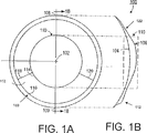
図1A及び1Bは、本発明の好ましい実施態様のコンタクトレンズ100を示す。コンタクトレンズ100は、前面106、後面104、頂部108及び底部109を含む。前面106は、オプチカルゾーン110、斜面付きリッジゾーン112、リッジオフゾーン122及びレンチキュラーゾーン150を有している。
1A and 1B show a
オプチカルゾーン110は、そこを通過する光を屈折させる。光線は、オプチカルゾーン110を通過すると、実焦点(遠視レンズの場合)又は虚焦点(近視レンズの場合)で合焦して、それによって鮮明な視覚を人に提供する。
The
斜面付きリッジゾーン112は、レンズのための垂直方向並進支持を提供する。斜面付きリッジゾーン112は、上縁114、下縁116、第一の側縁118及び第二の側縁120を有している。斜面付きリッジゾーン112はオプチカルゾーン110の下方に配置されている。リッジオフゾーン122は、オプチカルゾーン110、斜面付きリッジゾーン110の第一の側縁118及び斜面付きリッジゾーン110の第二の側縁120から外に延びている。リッジオフゾーン112は、レンズの回転安定性を増し、レンズ100の快適さを改善する。レンズ100はまた、さらなる快適さ及びより良好な角膜被覆のために、リッジオフゾーン160及び斜面付きリッジゾーン112の斜面付き下縁116から半径方向外側に延びる、狭い端部まで先細りするレンチキュラーゾーン150を含むことができる。
The
図4は、本発明のもう一つの好ましい実施態様のコンタクトレンズの正面図(前面)である。コンタクトレンズ100の前面106は、中心102、水平経線403、垂直経線405、オプチカルゾーン110、複合ゾーン420、周辺ゾーン430及び円形エッジゾーン440を有している。
FIG. 4 is a front view (front side) of a contact lens according to another preferred embodiment of the present invention. The
複合ゾーン420は、オプチカルゾーン110から外に周辺ゾーン430まで延びている。複合ゾーン420は、中央オプチカルゾーン110、複合ゾーン420及び周辺ゾーン430が互いに正接することを保証する面を有している。複合ゾーン420の面は、オプチカルゾーン110の外周縁から周辺ゾーン430の内周縁まで第一及び/又は第二導関数で連続している。複合ゾーン420の面は、好ましくは一以上のスプラインベースの数学的関数によって記述される。
The
周辺ゾーン430は、後面104と組み合わさって、(1)レンズ頂部から垂直経線及び垂直経線に平行な線それぞれに沿って下向きに累進的に増大して前面オプチカルゾーンとエッジゾーンとの間の位置で最大値に達したのち、エッジゾーンの縁まで減少するレンズ厚さを有すること、又は(2)垂直経線を横断する平面に関して鏡像対称性を有し、水平経線の周囲の領域で実質的に一定の厚さを有し、水平経線から垂直経線及び垂直経線に平行な線それぞれに沿ってコンタクトレンズの頂部又は底部まで累進的に減少する厚さを有することを特徴とする厚さプロフィールをレンズの周辺ゾーンに提供する面を有する。
The
周辺ゾーン430は、好ましくは一連の等値線を含み、これらの等値線に沿ってコンタクトレンズの厚さが実質的に一定である。等値線の一つは、中心102を水平に通過する水平経線103と合致し、残りの等値線は好ましくは弧である。中央の水平等値線よりも上にある弧それぞれは互いに異なり、所与の開眼位置での人の上まぶたの周縁の一つの弧を模す。中央の水平等値線よりも下にある弧それぞれは互いに異なり、所与の開眼位置での人の下まぶたの周縁の一つの弧を模す。
The
上下のまぶたが、完全もしくは部分的に開いた又は完全に閉じた眼の位置に依存して、異なる形状の弧(曲率半径)を有することができるということは当業者に周知である。眼が完全に閉じているとき、上まぶたの縁及び下まぶたの縁を表す両方の弧は直線状に閉じている。眼が完全に開いているとき、上まぶたの縁及び下まぶたの縁を表す両方の弧は急峻な曲率を有する。上まぶたの縁及び下まぶたの縁を表す両方の弧の曲率の間のこのような関係、すなわち等値線が水平経線に近づけば近づくほど等値線の曲率が平坦に近くなるという関係が、好ましくは、図4に示すような本発明のコンタクトレンズの設計に取り込まれる。 It is well known to those skilled in the art that the upper and lower eyelids can have differently shaped arcs (radius of curvature) depending on the position of the fully or partially open or fully closed eye. When the eye is fully closed, both arcs representing the upper and lower eyelid edges are closed in a straight line. When the eye is fully open, both arcs representing the edge of the upper eyelid and the edge of the lower eyelid have a steep curvature. Such a relationship between the curvatures of both arcs representing the upper eyelid edge and the lower eyelid edge, i.e., the closer the contour is to the horizontal meridian, the closer the curvature of the contour is to be flat. Preferably, it is incorporated into the design of the contact lens of the present invention as shown in FIG.
前面106の周辺ゾーン430は、好ましくは斜面付きリッジゾーンを含む。好ましくは、周辺ゾーンの厚さは、前面の頂部から垂直経線405及び垂直経線405に平行な線それぞれに沿って下向きに累進的に減少してオプチカルゾーンとエッジゾーンとの間の位置で最大値に達したのち、エッジゾーンの縁まで減少する。中央オプチカルゾーン110の外のレンズ厚さは、好ましくは、垂直経線405を通過する平面に関して鏡像対称性を有している。円形のエッジゾーン440は、周辺ゾーン430の外周縁から外に延びている。エッジゾーン440は、周辺ゾーンに正接し、後面と組み合わさって、眼の上への快適なレンズフィットを提供することができる実質的に均一な厚さを提供する。
The
図2は、式(1)によって記述される光学面を有するオプチカルゾーン200を示す。この表面はコマ収差様形状を有している。オプチカルゾーン200は、上寄り部分202及び下寄り部分204を有している。上寄り部分202は、遠見視力、たとえば近視及び遠視を矯正するための遠見度数を提供する。下寄り部分204は、老眼の人のための近見視力を矯正するための付加又は近見度数を提供する。
FIG. 2 shows an
オプチカルゾーンの度数は表面の第二導関数に比例する。したがって、図2に示すコマ収差様面を有するオプチカルゾーンは、図3に示す傾斜面と類似した光学度数プロフィールを有することができる。 The power of the optical zone is proportional to the second derivative of the surface. Therefore, the optical zone having the coma-like surface shown in FIG. 2 can have an optical power profile similar to the inclined surface shown in FIG.
図3は、オプチカルゾーン200の光学度数プロフィール300を示す。光学度数プロフィールは光学度数軸302に対して表されている。オプチカルゾーンの下寄り部分204は、より大きな光学度数を有し、それが領域304によって表されている。上寄り部分202は、より小さな光学度数を有し、それが領域306によって表されている。
FIG. 3 shows an
もう一つの態様で、本発明は、単独で、又は眼の光学系と組み合わさって、垂直方向コマ収差様波面収差を作り出すオプチカルゾーンを含むカスタマイズされた眼科用レンズを提供する。 In another aspect, the present invention provides a customized ophthalmic lens that includes an optical zone that produces vertical coma-like wavefront aberrations, either alone or in combination with an optical system of the eye.
本明細書で使用する「カスタマイズされた眼科用レンズ」とは、(1)個人の眼の収差計測値の入力を使用して設計されている眼科用レンズ及び/又は(2)個人の眼の角膜トポグラフィーを受け入れる面の一つを有する眼科用レンズをいう。 As used herein, a “customized ophthalmic lens” refers to (1) an ophthalmic lens that is designed using an input of an individual eye aberration measurement and / or (2) an individual eye eye. An ophthalmic lens having one of the surfaces that accepts corneal topography.
個人の眼の波面収差は、Shack-Hartmann技術、Tscherning技術、網膜光線追跡技術及び空間分解屈折計測技術をはじめとする当業者に公知の適当な方法によって測定することができる。たとえば、Liangらは、J. Optical Soc. Am. 11:1-9で、Hartmann-Shackシステムを使用して、異なる瞳孔直径で眼の波面収差を測定する方法を教示している。 The wavefront aberrations of an individual eye can be measured by any suitable method known to those skilled in the art including Shack-Hartmann technology, Tscherning technology, retinal ray tracing technology and spatially resolved refraction measurement technology. For example, Liang et al. In J. Optical Soc. Am. 11: 1-9 teach how to measure eye wavefront aberrations at different pupil diameters using the Hartmann-Shack system.
好ましくは、個人の眼の角膜トポグラフィーデータを使用して、カスタマイズされたコンタクトレンズの後面を、その眼の角膜トポグラフィー又は人口の一部分を統計的に表す角膜トポグラフィーを受け入れるように設計することができる。角膜トポグラフィーデータは、角膜トポグラファィー又はビデオケラトスコープを使用して取得することができる。角膜トポグラフィーデータは、眼科用レンズを設計する際の使用に適したいかなる形態にあってもよい。 Preferably, using the corneal topography data of the individual's eye, the rear surface of the customized contact lens is designed to accept a corneal topography that statistically represents a corneal topography of the eye or a portion of the population. Can do. Corneal topography data can be acquired using a corneal topography or a videokeratoscope. Corneal topography data can be in any form suitable for use in designing an ophthalmic lens.
典型的な形態としては、ゼルニケ多項式、点群データなどがあるが、これらに限定されない。好ましくは、角膜トポグラフィーデータは、眼の波面収差が定量化される形態にある。角膜トポグラフィーデータはまた、集団研究から導出された平均化角膜トポグラフィーであることもできる。このような平均化角膜トポグラフィーデータは、人口の一部分を表すことができ、カスタマイズされたコンタクトレンズの後面を設計するために使用することができる。 Typical forms include, but are not limited to, Zernike polynomials and point cloud data. Preferably, the corneal topography data is in a form in which eye wavefront aberrations are quantified. Corneal topography data can also be an averaged corneal topography derived from population studies. Such averaged corneal topography data can represent a portion of the population and can be used to design the back surface of a customized contact lens.
ある眼の角膜トポグラフィー又は人口の一部分を統計的に表す角膜トポグラフィーを受け入れることができる後面を有するコンタクトレンズは、その眼の角膜に対する良好又は十分なフィットを提供し、したがって、装用者の快適さを高める。コンタクトレンズの後面は眼の角膜トポグラフィーに完全に適合する必要はないと考えられている。完全な適合とは、コンタクトレンズの後面が角膜トポグラフィーにぴったり重畳可能であることを意味する。眼の角膜トポグラフィーに完全に適合する後面を有するコンタクトレンズは、眼の上でのレンズの動きが不十分であり、装用者の快適さに悪影響を及ぼすおそれがある。 A contact lens having a posterior surface capable of accepting a corneal topography of an eye or a corneal topography that statistically represents a portion of the population provides a good or sufficient fit to the cornea of the eye and is therefore comfortable for the wearer. Increase the height. It is believed that the posterior surface of the contact lens need not be fully compatible with the corneal topography of the eye. Perfect fit means that the rear surface of the contact lens can be closely superimposed on the corneal topography. Contact lenses having a posterior surface that perfectly conforms to the corneal topography of the eye may cause inadequate lens movement over the eye and adversely affect wearer comfort.
個人の眼の収差計測値に基づき、カスタマイズされたコンタクトレンズのオプチカルゾーンは多様な方法で設計されて、低次収差(デフォーカス、非点収差及びプリズム)を矯正するだけでなく、単独で、又は眼の光学系と組み合わさって、垂直方向コマ収差様波面収差を造る。 Based on individual eye aberration measurements, customized contact lens optical zones are designed in a variety of ways to not only correct low-order aberrations (defocus, astigmatism and prisms), but alone, Or, in combination with the optical system of the eye, a vertical coma-like wavefront aberration is created.
個人の眼が、垂直方向コマ収差様波面収差をはじめとする高次波面収差を有する場合、本発明の眼科用レンズは、垂直方向コマ収差様波面収差以外の波面収差を矯正又は最小限化するように設計することができる。場合によっては、垂直方向コマ収差様波面収差を眼科用レンズに導入して、眼科用レンズ+眼の垂直方向コマ収差様波面収差の全体量を増大させる。 When an individual's eye has higher-order wavefront aberrations including vertical coma-like wavefront aberrations, the ophthalmic lens of the present invention corrects or minimizes wavefront aberrations other than vertical coma-like wavefront aberrations. Can be designed as In some cases, vertical coma-like wavefront aberration is introduced into the ophthalmic lens to increase the overall amount of ophthalmic lens + eye vertical coma-like wavefront aberration.
個人の眼が一般に支配的な垂直方向コマ収差様波面収差を有さず、他の高次波面収差を有する場合、本発明の眼科用レンズは、垂直方向コマ収差様波面収差を得るために、支配的な高次波面収差それぞれの全部又は一部を矯正するように設計することができる。 If the individual's eye does not have a generally dominant vertical coma-like wavefront aberration, but has other higher-order wavefront aberrations, the ophthalmic lens of the present invention can obtain a vertical coma-like wavefront aberration. It can be designed to correct all or part of each dominant higher-order wavefront aberration.
本発明のカスタマイズされた眼科用レンズは、好ましくは、PCT特許出願公開公報WO02/088830に記載されている方法を使用して設計し、製造することができる。 The customized ophthalmic lens of the present invention can preferably be designed and manufactured using the methods described in PCT Patent Application Publication WO 02/0888830.
本発明の眼科用レンズ又はカスタマイズされた眼科用レンズは、公知の適当な光学設計システムを使用して設計することができる。光学モデルレンズを設計するための典型的な光学コンピュータ援用設計システムとしてはZEMAX(Focus Software社)があるが、これに限定されない。好ましくは、ZEMAX(Focus Software社)を使用して光学設計を実施する。光学モデルレンズの設計は、たとえば、機械的コンピュータ援用設計(CAD)システムにより、物理的レンズを製造するための機械的パラメータのセットに変換することができる。公知の適当な機械的CADシステムを本発明に使用することができる。光学モデルレンズの設計は、受け側のシステム、すなわち光学CAD又は機械的CADが所期の設計のNURBs(不均一有理Bスプライン)又はBeizier面を構成することを可能にする変換フォーマットを使用して、光学CADシステムと機械的CADシステムとの間で両方向に変換することができる。典型的な変換フォーマットとしては、VDA(verband der automobilindustrie)及びIGES(Initial Graphics Exchange Specification)があるが、これらに限定されない。このような変換フォーマットを使用することにより、レンズの全面を、半径方向非対称形状を有するレンズの製造を容易にする連続形状にすることができる。Beizier及びNURBs面は、多数のゾーンを複合し、解析し、最適化することができるため、オプチカルゾーン及び非光学ゾーンを含む複数のゾーンを有するレンズに特に有利である。より好ましくは、機械的CADシステムは、高次面を正確かつ数学的に表すことができる。このような機械的CADシステムの一例は、Parametric TechnologyのPro/Engineerである。光学モデルレンズの設計を機械的パラメータのセットに変換する場合には、一群の眼科用レンズに共通の特徴パラメータをレンズ設計過程で組み込むことができる。そのようなパラメータの例は、収縮、非光学エッジゾーン及びその曲率、中心厚さ、光学度数の範囲などを含む。 The ophthalmic lens or customized ophthalmic lens of the present invention can be designed using any suitable known optical design system. A typical optical computer aided design system for designing an optical model lens includes, but is not limited to ZEMAX (Focus Software). Preferably, optical design is performed using ZEMAX (Focus Software). The design of the optical model lens can be converted into a set of mechanical parameters for manufacturing a physical lens, for example, by a mechanical computer aided design (CAD) system. Any suitable mechanical CAD system known in the art can be used in the present invention. The design of the optical model lens uses the receiving system, ie a conversion format that allows optical CAD or mechanical CAD to construct NURBs (non-uniform rational B-splines) or Beizier surfaces of the intended design. It can be converted in both directions between an optical CAD system and a mechanical CAD system. Typical conversion formats include, but are not limited to, VDA (verband der automobilindustrie) and IGES (Initial Graphics Exchange Specification). By using such a conversion format, the entire surface of the lens can be made into a continuous shape that facilitates the production of a lens having a radially asymmetric shape. Beizier and NURBs surfaces are particularly advantageous for lenses having multiple zones, including optical and non-optical zones, because multiple zones can be combined, analyzed, and optimized. More preferably, the mechanical CAD system can accurately and mathematically represent higher order surfaces. An example of such a mechanical CAD system is Parametric Technology's Pro / Engineer. When converting an optical model lens design into a set of mechanical parameters, feature parameters common to a group of ophthalmic lenses can be incorporated in the lens design process. Examples of such parameters include shrinkage, non-optical edge zones and their curvature, center thickness, optical power range, and the like.
本発明の眼科用レンズは、たとえばコンピュータ制御可能な製造装置、成形などをはじめとする簡便な製造手段によって製造することができる。「コンピュータ制御可能な製造装置」とは、コンピュータシステムによって制御することができ、眼科用レンズを直接製造する、又は眼科用レンズを製造するための光学ツールを製造することができる装置をいう。公知の適当なコンピュータ制御可能な製造装置を本発明に使用することができる。典型的なコンピュータ制御可能な製造装置としては、旋盤、研磨機、成形設備及びレーザがあるが、これらに限定されない。好ましくは、コンピュータ制御可能な製造装置は、45°圧電カッタを有する2軸旋盤又は米国特許第6,122,999号でDurazo及びMorganによって開示されている旋盤装置又は数値制御式旋盤、たとえばPrecitech社の、Variform(登録商標)もしくはVarimax圧電セラミック高速ツールサーボアタッチメントを有するOptoform(登録商標)超精密旋盤(モデル30、40、50及び80)である。 The ophthalmic lens of the present invention can be manufactured by a simple manufacturing means such as a computer-controllable manufacturing apparatus or molding. “Computer-controllable manufacturing apparatus” refers to an apparatus that can be controlled by a computer system and that can directly manufacture an ophthalmic lens or an optical tool for manufacturing an ophthalmic lens. Any known suitable computer controllable manufacturing device can be used in the present invention. Typical computer controllable manufacturing equipment includes, but is not limited to, lathes, polishers, molding equipment and lasers. Preferably, the computer-controllable manufacturing device is a two-axis lathe with a 45 ° piezoelectric cutter or a lathe device or numerically controlled lathe disclosed by Durazo and Morgan in US Pat. No. 6,122,999, such as Precitech An Optoform® ultra-precision lathe (models 30, 40, 50 and 80) with a Variform® or Varimax piezoelectric ceramic high-speed tool servo attachment.
好ましくは、コンタクトレンズは、レンズが型で流し込み成形されるときコンタクトレンズ表面を模す成形面を含むコンタクトレンズ型から成形される。たとえば、数値制御式旋盤を備えた光学切削ツールを使用して、本発明のコンタクトレンズの前面の構造を取り入れた金属光学ツールを形成することができる。そして、そのツールを使用して前面型を製造したのち、それを後面型と関連させて、適当な液体レンズ形成材料を両型の間に使用し、次いでレンズ形成材料を圧縮し、硬化させることによって本発明のレンズを形成する。 Preferably, the contact lens is molded from a contact lens mold that includes a molding surface that mimics the surface of the contact lens when the lens is cast in the mold. For example, an optical cutting tool with a numerically controlled lathe can be used to form a metal optical tool incorporating the structure of the front surface of the contact lens of the present invention. The tool is then used to produce the front mold, then it is associated with the rear mold, an appropriate liquid lens forming material is used between the molds, and the lens forming material is then compressed and cured. To form the lens of the present invention.
好ましくは、本発明の眼科用レンズ又は同眼科用レンズを製造するために使用される光学ツールは、数値制御式旋盤、たとえばPrecitechの、Variform(登録商標)又はVarimax圧電セラミック高速ツールサーボアタッチメントを有するOptoform(登録商標)超精密旋盤(モデル30、40、50及び80)を使用して製造される。 Preferably, the ophthalmic lens or optical tool used to manufacture the ophthalmic lens of the present invention comprises a numerically controlled lathe, such as Precitech's Variform® or Varimax piezoelectric ceramic high-speed tool servo attachment. Manufactured using Optoform® ultra-precision lathes (models 30, 40, 50 and 80).
実例として、図1に示す斜面付きリッジゾーンを有するコンタクトレンズの製造を以下の工程で実施することができる。第一に、ユーザがパラメータのセット、たとえば表面許容差、同軸性許容差、レンズ設計の向き、ゼロ点を0、0に形成して前面及び後面それぞれに生成されるスポークの数、Z軸の向き及び形状に変換されるレンズ表面のタイプ(凹面又は凸面)を設定する。「表面許容差」とは、レンズ設計の表面上の理想位置からの投影点の許される位置逸脱をいう。逸脱は、レンズ設計の中心軸に対して平行又は垂直のいずれの方向であることもできる。「同軸性許容差」とは、所与の弧からのある点の許される逸脱をいう。「スポーク」とは、中心軸から外に放射状に延び、中心軸に対して垂直である光線をいう。「半直径スポーク」とは、レンズ設計の中心軸からエッジまでの線分をいう。「等間隔の半直径スポーク」とは、すべての半直径スポークが中心軸から外に放射状に延び、一つの等しい角度だけ互いに離れていることをいう。「点間隔」とは、半直径スポーク沿いの二つの点の間の距離をいう。 Illustratively, a contact lens having a beveled ridge zone as shown in FIG. 1 can be manufactured in the following steps. First, the user sets a parameter, for example, surface tolerance, coaxial tolerance, lens design orientation, number of spokes generated on the front and rear surfaces by forming zero points at 0, 0, Sets the type (concave or convex) of the lens surface that is converted into orientation and shape. “Surface tolerance” refers to the allowed deviation of the projected point from the ideal position on the surface of the lens design. The deviation can be either parallel or perpendicular to the central axis of the lens design. “Coaxiality tolerance” refers to the allowed deviation of a point from a given arc. “Spokes” refer to light rays that extend radially outward from a central axis and are perpendicular to the central axis. “Half-diameter spoke” refers to the line segment from the central axis of the lens design to the edge. “Equally spaced half-diameter spokes” means that all half-diameter spokes extend radially outward from the central axis and are separated from each other by one equal angle. “Point spacing” refers to the distance between two points along a half-diameter spoke.
第二に、ユーザが、中心軸に対して平行な方向で多数の等間隔の半直径スポークそれぞれに沿ってレンズ設計の表面(たとえば前面)に投影する点の数を決定する。前面の二つの突起の一方が位置する方位角にある半直径スポークを半直径プロービングスポークとして選択する。等間隔の点を、点の各対が10ミクロンの点間隔によって分けられる半直径プロービングスポークに沿って投影する。次に、投影した点すべてを、それぞれが3個の連続する点、すなわち第一の点、中間点及び第三の点で構成される一連の群に分割する。各点は、一つの群又は二つの群に属することができる。一度に一群ずつ、中間点と、対応する群の第一の点及び第三の点を連結する線との距離を所定の表面許容差と比較することにより、中心軸からエッジまで又はエッジから中心軸まで、群の中間点の表面の曲率を解析する。中間点と、群の第一の点及び第三の点を連結する線との距離が所定の表面許容差よりも大きいならば、その点での表面の曲率は鋭く、その群の第一の点と中間点との間にさらなる点を投影する。第一の点とさらなる点との間の点間隔は、さらなる点と中間点との間の点間隔に等しい。さらなる点を追加したのち、新たに追加された点を含むすべての点を再分類し、一連の群それぞれの中間点における表面の曲率を解析する。一連群それぞれの中間点と、対応する群の第一及び第三の点をプロービングスポークに沿って連結する線との距離が所定の表面許容差以下になるまで、このような反復手順を繰り返す。このようにして、所望の数の等間隔の半直径スポークそれぞれに沿ってレンズ設計の表面に投影される点の数及び隣接する点の一連の対の点間隔を決定する。 Second, the user determines the number of points to project onto the surface (eg, the front surface) of the lens design along each of a number of equally spaced half-diameter spokes in a direction parallel to the central axis. A half-diameter spoke at an azimuth angle where one of the two front protrusions is located is selected as the half-diameter probing spoke. Equally spaced points are projected along half-diameter probing spokes where each pair of points is separated by a 10 micron point spacing. Next, all the projected points are divided into a series of groups each consisting of three consecutive points, a first point, an intermediate point, and a third point. Each point can belong to one group or two groups. One group at a time, center-to-edge or center-to-edge by comparing the distance between the midpoint and the line connecting the first and third points of the corresponding group with a given surface tolerance To the axis, analyze the curvature of the surface of the midpoint of the group. If the distance between the midpoint and the line connecting the first point and the third point of the group is greater than a predetermined surface tolerance, the curvature of the surface at that point is sharp and the first point of the group Project additional points between points and midpoints. The point spacing between the first point and the further point is equal to the point spacing between the further point and the intermediate point. After adding more points, all points including the newly added point are reclassified and the curvature of the surface at the midpoint of each of the series is analyzed. Such an iterative procedure is repeated until the distance between the midpoint of each series and the line connecting the first and third points of the corresponding group along the probing spoke is less than or equal to a predetermined surface tolerance. In this way, the number of points projected onto the surface of the lens design along each desired number of equally spaced half-diameter spokes and the point spacing of a series of pairs of adjacent points are determined.
次に、上記のように決定した数の点を、24、96又は384個の半直径スポークそれぞれに沿ってレンズ設計の前面に投影する。半直径スポークそれぞれに関して、第一導関数で連続的である半経線を生成する。半経線は、一連の弧及び場合によっては直線を含み、各弧は、少なくとも3個の連続する点を所望の同軸性許容差内で球面数学的関数に当てはめることによって画定される。各直線は、少なくとも3個の連続する点を接続することによって得られる。好ましくは、中心軸からエッジまでの弧当てはめルーチンを開始する。同様に、上記手順にしたがって、レンズ設計の後面の形状への変換を実施することができる。 The number of points determined as above is then projected onto the front surface of the lens design along each of 24, 96 or 384 half-diameter spokes. For each half-diameter spoke, generate a semi-meridian that is continuous with the first derivative. A semi-meridian includes a series of arcs and possibly straight lines, each arc defined by fitting at least three consecutive points to a spherical mathematical function within a desired coaxial tolerance. Each straight line is obtained by connecting at least three consecutive points. Preferably, an arc fitting routine from the central axis to the edge is started. Similarly, conversion to the shape of the rear surface of the lens design can be performed according to the above procedure.
レンズ設計を、製造システムで製造されるコンタクトレンズの形状に変換したのち、ヘッダの情報及びレンズの形状に関する情報を含むミニファイルを作成する。このミニファイルはまた、半径方向位置それぞれにおける他の経線それぞれの平均高さに基づき、その振動計算を基づかせることができるゼロ位置をVariformに与えるゼロ半経線を含む。このミニファイルで、すべての半経線は同じ数のゾーンを有する。これは、すべての経線に関してゾーンの数を均等化するための回数だけ半経線の最後のゾーンをコピーすることによって達成される。ミニファイルが完成したのち、それを、Variform(登録商標)圧電セラミック高速ツールサーボアタッチメントを有するOptoform(登録商標)超精密旋盤(モデル30、40、50又は80)にロードし、実行して本発明のコンタクトレンズを製造する。 After the lens design is converted into the shape of a contact lens manufactured by the manufacturing system, a mini-file including header information and information regarding the lens shape is created. The minifile also includes a zero semi-meridian that gives Variform a zero position based on the average height of each of the other meridians at each radial position, on which its vibration calculations can be based. In this minifile, all semi-meridians have the same number of zones. This is accomplished by copying the last zone of the semi-meridian number of times to equalize the number of zones for all meridians. After the minifile is completed, it is loaded into an Optoform® ultra-precision lathe (model 30, 40, 50 or 80) with Variform® piezoelectric ceramic high-speed tool servo attachment and executed to execute the present invention. Manufacture contact lenses.
本発明は、さらなる態様で、本発明の眼科用レンズを製造する方法を提供する。方法は、眼科用レンズを製造手段によって製造する工程を含み、この眼科用レンズがオプチカルゾーンを含み、このオプチカルゾーンが、第一の面及び反対側の第二の面を有し、眼科用レンズの頂部から底部まで垂直方向にあるコマ収差様波面収差を含むものである。垂直方向コマ収差様波面収差は、老眼を最小限化/矯正するために、又は正視化過程を妨害する、眼の調節機能が受けるストレスを軽減する(たとえば近視予防レンズの場合)ために導入される。 The present invention provides, in a further aspect, a method for producing the ophthalmic lens of the present invention. The method includes the step of manufacturing an ophthalmic lens by a manufacturing means, the ophthalmic lens including an optical zone, the optical zone having a first surface and an opposite second surface, the ophthalmic lens Including a coma-like wavefront aberration in the vertical direction from the top to the bottom. Vertical coma-like wavefront aberrations are introduced to minimize / correct presbyopia or to reduce the stress experienced by the eye accommodation function that interferes with the normalization process (eg in the case of myopia prevention lenses). The
本発明の眼科用レンズは、公知の適当な光学度量衡システムを特徴とすることができる。レンズの垂直方向コマ収差様収差及び他の波面収差は、Shack-Hartmann技術、Tschering技術、網膜光線追跡技術及び空間分解屈折計測技術をはじめとする当業者に公知の適当な方法によって測定することができる。 The ophthalmic lens of the present invention can be characterized by a known suitable optical metrology system. Lens vertical coma-like aberrations and other wavefront aberrations can be measured by appropriate methods known to those skilled in the art including Shack-Hartmann technology, Tschering technology, retinal ray tracing technology and spatially resolved refraction measurement technology. it can.
本発明は、なおさらなる態様で、老眼を矯正又は最小限化する方法を提供する。本発明の方法は、角膜を再形成して垂直方向コマ収差様波面収差を作り出す工程を含む。 The present invention, in a still further aspect, provides a method for correcting or minimizing presbyopia. The method of the present invention includes the step of reshaping the cornea to create a vertical coma-like wavefront aberration.
角膜の形状は、種々の方法によって改変することができる。本発明による一つの方法は、角膜の光学面に対するレーザビームのエネルギー分布を制御する方法である。本発明によるもう一つの方法は、角膜の光学面に対するフライングスポットレーザパターンを制御する方法である。本発明によるさらに別の方法は、角膜の光学面に対する切除角を制御する方法である。本発明によるさらに別の方法は、数学モデルにしたがって角膜を切除する方法である。 The shape of the cornea can be modified by various methods. One method according to the present invention is a method for controlling the energy distribution of a laser beam relative to the optical surface of the cornea. Another method according to the present invention is a method for controlling a flying spot laser pattern relative to the optical surface of the cornea. Yet another method according to the invention is a method for controlling the ablation angle of the cornea with respect to the optical surface. Yet another method according to the present invention is a method of excising the cornea according to a mathematical model.
上記実施態様は、例示のためのだけに記載したものである。本発明を逸することなく、本明細書で開示した具体的な実施態様に多くの変更を加えることができることが容易に理解されよう。したがって、本発明の範囲は、具体的に記載した上記実施態様に限定されるのではなく、請求の範囲によって決定される。 The above embodiments have been described by way of example only. It will be readily appreciated that many modifications can be made to the specific embodiments disclosed herein without departing from the invention. Accordingly, the scope of the invention is not limited to the specific embodiments described above, but is determined by the claims.
Claims (25)
コマ収差様波面収差が、OSA(Optical Society of America)規格案ゼルニケ多項式の三次、五次、七次ゼルニケコマ収差様項及びそれらの組み合わせのいずれかによって記述される波面収差又はその等価物である波面収差であり、
オプチカルゾーンの第一の面及び第二の面の少なくとも一方が、双円錐数学的関数と少なくとも一つの垂直方向コマ収差様ゼルニケ項又はその等価物との組み合わせによって表わされ、
オプチカルゾーンの第一の面及び第二の面の少なくとも一方が非対称であり、オプチカルゾーンが、オプチカルゾーンの頂部から底部まで増大して行く光学度数を有する、眼科用レンズ。An ophthalmic lens comprising an optical zone, the optical zone having a first surface and an opposite second surface, and including a vertical coma-like wavefront aberration;
A wavefront in which the coma-like wavefront aberration is a wavefront aberration described by any of the third-order, fifth-order, seventh-order Zernike coma aberration-like terms of an OSA (Optical Society of America) standard draft Zernike polynomial, or a combination thereof, or an equivalent thereof aberration der is,
At least one of the first and second surfaces of the optical zone is represented by a combination of a bicone mathematical function and at least one vertical coma-like Zernike term or equivalent thereof;
An ophthalmic lens , wherein at least one of the first and second surfaces of the optical zone is asymmetric and the optical zone has an optical power that increases from the top to the bottom of the optical zone .
Z(ρ、θ)は、オプチカルゾーンを記述し、
cxは、x′方向における曲率(半径の逆数)であり、
cyは、y′方向における曲率(半径の逆数)であり、
k x は、x′方向における円錐定数であり、
kyは、y′方向における円錐定数であり、
rは、少なくとも一方の面の半径に等しく、
ρは、正規化瞳孔座標(r/rmax)に等しく、
θは、角成分であり、
Z7は、RMS μm単位の垂直コマ収差の係数である)
によって表わされる、請求項1記載の眼科用レンズ。The at least one vertical coma aberration-like Zernike term is a vertical third-order coma aberration-like Zernike term Z7 (based on the OSA draft Zernike polynomial), and at least one of the first surface and the second surface of the optical zone is , The following formula
Z (ρ, θ) describes the optical zone,
c x is the curvature in the x ′ direction (the reciprocal of the radius),
c y is the curvature in the y ′ direction (the reciprocal of the radius);
k x is the conic constant in the x ′ direction,
k y is the conic constant in the y ′ direction,
r is equal to the radius of at least one surface;
ρ is equal to the normalized pupil coordinates (r / rmax),
θ is an angular component,
Z7 is a coefficient of vertical coma in RMS μm)
Ophthalmic lenses that are, according to claim 1, wherein represented by.
後面と、
垂直経線、水平経線、前面オプチカルゾーン、前面オプチカルゾーンから外に延びる複合ゾーン、複合ゾーンを包囲する周辺ゾーン及び周辺ゾーンに外接し、正接するエッジゾーンを含む反対側の前面と
を含み、
前面オプチカルゾーンが、オプチカルゾーンの第一の面及び第二の面の一方であり、複合ゾーンが、周辺ゾーン、複合ゾーン及び前面オプチカルゾーンが互いに正接することを保証する面を有し、周辺ゾーンが、後面と組み合わさって、(1)レンズの頂部から垂直経線及び垂直経線に平行な線それぞれに沿って下向きに累進的に増大して前面オプチカルゾーンとエッジゾーンとの間の位置で最大値に達したのち、エッジゾーンの縁まで減少するレンズ厚さを有すること、又は(2)垂直経線を横断する平面に関して鏡像対称性を有し、水平経線の周囲の領域で実質的に一定の厚さを有し、水平経線から垂直経線及び垂直経線に平行な線それぞれに沿ってコンタクトレンズの頂部又は底部まで累進的に減少する厚さを有することを特徴とする厚さプロフィールをレンズの周辺ゾーンに提供する面を有する、請求項8記載の眼科用レンズ。Contact lenses
On the back,
A vertical meridian, a horizontal meridian, a front optical zone, a composite zone extending out from the front optical zone, a peripheral zone surrounding the composite zone, and a front surface on the opposite side including an edge zone circumscribing and tangent to the peripheral zone;
The front optical zone is one of the first side and the second side of the optical zone, and the composite zone has a surface that ensures that the peripheral zone, the composite zone and the front optical zone are tangent to each other; In combination with the rear surface, (1) a maximum value at a position between the front optical zone and the edge zone that progressively increases downward from the top of the lens along each of the vertical meridians and parallel to the vertical meridians. Having a lens thickness that decreases to the edge of the edge zone, or (2) having a mirror image symmetry with respect to a plane transverse to the vertical meridian and having a substantially constant thickness in the region around the horizontal meridian Having a thickness that progressively decreases from the horizontal meridian to the top or bottom of the contact lens along each of the vertical meridian and a line parallel to the vertical meridian It is having a surface to provide a profile to the peripheral zone of a lens, the ophthalmic lens according to claim 8.
コマ収差様波面収差が、OSA(Optical Society of America)規格案ゼルニケ多項式の三次、五次、七次ゼルニケコマ収差様項及びそれらの組み合わせのいずれかによって記述される波面収差又はその等価物である波面収差であり、
オプチカルゾーンの第一の面及び第二の面の少なくとも一方が、双円錐数学的関数と少なくとも一つの垂直方向コマ収差様ゼルニケ項又はその等価物との組み合わせによって表わされ、
オプチカルゾーンの第一の面及び第二の面の少なくとも一方が非対称であり、オプチカルゾーンが、オプチカルゾーンの頂部から底部まで増大して行く光学度数を有する、カスタマイズされた眼科用レンズ。Including an optical zone that produces vertical coma-like wavefront aberrations, alone or in combination with the optical system of the eye,
A wavefront in which the coma-like wavefront aberration is a wavefront aberration described by any of the third-order, fifth-order, seventh-order Zernike coma aberration-like terms of an OSA (Optical Society of America) standard draft Zernike polynomial, or a combination thereof, or an equivalent thereof aberration der is,
At least one of the first and second surfaces of the optical zone is represented by a combination of a bicone mathematical function and at least one vertical coma-like Zernike term or equivalent thereof;
A customized ophthalmic lens , wherein at least one of the first and second surfaces of the optical zone is asymmetric and the optical zone has an optical power that increases from the top to the bottom of the optical zone .
コマ収差様波面収差が、OSA(Optical Society of America)規格案ゼルニケ多項式の三次、五次、七次ゼルニケコマ収差様項及びそれらの組み合わせのいずれかによって記述される波面収差又はその等価物である波面収差であり、
オプチカルゾーンの第一の面及び第二の面の少なくとも一方が、双円錐数学的関数と少なくとも一つの垂直方向コマ収差様ゼルニケ項又はその等価物との組み合わせによって表わされ、
オプチカルゾーンの第一の面及び第二の面の少なくとも一方が非対称であり、オプチカルゾーンが、オプチカルゾーンの頂部から底部まで増大して行く光学度数を有する、方法。A method of manufacturing an ophthalmic lens comprising the steps of manufacturing an ophthalmic lens by a manufacturing means, wherein the ophthalmic lens includes an optical zone, the optical zone including a first surface and an opposite second surface. And including vertical coma-like wavefront aberration,
A wavefront in which the coma-like wavefront aberration is a wavefront aberration described by any of the third-order, fifth-order, seventh-order Zernike coma aberration-like terms of an OSA (Optical Society of America) standard draft Zernike polynomial, or a combination thereof, or an equivalent thereof aberration der is,
At least one of the first and second surfaces of the optical zone is represented by a combination of a bicone mathematical function and at least one vertical coma-like Zernike term or equivalent thereof;
A method wherein at least one of the first and second surfaces of the optical zone is asymmetric and the optical zone has an optical power that increases from the top to the bottom of the optical zone .
Applications Claiming Priority (3)
| Application Number | Priority Date | Filing Date | Title |
|---|---|---|---|
| US44340003P | 2003-01-29 | 2003-01-29 | |
| US60/443,400 | 2003-01-29 | ||
| PCT/EP2004/000738 WO2004068214A1 (en) | 2003-01-29 | 2004-01-28 | Opththalmic lenses |
Related Child Applications (1)
| Application Number | Title | Priority Date | Filing Date |
|---|---|---|---|
| JP2012200545A Division JP5689859B2 (en) | 2003-01-29 | 2012-09-12 | Ophthalmic lens |
Publications (3)
| Publication Number | Publication Date |
|---|---|
| JP2006515938A JP2006515938A (en) | 2006-06-08 |
| JP2006515938A5 JP2006515938A5 (en) | 2007-03-15 |
| JP5111850B2 true JP5111850B2 (en) | 2013-01-09 |
Family
ID=32825324
Family Applications (2)
| Application Number | Title | Priority Date | Filing Date |
|---|---|---|---|
| JP2006501637A Expired - Fee Related JP5111850B2 (en) | 2003-01-29 | 2004-01-28 | Ophthalmic lens |
| JP2012200545A Expired - Fee Related JP5689859B2 (en) | 2003-01-29 | 2012-09-12 | Ophthalmic lens |
Family Applications After (1)
| Application Number | Title | Priority Date | Filing Date |
|---|---|---|---|
| JP2012200545A Expired - Fee Related JP5689859B2 (en) | 2003-01-29 | 2012-09-12 | Ophthalmic lens |
Country Status (6)
| Country | Link |
|---|---|
| US (1) | US7036931B2 (en) |
| EP (1) | EP1590703B1 (en) |
| JP (2) | JP5111850B2 (en) |
| AT (1) | ATE540332T1 (en) |
| CA (1) | CA2509770C (en) |
| WO (1) | WO2004068214A1 (en) |
Cited By (1)
| Publication number | Priority date | Publication date | Assignee | Title |
|---|---|---|---|---|
| JP2013037373A (en) * | 2003-01-29 | 2013-02-21 | Novartis Ag | Ophthalmic lens |
Families Citing this family (129)
| Publication number | Priority date | Publication date | Assignee | Title |
|---|---|---|---|---|
| US7628485B2 (en) * | 2000-03-31 | 2009-12-08 | Coopervision International Holding Company, Lp | Contact lens having a uniform horizontal thickness profile |
| US6467903B1 (en) * | 2000-03-31 | 2002-10-22 | Ocular Sciences, Inc. | Contact lens having a uniform horizontal thickness profile |
| US7152975B2 (en) * | 2000-11-10 | 2006-12-26 | Cooper Vision, Inc. | Junctionless ophthalmic lenses and methods for making same |
| US20070142912A1 (en) * | 2001-01-30 | 2007-06-21 | Willis Timothy R | Refractive intraocular implant lens and method |
| US8486140B2 (en) * | 2001-01-30 | 2013-07-16 | Timothy R. Willis | Refractive intraocular implant lens and method |
| JP4485360B2 (en) * | 2002-08-06 | 2010-06-23 | ノバルティス アーゲー | contact lens |
| US6939005B2 (en) | 2003-08-20 | 2005-09-06 | Johnson & Johnson Vision Care Inc. | Rotationally stabilized contact lenses |
| US20050041203A1 (en) * | 2003-08-20 | 2005-02-24 | Lindacher Joseph Michael | Ophthalmic lens with optimal power profile |
| US7036930B2 (en) | 2003-10-27 | 2006-05-02 | Johnson & Johnson Vision Care, Inc. | Methods for reducing corneal staining in contact lens wearers |
| US20050104240A1 (en) | 2003-11-14 | 2005-05-19 | Jethmalani Jagdish M. | Method of manufacturing an optical lens |
| US7201480B2 (en) | 2004-05-20 | 2007-04-10 | Johnson & Johnson Vision Care, Inc. | Methods for rotationally stabilizing contact lenses |
| GB2430047B (en) * | 2004-07-01 | 2009-01-28 | Auckland Uniservices Ltd | Method of manufacturing a contact lens system for correcting myopic vision |
| US7506983B2 (en) | 2004-09-30 | 2009-03-24 | The Hong Kong Polytechnic University | Method of optical treatment |
| SE0402769D0 (en) | 2004-11-12 | 2004-11-12 | Amo Groningen Bv | Method of selecting intraocular lenses |
| ITTO20040825A1 (en) * | 2004-11-23 | 2005-02-23 | Cogliati Alvaro | ARTIFICIAL LENSES IN PARTICULAR CONTACT LENSES OR INTRA-OCULAR LENSES FOR THE CORRECTION OF THE PRESBYOPIA EVENTUALLY ASSOCIATED WITH OTHER VISUAL DEFECTS, AND THEIR MANUFACTURING METHOD |
| ATE395883T1 (en) * | 2005-04-05 | 2008-06-15 | Alcon Inc | INTRAOCULAR LENS |
| US7261412B2 (en) | 2005-06-30 | 2007-08-28 | Visx, Incorporated | Presbyopia correction through negative high-order spherical aberration |
| US8801781B2 (en) * | 2005-10-26 | 2014-08-12 | Abbott Medical Optics Inc. | Intraocular lens for correcting corneal coma |
| FR2894038B1 (en) | 2005-11-29 | 2008-03-07 | Essilor Int | OPHTHALMIC LENS. |
| DE102006026524A1 (en) * | 2006-06-06 | 2007-12-13 | Satisloh Ag | Machine for processing optical workpieces, in particular plastic spectacle lenses |
| US20080004698A1 (en) * | 2006-06-30 | 2008-01-03 | Alcon, Inc. | Correction of surgically-induced astigmatism during intraocular lens implants |
| FR2906621B1 (en) * | 2006-09-28 | 2008-11-28 | Essilor Int | METHOD FOR DETERMINING AN OPHTHALMIC LENS |
| CN101523271B (en) * | 2006-10-10 | 2012-07-04 | 诺瓦提斯公司 | Lens with optically controlled peripheral portion and method of designing and manufacturing same |
| WO2008111856A1 (en) | 2007-03-09 | 2008-09-18 | Auckland Uniservices Limited | Contact lens and method |
| CA2695516C (en) * | 2007-08-07 | 2016-02-16 | Novartis Ag | Toric contact lens with improved posterior surface design |
| US9216080B2 (en) * | 2007-08-27 | 2015-12-22 | Amo Groningen B.V. | Toric lens with decreased sensitivity to cylinder power and rotation and method of using the same |
| US8974526B2 (en) | 2007-08-27 | 2015-03-10 | Amo Groningen B.V. | Multizonal lens with extended depth of focus |
| US8740978B2 (en) * | 2007-08-27 | 2014-06-03 | Amo Regional Holdings | Intraocular lens having extended depth of focus |
| US20090062911A1 (en) * | 2007-08-27 | 2009-03-05 | Amo Groningen Bv | Multizonal lens with extended depth of focus |
| US8747466B2 (en) * | 2007-08-27 | 2014-06-10 | Amo Groningen, B.V. | Intraocular lens having extended depth of focus |
| ES2565244T3 (en) | 2007-10-05 | 2016-04-01 | Essilor International (Compagnie Générale d'Optique) | A method to provide an ophthalmic lens for glasses by calculating or selecting a design |
| GB2453993A (en) * | 2007-10-25 | 2009-04-29 | Contact Lens Prec Lab Ltd | Soft contact lens for correcting abnormal corneal topography |
| US8057034B2 (en) | 2007-10-26 | 2011-11-15 | Brien Holden Vision Institute | Methods and apparatuses for enhancing peripheral vision |
| DK2211747T3 (en) * | 2007-10-29 | 2019-07-22 | Junzhong Liang | Devices for refractive presbyopia treatment |
| WO2009076500A1 (en) * | 2007-12-11 | 2009-06-18 | Bausch & Lomb Incorporated | Method and apparatus for providing eye optical systems with extended depths of field |
| US9724190B2 (en) | 2007-12-13 | 2017-08-08 | Amo Groningen B.V. | Customized multifocal ophthalmic lens |
| WO2009101202A1 (en) | 2008-02-15 | 2009-08-20 | Amo Regional Holdings | System, ophthalmic lens, and method for extending depth of focus |
| US8439498B2 (en) | 2008-02-21 | 2013-05-14 | Abbott Medical Optics Inc. | Toric intraocular lens with modified power characteristics |
| US8646908B2 (en) | 2008-03-04 | 2014-02-11 | Johnson & Johnson Vision Care, Inc. | Rotationally stabilized contact lenses and methods for their design |
| US20110029073A1 (en) | 2008-04-02 | 2011-02-03 | Junzhong Liang | Methods and Devices for Refractive Corrections of Presbyopia |
| WO2010064150A2 (en) * | 2008-04-04 | 2010-06-10 | Amo Regional Holdings | Systems and methods for determing intraocular lens power |
| CA2719421A1 (en) | 2008-04-18 | 2009-10-22 | Novartis Ag | Myopia control means |
| US7871162B2 (en) * | 2008-04-24 | 2011-01-18 | Amo Groningen B.V. | Diffractive multifocal lens having radially varying light distribution |
| US8231219B2 (en) * | 2008-04-24 | 2012-07-31 | Amo Groningen B.V. | Diffractive lens exhibiting enhanced optical performance |
| US8480228B2 (en) | 2009-12-18 | 2013-07-09 | Amo Groningen B.V. | Limited echelette lens, systems and methods |
| US8862447B2 (en) | 2010-04-30 | 2014-10-14 | Amo Groningen B.V. | Apparatus, system and method for predictive modeling to design, evaluate and optimize ophthalmic lenses |
| JP5866696B2 (en) * | 2008-08-11 | 2016-02-17 | ノバルティス アーゲー | Lens and manufacturing method thereof |
| AU2013231016B2 (en) * | 2008-08-11 | 2015-07-16 | Alcon Inc. | A Lens Design and Method for Preventing or Slowing the Progression of Myopia |
| DE102009053467B4 (en) | 2008-11-14 | 2018-01-18 | Rodenstock Gmbh | Ophthalmic lens with peripheral power variation |
| US8685087B2 (en) | 2008-12-11 | 2014-04-01 | Bausch & Lomb Incorporated | Intraocular lens and method of making an intraocular lens |
| WO2010080413A1 (en) * | 2008-12-19 | 2010-07-15 | Novartis Ag | Correction of peripheral defocus of an eye and control of refractive error development |
| US8960901B2 (en) | 2009-02-02 | 2015-02-24 | Johnson & Johnson Vision Care, Inc. | Myopia control ophthalmic lenses |
| US8331048B1 (en) | 2009-12-18 | 2012-12-11 | Bausch & Lomb Incorporated | Methods of designing lenses having selected depths of field |
| JP2013518301A (en) * | 2010-01-22 | 2013-05-20 | オークリー インコーポレイテッド | Lens for 3D eyewear |
| JP5657266B2 (en) * | 2010-04-14 | 2015-01-21 | 株式会社メニコン | Contact lenses for correcting irregular astigmatism |
| SG186700A1 (en) * | 2010-06-01 | 2013-02-28 | Elenza Inc | Implantable ophthalmic device with an aspheric lens |
| US9220590B2 (en) | 2010-06-10 | 2015-12-29 | Z Lens, Llc | Accommodative intraocular lens and method of improving accommodation |
| AU2011336183B2 (en) | 2010-12-01 | 2015-07-16 | Amo Groningen B.V. | A multifocal lens having an optical add power progression, and a system and method of providing same |
| US8894204B2 (en) | 2010-12-17 | 2014-11-25 | Abbott Medical Optics Inc. | Ophthalmic lens, systems and methods having at least one rotationally asymmetric diffractive structure |
| US9931200B2 (en) | 2010-12-17 | 2018-04-03 | Amo Groningen B.V. | Ophthalmic devices, systems, and methods for optimizing peripheral vision |
| JP2014515503A (en) * | 2011-06-01 | 2014-06-30 | ボーシュ アンド ローム インコーポレイティド | Contact lens with hybrid orientation features |
| EP2765901A1 (en) | 2011-10-14 | 2014-08-20 | Amo Groningen B.V. | Apparatus, system and method to account for spherical aberration at the iris plane in the design of an intraocular lens |
| US9360683B2 (en) | 2012-01-31 | 2016-06-07 | Carl Zeiss Meditec Ag | Anti myopia lens |
| TWI588560B (en) | 2012-04-05 | 2017-06-21 | 布萊恩荷登視覺協會 | Lens, device, method and system for refractive error |
| US9554889B2 (en) | 2012-05-07 | 2017-01-31 | Boston Foundation For Sight | Customized wavefront-guided methods, systems, and devices to correct higher-order aberrations |
| US9364318B2 (en) | 2012-05-10 | 2016-06-14 | Z Lens, Llc | Accommodative-disaccommodative intraocular lens |
| EP2860507B1 (en) * | 2012-05-11 | 2017-04-19 | Menicon Co., Ltd. | Lens power measurement device and measurement method |
| BR112015004617A2 (en) | 2012-08-31 | 2017-07-04 | Amo Groningen Bv | systems and methods for extended multi-lens lens extended focus depth |
| US9201250B2 (en) | 2012-10-17 | 2015-12-01 | Brien Holden Vision Institute | Lenses, devices, methods and systems for refractive error |
| HK1212194A1 (en) | 2012-10-17 | 2016-06-10 | Brien Holden Vision Institute | Lenses, devices, methods and systems for refractive error |
| AU2013353764B2 (en) | 2012-12-04 | 2018-12-06 | Amo Groningen B.V. | Lenses systems and methods for providing binocular customized treatments to correct presbyopia |
| AU2013200761A1 (en) * | 2013-02-13 | 2014-08-28 | Brien Holden Vision Institute | Contact lens stabilisation |
| EP2965145A2 (en) * | 2013-03-07 | 2016-01-13 | Amo Groningen B.V. | Lens providing extended depth of focus and method relating to same |
| US9561098B2 (en) | 2013-03-11 | 2017-02-07 | Abbott Medical Optics Inc. | Intraocular lens that matches an image surface to a retinal shape, and method of designing same |
| US10216004B2 (en) | 2013-04-29 | 2019-02-26 | Essilor International | System for providing an opthalmic lens |
| JP6291723B2 (en) * | 2013-05-14 | 2018-03-14 | 株式会社ニコン | Progressive power lens and generation method of progressive power surface of progressive power lens |
| CA2942200C (en) | 2014-03-10 | 2023-08-15 | Amo Groningen B.V. | Piggyback intraocular lens that improves overall vision where there is a local loss of retinal function |
| WO2016142736A1 (en) * | 2015-03-10 | 2016-09-15 | Amo Groningen B.V. | Fresnel piggyback intraocular lens that improves overall vision where there is a local loss of retinal function |
| CA2946356C (en) | 2014-04-21 | 2022-09-20 | Amo Groningen B.V. | Ophthalmic devices, system and methods that improve peripheral vision |
| EP3171213B1 (en) * | 2014-07-15 | 2023-11-22 | Menicon Co., Ltd. | Contact lens manufacturing method and contact lens |
| US12127934B2 (en) | 2014-09-09 | 2024-10-29 | Staar Surgical Company | Method of Providing Modified Monovision to a Subject with a First Lens and a Second Lens |
| US10881504B2 (en) | 2016-03-09 | 2021-01-05 | Staar Surgical Company | Ophthalmic implants with extended depth of field and enhanced distance visual acuity |
| US10485655B2 (en) | 2014-09-09 | 2019-11-26 | Staar Surgical Company | Ophthalmic implants with extended depth of field and enhanced distance visual acuity |
| US10159562B2 (en) | 2014-09-22 | 2018-12-25 | Kevin J. Cady | Intraocular pseudophakic contact lenses and related systems and methods |
| US11109957B2 (en) | 2014-09-22 | 2021-09-07 | Onpoint Vision, Inc. | Intraocular pseudophakic contact lens with mechanism for securing by anterior leaflet of capsular wall and related system and method |
| US11938018B2 (en) | 2014-09-22 | 2024-03-26 | Onpoint Vision, Inc. | Intraocular pseudophakic contact lens (IOPCL) for treating age-related macular degeneration (AMD) or other eye disorders |
| US10945832B2 (en) | 2014-09-22 | 2021-03-16 | Onpoint Vision, Inc. | Intraocular pseudophakic contact lens with mechanism for securing by anterior leaflet of capsular wall and related system and method |
| US10299910B2 (en) | 2014-09-22 | 2019-05-28 | Kevin J. Cady | Intraocular pseudophakic contact lens with mechanism for securing by anterior leaflet of capsular wall and related system and method |
| US12447007B2 (en) | 2014-09-22 | 2025-10-21 | Onpoint Vision, Inc. | Intraocular pseudophakic contact lens with mechanism for securing by anterior leaflet of capsular wall and related system and method |
| KR102335562B1 (en) | 2015-03-16 | 2021-12-03 | 매직 립, 인코포레이티드 | Methods and systems for diagnosis and treatment of health conditions |
| JP6526908B2 (en) | 2015-08-14 | 2019-06-05 | ティモシー・アール・ウィリスTimothy R. Willis | Intraocular lens assembly |
| CA3013857A1 (en) | 2016-02-09 | 2017-08-17 | Amo Groningen B.V. | Progressive power intraocular lens, and methods of use and manufacture |
| EP3426191B1 (en) | 2016-03-11 | 2024-09-11 | Amo Groningen B.V. | Intraocular lenses that improve peripheral vision |
| CA3018570A1 (en) | 2016-03-23 | 2017-09-28 | Johnson & Johnson Surgical Vision, Inc. | Ophthalmic apparatus with corrective meridians having extended tolerance band |
| WO2017165660A1 (en) | 2016-03-23 | 2017-09-28 | Abbott Medical Optics Inc. | Ophthalmic apparatus with corrective meridians having extended tolerance band |
| KR20220040511A (en) | 2016-04-08 | 2022-03-30 | 매직 립, 인코포레이티드 | Augmented reality systems and methods with variable focus lens elements |
| EP3445288B1 (en) | 2016-04-19 | 2020-11-04 | AMO Groningen B.V. | Ophthalmic devices, system and methods that improve peripheral vision |
| JP6646531B2 (en) * | 2016-06-20 | 2020-02-14 | Hoya株式会社 | Contact lens and method of manufacturing the same |
| US10786959B2 (en) * | 2016-07-18 | 2020-09-29 | Johnson & Johnson Vision Care, Inc | Mold for contact lens with non-rotationally symmetric rim or edge |
| EP3503843B1 (en) | 2016-08-24 | 2023-11-15 | Carl Zeiss Meditec AG | Dual mode accommodative-disacommodative intraocular lens |
| EP3522771B1 (en) | 2016-10-25 | 2022-04-06 | Amo Groningen B.V. | Realistic eye models to design and evaluate intraocular lenses for a large field of view |
| CN110546549B (en) | 2017-02-23 | 2022-06-07 | 奇跃公司 | Display system with variable power reflector |
| EP3595584A1 (en) | 2017-03-17 | 2020-01-22 | AMO Groningen B.V. | Diffractive intraocular lenses for extended range of vision |
| US10739227B2 (en) | 2017-03-23 | 2020-08-11 | Johnson & Johnson Surgical Vision, Inc. | Methods and systems for measuring image quality |
| US11523897B2 (en) | 2017-06-23 | 2022-12-13 | Amo Groningen B.V. | Intraocular lenses for presbyopia treatment |
| EP4480450A3 (en) | 2017-06-28 | 2025-04-02 | Amo Groningen B.V. | Extended range and related intraocular lenses for presbyopia treatment |
| AU2018292024A1 (en) | 2017-06-28 | 2020-01-02 | Amo Groningen B.V. | Diffractive lenses and related intraocular lenses for presbyopia treatment |
| US11327210B2 (en) | 2017-06-30 | 2022-05-10 | Amo Groningen B.V. | Non-repeating echelettes and related intraocular lenses for presbyopia treatment |
| US20190064543A1 (en) * | 2017-08-30 | 2019-02-28 | Johnson & Johnson Vision Care, Inc. | Atoric Surfaces to Minimize Secondary Astigmatism in Contact Lenses for the Correction of Astigmatism |
| JP6687825B2 (en) * | 2017-09-01 | 2020-04-28 | 株式会社シード | Ophthalmic lens and imaging method using the ophthalmic lens |
| AU2018330603B2 (en) | 2017-09-11 | 2024-07-18 | Amo Groningen B.V. | Intraocular lenses with customized add power |
| WO2019106067A1 (en) | 2017-11-30 | 2019-06-06 | Amo Groningen B.V. | Intraocular lenses that improve post-surgical spectacle independent and methods of manufacturing thereof |
| JP7203223B2 (en) | 2018-08-17 | 2023-01-12 | スター サージカル カンパニー | Polymer compositions exhibiting nanogradients in refractive index |
| WO2020115104A1 (en) | 2018-12-06 | 2020-06-11 | Amo Groningen B.V. | Diffractive lenses for presbyopia treatment |
| AR115981A1 (en) * | 2019-03-19 | 2021-03-17 | Ohio State Innovation Foundation | CONTACT LENS |
| US11221499B2 (en) * | 2019-03-29 | 2022-01-11 | Johnson & Johnson Vision Care, Inc. | Invertible lens and method of design |
| US11029537B2 (en) * | 2019-05-14 | 2021-06-08 | Johnson & Johnson Vision Care, Inc | Soft contact lens with new stabilization zones for improved angular stability and comfort |
| US11327341B2 (en) * | 2019-06-14 | 2022-05-10 | Johnson & Johnson Vision Care, Inc | Toric contact lens stabilization design based on thickness gradients orthogonal to eyelid margin |
| EP4034938A4 (en) * | 2019-09-25 | 2023-10-18 | Nthalmic Holding Pty Ltd | CONTACT LENS SOLUTION FOR MYOPIA MANAGEMENT |
| EP4085292A1 (en) | 2019-12-30 | 2022-11-09 | AMO Groningen B.V. | Lenses having diffractive profiles with irregular width for vision treatment |
| US11886046B2 (en) | 2019-12-30 | 2024-01-30 | Amo Groningen B.V. | Multi-region refractive lenses for vision treatment |
| USD1075870S1 (en) | 2020-03-26 | 2025-05-20 | Ohio State Innovation Foundation | Contact lens |
| US20230161179A1 (en) * | 2020-04-08 | 2023-05-25 | Ohio State Innovation Foundation | Contact lens comprising a lenticular and having a progressive addition optic zone |
| US11520166B2 (en) * | 2020-09-24 | 2022-12-06 | Johnson & Johnson Vision Care, Inc. | Cosmetic contact lens with reversible effects |
| US20220113558A1 (en) * | 2020-10-13 | 2022-04-14 | Johnson & Johnson Vision Care, Inc. | Contact lens position and rotation control using the pressure of the eyelid margin |
| US20220301213A1 (en) * | 2021-03-16 | 2022-09-22 | Johnson & Johnson Vision Care, Inc. | Wavefront sensor-based systems for characterizing optical zone diameter of an ophthalmic device and related methods |
| WO2022233683A1 (en) | 2021-05-05 | 2022-11-10 | Amo Groningen B.V. | Ring halometer system and method for quantifying dysphotopsias |
| KR20240073973A (en) | 2021-10-04 | 2024-05-27 | 스타 서지컬 컴퍼니 | Ophthalmic implant for correcting vision with an adjustable optical device, method of manufacturing the same, and method of using the same |
| US12544218B2 (en) | 2021-12-03 | 2026-02-10 | Amo Groningen B.V. | Lenses having multi-ring design for vision treatment |
Family Cites Families (31)
| Publication number | Priority date | Publication date | Assignee | Title |
|---|---|---|---|---|
| DE3265356D1 (en) * | 1981-04-29 | 1985-09-19 | Pilkington Perkin Elmer Ltd | Artificial eye lenses |
| US4580882A (en) * | 1983-04-21 | 1986-04-08 | Benjamin Nuchman | Continuously variable contact lens |
| US4618227A (en) * | 1983-10-07 | 1986-10-21 | Vistakon, Inc. | Soft contact lens |
| US5050981A (en) * | 1990-07-24 | 1991-09-24 | Johnson & Johnson Vision Products, Inc. | Lens design method and resulting aspheric lens |
| US5764332A (en) * | 1991-08-28 | 1998-06-09 | Kranhouse; Jon | Diving mask with lenses and method of fabricating the same |
| US5691797A (en) * | 1993-03-31 | 1997-11-25 | Permeable Technologies, Inc. | Multifocal contact lens |
| WO1995002378A1 (en) * | 1993-07-13 | 1995-01-26 | Kabi Pharmacia Ophthalmics, Inc. | Intraocular lens with improved haptic locking |
| JPH08511359A (en) * | 1994-03-30 | 1996-11-26 | オプティッシェ.ウェルケ.ゲー.ローデンストック | Lens system |
| JPH08262376A (en) * | 1995-03-28 | 1996-10-11 | Seiko Epson Corp | Contact lens with prism |
| JPH09218382A (en) * | 1996-02-09 | 1997-08-19 | Hanita Renjiizu | Multifocal contact lens |
| JP3703221B2 (en) * | 1996-07-31 | 2005-10-05 | 株式会社ニデック | Intraocular lens and manufacturing method thereof |
| US5777719A (en) * | 1996-12-23 | 1998-07-07 | University Of Rochester | Method and apparatus for improving vision and the resolution of retinal images |
| DE19726918A1 (en) * | 1997-06-25 | 1999-01-07 | Woehlk Contact Linsen Gmbh | Multifocal contact lens |
| FR2772489B1 (en) * | 1997-12-16 | 2000-03-10 | Essilor Int | MULTIFOCAL OPHTHALMIC LENSES WITH VARIABLE SPHERICAL ABERRATION FOLLOWING ADDITION AND AMETROPIA |
| JP2000199876A (en) * | 1999-01-07 | 2000-07-18 | Menicon Co Ltd | Multifocal ophthalmic lens |
| AU5545699A (en) * | 1998-08-06 | 2000-02-28 | John B. W. Lett | Multifocal aspheric lens |
| JP2000089173A (en) * | 1998-09-09 | 2000-03-31 | Menicon Co Ltd | Method of designing multifocal contact lens and data processing apparatus for designing multifocal contact lens |
| US6082856A (en) * | 1998-11-09 | 2000-07-04 | Polyvue Technologies, Inc. | Methods for designing and making contact lenses having aberration control and contact lenses made thereby |
| US6206520B1 (en) * | 1999-03-25 | 2001-03-27 | Johnson & Johnson Vision Care, Inc. | Contact lenses with contoured edges |
| US6942695B1 (en) * | 1999-04-05 | 2005-09-13 | Wessley-Jessen Corporation | Biomedical devices with polyimide coating |
| AUPQ468399A0 (en) * | 1999-12-16 | 2000-01-20 | Iolco Pty Ltd | A contact lens |
| IL152772A0 (en) * | 2000-05-23 | 2003-06-24 | Pharmacia Groningen Bv | Methods of obtaining ophthalmic lenses providing the eye with reduced aberrations |
| US6609793B2 (en) * | 2000-05-23 | 2003-08-26 | Pharmacia Groningen Bv | Methods of obtaining ophthalmic lenses providing the eye with reduced aberrations |
| US6655803B1 (en) * | 2000-06-01 | 2003-12-02 | Inray Ltd. | Wavefront method for designing optical elements |
| CN1177243C (en) | 2000-06-27 | 2004-11-24 | 佳视科学公司 | Contact lens, its mfg. and prepn. method and computer programmed products |
| KR20020008922A (en) | 2000-07-21 | 2002-02-01 | 구자홍 | Mounting structure of lamp in Projector |
| JP2002243581A (en) * | 2001-02-13 | 2002-08-28 | Menicon Co Ltd | Contact lens inspection method |
| EP1379158B1 (en) | 2001-04-16 | 2015-01-21 | Tracey Technologies, Llc | Method for determining clinical refraction of eye from objective source |
| EP1390802A1 (en) | 2001-04-27 | 2004-02-25 | Novartis AG | Automatic lens design and manufacturing system |
| IL143503A0 (en) | 2001-05-31 | 2002-04-21 | Visionix Ltd | Aberration correction spectacle lens |
| US7036931B2 (en) * | 2003-01-29 | 2006-05-02 | Novartis Ag | Ophthalmic lenses |
-
2004
- 2004-01-21 US US10/762,039 patent/US7036931B2/en not_active Expired - Lifetime
- 2004-01-28 EP EP04705761A patent/EP1590703B1/en not_active Expired - Lifetime
- 2004-01-28 WO PCT/EP2004/000738 patent/WO2004068214A1/en not_active Ceased
- 2004-01-28 CA CA2509770A patent/CA2509770C/en not_active Expired - Fee Related
- 2004-01-28 JP JP2006501637A patent/JP5111850B2/en not_active Expired - Fee Related
- 2004-01-28 AT AT04705761T patent/ATE540332T1/en active
-
2012
- 2012-09-12 JP JP2012200545A patent/JP5689859B2/en not_active Expired - Fee Related
Cited By (1)
| Publication number | Priority date | Publication date | Assignee | Title |
|---|---|---|---|---|
| JP2013037373A (en) * | 2003-01-29 | 2013-02-21 | Novartis Ag | Ophthalmic lens |
Also Published As
| Publication number | Publication date |
|---|---|
| CA2509770A1 (en) | 2004-08-12 |
| JP2013037373A (en) | 2013-02-21 |
| WO2004068214A1 (en) | 2004-08-12 |
| CA2509770C (en) | 2014-07-29 |
| JP2006515938A (en) | 2006-06-08 |
| ATE540332T1 (en) | 2012-01-15 |
| US20040156013A1 (en) | 2004-08-12 |
| JP5689859B2 (en) | 2015-03-25 |
| US7036931B2 (en) | 2006-05-02 |
| EP1590703A1 (en) | 2005-11-02 |
| EP1590703B1 (en) | 2012-01-04 |
Similar Documents
| Publication | Publication Date | Title |
|---|---|---|
| JP5111850B2 (en) | Ophthalmic lens | |
| US7237894B2 (en) | Multifocal ophthalmic lens | |
| US7052133B2 (en) | Contact lenses | |
| JP4777247B2 (en) | Ophthalmic lens with optimal power profile | |
| JP4476995B2 (en) | Ophthalmic lens with optical zone blend design | |
| JP2007503011A5 (en) | ||
| US20060055884A1 (en) | Soft contact lenses with stiffening rib features therein | |
| CN1479881A (en) | Ophthalmic lens for high-order aberration correction and its production process | |
| WO2005050291A1 (en) | Translating bifocal wear modality | |
| MXPA06005361A (en) | Translating bifocal wear modality |
Legal Events
| Date | Code | Title | Description |
|---|---|---|---|
| A521 | Request for written amendment filed |
Free format text: JAPANESE INTERMEDIATE CODE: A523 Effective date: 20070129 |
|
| A621 | Written request for application examination |
Free format text: JAPANESE INTERMEDIATE CODE: A621 Effective date: 20070129 |
|
| A131 | Notification of reasons for refusal |
Free format text: JAPANESE INTERMEDIATE CODE: A131 Effective date: 20091013 |
|
| A601 | Written request for extension of time |
Free format text: JAPANESE INTERMEDIATE CODE: A601 Effective date: 20100108 |
|
| A521 | Request for written amendment filed |
Free format text: JAPANESE INTERMEDIATE CODE: A523 Effective date: 20100215 |
|
| A602 | Written permission of extension of time |
Free format text: JAPANESE INTERMEDIATE CODE: A602 Effective date: 20100224 |
|
| A02 | Decision of refusal |
Free format text: JAPANESE INTERMEDIATE CODE: A02 Effective date: 20100713 |
|
| A601 | Written request for extension of time |
Free format text: JAPANESE INTERMEDIATE CODE: A601 Effective date: 20120611 |
|
| A602 | Written permission of extension of time |
Free format text: JAPANESE INTERMEDIATE CODE: A602 Effective date: 20120614 |
|
| A601 | Written request for extension of time |
Free format text: JAPANESE INTERMEDIATE CODE: A601 Effective date: 20120711 |
|
| A602 | Written permission of extension of time |
Free format text: JAPANESE INTERMEDIATE CODE: A602 Effective date: 20120717 |
|
| A521 | Request for written amendment filed |
Free format text: JAPANESE INTERMEDIATE CODE: A523 Effective date: 20120912 |
|
| A01 | Written decision to grant a patent or to grant a registration (utility model) |
Free format text: JAPANESE INTERMEDIATE CODE: A01 |
|
| A61 | First payment of annual fees (during grant procedure) |
Free format text: JAPANESE INTERMEDIATE CODE: A61 Effective date: 20121010 |
|
| FPAY | Renewal fee payment (event date is renewal date of database) |
Free format text: PAYMENT UNTIL: 20151019 Year of fee payment: 3 |
|
| R150 | Certificate of patent or registration of utility model |
Ref document number: 5111850 Country of ref document: JP Free format text: JAPANESE INTERMEDIATE CODE: R150 Free format text: JAPANESE INTERMEDIATE CODE: R150 |
|
| R250 | Receipt of annual fees |
Free format text: JAPANESE INTERMEDIATE CODE: R250 |
|
| R250 | Receipt of annual fees |
Free format text: JAPANESE INTERMEDIATE CODE: R250 |
|
| R250 | Receipt of annual fees |
Free format text: JAPANESE INTERMEDIATE CODE: R250 |
|
| R250 | Receipt of annual fees |
Free format text: JAPANESE INTERMEDIATE CODE: R250 |
|
| R250 | Receipt of annual fees |
Free format text: JAPANESE INTERMEDIATE CODE: R250 |
|
| S111 | Request for change of ownership or part of ownership |
Free format text: JAPANESE INTERMEDIATE CODE: R313113 |
|
| R350 | Written notification of registration of transfer |
Free format text: JAPANESE INTERMEDIATE CODE: R350 |
|
| R250 | Receipt of annual fees |
Free format text: JAPANESE INTERMEDIATE CODE: R250 |
|
| R250 | Receipt of annual fees |
Free format text: JAPANESE INTERMEDIATE CODE: R250 |
|
| R250 | Receipt of annual fees |
Free format text: JAPANESE INTERMEDIATE CODE: R250 |
|
| LAPS | Cancellation because of no payment of annual fees |