JP5111814B2 - Lure - Google Patents
Lure Download PDFInfo
- Publication number
- JP5111814B2 JP5111814B2 JP2006248884A JP2006248884A JP5111814B2 JP 5111814 B2 JP5111814 B2 JP 5111814B2 JP 2006248884 A JP2006248884 A JP 2006248884A JP 2006248884 A JP2006248884 A JP 2006248884A JP 5111814 B2 JP5111814 B2 JP 5111814B2
- Authority
- JP
- Japan
- Prior art keywords
- weight
- hook
- lure
- external
- head
- Prior art date
- Legal status (The legal status is an assumption and is not a legal conclusion. Google has not performed a legal analysis and makes no representation as to the accuracy of the status listed.)
- Expired - Fee Related
Links
Images


Description
本発明は、ルアーに関し、特に、ルアー本体の表面に装着される錘または釣り針の状態を調整できるように構成してなるルアーに関するものである。 The present invention relates to a lure, and more particularly, to a lure configured so that the state of a weight or a fishing hook attached to the surface of a lure body can be adjusted.
一般的なルアーは、ルアー本体の内部に錘が内蔵され、表面に設けられるフック用リングに釣り針が吊設されたものである(特許文献1参照)。この種のルアーは、キャスティング時における姿勢およびリーリング時における姿勢を安定させるために、内蔵した錘が移動できるように構成することが必要とされたものであり、基本的に、錘の重量については利用者が調整することを予想していなかった。また、釣り針に関しても、吊設すべき種類は多種多様であるものの、これらの釣り針がリーリング時のルアーの姿勢に対し影響を与えるものであることも予想されていなかった。
しかしながら、ルアー本体に使用される錘の重量を変化させることにより、リーリング時のルアーの姿勢が変化することがあり、利用者において、これら錘を調整して水中におけるルアーに所望の深度と所望のアクションを与えたいという要請があった。そして、これを実現するための手段として利用者が工夫している方法としては、複数のフック用リングのうちの一つに鉛製の錘(いわゆるかみつぶし)を取り付けることがあった。しかし、この手法は、根掛かり等により鉛製の錘が外れて海底または湖底等に落下し、鉛害の原因となり得ることが予想されるものであった。また、鉛製の錘は、一度フック用リングに取り付けるとその取り外しに時間がかかり、錘の交換時間を省略したいという要請もあった。他方、釣り針に関しては、方向自在に吊設されているため、リーリング時に釣り針が水中で踊るようになることがあり、釣りの対象となる魚によって捕食されるまでの間は釣り針をルアー本体に一時的に固定したいという要請があった。 However, by changing the weight of the weight used in the lure body, the posture of the lure during reeling may change, and the user can adjust the weight to adjust the weight to the desired depth and desired There was a request to give the action. As a means for realizing this, the user has devised a method of attaching a lead weight (so-called chewing) to one of a plurality of hook rings. However, this method was expected to lead to lead damage due to the lead weight coming off from the root and falling to the seabed or lake bottom. In addition, once a lead weight is attached to a hook ring, it takes time to remove the weight, and there is a demand for omitting the weight replacement time. On the other hand, because the fishhook is suspended in any direction, the fishhook may dance in the water during reeling, and the fishhook will be attached to the lure body until it is preyed on by the fish being fished. There was a request to fix it temporarily.
本発明は、上記諸点にかんがみてなされたものであって、その目的とするところは、ルアー本体の外部に鉛以外の成分で構成された錘を取付可能にして利用者が錘の重量を変更し得るとともに、場合によっては釣り針をルアー本体に固定できることによって、リーリング時のルアーの姿勢を自在に調整できるように構成したルアーを提供することである。 The present invention has been made in view of the above-mentioned points, and the object of the present invention is to enable a user to change the weight of the weight by allowing a weight composed of components other than lead to be attached to the outside of the lure body. In addition, it is possible to provide a lure that is configured so that the posture of the lure during reeling can be freely adjusted by allowing the fishing hook to be fixed to the lure body in some cases.
そこで、本発明は、ルアー本体の頭部にリップを備えたリップルアーにおいて、ルアー本体の腹側かつ前記リップの裏側に設けた錘用フックと、この錘用フックに着脱可能に係止される外付け錘とを備え、上記錘用フックは、ルアー本体の前後方向中心線に沿って突出する線状部材が、該ルアー本体の尾部から頭部に向かって延出し、常に該ルアー本体の左右方向の中央に沿った位置に設けられた錘用フックであり、上記外付け錘は、環状の係止部材にタングステンを主とする錘が装着されてなる外付け錘であることを特徴とするルアーを要旨とする。 Accordingly, the present invention provides a ripple lure having a lip on the head of the lure body, and a hook for weight provided on the belly side of the lure body and on the back side of the lip, and detachably locked to the hook for weight. An external weight, and the weight hook has a linear member projecting along the longitudinal center line of the luer body extending from the tail of the luer body toward the head, and is always left and right of the lure body. A hook for a weight provided at a position along the center of the direction , wherein the external weight is an external weight in which a weight mainly composed of tungsten is attached to an annular locking member. The lure is the gist.
上記構成によれば、変形可能な鉛製を使用することなく、ルアー本体の外部に錘を取り付けることが可能となる。そして、この錘の重量を異なるものに変更することにより、利用者が所望する重量バランスを可能にするのである。ここで、錘用フックは、ルアー本体の前後方向中心線に沿って突出させていることから、リーリング時において、錘の表面が水の抵抗を受ける場合であっても、左右に揺れることを防止してルアーの姿勢を安定させることができることとなるのである。 According to the said structure, it becomes possible to attach a weight to the exterior of a lure main body, without using the product made from deformable lead. By changing the weight of the weight to a different one, the weight balance desired by the user is made possible. Here, since the hook for the weight protrudes along the center line in the front-rear direction of the lure body, even when the surface of the weight is subjected to water resistance during reeling, This prevents the lure from being stabilized.
また、本発明は、ルアー本体の頭部にリップを備えたリップルアーにおいて、ルアー本体の適宜個所に方向自在に吊設されるダブルフック型の釣り針と、該ルアー本体の腹側かつ前記リップの裏側に設けた錘用フックと、この錘用フックに着脱可能に係止される外付け錘とを備え、上記ルアー本体は、上記釣り針が当接する位置において該ルアー本体の表面に板状部材を突設させ、上記ダブルフックの間隙に該板状部材を挿通可能にしてなるルアー本体であり、上記錘用フックは、ルアー本体の前後方向中心線に沿って突出する線状部材が、該ルアー本体の尾部から頭部に向かって延出し、常に該ルアー本体の左右方向の中央に沿った位置に設けられた錘用フックであり、上記外付け錘は、環状の係止部材にタングステンを主とする錘が装着されてなる外付け錘であることを特徴とするルアーをも要旨としている。 The present invention also provides a lip lure having a lip on the head of the lure body, a double hook type which are suspended freely direction appropriate point of the lure body hook and, in the lure body ventral and the lip a weight hook provided on the rear side, and a external oscillating weight is locked removably engaged with the weight hook, the lure body, a plate-like member on the surface of the lure body at a position where the hook is in contact A luer body that protrudes and allows the plate-like member to be inserted into a gap between the double hooks. The weight hook is a linear member that protrudes along a longitudinal center line of the luer body. A hook for a weight that extends from the tail of the main body toward the head and is always provided at a position along the center in the left-right direction of the lure main body . The external weight mainly includes tungsten as an annular locking member. A weight is attached Are the subject matter also lure, characterized in that is is an external mass comprising.
上記構成によれば、錘が外部に装着された状態において、ルアーの姿勢が安定すること上述のとおりであるうえに、釣り針がルアー本体の表面に固定されるため、当該釣り針が、水中で自在に方向を変化させることもなく、全体として、リーリング時におけるルアーの姿勢を安定させることができるものである。 According to the above configuration, the posture of the lure is stable when the weight is attached to the outside. In addition, since the fishhook is fixed to the surface of the lure body, the fishhook is freely movable in water. As a whole, the orientation of the lure during reeling can be stabilized without changing the direction.
上記両発明において、錘用フックの構成について、線状部材を湾曲して構成され、前記ルアー本体から突出する部分が弧状に湾曲された弧状湾曲部と、この弧状湾曲部の弧状に対して外方に先端を突出させた案内部とを有し、この案内部がルアー本体の表面に近接させてなる構成とすることができる。 In both the above inventions, the weight hook is configured by bending a linear member, and an arc-shaped curved portion in which a portion protruding from the luer main body is curved in an arc shape, and an outer shape with respect to the arc shape of the arc-shaped curved portion. And a guide part having a tip projecting in the direction, and the guide part can be configured to be close to the surface of the lure body.
この場合、錘用フックの線状部材がルアー本体の前後方向中心線に沿って湾曲する構成であることから、この錘用フックに装着した錘の自由度は、ルアー本体の前後方向かつ弧状となるため、この弧状の中心から周方向に重量を作用させることとなり、当該錘の位置にかかわらず当該錘による荷重点を上記弧状の中心とすることができる。 In this case, since the linear member of the weight hook is configured to bend along the longitudinal center line of the luer body, the degree of freedom of the weight attached to the weight hook is the longitudinal direction of the luer body and the arc shape. Therefore, the weight is applied in the circumferential direction from the arc-shaped center, and the load point by the weight can be set as the arc-shaped center regardless of the position of the weight.
また、上記において、前記錘用フックの先端は、前記ルアー本体の頭部側に突出させてなる構成とすることも可能である。この場合、錘が錘用フックから離脱するためには、錘がルアー本体の頭部側に大きく移動しなければならないこととなる。しかし、キャスティング時およびリーリング時にあっては、錘は常にルアー本体の腹側から後部側に向かって作用するため、錘が使用時に離脱する可能性を最小限とすることができる。すなわち、キャスティング時における飛行姿勢は、重量が大きい部分(錘が装着されている部分)を先頭に釣り糸を引っ張る格好となるため、釣り糸を連結するためのアイレットを有するルアー本体頭部よりも尾部側を前側にして飛行することとなり、錘は錘用フックの先端から遠ざかる状態となる。他方、キャスティング時における姿勢は、リーリングにより釣り糸を介してアイレットを先頭に移動することとなるが、錘に対する推進力は最後に伝達されるためルアー本体に引っ張られる格好となり、さらに水の抵抗を受けるなどによって、ルアー本体の尾部側に位置することとなるのである。 Moreover, in the above, the tip of the weight hook may be configured to protrude toward the head side of the lure body. In this case, in order for the weight to disengage from the weight hook, the weight has to move greatly to the head side of the lure body. However, since the weight always acts from the ventral side to the rear side of the lure body during casting and reeling, the possibility of the weight being detached during use can be minimized. In other words, the flying posture during casting is such that the fishing line is pulled with the heavy part (the part where the weight is attached) at the head, so the tail side is closer to the lure body head having the eyelet for connecting the fishing line. The weight is in a state of moving away from the tip of the weight hook. On the other hand, the posture at the time of casting is that the eyelet moves to the head through the fishing line by reeling, but the propulsive force against the weight is transmitted last, so that it is pulled by the lure body, and water resistance is further reduced. By receiving it, it will be located on the tail side of the lure body.
本発明によれば、第一に、錘をルアー本体の外部に着脱できるため、錘を装着または交換することが自在となり、利用者が所望する重量バランスに変更することが可能となる。また、錘の材質が鉛製に限定されることがないため、タングステンを主とする錘のように、高比重の錘によって小さな体積の錘を使用して十分な沈降力を得ることが可能となるとともに、水の抵抗力を軽減し、アクション感度も向上する。さらに、根掛かり等によって水中で錘が外れるなど、錘が海底等に沈下した場合であっても魚に対する鉛害を防止できる。加えて、錘用フックの先端がルアー本体の頭部側において突出する構成により、着脱が容易となる。 According to the present invention, firstly, since the weight can be attached to and detached from the outside of the lure body, the weight can be attached or exchanged, and the weight balance desired by the user can be changed. In addition, since the material of the weight is not limited to lead, it is possible to obtain a sufficient settling force using a weight with a small volume by a weight with a high specific gravity like a weight mainly made of tungsten. At the same time, it reduces water resistance and improves action sensitivity. Furthermore, even if the weight sinks to the seabed or the like, such as the weight is removed underwater by a root hook or the like, lead damage to fish can be prevented. In addition, the structure in which the tip of the weight hook protrudes on the head side of the lure body facilitates attachment / detachment.
第二に、上記錘の装着により利用者が所望する重量バランスを得ることができるため、リーリング時のルアーの姿勢を利用者が所望するように調整できることとなる。これに加えて、釣り針をルアー本体に固定する構成によって、釣り針が水中で揺動することを回避できることから、リーリング時における水の抵抗を十分に考慮しつつ利用者がルアーの姿勢を調整することが可能となる。 Second, since the weight balance desired by the user can be obtained by mounting the weight, the posture of the lure at the time of reeling can be adjusted as desired by the user. In addition to this, the structure in which the fishing hook is fixed to the lure body can prevent the fishing hook from swinging in the water, so that the user adjusts the posture of the lure while fully considering the water resistance during reeling. It becomes possible.
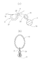
以下、本発明の実施の形態を図面に基づいて説明する。本実施形態は、図1に示すように、ルアー本体10の頭部Hの近傍の頭側腹部11に錘用フック2が設けられ、この錘用フック2には外付け錘3が装着できるように構成されている。また、ルアー本体10の尾部Tの近傍12における背部には、フック用リング13を介して釣り針4が吊設されている。なお、本実施形態において使用される釣り針4は、後述するように、二つの針先を有するいわゆるダブルフック型の釣り針である(図3参照)。これらの釣り針の基部41には環状の取付部42が設けられ、上記フック用リング13と環状取付部42の環状部分が直交方向に連結されるため、釣り針4の基部41は、自在な方向に向きを変更できるようになっている。また、ルアー本体10の頭部Hには、所定面積を有する板状部材(いわゆるリップ)5が突設され、さらに、このリップ5の根元付近には、釣り糸Lを連結するためのアイレット6が設けられている。
Hereinafter, embodiments of the present invention will be described with reference to the drawings. In the present embodiment, as shown in FIG. 1, a
ここで、外付け錘3の装着構造について詳述する。図1および図2(a)に示すように、錘用フック2は、弾性変形可能な(例えば金属製の)線状部材を湾曲して構成されており、その湾曲部分21は弧状に形成されている。また、錘用フック2の先端は、上記湾曲部分21の湾曲方向とは反対向きに折曲され、フック2の開口案内部22が形成されている。そして、この開口案内部22は、ルアー本体の表面から僅かな間隙Xを有するように構成されており、この間隙Xの幅寸法は外付け錘3に設けられる取付リング31の肉厚寸法よりも狭く構成されている。
Here, the mounting structure of the
他方、外付け錘3は、図2(a)において図示されているように、円環状の取付リング31が設けられるとともに、このリング31の先端に錘体32が装着されており、上記取付リング31に錘用フック2を挿通させることにより外付け錘3がルアー本体10に装着されるようになっている。従って、外付け錘3のリング31の貫通孔部分33に対して上記開口案内部22を先頭にして錘用フック2を挿通させるときには、当該リング31の一部をルアー本体10の表面と開口案内部22との隙間を通過させることによって、錘用フック2がリング31の内部に挿通されることとなり、その装着を完了させることができるものである。しかしながら、上述のとおり、ルアー本体10の表面と開口案内部22との間隙Xの幅寸法が上記リング31の肉厚寸法よりも狭くなっていることから、上記間隙Xにリング31の一部を通過させる場合には、当該間隙Xが一時的に広げる必要がある。そこで、当該錘用フック2を弾性変形可能な(例えば金属製の)材料で構成することにより、当該間隙Xをリング31が通過するときのみ、錘用フック2が弾性変形し、当該間隙Xの幅寸法を拡大させることができる。そして、通過後において再び錘用フック2が弾性変形の終了により復元することとなるため、間隙Xの幅寸法が再び縮小して、当該リング31が錘用フック2から容易に離脱できないようになっている。
On the other hand, as shown in FIG. 2A, the
また、図2(a)および(b)に示すように、上記錘用フック2を構成する線状部材は、その長手方向がルアー本体10の尾部Tから頭部Hに向かって延出し、その開口案内部22は、ルアー本体10の頭部Hに向かって開口するように、その方向が調整されているとともに、その設置範囲は、常にルアー本体10の左右方向の中央に沿った位置するように設けられている。そのため、錘用フック2に取り付けられた外付け錘3は、そのリング31が錘用フック2の湾曲部分21のいずれの部分に当接している場合においても、ルアー本体10の左右方向中央に対して重量を付与することとなる。また、外付け錘3を錘用フック2に装着し、または取り外す際には、いずれの場合も錘用フック2の全体に対し、ルアー本体10の頭部Hの側から操作することとなる。これは、外付け錘3が錘用フック2から容易に離脱しないための構成である。すなわち、キャスティング前におけるルアー1は、釣り糸Lによって吊り下げられる状態となるため、釣り糸Lが連結されるアイレット6を上にした状態となり、アイレット6はルアー本体10の頭部Hに設けられる(一般的なルアーは頭部付近に設けられる)ため、釣り糸Lによって吊り下げられたルアー本体10は、頭部Hを上に尾部を下にした状態となる。従って、上記のような吊下状態において外付け錘3が錘用フック2から離脱できないようになっているのである。また、キャスティング時においても、飛行するルアー本体10は、重量部分を前向き、釣り糸Lが連結する部分(頭部H)を後ろ向きとした姿勢をとるため、本実施形態においても外付け錘3が飛行を先導することとなるが、このとき、釣り糸Lは上記飛行によって引っ張られるようにして、キャスティングポイントまで釣り糸Lを延長させることができるのであることから、アイレット6は進行方向に対して後方に位置することとなるのである。従って、この場合においても、外付け錘3は錘用フック2の開口案内部22とは反対方向に慣性力を作用させることとなるから、これまた外付け錘3の離脱を防止している。
2A and 2B, the linear member constituting the
さらに、水中におけるルアー1は、リーリングによって、釣り糸Lがアイレット6を引っ張ることとなり、このとき、アイレット6を先頭にして釣り糸Lが引っ張る方向にルアー本体10が移動することとなるが、外付け錘3は、ルアー1の全体が移動するとき、錘用フック2を介して最後に引っ張られることとなるため、リーリング時おいても外付け錘3は尾部Tの方向に移動することとなるため、当該外付け錘3の離脱が防止されるのである。
Furthermore, the
このように、外付け錘3が離脱し難い状態でルアー本体10に装着されることにより、水中におけるルアー1の重量バランスを利用者が調整できることとなり、利用者の所望の姿勢を水中で実現させることが可能となる。なお、上記外付け錘3として使用する錘体32がタングステンを主とする材質とすることにより、小型でありながら大重量に構成することが可能となり、水中における浮力を考慮しても十分な重量を得ることができるとともに、小型であるため、水中を移動する際にも水の抵抗力の作用が小さくなり、ルアー本体10の外部に取り付けられていることによる影響を最小限なものとすることができる。さらに、根掛かり等により外付け錘3がルアー1から離脱し、または、釣り糸Lの切断等によりルアー1が釣り糸Lから離脱する場合であっても、鉛を使用していないことから鉛害を防止することができる。
Thus, by attaching the
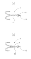
次に、釣り針4の一時的固定について詳述する。本実施形態で使用する釣り針は、上述のとおりダブルフックと呼ばれるものであり、図3(a)に示すように、2つの針先を有しつつ基部41は、2本の棒状部材が接近した構造となっている。このような基部の構造は、図示のように、2本の針先が鋭角方向に折曲する形態の場合も、180°の角度で反対向きに折曲する形態の場合も同様である。そこで、本実施形態では、図3(b)に示すように、薄肉の突片7をルアー本体10から突出するように設けておき(図1参照)、釣り針4の基部41を構成する2本の棒状部材で上記突片7を挟むように、すなわち、突片7が2本の棒状部材の間隙に挿入させるように、当該釣り針4の位置を調整することにより、当該釣り針4は、突片7によって一時的に固定されることとなるのである。
Next, the temporary fixing of the
そして、上記のような突片7は、適宜面積を有するものであるため、その表面がルアー本体10の進行方向に対して有角的であるときには、その進行方向またはルアー本体10の動きを左右させることとなって不都合である。すなわち、リップルアーにおけるリップの役割と同様の作用を与えることとなってしまうのである。そこで、本実施形態における突片7は、その表面を進行に対して平行に、つまり、ルアー本体10の前後方向に対して角度を有しない状態で設置されているのである。
Since the protruding
このように、突片7とダブルフック型の釣り針4とによって、当該釣り針4をルアー本体10に一時的に固定することにより、リーリング時におけるルアー1の移動の際には、釣り針4がルアー本体10の周辺をフラフラと揺動することを回避し、機敏なルアーアクションを実現し、釣りの対象魚による捕食があったときには、釣り針4は突片7から離脱可能となり、ルアー本体10から離れようと暴れて向きを変化させる魚の動きにあわせて釣り針4が自在に向きを変化させ得ることができる。また、釣り針4が一時的固定されている場合も固定されていない場合も、突片7の表面は進行方向に対して角度を有していないため、リーリング時におけるルアー1の進行に影響を与えることがない。
In this way, by temporarily fixing the
次に、本実施形態の他の使用態様について説明する。図4は、錘3をルアー1から取り外し、釣り針4をルアー本体10の腹部に吊説した状態を示している。このような使用形態は、錘3を外して軽量化することによって、海中又は湖中等の中層から浅層でルアー1を進行させる場合にとり得るものである。図示のとおり、ルアー本体10の腹部には、予めフック取付用突片8が装着されており、このフック取付用突片8の取付孔81にダブルフック型の釣り針4を構成する二つの針先のうち片方を挿入することにより、当該取付孔81に環状の取付部42を連結させることができるものである。上記フック取付用突片8は、適宜面積を有する板状に構成されているため、前述の突片7と同様に、その表面をルアー1の進行方向に対して平行となるように設けられている。従って、釣り針4が取り付けられていると否とにかかわらず、ルアー1の水中における進行に影響がないようになっている。また、フックの装着のためにリングを使用せず、このフック取付用突片8を使用することにより、釣り針4を装置しない状態(図1に示す状態)において、海底又は湖底等の付近をリーリングするとき、根掛かりの原因となる水草等に絡まることを防止できるのである。
Next, other usage modes of the present embodiment will be described. FIG. 4 shows a state in which the
このように、錘3の取り外しを可能にすることから、釣り針4をも取り外しができる構造とすることにより、ルアー1を所望の目的で使用することができるのである。
In this way, since the
本発明の実施形態は上記のとおりであるが、本発明の趣旨を逸脱しない範囲において種々の態様をとることができる。たとえば、上記実施形態および図面において一個の錘用フック2を設けた構成としているが、この錘用フック2を場所を異ならせて複数設ける形態とすることができる。この場合においても線状部材である錘用フック2は、ルアー本体10の前後方向中心線に沿った方向に延出させることが必要である。また、外付け錘3は、重量を変えた複数の種類を用意し、所望のアクションを実現させるために必要な重量を選択して使用できるようにすることが望ましい。
The embodiment of the present invention is as described above, but various modes can be taken without departing from the spirit of the present invention. For example, although a
1 ルアー
2 錘用フック
3 外付け錘
4 ダブルフック型の釣り針
5 リップ
6 アイレット
7 突片
8 フック取付用突片
10 ルアー本体
11 ルアー本体の頭部近傍
12 ルアー本体の後端付近
13 フック用リング
21 錘用フックの湾曲部分
22 案内開口部
31 錘用リング
32 錘体
33 貫通孔部分
41 釣り針基部
42 環状取付部
81 フック取付孔
H ルアー本体頭部
L 釣り糸
T ルアー本体尾部
X 間隙
1
Claims (4)
Priority Applications (1)
| Application Number | Priority Date | Filing Date | Title |
|---|---|---|---|
| JP2006248884A JP5111814B2 (en) | 2006-09-14 | 2006-09-14 | Lure |
Applications Claiming Priority (1)
| Application Number | Priority Date | Filing Date | Title |
|---|---|---|---|
| JP2006248884A JP5111814B2 (en) | 2006-09-14 | 2006-09-14 | Lure |
Publications (2)
| Publication Number | Publication Date |
|---|---|
| JP2008067639A JP2008067639A (en) | 2008-03-27 |
| JP5111814B2 true JP5111814B2 (en) | 2013-01-09 |
Family
ID=39289814
Family Applications (1)
| Application Number | Title | Priority Date | Filing Date |
|---|---|---|---|
| JP2006248884A Expired - Fee Related JP5111814B2 (en) | 2006-09-14 | 2006-09-14 | Lure |
Country Status (1)
| Country | Link |
|---|---|
| JP (1) | JP5111814B2 (en) |
Cited By (1)
| Publication number | Priority date | Publication date | Assignee | Title |
|---|---|---|---|---|
| JP5697285B1 (en) * | 2014-01-24 | 2015-04-08 | 充秀 西川 | Fishing hard lure |
Families Citing this family (5)
| Publication number | Priority date | Publication date | Assignee | Title |
|---|---|---|---|---|
| US7716871B1 (en) * | 2007-08-09 | 2010-05-18 | Joe Sayers | Fishing lure |
| JP2012024064A (en) * | 2010-07-22 | 2012-02-09 | Hikaru Kasuga | Upward fixed rear hook |
| US20160330945A1 (en) * | 2015-05-12 | 2016-11-17 | Clam Corporation | Lure weights and methods of using the same |
| US10842140B1 (en) * | 2016-10-25 | 2020-11-24 | Jesse Watson | Fishing lure system |
| JP7219938B1 (en) | 2021-08-24 | 2023-02-09 | 株式会社やまと社 | lure |
Family Cites Families (10)
| Publication number | Priority date | Publication date | Assignee | Title |
|---|---|---|---|---|
| JPS59122422U (en) * | 1983-02-07 | 1984-08-17 | 日商販株式会社 | Futsuku |
| JPH0320384Y2 (en) * | 1986-09-18 | 1991-05-01 | ||
| JPS6432066U (en) * | 1987-08-21 | 1989-02-28 | ||
| JPH0318760U (en) * | 1989-07-06 | 1991-02-25 | ||
| JPH11289921A (en) * | 1998-04-10 | 1999-10-26 | Risento:Kk | Fishing sinker and fishing lure |
| JP2000253788A (en) * | 1999-03-09 | 2000-09-19 | Shingo Mase | Assistant tool for casting |
| JP4636576B2 (en) * | 2000-11-30 | 2011-02-23 | グローブライド株式会社 | Pseudo fishing bait and weight used therefor |
| JP3844681B2 (en) * | 2001-11-27 | 2006-11-15 | 株式会社シマノ | Lure |
| JP2005065667A (en) * | 2003-08-21 | 2005-03-17 | Duel:Kk | Lure |
| JP4753350B2 (en) * | 2005-01-21 | 2011-08-24 | 株式会社イマカツ | Fish type lure |
-
2006
- 2006-09-14 JP JP2006248884A patent/JP5111814B2/en not_active Expired - Fee Related
Cited By (1)
| Publication number | Priority date | Publication date | Assignee | Title |
|---|---|---|---|---|
| JP5697285B1 (en) * | 2014-01-24 | 2015-04-08 | 充秀 西川 | Fishing hard lure |
Also Published As
| Publication number | Publication date |
|---|---|
| JP2008067639A (en) | 2008-03-27 |
Similar Documents
| Publication | Publication Date | Title |
|---|---|---|
| JP5111814B2 (en) | Lure | |
| AU2011231456B2 (en) | Fishing lure | |
| KR102620407B1 (en) | Fishing rig | |
| JP2018143224A (en) | Lure | |
| JP6534360B2 (en) | Fishing tackle | |
| CN109997812B (en) | Bait fixing piece | |
| KR20200109240A (en) | Pseudo bait and split ring for pseudo bait | |
| JP4820794B2 (en) | Fishing line lock | |
| JP3210806U (en) | Lure | |
| JP6656719B1 (en) | Simulated bait, mounting member and pseudo bait body | |
| JP5121078B2 (en) | Pseudo fishing bait and weight used therefor | |
| JP4828252B2 (en) | Jig head | |
| JP2019140995A (en) | Bait holder and holder unit | |
| JP3217356U (en) | Fishing gear | |
| JP2017158444A (en) | Dead bait for fishing and fishhook holder for the bait | |
| JP4907570B2 (en) | Lure | |
| JP2008113647A (en) | Lure | |
| DK1813149T3 (en) | Artificial fish bait of the metal head type | |
| JP6364344B2 (en) | Fishhook locking jig | |
| JP2020061951A (en) | Lure which can be subsided in creeping posture | |
| JP5981152B2 (en) | Ripple Are | |
| JP2005065667A (en) | Lure | |
| CN111713467A (en) | Bait for fishing | |
| JP3241271U (en) | lure | |
| JP5530666B2 (en) | Egi |
Legal Events
| Date | Code | Title | Description |
|---|---|---|---|
| A621 | Written request for application examination |
Free format text: JAPANESE INTERMEDIATE CODE: A621 Effective date: 20090910 |
|
| A977 | Report on retrieval |
Free format text: JAPANESE INTERMEDIATE CODE: A971007 Effective date: 20110905 |
|
| A131 | Notification of reasons for refusal |
Free format text: JAPANESE INTERMEDIATE CODE: A131 Effective date: 20111101 |
|
| A521 | Request for written amendment filed |
Free format text: JAPANESE INTERMEDIATE CODE: A523 Effective date: 20111215 |
|
| TRDD | Decision of grant or rejection written | ||
| A01 | Written decision to grant a patent or to grant a registration (utility model) |
Free format text: JAPANESE INTERMEDIATE CODE: A01 Effective date: 20120925 |
|
| A01 | Written decision to grant a patent or to grant a registration (utility model) |
Free format text: JAPANESE INTERMEDIATE CODE: A01 |
|
| A61 | First payment of annual fees (during grant procedure) |
Free format text: JAPANESE INTERMEDIATE CODE: A61 Effective date: 20121010 |
|
| FPAY | Renewal fee payment (event date is renewal date of database) |
Free format text: PAYMENT UNTIL: 20151019 Year of fee payment: 3 |
|
| R150 | Certificate of patent or registration of utility model |
Ref document number: 5111814 Country of ref document: JP Free format text: JAPANESE INTERMEDIATE CODE: R150 Free format text: JAPANESE INTERMEDIATE CODE: R150 |
|
| R250 | Receipt of annual fees |
Free format text: JAPANESE INTERMEDIATE CODE: R250 |
|
| R250 | Receipt of annual fees |
Free format text: JAPANESE INTERMEDIATE CODE: R250 |
|
| LAPS | Cancellation because of no payment of annual fees |