JP5111652B2 - Backlight device and control method of backlight device - Google Patents
Backlight device and control method of backlight device Download PDFInfo
- Publication number
- JP5111652B2 JP5111652B2 JP2011234584A JP2011234584A JP5111652B2 JP 5111652 B2 JP5111652 B2 JP 5111652B2 JP 2011234584 A JP2011234584 A JP 2011234584A JP 2011234584 A JP2011234584 A JP 2011234584A JP 5111652 B2 JP5111652 B2 JP 5111652B2
- Authority
- JP
- Japan
- Prior art keywords
- light
- backlight
- intensity
- display panel
- cell
- Prior art date
- Legal status (The legal status is an assumption and is not a legal conclusion. Google has not performed a legal analysis and makes no representation as to the accuracy of the status listed.)
- Active
Links
Images


Classifications
-
- Y—GENERAL TAGGING OF NEW TECHNOLOGICAL DEVELOPMENTS; GENERAL TAGGING OF CROSS-SECTIONAL TECHNOLOGIES SPANNING OVER SEVERAL SECTIONS OF THE IPC; TECHNICAL SUBJECTS COVERED BY FORMER USPC CROSS-REFERENCE ART COLLECTIONS [XRACs] AND DIGESTS
- Y02—TECHNOLOGIES OR APPLICATIONS FOR MITIGATION OR ADAPTATION AGAINST CLIMATE CHANGE
- Y02B—CLIMATE CHANGE MITIGATION TECHNOLOGIES RELATED TO BUILDINGS, e.g. HOUSING, HOUSE APPLIANCES OR RELATED END-USER APPLICATIONS
- Y02B20/00—Energy efficient lighting technologies, e.g. halogen lamps or gas discharge lamps
- Y02B20/40—Control techniques providing energy savings, e.g. smart controller or presence detection
Landscapes
- Liquid Crystal (AREA)
- Planar Illumination Modules (AREA)
- Circuit Arrangement For Electric Light Sources In General (AREA)
Description
本発明は、バックライトからの光を例えば液晶表示パネルにより変調することで画像の表示を行う画像表示装置及びこれに用いられるバックライト装置に関し、特に、画像表示領域を複数の領域に分割し、各領域のバックライトの明るさを制御するように構成された画像表示装置及びこれに用いられるバックライト装置に関する。 The present invention relates to an image display device that displays an image by modulating light from a backlight using, for example, a liquid crystal display panel, and a backlight device used therefor, in particular, an image display region is divided into a plurality of regions, The present invention relates to an image display device configured to control the brightness of a backlight in each region and a backlight device used therefor.
表示装置は、CRT(Cathode Ray Tube)などの自発光型の表示装置と、液晶ディスプレイ(液晶表示装置,液晶表示パネルとも呼ぶ)などの非発光型の表示装置に大別できる
。
Display devices can be broadly classified into self-luminous display devices such as CRT (Cathode Ray Tube) and non-luminous display devices such as liquid crystal displays (also referred to as liquid crystal display devices and liquid crystal display panels).
非発光型の表示装置としては、画像信号に応じて光の反射光量を調節する反射型の光変調素子を用いるものと、画像信号に応じて光の透過光量を調整する透過型の光変調素子を用いるものがある。特に、透過型の光変調素子として液晶表示パネルを用い、その裏面に照明装置(バックライトとも呼ぶ)を備える液晶表示装置は薄型,軽量であることから、コンピュータのモニターやテレビなどさまざまな表示装置に採用されている。 Non-light-emitting display devices that use a reflective light modulation element that adjusts the amount of reflected light according to an image signal and a transmissive light modulation element that adjusts the amount of light transmitted according to an image signal Some use In particular, a liquid crystal display device that uses a liquid crystal display panel as a transmissive light modulation element and has a lighting device (also called a backlight) on its back surface is thin and lightweight, so various display devices such as computer monitors and televisions Has been adopted.
ここで、液晶表示装置における、バックライト方式は、直下方式、エッジライト方式の2通りに大別される。直下方式は、液晶表示パネルの直下に光源となる蛍光管やLED(Light Emitting Diode)を配列する方式である。エッジライト方式は、アクリル板等で作成された板状の導光板の端部(エッジ部)に光源となる蛍光管やLEDを配置し、導光板内部での多重反射を利用して面光源とするようにしたものである。 Here, the backlight method in the liquid crystal display device is roughly classified into two types, a direct method and an edge light method. The direct method is a method in which fluorescent tubes and LEDs (Light Emitting Diodes) serving as light sources are arranged directly under a liquid crystal display panel. In the edge light system, a fluorescent tube or LED serving as a light source is arranged at an end (edge portion) of a plate-shaped light guide plate made of an acrylic plate or the like, and a surface light source is used by using multiple reflections inside the light guide plate. It is what you do.
ところで、CRTに代表される自発光型の表示装置では、画像を表示する際、画像信号に応じて特定の画素を必要な光量で選択的に発光させている。また、画質の面では、電子ビームの偏向中心との距離の関係から、画面中心からNTSCテレビ方式の標準観視画角である標準視野(水平:±15°、上:8°、下:12°)の輝度が、画面周辺部に対して相対的に高くなっている。人間は、標準視野内以外の輝度が、標準視野内の輝度と同等又はそれ以上である場合、視覚上の違和感を覚えることから、人間が有する視覚範囲有効視野の範囲において、人間の視覚に違和感のない画像表示を行うことが可能となっている。 By the way, in a self-luminous display device typified by a CRT, when an image is displayed, specific pixels are selectively made to emit light with a necessary light amount in accordance with an image signal. In terms of image quality, the standard field of view (horizontal: ± 15 °, upper: 8 °, lower: 12), which is the standard viewing angle of the NTSC television system from the center of the screen, due to the distance from the deflection center of the electron beam. The brightness of °) is relatively high with respect to the periphery of the screen. Humans feel uncomfortable when the brightness outside the standard field of view is equal to or higher than the brightness within the standard field of view. It is possible to perform image display without any problem.
これに対し、一般に液晶表示装置のような非発光型の表示装置では、画像信号に関わらずバックライトは常に一定の明るさで発光させている。したがって、バックライトの明るさは通常、画面の明るさ(輝度とも呼ぶ)が最大となるよう発光する。そのため、CRTに比べ、視覚上の仮想的な違和感から、画質面で物足りなさがあった。 On the other hand, in general, in a non-light-emitting display device such as a liquid crystal display device, the backlight always emits light with a constant brightness regardless of the image signal. Therefore, the backlight usually emits light so that the screen brightness (also referred to as luminance) is maximized. Therefore, compared with the CRT, the image quality is unsatisfactory due to a visually unnatural feeling.
上記課題に対し、従来からバックライトの明るさを制御することで人間が有する視覚範囲有効視野の範囲において、人間の視覚に違和感のない画像表示を行う液晶表示装置が提案されている。従来、この種の技術としては、たとえば、特許文献1に記載されたものが知られている。 In order to solve the above problems, a liquid crystal display device has been proposed that displays an image that does not give a sense of incongruity to human vision within the effective visual field range of human vision by controlling the brightness of the backlight. Conventionally, as this type of technology, for example, one described in Patent Document 1 is known.
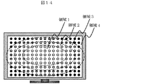
特許文献1には、光源にLEDを使用した直下方式のバックライトにおいて、例えば図14に示すように、バックライトを画面中央から略同心円状に複数の領域(領域1〜領域4)に分け、領域毎に光源の輝度を制御することで人間の視覚に違和感のない画像表示を行いつつ、消費電力を低減することが開示されている。 In Patent Document 1, in a direct backlight using an LED as a light source, for example, as shown in FIG. 14, the backlight is divided into a plurality of regions (regions 1 to 4) in a substantially concentric manner from the center of the screen. It is disclosed that power consumption is reduced while displaying an image that does not give a sense of incongruity to human vision by controlling the luminance of a light source for each region.
しかしながら、上記特許文献1に記載の従来の液晶表示装置では、次のような問題点があった。 However, the conventional liquid crystal display device described in Patent Document 1 has the following problems.
一つ目は、バックライト構造の違いによる輝度分布の違いが考慮されていない点である
。直下方式では、ひとつの光源からの光の入射方向が液晶表示パネルに対して略垂直となり、液晶表示パネルに入射する光の拡がり方は、一様に均一な輝度分布を得ることが可能である。一方、エッジライト方式においては、導光板の多重反射を利用した面光源であるため、光の入射方向による光の拡がり方の違いがあり、一様に均一な輝度分布を得ることが難しい。
The first is that the difference in luminance distribution due to the difference in backlight structure is not taken into consideration. In the direct type, the incident direction of light from one light source is substantially perpendicular to the liquid crystal display panel, and it is possible to obtain a uniform and uniform luminance distribution as to how the light incident on the liquid crystal display panel spreads. . On the other hand, since the edge light system is a surface light source using multiple reflection of the light guide plate, there is a difference in how light spreads depending on the incident direction of light, and it is difficult to obtain a uniform and uniform luminance distribution.
二つ目は、分割された領域毎の発光輝度を略同心円状に制御するため、画像信号および/もしくはユーザが選択する映像モードに応じて動的に制御するシステムに適用した場合
、映像によっては臨場感が損なわれてしまう点である。例えば、全体的に暗い映像の画面端部に明るい物体が存在する場合、人間の注視点は明るい物体に向かうが、バックライトを画面中央から略同心円状に光源の輝度を制御することで、明るい物体の輝度が下がり、映像が与えるインパクトが減少してしまう。
Second, in order to control the light emission luminance of each divided area in a substantially concentric manner, when applied to a system that dynamically controls according to an image signal and / or a video mode selected by the user, depending on the video, It is the point that the sense of reality is lost. For example, when a bright object is present at the edge of a screen that is totally dark, the human gaze point is directed toward the bright object, but the backlight is brightened by controlling the brightness of the light source in a substantially concentric manner from the center of the screen. The brightness of the object is lowered and the impact of the image is reduced.
本発明は、上記課題に鑑みなされたもので、エッジライト方式を用いたバックライト装置及びこれを用いた画像表示装置において、消費電力を低減しつつも高品位な画像を表示することが可能な技術を提供するものである。 The present invention has been made in view of the above problems, and in a backlight device using an edge light system and an image display device using the same, it is possible to display a high-quality image while reducing power consumption. Provide technology.
前記目的は、その一例として特許請求の範囲に記載の構成により達成できる。 The object can be achieved by the configuration described in the claims as an example.
この発明の構成によれば、エッジライト方式を用いたバックライトにおいて、画面周辺部の輝度を中央部に比べて相対的に下げるシェーディング処理によって消費電力を低減しつつも、高品位な画像を表示することが可能となる。 According to the configuration of the present invention, in a backlight using an edge light method, a high-quality image is displayed while reducing power consumption by shading processing that lowers the luminance of the peripheral portion of the screen relative to the central portion. It becomes possible to do.
以下、本発明の実施形態について、図面を用いて詳細に説明する。 Hereinafter, embodiments of the present invention will be described in detail with reference to the drawings.
図1(a)は、本発明の第1の実施例に係る液晶表示装置における、エッジライト FIG. 1A shows an edge light in a liquid crystal display device according to a first embodiment of the present invention.
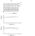
方式のバックライト装置概略図を示している。このバックライト装置は、複数のバックライトセル(101)をマトリクス状に複数配列して液晶表示パネル(図示せず)の表示領域(100)全体を照明するように構成されている。この表示領域(100)は、バックライト装置の照射面(つまりバックライトセル(101)の面積の総和)の大きさとほぼ等しいものとする。 1 shows a schematic diagram of a backlight device of the type. This backlight device is configured to illuminate the entire display area (100) of a liquid crystal display panel (not shown) by arranging a plurality of backlight cells (101) in a matrix. This display area (100) is assumed to be approximately equal to the size of the irradiation surface of the backlight device (that is, the total area of the backlight cells (101)).
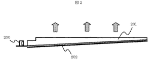
各バックライトセル(101)の一構成例を図2に示す。各バックライトセル(101
)は、それぞれ、LED光源(200)と導光板(201)及び反射板(202)を備えている。導光板(201)は、図1(a)に示されるように、上から(バックライト装置からの光の照射方向の対向する側から)見たときに矩形状を為しており、また、そのバックライト装置照射面の縦方向断面は、図2に示されるように、光が入射される端部からそれに対抗する先端部にかけて徐々に厚さが薄くなる楔状を為している。これによって、光入射端部から先端部にかけて出射光の輝度分布が均一になるようにされる。
One structural example of each backlight cell (101) is shown in FIG. Each backlight cell (101
) Each include an LED light source (200), a light guide plate (201), and a reflection plate (202). As shown in FIG. 1 (a), the light guide plate (201) has a rectangular shape when viewed from above (from the side opposite to the light irradiation direction from the backlight device). As shown in FIG. 2, the longitudinal cross section of the backlight device irradiation surface has a wedge shape in which the thickness gradually decreases from the end where the light is incident to the front end facing the light. Thereby, the luminance distribution of the emitted light is made uniform from the light incident end portion to the tip end portion.
図2において、LED光源(200)は導光板(201)の上端部側に配置されており
、上側から下側に向けて、光を導光板(201)出射する。LED光源(200)からの厚さが厚いほうの端部(エッジ部分)に入射され、導光板(201)内で多重反射させ、その上面から液晶表示パネル方向(図中矢印方向)へ光を出射する。また導光板(201
)の下面から導光板(201)外に透過した光は、導光板(201)の下面の下部に配置された反射板(202)により反射されて再び導光板(201)に戻り、導光板(201
)の上面から出射される。これにより、LED等の点光源を面光源に変換している。尚、本実施例では、LED光源(200)として、電極面と平行な方向に光を出射するサイドビュー型のLEDを用いているが、電極面と直交する方向に光を出射するトップビュー型のLEDを用いてもよい。
In FIG. 2, the LED light source (200) is disposed on the upper end side of the light guide plate (201), and emits light from the upper side to the lower side. The light from the LED light source (200) is incident on the thicker end portion (edge portion), subjected to multiple reflection in the light guide plate (201), and light is emitted from the upper surface toward the liquid crystal display panel (arrow direction in the figure). Exit. The light guide plate (201
The light transmitted from the lower surface of the light guide plate (201) to the outside of the light guide plate (201) is reflected by the reflection plate (202) disposed at the lower portion of the lower surface of the light guide plate (201) and returns to the light guide plate (201). 201
). Thereby, a point light source such as an LED is converted into a surface light source. In this embodiment, as the LED light source (200), a side view type LED that emits light in a direction parallel to the electrode surface is used, but a top view type that emits light in a direction orthogonal to the electrode surface. LED may be used.
図3は、各バックライトセル(101)からの光の強度を独立に制御可能とした液晶表示装置の模式図である。本実施例では、液晶表示装置は、バックライトセル(101)を
、画面水平方向(x軸)に6個、垂直方向(y軸)に5個配列してバックライト装置の照射面を30領域に分割している。また、LED光源(200)は、画面上部から下部に向かって光を出射するものとする。各バックライトセル(101)にはLED光源(200
)が2つずつ設けられており、この2個のLED光源(200)を一組とし、この一組のLED光源(200)を制御単位として各バックライトセル(101)から出射される光の強度が制御される。各バックライトセル(101)のLED光源(200)の個数は2個に尾限定されるものではなく、例えば1個でも3個でもよい。各バックライトセル(101)、すなわちバックライト装置照射面の領域の位置は、図3中のx軸及びy軸方向に
羅列した英数字(1〜6及びA〜E)で特定するものとする。
FIG. 3 is a schematic diagram of a liquid crystal display device in which the intensity of light from each backlight cell (101) can be controlled independently. In this embodiment, the liquid crystal display device has six backlight cells (101) arranged in the horizontal direction (x-axis) and five in the vertical direction (y-axis), and the irradiation surface of the backlight device has 30 regions. It is divided into. The LED light source (200) emits light from the upper part of the screen toward the lower part. Each backlight cell (101) has an LED light source (200).
) Are provided in pairs, and the two LED light sources (200) are set as a set, and the light emitted from each backlight cell (101) is controlled by using the set of LED light sources (200) as a control unit. The intensity is controlled. The number of LED light sources (200) in each backlight cell (101) is not limited to two, and may be one or three, for example. The position of each backlight cell (101), that is, the region of the backlight device irradiation surface, is specified by alphanumeric characters (1 to 6 and A to E) listed in the x-axis and y-axis directions in FIG. .
ここで、各バックライトセル(101)から出射される光の強度は、そのバックライトセル(101)に対応する表示領域の部分における映像信号の最大輝度により制御される
。例えば、領域C3に対応する表示領域の部分における映像信号の最大輝度が127の場合、当該表示装置で表現可能な最大の輝度を255とすると、当該領域の最大輝度は表現可能な最大輝度の1/2なので、領域C3の光強度はLED光源(200)の最大出力の約1/2とされる。また、例えば領域A1に対応する表示領域の部分における映像信号が0場合は、領域A1の光強度は例えば0とされる。これにより、映像信号に応じて、バックライト装置からの光強度を領域毎に(バックライトセル(101)単位で)、局所的に
制御することができる。
Here, the intensity of the light emitted from each backlight cell (101) is controlled by the maximum luminance of the video signal in the portion of the display area corresponding to the backlight cell (101). For example, when the maximum luminance of the video signal in the portion of the display area corresponding to the area C3 is 127 and the maximum luminance that can be expressed by the display device is 255, the maximum luminance of the area is 1 of the maximum luminance that can be expressed. Therefore, the light intensity in the region C3 is about ½ of the maximum output of the LED light source (200). For example, when the video signal in the display area corresponding to the area A1 is 0, the light intensity of the area A1 is 0, for example. Thereby, according to a video signal, the light intensity from a backlight apparatus can be locally controlled for every area | region (backlight cell (101) unit).
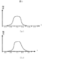
図4は、図3中の領域C3のバックライトセル(101)が発光した際のx軸方向(a
)及びy軸方向(b)輝度分布を示している。ここでは、領域C3に隣接する領域は消灯しているものとする。図に示す通り、領域C3の発光は隣接領域(C2、D4等)にも影響を与える。すなわち、ある領域の光はそれに隣接する領域に拡がる(漏れ込む)ようになっている。また、この光の拡がりは、図3に示されるようにx軸方向、y軸方向で異なっている。これは、エッジライト方式では、LED光源(200)からの光が液晶表示パネルに対して略平行に導光板(201)のエッジ部に入射し、導光板(201)内での多重反射を利用してその上面から出射するためである。上述のように導光板(201)は、入射端部から先端部にかけて出射光の輝度分布が均一になるように光入射端部から先端部にかけて漸次厚みが薄くなる楔形形状を為しているが、かかる形状であっても、光入射端部よりも先端部近傍のほうがLED光源(200)の光出射方向の先に位置するため光出射量が多くなる。例えば、図4(b)に示されるように、領域C3の輝度分布は、のLED光源(200)が配置される側(領域B3に近接する側)の方が、LED光源(200
)が配置されていない側(領域D3に近接する側)よりも、相対的に輝度が下がるといった、不均一な輝度分布を示す。一方、導光板形状はy軸を基準に対称性を持っているため
、図4(a)に示されるように、x軸方向の光の分布形状も略対称性を持っている。
4 shows the x-axis direction (a) when the backlight cell (101) in the region C3 in FIG.
) And y-axis direction (b) shows the luminance distribution. Here, it is assumed that the area adjacent to the area C3 is turned off. As shown in the figure, the light emission in the region C3 also affects adjacent regions (C2, D4, etc.). That is, light in a certain area spreads (leaks) into an adjacent area. Further, the spread of the light is different in the x-axis direction and the y-axis direction as shown in FIG. In the edge light system, light from the LED light source (200) is incident on the edge portion of the light guide plate (201) substantially parallel to the liquid crystal display panel, and multiple reflection in the light guide plate (201) is used. This is because the light is emitted from the upper surface. As described above, the light guide plate (201) has a wedge shape in which the thickness gradually decreases from the light incident end to the tip so that the luminance distribution of the emitted light is uniform from the incident end to the tip. Even in such a shape, the amount of light emission increases because the vicinity of the tip portion is positioned ahead of the light emission direction of the LED light source (200) rather than the light incident end portion. For example, as shown in FIG. 4B, the luminance distribution in the region C3 is such that the LED light source (200) is closer to the side where the LED light source (200) is disposed (the side closer to the region B3).
) Indicates a non-uniform luminance distribution in which the luminance is relatively lower than the side where the) is not disposed (the side closer to the region D3). On the other hand, since the light guide plate shape has symmetry with respect to the y-axis, as shown in FIG. 4A, the light distribution shape in the x-axis direction also has substantially symmetry.
かかる輝度特性を有するバックライトセル(101)を、同一輝度で点灯させた際の、画面中央部におけるy軸方向の輝度分布を図1(b)に示す。図4(b)のように、各バックライトセル(101)のy軸方向における輝度分布は、LED光源(200)側の方がLED光源(201)が配置されていない側よりも相対的に輝度が低いこと、及び、あるバックライトセル(例えばE行)はその上に隣接するバックライトセル(例えばD行)からの光の一部が入り込むために、画面上端部の輝度が画面下端部の輝度に比べ相対的に下がり、一画面において画面下端部が最大輝度(L1)となる現象が生じる。 FIG. 1B shows the luminance distribution in the y-axis direction at the center of the screen when the backlight cell (101) having such luminance characteristics is lit at the same luminance. As shown in FIG. 4B, the luminance distribution in the y-axis direction of each backlight cell (101) is relatively greater on the LED light source (200) side than on the side where the LED light source (201) is not disposed. Since the luminance is low, and a certain backlight cell (for example, E row) receives a part of light from the adjacent backlight cell (for example, D row), the luminance at the upper end of the screen is the lower end of the screen. A phenomenon occurs in which the lower end of the screen reaches the maximum brightness (L1).
そこで、本実施例では、画面中央部の輝度が、画面周辺部に対して相対的に高くなる輝度分布を得る為に、エッジライト方式におけるバックライトセル(101)の輝度分布形状を考慮して各バックライトセル(101)の出射光の強度を制御している。 Therefore, in this embodiment, in order to obtain a luminance distribution in which the luminance at the center of the screen is relatively higher than the peripheral portion of the screen, the luminance distribution shape of the backlight cell (101) in the edge light method is taken into consideration. The intensity of the emitted light of each backlight cell (101) is controlled.
図1(a)は、バックライト装置の照射面全体において、例えば全白表示時に最大輝度の光を出射する場合における本実施例に係る各バックライトセル(101)の制御の一例を示している。図1(a)において、各バックライトセル(101)の数字は、当該バックライトセル(101)に供給される、バックライトセル(101)の明るさを制御するための制御信号のレベルを示している。 FIG. 1A shows an example of the control of each backlight cell (101) according to the present embodiment in the case where light having the maximum luminance is emitted, for example, when displaying all white on the entire irradiation surface of the backlight device. . In FIG. 1A, the number of each backlight cell (101) indicates the level of a control signal for controlling the brightness of the backlight cell (101) supplied to the backlight cell (101). ing.
図1に示されるように、本実施例では、画面上部のバックライトセル(101)、図3
では領域A1〜A6に対応するバックライトセル(101)への制御信号を、最大輝度となる制御信号(例えば8bitで255)とし、一方、相対的に輝度がくなる画面下部のバックライトセルに対しては、例えば段階的に、上記画面上部のバックライトセル(101)への制御信号よりも制御信号を下げている。例えば、2列目及び3列目のバックライトセル(101)においては、A〜C行目(すなわち領域A2〜3A2、B2〜B3、C2〜C3)のバックライトセル(101)よりもD行目のバックライトセル(101)への制御信号が低く、更にE行目の画面最下部の領域(D2〜D3)は、D行目よりも更に低くなっている。また、x軸方向については、x軸中央から左右端部に向かうにつれて段階的に制御信号を下げており、画面左右端の領域(1列目及び6列目の領域)で最も制御信号が低くされている。すなわち、本実施例においては、バックライトセル(101)x軸方向及びy軸方向の位置により制御信号の値を変えており、相対的に輝度が高く、かつ画面中央部よりも輝度を下げたい左右下端部の領域E1及びE6の制御信号が、全バックライトセル(101)の中で最も低くされている。左右上端部の領域A1及びA6は相対的に輝度が低いため、左右下端部の領域E1及びE6よりも制御信号のレベルは低くされている。
As shown in FIG. 1, in this embodiment, the backlight cell (101) at the top of the screen, FIG.
Then, the control signal to the backlight cells (101) corresponding to the areas A1 to A6 is set to a control signal (for example, 255 in 8 bits) that has the maximum luminance, while the backlight cells at the lower portion of the screen where the luminance is relatively low. For example, the control signal is lowered stepwise from the control signal to the backlight cell (101) at the top of the screen. For example, in the backlight cells (101) in the second column and the third column, D rows than the backlight cells (101) in the A to C rows (that is, the regions A2 to 3A2, B2 to B3, and C2 to C3). The control signal to the backlight cell (101) of the eye is low, and the area at the bottom of the screen on the E line (D2 to D3) is lower than that of the D line. In the x-axis direction, the control signal is lowered step by step from the center of the x-axis toward the left and right edges, and the control signal is the lowest in the left and right edges of the screen (the first and sixth columns). Has been. That is, in this embodiment, the value of the control signal is changed depending on the position of the backlight cell (101) in the x-axis direction and the y-axis direction, and the luminance is relatively high and it is desired to lower the luminance than the center of the screen. The control signals in the left and right lower end regions E1 and E6 are the lowest among all the backlight cells (101). Since the areas A1 and A6 at the left and right upper ends are relatively low in luminance, the level of the control signal is set lower than the areas E1 and E6 at the left and right lower ends.
このように、本実施例では、エッジライト方式を用いたバックライトセルの輝度分布を補正するように各バックライトセルの発光輝度を制御することで、例えば図1(c)に示されるように、画面周辺部の輝度を画面中央部に比べ相対的に低い輝度分布を得ることが可能となり、上記輝度分布による輝度むらを低減しながら消費電力を低減することができる。以降、上述のように、バックライトセルの発光輝度を制御する信号のことを「シェーディング信号」、この処理、すなわち画面周辺部の輝度を画面中央部よりも相対的に低く
するための処理を「シェーディング処理」と呼ぶこととする。
As described above, in this embodiment, by controlling the light emission luminance of each backlight cell so as to correct the luminance distribution of the backlight cell using the edge light method, for example, as shown in FIG. Thus, it is possible to obtain a luminance distribution having a relatively low luminance at the periphery of the screen as compared to the central portion of the screen, and it is possible to reduce power consumption while reducing luminance unevenness due to the luminance distribution. Hereinafter, as described above, a signal for controlling the light emission luminance of the backlight cell is referred to as “shading signal”, and this processing, that is, processing for lowering the luminance at the peripheral portion of the screen relative to the central portion of the screen is described as “ This is called “shading process”.
上記シェーディング処理を含めたバックライト装置の光強度の制御を行うための回路構成の一例について、図5を参照しながら以下に説明する。図5は、本実施例に係る液晶表示装置に用いられるシェーディング処理を実行するための回路ブロックの一例を示している。 An example of a circuit configuration for controlling the light intensity of the backlight device including the shading process will be described below with reference to FIG. FIG. 5 shows an example of a circuit block for executing the shading process used in the liquid crystal display device according to the present embodiment.
本実施例の液晶表示装置は、同図に示すように、画面周辺部の輝度を画面中央部に比べ相対的に低い輝度分布を得る為のシェーディング信号生成部(500)と、画像フレーム受信部(501)と、画像処理部(502)と、バックライト制御部(503)と、画像信号補正部(504)と、バックライト駆動部(505)と、液晶制御部(506)と、H−ドライバ(507)と、V−ドライバ(508)と、液晶表示パネル(509)と、バックライト部(510)とを有している。 As shown in the figure, the liquid crystal display device according to the present embodiment includes a shading signal generation unit (500) for obtaining a luminance distribution that is relatively lower in luminance at the periphery of the screen than at the center of the screen, and an image frame reception unit. (501), an image processing unit (502), a backlight control unit (503), an image signal correction unit (504), a backlight driving unit (505), a liquid crystal control unit (506), and H- A driver (507), a V-driver (508), a liquid crystal display panel (509), and a backlight unit (510) are provided.
画像フレーム(501)受信部が受信した画像フレームは、画像信号処理部(502)へ送出される。該画像信号処理部(502)に入力された画像フレームは、各バックライトセル(101)の画像の特徴量、例えば最大輝度を検出し、この特徴量に応じて各バックライトセルの発光量を決定し、バックライト制御部(503)に制御信号を送出する。各バックライトセルの発光量は、例えば上述したようにバックライトセルに対応する表示領域の部分における映像信号の最大輝度とほぼ比例させるように決定してもよい。また、各バックライトセルの発光量を、減光率αを乗算することにより決定するようにしてもよい。この減光率αは、例えば、各領域の最大輝度が表現可能な最大輝度と等しい場合はα=1、表現可能な最大輝度の半分の場合は1/2、表現可能な最大輝度の10%の場合は1/10というように決められる。また、各領域の最大輝度は、当該領域の映像信号の輝度信号から検出してもよく、またRGB信号の各原色信号から検出してもよい。また、上記画像の特徴量は、例えば、各バックライトセル(101)に対応する画像の輝度ヒストグラムを個別に算出して検出することができる。画像の特徴量として、最大輝度以外に平均輝度(APL)や、あるバックライトセルの前画像フレームと現画像フレームとの輝度差分の情報等を用いてもよい。 The image frame received by the image frame (501) receiving unit is sent to the image signal processing unit (502). The image frame input to the image signal processing unit (502) detects the feature amount of the image of each backlight cell (101), for example, the maximum luminance, and the light emission amount of each backlight cell is determined according to this feature amount. The control signal is sent to the backlight control unit (503). For example, as described above, the light emission amount of each backlight cell may be determined so as to be approximately proportional to the maximum luminance of the video signal in the display area corresponding to the backlight cell. Alternatively, the amount of light emitted from each backlight cell may be determined by multiplying by the light reduction rate α. The light reduction rate α is, for example, α = 1 when the maximum luminance of each region is equal to the maximum luminance that can be expressed, 1/2 when the maximum luminance that can be expressed is 10%, and 10% of the maximum luminance that can be expressed. In this case, it is determined as 1/10. Further, the maximum luminance of each area may be detected from the luminance signal of the video signal in the area, or may be detected from each primary color signal of the RGB signal. Further, the feature amount of the image can be detected by, for example, individually calculating the luminance histogram of the image corresponding to each backlight cell (101). As the image feature amount, in addition to the maximum luminance, average luminance (APL), information on luminance difference between the previous image frame and the current image frame of a certain backlight cell, or the like may be used.
一方、シェーディング信号生成部(500)は、例えば図1(a)に示されるような制御信号を出力する。この制御信号の値は、例えば図1(b)に示されたバックライト装置の照射面における輝度分布等を考慮して予め設定される。 On the other hand, the shading signal generator (500) outputs a control signal as shown in FIG. The value of this control signal is set in advance in consideration of, for example, the luminance distribution on the irradiation surface of the backlight device shown in FIG.
画像信号処理部(502)で決定したバックライトセル(101)の発光量は、バックライト制御部(503)において、シェーディング信号生成部(500)によって生成した制御信号の重み付けをした後、バックライト駆動部(505)へ駆動信号として送出する。バックライト駆動部(505)は、バックライト駆動部(505)からの駆動信号に基づき各バックライトセル(101)のLED光源(201)を点灯制御する。 The light emission amount of the backlight cell (101) determined by the image signal processing unit (502) is weighted by the control signal generated by the shading signal generation unit (500) in the backlight control unit (503), and then the backlight. A drive signal is sent to the drive unit (505). The backlight drive unit (505) controls lighting of the LED light sources (201) of the respective backlight cells (101) based on the drive signal from the backlight drive unit (505).
シェーディング信号生成部(500)における制御信号を生成するための構成は、バックライトセル(101)は、ソフトウェアで実現してもよく、また図5の回路が1チップのICで構成される場合は、このICとは別に用意された、画像表示装置全体を制御するためのメインマイコンに上記ソフトウェアを組み込んでもよい。また、各バックライトセル(101)の制御信号を生成するためのデータ予め計算してROM等に代表されるメモリに記憶させておき、これをLUT(Look Up Table)として参照しながら制御信号を生
成してもよい。
The configuration for generating the control signal in the shading signal generation unit (500) may be realized by software for the backlight cell (101), and when the circuit of FIG. 5 is configured by a one-chip IC. The software may be incorporated in a main microcomputer that is prepared separately from the IC and controls the entire image display apparatus. Further, data for generating a control signal for each backlight cell (101) is calculated in advance and stored in a memory such as a ROM, and the control signal is referred to as a LUT (Look Up Table). It may be generated.
バックライト駆動部(505)において、バックライトを駆動する信号は、PWM(Pulse Width Modulation)もしくは振幅変調である。PWMの場合、PWM周波数は一定とし、発光強度に応じてON期間とOFF期間の比(デューティ比)を変化させて、LED光源(200)PWM制御する。また、PWM周波数は、液晶表示装置のフレーム周波数より高いもくしは同等程度であることが望ましい。 In the backlight drive unit (505), the signal for driving the backlight is PWM (Pulse Width Modulation) or amplitude modulation. In the case of PWM, the PWM frequency is constant, and the LED light source (200) PWM control is performed by changing the ratio (duty ratio) between the ON period and the OFF period according to the light emission intensity. Further, it is desirable that the PWM frequency is equal to or higher than the frame frequency of the liquid crystal display device.
また、画像信号処理部(502)で決定した各バックライトセル(101)の発光量に基づき画像信号補正部(504)は、画像信号を補正する。この補正は、例えば上記減光率αの逆数を増幅度として映像信号を増幅する処理である。例えば減光率αが1/2のときは、2倍の増幅度で映像信号を増幅する。このように画像信号補正部(504)で補正された映像信号は、水平及び垂直同期信号とともに液晶制御部(506)へ送出すれる。 The image signal correction unit (504) corrects the image signal based on the light emission amount of each backlight cell (101) determined by the image signal processing unit (502). This correction is, for example, a process of amplifying the video signal using the reciprocal of the light attenuation rate α as an amplification factor. For example, when the light attenuation rate α is ½, the video signal is amplified with a double amplification factor. The video signal corrected by the image signal correction unit (504) in this way is sent to the liquid crystal control unit (506) together with the horizontal and vertical synchronization signals.
液晶制御部(506)では、入力された映像信号と水平及び垂直同期信号に基づいて表示制御信号が生成され、H−ドライバ及びV−ドライバに送出される。H−ドライバでは
、液晶制御部(506)からの表示制御信号に基づいて表示信号が生成され、液晶表示パネル(209)へ送出される。V−ドライバでは水平及び垂直同期信号に同期した走査信号が生成され液晶表示パネル(509)へ印加される。液晶表示パネル(509)では、H−ドライバ及びV−ドライバからの信号により各走査電極と各データ電極とが駆動されることで、対応する画素領域に表示信号に対応した階調電圧が印加され、当該画素領域における液晶の応答が制御される。
In the liquid crystal control unit (506), a display control signal is generated based on the input video signal and the horizontal and vertical synchronization signals, and sent to the H-driver and V-driver. The H-driver generates a display signal based on the display control signal from the liquid crystal control unit (506) and sends it to the liquid crystal display panel (209). In the V-driver, a scanning signal synchronized with the horizontal and vertical synchronizing signals is generated and applied to the liquid crystal display panel (509). In the liquid crystal display panel (509), each scanning electrode and each data electrode are driven by signals from the H-driver and V-driver, so that a gradation voltage corresponding to the display signal is applied to the corresponding pixel region. The response of the liquid crystal in the pixel area is controlled.
このように本実施例では、エッジ方式のバックライト装置において、LED光源からの光の進行方向を考慮してバックライトセルの光強度を制御している。すなわち複数のバックライトセルのうち、光の進行方向の上流側端部に位置するバックライトセルの光強度を
、光の進行方向の下流側端部に位置するバックライトセルの光強度よりも相対的に高くしている。換言すれば、バックライト装置の照射面の第1端部(本実施例では上側の端部)に隣接するLED光源を持つバックライトセルの光強度をこの第1端部と対向する第2端部(本実施例では下側の端部)に隣接するバックライトセルの制御信号の値を大きくしている。これにより、エッジライト方式が有する輝度分布を考慮した制御信号によりシェーディング処理を行われ、輝度分布を補正しつつ画面周辺部の輝度を画面中央部に比べ相対的に低い輝度分布を得ることででき、良好な画質を得ながらも消費電力を低減することができる。
Thus, in this embodiment, in the edge type backlight device, the light intensity of the backlight cell is controlled in consideration of the traveling direction of the light from the LED light source. That is, among the plurality of backlight cells, the light intensity of the backlight cell located at the upstream end portion in the light traveling direction is relative to the light intensity of the backlight cell located at the downstream end portion in the light traveling direction. It is high. In other words, the light intensity of the backlight cell having the LED light source adjacent to the first end portion (the upper end portion in the present embodiment) of the irradiation surface of the backlight device is the second end facing the first end portion. The value of the control signal of the backlight cell adjacent to the portion (the lower end in this embodiment) is increased. As a result, shading processing is performed with a control signal that takes into account the luminance distribution of the edge light method, and the luminance distribution can be corrected to obtain a luminance distribution that is relatively low compared to the central portion of the screen while correcting the luminance distribution. In addition, power consumption can be reduced while obtaining good image quality.
尚、上記実施例では、バックライトの照射面を30領域に分割したが、これに限られるものではなく、これよりも少ない或いは多い領域に分割してもとい。また、各バックライトセルの光強度を映像信号の最大輝度で制御した例を示したが、これに限られること無く
、平均輝度レベル(APL)を用いて同様な制御を行ってもよい。さらにまた、各バックライトセルの導光板は、図2に示される形状以外のものも用いることができる。
In the above-described embodiment, the irradiation surface of the backlight is divided into 30 areas. However, the present invention is not limited to this, and it may be divided into smaller or more areas. Moreover, although the example which controlled the light intensity of each backlight cell by the maximum brightness | luminance of the video signal was shown, you may perform the same control using not only this but an average brightness level (APL). Furthermore, the light guide plate of each backlight cell may have a shape other than that shown in FIG.
次に図6及び図7を参照しつつ、本発明の第2実施例を説明する。この第2実施例は、バックライトセル(101)におけるLED光源(200)の実装位置及び光出射方向が実施例1と異なり、図6に示されるように、LED光源(200)が導光板の左端部側に設けられ、導光板に対してx軸方向と平行に光を入射する(本例では左から右へ光が入射する)構成としている。 Next, a second embodiment of the present invention will be described with reference to FIGS. The second embodiment differs from the first embodiment in the mounting position and the light emission direction of the LED light source (200) in the backlight cell (101), and as shown in FIG. 6, the LED light source (200) is a light guide plate. It is provided on the left end side, and has a configuration in which light is incident on the light guide plate in parallel with the x-axis direction (in this example, light is incident from left to right).
このようバックライトセル(101)の構造であっても、実施例1と同様に、上述した理由で各バックライトセル(101)のLED光源側が、LED光源が配置されていない側よりも、相対的に輝度が下がるといった不均一な輝度分布を示す。かかる場合において
、本実施例は、例えば図7に示されるように、領域L1〜L5にそれぞれ対応する前記シェーディング信号を下記の関係を満たすような値に設定し、図5に示されたシェーディング信号生成部(500)において生成するように構成している。
Even in such a structure of the backlight cell (101), as in the first embodiment, the LED light source side of each backlight cell (101) is more relative to the side where the LED light source is not disposed for the reasons described above. This shows a non-uniform luminance distribution in which the luminance decreases. In this case, in this embodiment, as shown in FIG. 7, for example, the shading signals respectively corresponding to the regions L1 to L5 are set to values satisfying the following relationship, and the shading signal shown in FIG. It produces | generates in a production | generation part (500).
L1>L2>L3>L4>L5
このように、エッジライト方式における光の入射方向に応じてシェーディング信号を変更することで、実施例1と同様な効果を得ることができる。このように本実施例では、エッジ方式のバックライト装置において、LED光源からの光の進行方向を考慮してバックライトセルの光強度を制御している。すなわち複数のバックライトセルのうち、光の進行方向の上流側端部に位置するバックライトセルの光強度を、光の進行方向の下流側端部に位置するバックライトセルの光強度よりも相対的に高くしている。換言すれば、バックライト装置の照射面の第1端部(本実施例では左側の端部)に隣接するLED光源を持つバックライトセルの光強度をこの第1端部と対向する第2端部(本実施例では右側の端部)に隣接するバックライトセルの制御信号の値を大きくしている。これにより、輝度分布を補正しつつ画面周辺部の輝度を画面中央部に比べ相対的に低い輝度分布を得ることででき
、良好な画質を得ながらも消費電力を低減することができる。
L1>L2>L3>L4> L5
As described above, by changing the shading signal in accordance with the light incident direction in the edge light system, the same effect as in the first embodiment can be obtained. Thus, in this embodiment, in the edge type backlight device, the light intensity of the backlight cell is controlled in consideration of the traveling direction of the light from the LED light source. That is, among the plurality of backlight cells, the light intensity of the backlight cell located at the upstream end portion in the light traveling direction is relative to the light intensity of the backlight cell located at the downstream end portion in the light traveling direction. It is high. In other words, the light intensity of the backlight cell having the LED light source adjacent to the first end portion (left end portion in this embodiment) of the irradiation surface of the backlight device is the second end facing the first end portion. The value of the control signal of the backlight cell adjacent to the portion (the right end in this embodiment) is increased. As a result, it is possible to obtain a luminance distribution that is relatively lower than the central portion of the screen while correcting the luminance distribution, and it is possible to reduce power consumption while obtaining a good image quality.
次に図8〜10を参照しつつ本発明の第3実施例を説明する。この第3実施例は、温度上昇に伴うLEDの発光輝度の低下を補償するための構成を備えている点で実施例1及び2と異なっている。尚、本第3実施例において、バックライトセル(101)におけるLED光源(200)の実装位置及び光出射方向は実施例2と同じであるものとする。 Next, a third embodiment of the present invention will be described with reference to FIGS. The third embodiment is different from the first and second embodiments in that a configuration for compensating for a decrease in light emission luminance of the LED accompanying a temperature rise is provided. In the third embodiment, the mounting position and the light emission direction of the LED light source (200) in the backlight cell (101) are the same as those in the second embodiment.
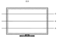
図8は、例えば全白画像のような最大点灯画像が入力された際の、液晶表示装置における水平方向の温度分布を示している。図8に示されるように、垂直方向に設定したA,B
,C各位置における温度は、LED光源等によって発生した熱が対流により液晶表示装置の上方に伝わるために、画面下部から上部にかけて温度が上昇する。また、A,B,Cのいずれも画面左右端で熱が中央部に対し相対的に低くなるが、これは、画面端部においいて空気層による放熱効果が得られる為である。
FIG. 8 shows a temperature distribution in the horizontal direction in the liquid crystal display device when a maximum lighting image such as an all-white image is input. As shown in FIG. 8, A and B set in the vertical direction
The temperature at each position rises from the lower part of the screen to the upper part because heat generated by the LED light source or the like is transmitted to the upper part of the liquid crystal display device by convection. In addition, in all of A, B, and C, the heat is relatively low at the left and right ends of the screen relative to the central portion because the heat radiation effect by the air layer is obtained at the end of the screen.
図9に、LED光源の温度特性の一例を示す。図示されるように、LED光源は、一般的にLEDの周囲温度の上昇に伴い発光輝度低下する温度特性を有している。 FIG. 9 shows an example of temperature characteristics of the LED light source. As shown in the drawing, the LED light source generally has a temperature characteristic in which the light emission luminance decreases as the ambient temperature of the LED increases.
そのため、略同輝度であるバックライトセルが同一制御値で点灯した際には、画面上部にあるバックライトセルほど温度の上昇と共に輝度が下がり、画面上端の輝度が相対的に下がる現象が生じる可能性がある。 For this reason, when backlight cells that have approximately the same brightness are lit at the same control value, the backlight cell at the top of the screen decreases in brightness as the temperature increases, and the brightness at the top of the screen may decrease relatively. There is sex.
そこで、本実施例では、上記問題の対策として、図10に示すように、相対的に輝度が低くなる画面左端部に位置するバックライトセル(101)と、温度が上昇する画面上端部に位置するバックライトセル(101)の光強度が強くなるようにシェーディング信号を生成するものである。すなわち、本実施例は、例えば図10に示されるように、領域L1〜L5にそれぞれ対応する前記シェーディング信号を下記の関係を満たすような値に設定し、図5に示されたシェーディング信号生成部(500)において生成するように構成している。 Therefore, in this embodiment, as a countermeasure for the above problem, as shown in FIG. 10, the backlight cell (101) located at the left end of the screen where the brightness is relatively low and the top end of the screen where the temperature rises are located. The shading signal is generated so that the light intensity of the backlight cell (101) to be increased. That is, in this embodiment, for example, as shown in FIG. 10, the shading signals corresponding to the regions L1 to L5 are set to values that satisfy the following relationship, and the shading signal generator shown in FIG. (500).
L1>L2>L3>L4>L5
シェーディング信号生成部(500)において、予め電源オンから時間経過による温度上昇に伴うLED光源の発光輝度の低下を補正するシェーディング信号のデータを予めROM等に格納しておき、電源オン時からの経過時間に応じてLUTを参照し、前記シェーディング信号を切り替えてもよい。
L1>L2>L3>L4> L5
In the shading signal generation unit (500), shading signal data for correcting a decrease in light emission luminance of the LED light source due to a temperature rise with the passage of time from power-on in advance is stored in a ROM or the like in advance, and the time since power-on The shading signal may be switched by referring to the LUT according to time.
このように、第3実施例は、高温となって光強度が低下する画面上部のバックライトセル(101)の光強度が強くしているので、導光板による輝度分布以外にも温度による輝度分布を補正しつつ、画面周辺部の輝度を画面中央部に比べ相対的に低い輝度分布を得ることででき、良好な画質を得ながらも消費電力を低減することができる。 As described above, in the third embodiment, the light intensity of the backlight cell (101) at the upper part of the screen where the light intensity decreases at a high temperature is increased. It is possible to obtain a luminance distribution with a relatively low luminance at the periphery of the screen as compared with the central portion of the screen while correcting the above, and it is possible to reduce power consumption while obtaining good image quality.
次に図11を参照しつつ本発明の第4実施例を説明する。この第4施例は、ユーザが選択する映像モードに応じて動的にシェーディング処理を制御するようにした点が、実施例1〜3と異なる。 Next, a fourth embodiment of the present invention will be described with reference to FIG. The fourth embodiment is different from the first to third embodiments in that the shading process is dynamically controlled according to the video mode selected by the user.
図11に、実施例4における回路ブロック図を示す。図11では、例えばユーザによるリモコン操作選択された映像モードに応じた制御信号が、マイコン(1100)からシェーディング信号生成部(500)に送出され、シェーディング信号生成部(500)において、シェーディング信号を制御する。 FIG. 11 is a circuit block diagram according to the fourth embodiment. In FIG. 11, for example, a control signal corresponding to the video mode selected by the user for remote control operation is sent from the microcomputer (1100) to the shading signal generation unit (500), and the shading signal generation unit (500) controls the shading signal. To do.
例えば、映画等の映像コンテンツを見る映像モードにおいては、ユーザの注視点が常に略中心領域にあるわけではなく、字幕等に代表されるように画面端部にユーザの注視点が移動することがある。そこで本実施例は、マイコン(1100)によって、シェーディング処理によって画面中央部の輝度よりも下げられた画面周辺部の輝度を、映画等を表示する場合は、ニュースなどの情報番組等の映像コンテンツを表示する場合に比べ相対的に高くなるようにシェーディング信号を制御するようにしている。例えば、映画等の表示する場合においては、画面中央部に対する画面周辺部の輝度を100%〜80%とし、情報番組等表示する場合においては、画面中央部に対する画面周辺部の輝度を80%〜65%とする等、マイコン(1100)は、表示するコンテンツに応じてシェーディング信号を切り替えるようにシェーディング信号生成部(500)を制御する。 For example, in a video mode in which video content such as a movie is viewed, the user's gaze point is not always in the substantially central area, and the user's gaze point may move to the screen edge as represented by subtitles or the like. is there. Therefore, in this embodiment, when the movie (such as a movie) is displayed by the microcomputer (1100), the brightness of the screen peripheral portion, which is lower than the brightness of the screen central portion by shading processing, is displayed. The shading signal is controlled so as to be relatively higher than in the case of display. For example, when displaying a movie or the like, the luminance of the screen periphery relative to the center of the screen is set to 100% to 80%. When displaying an information program or the like, the luminance of the screen periphery relative to the center of the screen is set to 80% to 80%. The microcomputer (1100) controls the shading signal generation unit (500) to switch the shading signal according to the content to be displayed, such as 65%.
画面上に映画が表示されるか情報番組が表示されるかは、例えばリモコンから送信されたリモコン信号がどの映像モードを示すかを識別することで判別することができる。すなわち、ユーザは、映画を視聴する場合は映像モードとして「シネマモード」を選択し、ニュースなどの情報番組を視聴する場合は「ノーマルモード」を選択する場合が多いと考えられる。よって、マイコン(1100)は、リモコンから送信された映像モードを選択するリモコン信号が「シネマモード」を示すことを識別した場合には、画面中央部に対する画面周辺部の輝度100%〜80%とするための指令をシェーディング信号生成部(500)に送信し、「ノーマルモード」を示すことを識別した場合には、画面中央部に対する
画面周辺部の輝度を80%〜65%とするための指令をシェーディング信号生成部(500)に送信する。
Whether a movie is displayed or an information program is displayed on the screen can be determined, for example, by identifying which video mode the remote control signal transmitted from the remote control indicates. That is, it is considered that the user often selects “cinema mode” as the video mode when viewing a movie, and selects “normal mode” when viewing an information program such as news. Therefore, when the microcomputer (1100) identifies that the remote control signal for selecting the video mode transmitted from the remote controller indicates “cinema mode”, the luminance of the screen peripheral portion relative to the screen central portion is 100% to 80%. When the command for transmitting the image is transmitted to the shading signal generation unit (500) and the “normal mode” is identified, the command for setting the luminance of the screen peripheral portion to 80% to 65% with respect to the screen central portion. Is transmitted to the shading signal generator (500).
また、表示される映像コンテンツの種類を、放送信号の含まれるEPG(電子番組ガイド)情報から識別するようにしてもよい。例えばユーザによりある番組が選択されたときに、該選択された番組のEPG情報を取得して選択された番組のジャンル(映画、ニュース、スポーツ等)を識別する。そして、この識別結果に基づき、上述と同様にシェーディング信号を制御する。 Further, the type of video content to be displayed may be identified from EPG (electronic program guide) information including a broadcast signal. For example, when a user selects a program, EPG information of the selected program is acquired to identify the genre (movie, news, sports, etc.) of the selected program. Based on the identification result, the shading signal is controlled in the same manner as described above.
このように本実施例では、表示する映像の内容に応じた輝度分布を得ると共に、消費電力を低減することができる As described above, in this embodiment, it is possible to obtain a luminance distribution according to the content of the video to be displayed and to reduce power consumption.
次に図12を参照しつつ本発明の第5実施例を説明する。この第5実施例は、画像信号に応じて動的にシェーディング信号を制御する点で、実施例1〜3と異なっている。 Next, a fifth embodiment of the present invention will be described with reference to FIG. The fifth embodiment is different from the first to third embodiments in that the shading signal is dynamically controlled according to the image signal.
図12に、実施例5における回路ブロック図を示す。図12に示された回路ブロックにおいて、画像信号処理部(502)は、受信した画像信号から映像の特徴量を検出し、この検出された特徴量に応じた映像特徴量信号(1200)をシェーディング信号生成部(
500)に送出する。シェーディング信号生成部(500)は、この映像特徴量信号(1200)に基づきシェーディング信号を制御する。シェーディング信号生成部(500)に送出される映像特徴量信号(1200)は、例えば一画面全体の映像信号の平均輝度(
APL)と、所定輝度以上の明るい物体が存在する位置(バックライトセル)の情報を含んでいる。
FIG. 12 is a circuit block diagram according to the fifth embodiment. In the circuit block shown in FIG. 12, the image signal processing unit (502) detects the feature amount of the video from the received image signal, and shades the video feature amount signal (1200) corresponding to the detected feature amount. Signal generator (
500). The shading signal generation unit (500) controls the shading signal based on the video feature amount signal (1200). The video feature value signal (1200) sent to the shading signal generation unit (500) is, for example, the average luminance (
APL) and information on the position (backlight cell) where a bright object having a predetermined luminance or higher exists.
例えば、全体的に暗い映像の画面端部に明るい物体が存在する場合、人間の注視点は明るい物体に向かうが、シェーディング処理により画面周辺部のバックライトセルの輝度を下げるとこの明るい物体の輝度も下がるため、明るい物体が見辛くなり、暗い映像がより暗く見えてしまう場合がある。 For example, if there is a bright object at the edge of the screen, which is generally dark, the human gaze point is toward the bright object, but if the brightness of the backlight cell around the screen is reduced by shading processing, the brightness of this bright object Therefore, it is difficult to see bright objects, and dark images may appear darker.
そこで本実施例では、常時シェーディング処理をするのではなく、映像特徴量信号(1200)に応じてシェーディング信号の強度を変更するようにしている。例えば、画像信号処理部(502)において、各バックライトセル(101)に対応する表示領域の部分における映像信号から輝度ヒストグラムを算出し、所定輝度以上(例えば200以上)の明るさを持つ度数が所定度数以上存在するバックライトセル(101)の位置を特定する
。これにより、どのバックライトセル(101)に明るい物体が存在するかを知ることができる。更に画像信号処理部(502)は、画面全体の画像の明るさを知るために一画像フレーム全体の平均輝度(APL)を検出する。これらの検出結果から、全体的に暗い映像の画面端部に明るい物体が存在する映像が入力されたことを検知することができる。
Therefore, in this embodiment, the intensity of the shading signal is changed in accordance with the video feature amount signal (1200) instead of always performing the shading process. For example, in the image signal processing unit (502), a luminance histogram is calculated from the video signal in the portion of the display area corresponding to each backlight cell (101), and the frequency having a brightness equal to or higher than a predetermined luminance (for example, 200 or higher) is obtained. The position of the backlight cell (101) existing at a predetermined frequency or more is specified. Thereby, it can be known in which backlight cell (101) the bright object exists. Further, the image signal processing unit (502) detects the average luminance (APL) of the entire image frame in order to know the brightness of the image of the entire screen. From these detection results, it is possible to detect that an image in which a bright object is present at the edge of the screen of an entirely dark image is input.
画像信号処理部(502)は、上記検出結果、すなわち明るい物体の位置情報とAPL情報を映像特徴量信号(1200)としてシェーディング信号生成部(500)に送出する。シェーディング信号生成部(500)は、この映像特徴量信号(1200)に含まれるAPLが所定値以下(例えば20以下)の場合であって、更に位置情報が、明るい物体が存在するバックライトセル(101)の位置が画面端部(図3のA及びE行と1列及び6列のバックライトセル)であることを示す場合には、画面端部の輝度低下を弱めるような制御信号を生成するか、もしくはシェーディング処理自身をしないように制御する。 The image signal processing unit (502) sends the detection result, that is, the position information of the bright object and the APL information to the shading signal generation unit (500) as a video feature amount signal (1200). The shading signal generation unit (500) is a backlight cell in which the APL included in the video feature value signal (1200) is a predetermined value or less (for example, 20 or less), and the position information further includes a bright object ( 101) indicates that the position is the edge of the screen (the A and E rows and the 1st and 6th columns of backlight cells in FIG. 3), a control signal is generated so as to reduce the luminance drop at the edge of the screen. Or control not to perform the shading process itself.
このように制御することで、画面端部に存在する明るい物体のピーク輝度が高くなり、見易くなるとともに暗い映像に画より暗く見えることを防止できる。また、制御の簡単化の為に、APLが低い画像に対しては、ピーク輝度を高く得るために、画面端部の輝度低下を弱めるような制御信号を生成するか、もしくはシェーディング処理自身をしないように制御してもよい。 By controlling in this way, the peak luminance of a bright object present at the edge of the screen is increased, making it easier to see and preventing dark images from appearing darker than the image. In order to simplify the control, in order to obtain a high peak luminance for an image with a low APL, a control signal that weakens the decrease in luminance at the edge of the screen is generated, or the shading process itself is not performed. You may control as follows.
次に図13を参照しつつ本発明の第6実施例を説明する。この第6実施例は、動的に電力制御を行うAPC(Auto Power Control)制御部(1300)を設け
、このAPC制御部(1300)により各バックライトセル(101)への制御信号を変更する点が、実施例1〜5と異なっている。
Next, a sixth embodiment of the present invention will be described with reference to FIG. In the sixth embodiment, an APC (Auto Power Control) control unit (1300) that dynamically controls power is provided, and the control signal to each backlight cell (101) is changed by the APC control unit (1300). The point differs from Examples 1-5.
図13に、実施例6における回路ブロック図を示す。図13に示された回路ブロックにおいて、バックライト制御部(503)は、シェーディング信号生成部(500)によって生成した各バックライトセル(101)への制御信号の重み付けをした後APC制御部(1300)に送出し、APC制御部(1300)では、この重み付けされた制御信号を変調してバックライト駆動部(505)に送出する。 FIG. 13 shows a circuit block diagram in the sixth embodiment. In the circuit block shown in FIG. 13, the backlight control unit (503) weights the control signal to each backlight cell (101) generated by the shading signal generation unit (500), and then performs the APC control unit (1300). The APC control unit (1300) modulates the weighted control signal and sends it to the backlight drive unit (505).
次に、APC制御部(1300)の動作を説明する。 Next, the operation of the APC control unit (1300) will be described.
APC制御部(1300)では、全てのバックライトセル(101)への制御信号を受け、この制御信号から液晶表示装置のバックライト装置で消費される電力を算出する。例えば、制御信号と消費電力の関係が比例関係にある場合、全てのバックライトセル(101)に対する制御信号の値を合計することにより、バックライト全体で消費する電力を算出することが可能となる。また、制御信号と消費電力の関係が比例関係にない場合においても、予め単一バックライトセルにおける制御信号と消費電力との関係をROM等に代表されるメモリに格納しておき、各バックライトセルへの制御信号に対応する消費電力をメモリから読み出して総和を演算することにより、バックライト装置全体の消費電力を算出することが可能となる。APC制御部(1300)は、その算出した消費電力値が一定の閾値を超えた場合、その閾値との差分に応じて、全てのバックライトセルへの制御信号(
シェーディング処理のための重み付けされた制御信号)に対し一律に1以下のゲインを乗算し、最大消費電力を制限する機能を有する。例えば、前記閾値を最大消費電力の90%と設定し、APC制御部(1300)で最大消費電力の95%の消費電力値が算出もられた場合、全てのバックライトセルへの制御信号に対し一律に90/95(≒0.947)倍し、最大消費電力を制限する。このようにして得られた各バックライトセルへの制御信号は、バックライト駆動部(505)へ送出され、バックライト駆動部(505)は各バックライトセル(101)を点灯制御する。
The APC control unit (1300) receives control signals to all the backlight cells (101), and calculates power consumed by the backlight device of the liquid crystal display device from the control signals. For example, when the relationship between the control signal and the power consumption is proportional, it is possible to calculate the power consumed by the entire backlight by summing the values of the control signals for all the backlight cells (101). . Even when the relationship between the control signal and the power consumption is not proportional, the relationship between the control signal and the power consumption in a single backlight cell is stored in advance in a memory such as a ROM, and each backlight By reading the power consumption corresponding to the control signal to the cell from the memory and calculating the sum, it is possible to calculate the power consumption of the entire backlight device. When the calculated power consumption value exceeds a certain threshold value, the APC control unit (1300) controls the control signals (all to the backlight cells) according to the difference from the threshold value.
The weighted control signal for shading processing) is uniformly multiplied by a gain of 1 or less to limit the maximum power consumption. For example, when the threshold value is set to 90% of the maximum power consumption and the power consumption value of 95% of the maximum power consumption is calculated by the APC control unit (1300), the control signal for all the backlight cells The maximum power consumption is limited by uniformly multiplying by 90/95 (≈0.947). The control signal to each backlight cell obtained in this way is sent to the backlight drive unit (505), and the backlight drive unit (505) controls lighting of each backlight cell (101).
また、図示しないが、前記閾値を、ユーザが選択する映像モードに応じて切り替えるようにしてもよい。また、APC制御部(1300)をシェーディング信号生成部(500
)の後段に配置することにより、シェーディング処理の有無、強度に影響を受けることなく、最大消費電力を制限することが可能となる。
Although not shown, the threshold value may be switched according to the video mode selected by the user. Further, the APC control unit (1300) is replaced with the shading signal generation unit (500).
It is possible to limit the maximum power consumption without being affected by the presence or absence of the shading process and the intensity.
このようにAPC制御部を用いることによりバックライトで消費される最大消費電力を制限することが可能となり、シェーディング処理による省電力の低減に加え、更なる消費電力の低減効果を高めることができる。 As described above, by using the APC control unit, it is possible to limit the maximum power consumption consumed by the backlight, and it is possible to further reduce the power consumption in addition to the power saving by the shading process.
尚、上記導光板(201)は、各バックライトセル(101)のそれぞれに個別に設けられてもよいが、複数のバックライトセル(101)間で導光板(201)を連結させても良い。すなわち、複数のバックライトセル(101)の導光板(201)を一つの一体化導光板で構成してもよい。この場合、一体化導光板には、バックライトセル(101)の境界と対応する部分に溝を形成しておくことが好ましい。
なお、上記実施例には、少なくとも次の内容が開示されている。
(1)
表示パネルと、該表示パネルに光を照射するためのバックライトを有する画像表示装置において、
前記バックライトからの光の強度を制御するバックライト制御部を有し、
前記バックライトは、光源と、該光源からの光が入射され、前記表示パネルに向けて出射する導光板とを有するエッジライト方式のバックライトセルを複数個マトリクス状に配列して構成され、
前記バックライト制御部は、前記バックライトセル毎に個別に光源を制御するものであって、画面周辺部に位置するバックライトセルからの光の強度を、画面略中央部に位置するバックライトセルからの光の強度よりも低くするように制御することを特徴とする画像表示装置。
(2)
上記「(1)」記載の画像表示装置において、
前記バックライト制御部は、更に、前記複数のバックライトセルのうち、前記バックライトの照射面の第1端部に隣接する光源を持つ前記バックライトセルの光強度を、該第1端部と対向する第2端部に隣接するバックライトセルの光強度よりも高くするように制御することを特徴とする画像表示装置。
(3)
上記「(1)」記載の画像表示装置において、
前記バックライト制御部は、前記画像表示装置の画面上部に位置する前記バックライトセルの光強度を、画面下部に位置する前記バックライトセルの光強度よりも相対的に高くなるように制御することを特徴とする画像表示装置。
(4)
上記「(1)」〜「(3)」のいずれかに記載の画像表示装置において、
ユーザの設定する映像表示モードに応じて、制御信号を送出するマイコンを有し、
前記マイコンの制御信号に応じて、前記バックライトセルの光強度を個別に制御することを特徴とする画像表示装置。
(5)
上記「(1)」〜「(4)」のいずれかに記載の画像表示装置において、
更に入力画像の特徴量を検出する画像信号処理部を有し、
前記バックライト制御部は、前記画像信号処理部で検出された前記入力画像の特徴量に応じて、前記画面周辺部の輝度低下度合いを制御することを特徴とする画像表示装置。
(6)
上記「(5)」記載の画像表示装置において、前記画像信号処理部で検出された前記入力画像の特徴量が、入力画像のAPLであることを特徴とする画像表示装置。
(7)
上記「(1)」〜「(5)」記載の画像表示装置において、
最大消費電力を制限するAPC制御部を有し、
前記APC制御部は、前記バックライト制御部にて決定された各バックライトセルへの制御信号に応じて消費電力を算出し、該算出された消費電力が所定値以上の場合に前記バックライトセルへの制御信号を変更すことを特徴とする画像表示装置。
(8)
表示パネルに光を照射するためのバックライト装置において、
光源と、該光源からの光が入射され、前記表示パネルに向けて出射する導光板とを有するエッジライト方式の複数のバックライトセルと、
前記バックライトセル毎に個別に光源を制御するためバックライト制御部とを備え、
前記バックライト制御部は、画面周辺部に位置するバックライトセルからの光の強度を、画面略中央部に位置するバックライトセルからの光の強度よりも低くするように制御することを特徴とするバックライト装置。
(9)
上記「(8)」記載のバックライト装置において、
前記バックライト制御部は、更に、前記複数のバックライトセルのうち、前記バックライトの照射面の第1端部に隣接する光源を持つ前記バックライトセルの光強度を、該第1端部と対向する第2端部に隣接するバックライトセルの光強度よりも高くするように制御することを特徴とするバックライト装置。
In addition, although the said light-guide plate (201) may be provided in each of each backlight cell (101) separately, you may connect a light-guide plate (201) between several backlight cells (101). . That is, you may comprise the light-guide plate (201) of a some backlight cell (101) with one integrated light-guide plate. In this case, the integrated light guide plate is preferably formed with a groove at a portion corresponding to the boundary of the backlight cell (101).
In the above-described embodiment, at least the following contents are disclosed.
(1)
In an image display device having a display panel and a backlight for irradiating the display panel with light,
A backlight control unit for controlling the intensity of light from the backlight;
The backlight is configured by arranging a plurality of edge light type backlight cells in a matrix form having a light source and a light guide plate that receives light from the light source and emits the light toward the display panel.
The backlight control unit individually controls the light source for each backlight cell, and the intensity of light from the backlight cell located in the peripheral portion of the screen is determined by the backlight cell located in the substantially central portion of the screen. An image display device that is controlled to be lower than the intensity of light from the image display device.
(2)
In the image display device described in the above “(1)”,
The backlight control unit further includes, among the plurality of backlight cells, the light intensity of the backlight cell having a light source adjacent to the first end of the irradiation surface of the backlight, and the first end. An image display device, characterized by being controlled to be higher than the light intensity of a backlight cell adjacent to the opposing second end.
(3)
In the image display device described in the above “(1)”,
The backlight control unit controls the light intensity of the backlight cell located at the upper part of the screen of the image display device to be relatively higher than the light intensity of the backlight cell located at the lower part of the screen. An image display device characterized by the above.
(4)
In the image display device according to any one of the above “(1)” to “(3)”,
According to the video display mode set by the user, it has a microcomputer that sends out control signals,
An image display device that individually controls light intensity of the backlight cell in accordance with a control signal of the microcomputer.
(5)
In the image display device according to any one of the above “(1)” to “(4)”,
Furthermore, it has an image signal processing unit that detects the feature amount of the input image,
The image display apparatus according to claim 1, wherein the backlight control unit controls a degree of luminance reduction of the peripheral portion of the screen according to a feature amount of the input image detected by the image signal processing unit.
(6)
The image display device according to the above (5), wherein the feature amount of the input image detected by the image signal processing unit is an APL of the input image.
(7)
In the image display device described in the above “(1)” to “(5)”,
An APC control unit that limits the maximum power consumption
The APC control unit calculates power consumption according to a control signal to each backlight cell determined by the backlight control unit, and when the calculated power consumption is a predetermined value or more, the backlight cell An image display device characterized by changing a control signal to
(8)
In the backlight device for irradiating the display panel with light,
A plurality of edge-light type backlight cells having a light source and a light guide plate to which light from the light source is incident and emitted toward the display panel;
A backlight control unit for controlling the light source individually for each backlight cell;
The backlight control unit controls the intensity of light from a backlight cell located in the periphery of the screen to be lower than the intensity of light from a backlight cell located in the approximate center of the screen. Backlight device to do.
(9)
In the backlight device described in “(8)” above,
The backlight control unit further includes, among the plurality of backlight cells, the light intensity of the backlight cell having a light source adjacent to the first end of the irradiation surface of the backlight, and the first end. A backlight device, wherein the backlight device is controlled to be higher than the light intensity of the backlight cell adjacent to the opposing second end.
この発明は、バックライトを複数の領域に分割して各領域を個別に制御できる液晶表示装置、例えば液晶テレビや携帯ディスプレイに適用できる。 The present invention can be applied to a liquid crystal display device that can divide a backlight into a plurality of regions and control each region individually, such as a liquid crystal television or a portable display.
100 表示領域
101 独立に制御可能なバックライト領域
200 LED光源
201 導光板
202 反射板
500 シェーディング信号生成部
501 画像フレーム受信部
502 画像信号処理部
503 バックライト制御部
504 画像信号補正部
505 バックライト駆動部
506 液晶制御部
507 H-ドライバ
508 V-ドライバ
509 液晶パネル
510 バックライト部
1100 マイコン
1200 映像特徴量信号
1300 APC制御部
DESCRIPTION OF
Claims (7)
第1の方向に光を出射するエッジライト方式の複数の光源と、該光源からの光が入射され、前記表示パネルに向けて出射する導光板とを有する複数のバックライトセルと、
前記バックライトセル毎に個別に光源を制御するバックライト制御部と、を備え、
前記バックライト制御部は、
前記表示パネルの周辺部に位置するバックライトセルからの光の強度を、前記表示パネルの略中央部に位置するバックライトセルからの光の強度よりも低くするように制御し、
前記第1の方向の上流にある前記表示パネルの第1端部に隣接するバックライトセルの光の強度を、前記第1端部と対向する第2端部に隣接するバックライトセルの光の強度よりも高くするように制御する、
ことを特徴とするバックライト装置。 In the backlight device for irradiating the display panel with light,
A plurality of backlight cells having a plurality of edge-light-type light sources that emit light in a first direction, and a light guide plate that receives light from the light sources and emits the light toward the display panel;
A backlight control unit for individually controlling the light source for each backlight cell,
The backlight control unit
Controlling the intensity of light from the backlight cell located in the periphery of the display panel to be lower than the intensity of light from the backlight cell located in the approximate center of the display panel;
The intensity of the light of the backlight cell adjacent to the first end of the display panel upstream of the first direction is the light intensity of the backlight cell adjacent to the second end facing the first end. controlled with high Kusuru so than strength,
A backlight device characterized by that.
ユーザの設定に応じて、制御信号を送出するマイコンを有し、前記マイコンの制御信号に応じて、前記バックライトセルの光強度についての前記画面略中央部と前記画面周辺部の差を変化させるよう制御することを特徴とするバックライト装置。 The backlight device according to claim 1,
According to a user's setting, it has a microcomputer which sends out a control signal, and changes the difference of the screen central part and the screen peripheral part about the light intensity of the backlight cell according to the control signal of the microcomputer A backlight device characterized by being controlled.
更に入力画像の特徴量を検出する画像信号処理部を有し、
前記バックライト制御部は、前記画像信号処理部で検出された前記入力画像の特徴量に応じて、前記画面周辺部の輝度低下度合いを制御することを特徴とするバックライト装置。 The backlight device according to claim 1 or 2,
Furthermore, it has an image signal processing unit that detects the feature amount of the input image,
The backlight device, wherein the backlight control unit controls a luminance reduction degree of the peripheral portion of the screen according to a feature amount of the input image detected by the image signal processing unit.
前記表示パネルの一部における映像信号が所定の光強度以上の明るさを持つ場合、前記バックライト制御部は、前記表示パネルの前記一部に位置する前記バックライトセルの光強度の前記低下を弱めるよう制御することを特徴とするバックライト装置。 The backlight device according to claim 1 or 2,
When a video signal in a part of the display panel has a brightness equal to or higher than a predetermined light intensity, the backlight control unit reduces the light intensity of the backlight cell located in the part of the display panel. A backlight device that is controlled to be weakened.
前記表示パネルの周辺部に位置するバックライトセルからの光の強度を、前記表示パネルの略中央部に位置するバックライトセルからの光の強度よりも低くするように制御し、
前記表示パネルの前記第1の方向の上流にある第1端部に隣接する光源を持つ前記バックライトセルの光強度を、前記第1端部と対向する第2端部に隣接するバックライトセルの光強度よりも高くするように制御する、
ことを特徴とするバックライト装置の制御方法。 A plurality of backlight cells each having a plurality of edge-light-type light sources that emit light in a first direction and a light guide plate that receives light from the light sources and emits the light toward the display panel; In the control method of the backlight device for irradiating light to the display panel by controlling the light source individually for each,
Controlling the intensity of light from the backlight cell located in the periphery of the display panel to be lower than the intensity of light from the backlight cell located in the approximate center of the display panel;
A backlight cell adjacent to a second end opposite to the first end, the light intensity of the backlight cell having a light source adjacent to the first end upstream of the display panel in the first direction. controlled with high Kusuru so than the light intensity,
A control method for a backlight device.
前記バックライト装置に配置された複数の領域ごとに所定数配置された複数のエッジライト方式の複数の光源と、
前記領域ごとに個別に光源を制御するバックライト制御部と、を備え、
前記バックライト制御部は、
前記バックライト装置の周辺部に位置する前記領域からの光の強度を、前記バックライト装置の略中央部に位置する前記領域からの光の強度よりも低くするように制御し、
前記光源が光を出射する方向の上流にある前記バックライト装置の第1端部に隣接する前記領域の光の強度を、前記第1端部と対向する第2端部に隣接する前記領域の光の強度よりも高くするように制御する、
ことを特徴とするバックライト装置。 In the backlight device,
A plurality of light sources of a plurality of edge light systems arranged in a predetermined number for each of a plurality of regions arranged in the backlight device;
A backlight control unit that individually controls the light source for each region,
The backlight control unit
Controlling the intensity of light from the region located in the peripheral part of the backlight device to be lower than the intensity of light from the region located in a substantially central part of the backlight device;
The intensity of light in the region adjacent to the first end of the backlight device upstream of the direction in which the light source emits light is set to be equal to that of the region adjacent to the second end facing the first end. controlled with high Kusuru so than the intensity of light,
A backlight device characterized by that.
前記表示パネルの上辺から下辺の方向に光を出射するエッジライト方式の複数の光源と、該光源からの光が入射され、前記表示パネルに向けて出射する導光板とを有する複数のバックライトセルと、
前記バックライトセル毎に個別に光源を制御するバックライト制御部と、を備え、
前記バックライト制御部は、
前記表示パネル周辺部に位置するバックライトセルからの光の強度を、前記表示パネルの略中央部に位置するバックライトセルからの光の強度よりも低くするように制御し、
前記表示パネルの上辺に隣接するバックライトセルの光の強度を、前記表示パネルの下辺に隣接するバックライトセルの光の強度よりも高くするように制御する、
ことを特徴とするバックライト装置。 In the backlight device for irradiating the display panel with light,
A plurality of backlight cells each having a plurality of edge light type light sources that emit light in the direction from the upper side to the lower side of the display panel, and a light guide plate that receives light from the light source and emits the light toward the display panel When,
A backlight control unit for individually controlling the light source for each backlight cell,
The backlight control unit
Controlling the intensity of light from the backlight cell located in the periphery of the display panel to be lower than the intensity of light from the backlight cell located in the approximate center of the display panel;
The intensity of light of a backlight cell which is adjacent to the upper side of the display panel, and controls the high Kusuru so than the intensity of light of a backlight cell which is adjacent to the lower side of the display panel,
A backlight device characterized by that.
Priority Applications (1)
| Application Number | Priority Date | Filing Date | Title |
|---|---|---|---|
| JP2011234584A JP5111652B2 (en) | 2011-10-26 | 2011-10-26 | Backlight device and control method of backlight device |
Applications Claiming Priority (1)
| Application Number | Priority Date | Filing Date | Title |
|---|---|---|---|
| JP2011234584A JP5111652B2 (en) | 2011-10-26 | 2011-10-26 | Backlight device and control method of backlight device |
Related Parent Applications (1)
| Application Number | Title | Priority Date | Filing Date |
|---|---|---|---|
| JP2010090028A Division JP5460435B2 (en) | 2010-04-09 | 2010-04-09 | Image display device and control method of image display device |
Publications (2)
| Publication Number | Publication Date |
|---|---|
| JP2012064588A JP2012064588A (en) | 2012-03-29 |
| JP5111652B2 true JP5111652B2 (en) | 2013-01-09 |
Family
ID=46060044
Family Applications (1)
| Application Number | Title | Priority Date | Filing Date |
|---|---|---|---|
| JP2011234584A Active JP5111652B2 (en) | 2011-10-26 | 2011-10-26 | Backlight device and control method of backlight device |
Country Status (1)
| Country | Link |
|---|---|
| JP (1) | JP5111652B2 (en) |
Families Citing this family (1)
| Publication number | Priority date | Publication date | Assignee | Title |
|---|---|---|---|---|
| CN111161684B (en) * | 2020-02-27 | 2024-02-27 | 京东方科技集团股份有限公司 | A backlight control method, device, backlight module and display device |
Family Cites Families (2)
| Publication number | Priority date | Publication date | Assignee | Title |
|---|---|---|---|---|
| KR100780205B1 (en) * | 2006-04-21 | 2007-11-27 | 삼성전기주식회사 | Backlight Unit for Liquid Crystal Display |
| JP2009042652A (en) * | 2007-08-10 | 2009-02-26 | Victor Co Of Japan Ltd | Liquid crystal display device and image display method thereof |
-
2011
- 2011-10-26 JP JP2011234584A patent/JP5111652B2/en active Active
Also Published As
| Publication number | Publication date |
|---|---|
| JP2012064588A (en) | 2012-03-29 |
Similar Documents
| Publication | Publication Date | Title |
|---|---|---|
| JP5460435B2 (en) | Image display device and control method of image display device | |
| US9922602B2 (en) | Display device and display method | |
| JP2010175913A (en) | Image display apparatus | |
| US6791566B1 (en) | Image display device | |
| US8736543B2 (en) | Liquid crystal display device with backlight | |
| JP5337757B2 (en) | Liquid crystal display device and backlight control method | |
| US8963826B2 (en) | Video display apparatus including brightness control based on ambient illuminance | |
| US20110057961A1 (en) | Liquid Crystal Display Device and Backlight Control Method | |
| US20100045694A1 (en) | Image Display Apparatus | |
| EP2357636B1 (en) | Display apparatus and control circuit of the same | |
| US20110285758A1 (en) | Image display apparatus | |
| US20140055510A1 (en) | Display apparatus and control method thereof | |
| US20110063338A1 (en) | Image display device and method of its operation | |
| JP2008299191A (en) | Image display device | |
| WO2012036058A1 (en) | Drive circuit, drive method, and display device | |
| JP5111652B2 (en) | Backlight device and control method of backlight device | |
| JP5002725B2 (en) | Backlight device and backlight control method | |
| JP2011118286A (en) | Liquid crystal display apparatus | |
| JP4894149B2 (en) | Liquid crystal display | |
| JP2011065022A (en) | Display device | |
| JP2012095127A (en) | Video display device and backlight control device |
Legal Events
| Date | Code | Title | Description |
|---|---|---|---|
| A131 | Notification of reasons for refusal |
Free format text: JAPANESE INTERMEDIATE CODE: A131 Effective date: 20120306 |
|
| A521 | Request for written amendment filed |
Free format text: JAPANESE INTERMEDIATE CODE: A523 Effective date: 20120427 |
|
| A131 | Notification of reasons for refusal |
Free format text: JAPANESE INTERMEDIATE CODE: A131 Effective date: 20120703 |
|
| A521 | Request for written amendment filed |
Free format text: JAPANESE INTERMEDIATE CODE: A523 Effective date: 20120824 |
|
| TRDD | Decision of grant or rejection written | ||
| A01 | Written decision to grant a patent or to grant a registration (utility model) |
Free format text: JAPANESE INTERMEDIATE CODE: A01 Effective date: 20120911 |
|
| A01 | Written decision to grant a patent or to grant a registration (utility model) |
Free format text: JAPANESE INTERMEDIATE CODE: A01 |
|
| A61 | First payment of annual fees (during grant procedure) |
Free format text: JAPANESE INTERMEDIATE CODE: A61 Effective date: 20121009 |
|
| FPAY | Renewal fee payment (event date is renewal date of database) |
Free format text: PAYMENT UNTIL: 20151019 Year of fee payment: 3 |
|
| R150 | Certificate of patent or registration of utility model |
Ref document number: 5111652 Country of ref document: JP Free format text: JAPANESE INTERMEDIATE CODE: R150 Free format text: JAPANESE INTERMEDIATE CODE: R150 |
|
| S111 | Request for change of ownership or part of ownership |
Free format text: JAPANESE INTERMEDIATE CODE: R313111 |
|
| R350 | Written notification of registration of transfer |
Free format text: JAPANESE INTERMEDIATE CODE: R350 |
|
| R250 | Receipt of annual fees |
Free format text: JAPANESE INTERMEDIATE CODE: R250 |
|
| R250 | Receipt of annual fees |
Free format text: JAPANESE INTERMEDIATE CODE: R250 |
|
| R250 | Receipt of annual fees |
Free format text: JAPANESE INTERMEDIATE CODE: R250 |
|
| R250 | Receipt of annual fees |
Free format text: JAPANESE INTERMEDIATE CODE: R250 |
|
| S111 | Request for change of ownership or part of ownership |
Free format text: JAPANESE INTERMEDIATE CODE: R313111 |
|
| R350 | Written notification of registration of transfer |
Free format text: JAPANESE INTERMEDIATE CODE: R350 |
|
| R250 | Receipt of annual fees |
Free format text: JAPANESE INTERMEDIATE CODE: R250 |
|
| R250 | Receipt of annual fees |
Free format text: JAPANESE INTERMEDIATE CODE: R250 |
|
| R250 | Receipt of annual fees |
Free format text: JAPANESE INTERMEDIATE CODE: R250 |
|
| R250 | Receipt of annual fees |
Free format text: JAPANESE INTERMEDIATE CODE: R250 |