JP5111418B2 - Cooker - Google Patents

Cooker Download PDF

Info

Publication number
JP5111418B2
JP5111418B2 JP2009062945A JP2009062945A JP5111418B2 JP 5111418 B2 JP5111418 B2 JP 5111418B2 JP 2009062945 A JP2009062945 A JP 2009062945A JP 2009062945 A JP2009062945 A JP 2009062945A JP 5111418 B2 JP5111418 B2 JP 5111418B2
Authority
JP
Japan
Prior art keywords
top plate
plate support
countertop
back surface
mounting hole
Prior art date
Legal status (The legal status is an assumption and is not a legal conclusion. Google has not performed a legal analysis and makes no representation as to the accuracy of the status listed.)
Expired - Fee Related
Application number
JP2009062945A
Other languages
Japanese (ja)
Other versions
JP2010216704A (en
Inventor
雅弘 小林
Current Assignee (The listed assignees may be inaccurate. Google has not performed a legal analysis and makes no representation or warranty as to the accuracy of the list.)
Mitsubishi Electric Home Appliance Co Ltd
Mitsubishi Electric Corp
Original Assignee
Mitsubishi Electric Home Appliance Co Ltd
Mitsubishi Electric Corp
Priority date (The priority date is an assumption and is not a legal conclusion. Google has not performed a legal analysis and makes no representation as to the accuracy of the date listed.)
Filing date
Publication date
Application filed by Mitsubishi Electric Home Appliance Co Ltd, Mitsubishi Electric Corp filed Critical Mitsubishi Electric Home Appliance Co Ltd
Priority to JP2009062945A priority Critical patent/JP5111418B2/en
Publication of JP2010216704A publication Critical patent/JP2010216704A/en
Application granted granted Critical
Publication of JP5111418B2 publication Critical patent/JP5111418B2/en
Expired - Fee Related legal-status Critical Current
Anticipated expiration legal-status Critical

Links

Images

Landscapes

  • Induction Heating Cooking Devices (AREA)

Description

本発明は、加熱調理器、詳しくはトッププレートを備えキッチンキャビネットのカウンタートップに組み込んで使用する加熱調理器に関するものである。   The present invention relates to a cooking device, and more particularly to a cooking device that includes a top plate and is used by being incorporated in a countertop of a kitchen cabinet.

従来、トッププレートを備えキッチンキャビネットのカウンタートップに組み込んで使用する加熱調理器において、トッププレートは枠体に接着され吊下げられた状態で保持されている構造のものが主流である。 2. Description of the Related Art Conventionally, in a heating cooker that includes a top plate and is used by being incorporated in a counter top of a kitchen cabinet, the top plate has a structure in which the top plate is held in a state of being attached to a frame and suspended.

この接着は、トッププレートと枠体を固着させる目的の他に、トッププレートと枠体の間からの水分等の浸入を防ぐという機能も併せ持っているが、トッププレート上に被調理物が収容された容器等の重量物が置かれることで、トッププレートと枠体の接着箇所に剥離方向の応力が加わり、経年の使用により接着箇所が剥離して水分等が浸入し、基板や電気部品が短絡し加熱調理器の安全性や使用者の安全を損なう恐れがあった。 In addition to the purpose of fixing the top plate and the frame, this bonding also has the function of preventing moisture and the like from entering between the top plate and the frame, but the food to be cooked is stored on the top plate. When a heavy object such as a container is placed, stress in the peeling direction is applied to the bonding location between the top plate and the frame, and the bonding location peels off over time, causing moisture to enter and short-circuiting the board and electrical components. However, there is a risk of impairing the safety of the cooker and the safety of the user.

そのため、トッププレートと枠体との接着剥離対策として、本体上端縁部とトッププレートの間に弾性部材を設け、トッププレートを支持するようにして、剥離方向の応力が加わらないように構成したものが開示されている(例えば、特許文献1参照)。 Therefore, as a measure against adhesion and peeling between the top plate and the frame, an elastic member is provided between the top edge of the main body and the top plate, and the top plate is supported so that stress in the peeling direction is not applied. Is disclosed (for example, see Patent Document 1).

また、金属性の支持体によりトッププレートを支持するようにして、剥離方向の応力が加わらないように構成したものも開示されている(例えば、特許文献2参照)。 In addition, a configuration in which a top plate is supported by a metallic support so that stress in the peeling direction is not applied is also disclosed (for example, see Patent Document 2).

特開2007−003016号公報(第4頁、図2)JP 2007-003016 A (Page 4, FIG. 2)

特開2005−265211号公報(第3頁、図3)Japanese Patent Laying-Open No. 2005-265221 (page 3, FIG. 3)

しかしながら、特許文献1に開示された加熱調理器では、トッププレートと本体上端縁部の間に弾性体を配設しトッププレートを支持し、剥離対策としているが、弾性体が軟らかいとトッププレートに被調理物を収容した容器などの荷重が加えられた時に、弾性体が圧縮されてトッププレートが沈み込みトッププレートと枠体の接着箇所に剥離方向の応力が加わり、剥離対策としての効果が損なわれてしまう。   However, in the cooking device disclosed in Patent Document 1, an elastic body is disposed between the top plate and the upper end edge of the main body to support the top plate, and as a countermeasure against peeling, but if the elastic body is soft, the top plate When a load such as a container that contains the food is applied, the elastic body is compressed and the top plate sinks, stress in the peeling direction is applied to the bonding area between the top plate and the frame, and the effect as a countermeasure against peeling is impaired. It will be.

そのため、弾性体の圧縮度を上げて硬度を増したり、弾性体自体の硬度を上げたりしなければならないが、弾性体の硬度を上げることでトッププレートの剥離対策には効果を得られるが、逆にトッププレートの支持に柔軟性が無くなり、輸送時やカウンタートップに組み込む時に、トッププレートに例えば輸送時の振動で本体が突き上げられた時の衝撃力や、組み込む時に本体をキッチンキャビネットや壁にぶつけたりした時の衝撃力のような外部からの力(以下外部応力と記す)が直接加わる場合があり破損する恐れがある、という問題があった。   Therefore, it is necessary to increase the degree of compression of the elastic body to increase the hardness, or to increase the hardness of the elastic body itself, but by increasing the hardness of the elastic body, an effect can be obtained as a countermeasure against peeling of the top plate, On the other hand, the support of the top plate becomes inflexible, and when it is transported or installed in the countertop, for example, the impact force when the main body is pushed up by vibration during transport, for example, or the main body is attached to the kitchen cabinet or wall There was a problem that an external force (hereinafter referred to as an external stress) such as an impact force at the time of impact may be directly applied and there is a risk of damage.

また、特許文献2に開示された加熱調理器では、トッププレートを金属性の支持体で受け、剥離対策としているが、特許文献1に開示された加熱調理器の、弾性体の硬度を上げた時と同様、トッププレートの支持に柔軟性が無く、輸送時やカウンタートップに組み込む時に、トッププレートに外部応力が直接加わる場合があり破損する恐れがある、という問題があった。   Moreover, in the heating cooker disclosed in Patent Document 2, the top plate is received by a metallic support to prevent peeling, but the hardness of the elastic body of the heating cooker disclosed in Patent Document 1 is increased. As in the past, there was a problem that the support of the top plate was not flexible, and there was a possibility that external stress might be directly applied to the top plate when it was transported or incorporated in the countertop, which could cause damage.

本発明は、かかる課題を解決するためのもので、輸送時やカウンタートップに組み込む時にトッププレートを破損する恐れが無く、更に枠体とトッププレートの接着箇所に剥離が発生しない加熱調理器を提供することを目的とする。   The present invention is to solve such a problem, and provides a cooking device in which there is no risk of damaging the top plate during transportation or incorporation into a countertop, and further, no peeling occurs at the bonded portion between the frame and the top plate. The purpose is to do.

本発明の加熱調理器は、キッチンキャビネットのカウンタートップに設けた開口に、落とし込むようにして組み込む本体と、本体天面に配設され、被調理物を収容した容器を載置可能なトッププレート及びトッププレートの周囲を覆うロ字状の枠体からなり、トッププレートの容器載置面と枠体の内周裏面とで接着してなる、カウンタートップの開口より大きい天板部と、本体上端に設けられ、カウンタートップの開口よりも外側へ延設した縁部と、組み込みが完了すると上端部がトッププレート裏面に当接し、下端部がカウンタートップ上面に当接し、トッププレート裏面とカウンタートップ上面間で挟持され、トッププレートを支持するトッププレート支持体と、を備え、トッププレート支持体は、縁部に設けられた取付穴に挿通されて、カウンタートップの開口に組み込む前には、トッププレート裏面に上端部が当接しない位置で可動自在に保持されているようにしたものである。   The heating cooker of the present invention includes a main body that is incorporated in a countertop of a kitchen cabinet so as to drop, a top plate that is disposed on the top surface of the main body and on which a container that accommodates an object to be cooked can be placed; A top plate that is larger than the opening of the countertop, and is attached to the container mounting surface of the top plate and the inner peripheral back surface of the frame. The edge that is provided and extends outward from the opening of the countertop, and when the assembly is completed, the upper end contacts the back of the top plate, the lower end contacts the top of the counter top, and between the back of the top plate and the top of the counter top And a top plate support that supports the top plate, and the top plate support is inserted into a mounting hole provided at an edge. Prior to incorporation into the opening of the countertop is obtained as being movably held in a position where the upper end portion does not abut the top plate rear surface.

本発明の加熱調理器においては、輸送時やカウンタートップへ組み込む前にはトッププレートを支持していないので、トッププレートへの外部応力がかからないため、輸送時やカウンタートップに組み込む時にトッププレートを破損することがない安全な加熱調理器を提供できる、という効果がある。   In the cooking device of the present invention, the top plate is not supported during transportation or before being incorporated into the counter top, so that external stress is not applied to the top plate, so the top plate is damaged during transportation or incorporation into the counter top. There is an effect that it is possible to provide a safe heating cooker that does not need to be done.

本発明の実施の形態1における加熱調理器の全体構成を示す斜視図。The perspective view which shows the whole structure of the heating cooker in Embodiment 1 of this invention. 本発明の実施の形態1における加熱調理器の天板部を取り外した状態の全体構 成を示す斜視図。The perspective view which shows the whole structure of the state which removed the top-plate part of the heating cooker in Embodiment 1 of this invention. 本発明の実施の形態1における加熱調理器のキッチンキャビネットのカウンタートップへの組み込み概念図。Fig. 3 is a conceptual diagram of incorporation of the heating cooker in the kitchen cabinet countertop according to the first embodiment of the present invention. 本発明の実施の形態1における加熱調理器をキッチンキャビネットのカウンタートップに組み込んだ状態の斜視図。The perspective view of the state which integrated the heating cooker in Embodiment 1 of this invention in the countertop of a kitchen cabinet. 本発明の実施の形態1における加熱調理器のトッププレート支持体と取付穴を示す部分斜視図。The partial perspective view which shows the top plate support body and attachment hole of the heating cooker in Embodiment 1 of this invention. 本発明の実施の形態1における加熱調理器の組み込み前のトッププレート支持体の状態を示す断面図。Sectional drawing which shows the state of the top plate support body before incorporation of the heating cooker in Embodiment 1 of this invention. 本発明の実施の形態1における加熱調理器の組み込み途中のトッププレート支持体の状態を示す断面図。Sectional drawing which shows the state of the top plate support body in the middle of the assembly of the heating cooker in Embodiment 1 of this invention. 本発明の実施の形態1における加熱調理器の組み込み完了時点のトッププレート支持体の状態を示す断面図。Sectional drawing which shows the state of the top plate support body at the time of completion of the assembly of the heating cooker in Embodiment 1 of this invention. 本発明の実施の形態2における加熱調理器のトッププレート支持体と切欠きを示す部分斜視図。The partial perspective view which shows the top plate support body and notch of the heating cooker in Embodiment 2 of this invention. 本発明の実施の形態2における加熱調理器の組み込み前のトッププレート支持体の状態を示す断面図。Sectional drawing which shows the state of the top plate support body before incorporation of the heating cooker in Embodiment 2 of this invention. 本発明の実施の形態3における加熱調理器の組み込み前のトッププレート支持体とガイド部を設けた取付穴を示す断面図。Sectional drawing which shows the attachment hole which provided the top plate support body and guide part before the incorporation of the heating cooker in Embodiment 3 of this invention. 本発明の実施の形態4における加熱調理器の組み込み前の抜け防止部を備えたトッププレート支持体と取付穴を示す断面図。Sectional drawing which shows the top plate support body and attachment hole provided with the drop prevention part before the incorporation of the heating cooker in Embodiment 4 of this invention. 本発明の実施の形態5における加熱調理器のトッププレート支持体と保持片を示す部分斜視図。The partial perspective view which shows the top plate support body and holding piece of the heating cooker in Embodiment 5 of this invention. 本発明の実施の形態5における加熱調理器の組み込み前のトッププレート支持体と保持片を示す断面図。Sectional drawing which shows the top plate support body and holding piece before the incorporation of the heating cooker in Embodiment 5 of this invention. 本発明の実施の形態6における加熱調理器の組み込み前の抜け防止構造を備えたトッププレート支持体と保持片を示す断面図。Sectional drawing which shows the top plate support body and holding piece which were provided with the removal prevention structure before the incorporation of the heating cooker in Embodiment 6 of this invention. 本発明の実施の形態7における加熱調理器のトッププレート支持体の状態を示す部分斜視図。The fragmentary perspective view which shows the state of the top plate support body of the heating cooker in Embodiment 7 of this invention. 本発明の実施の形態7における加熱調理器の組み込み前のトッププレート支持体の状態を示す断面図。Sectional drawing which shows the state of the top plate support body before the integration of the heating cooker in Embodiment 7 of this invention. 本発明の実施の形態7における加熱調理器の組み込み途中のトッププレート支持体の状態を示す断面図。Sectional drawing which shows the state of the top plate support body in the middle of the assembly of the heating cooker in Embodiment 7 of this invention. 本発明の実施の形態7における加熱調理器の組み込み完了時点のトッププレート支持体の状態を示す断面図。Sectional drawing which shows the state of the top plate support body at the time of completion of the assembly of the heating cooker in Embodiment 7 of this invention.

実施の形態1.
図1は本発明の実施の形態1における加熱調理器の全体構成を示す斜視図、図2は本発明の実施の形態1における加熱調理器の天板部を取り外した状態の全体構成を示す斜視図、図3は本発明の実施の形態1における加熱調理器のキッチンキャビネットのカウンタートップへの組み込み概念図、図4は本発明の実施の形態1における加熱調理器をキッチンキャビネットのカウンタートップに組み込んだ状態の斜視図、図5は本発明の実施の形態1における加熱調理器のトッププレート支持体と取付穴を示す部分斜視図、図6は本発明の実施の形態1における加熱調理器の組み込み前のトッププレート支持体の状態を示す断面図、図7は本発明の実施の形態1における加熱調理器の組み込み途中のトッププレート支持体の状態を示す断面図、図8は本発明の実施の形態1における加熱調理器の組み込み完了時点のトッププレート支持体の状態を示す断面図である。
Embodiment 1 FIG.
FIG. 1 is a perspective view showing the overall configuration of the heating cooker according to Embodiment 1 of the present invention, and FIG. 2 is a perspective view showing the overall configuration of the heating cooker according to Embodiment 1 of the present invention with the top plate portion removed. FIG. 3 is a conceptual diagram of incorporating the heating cooker in the kitchen cabinet countertop according to the first embodiment of the present invention, and FIG. 4 is a diagram illustrating the incorporation of the heating cooker according to the first embodiment of the present invention into the countertop of the kitchen cabinet. FIG. 5 is a partial perspective view showing the top plate support and mounting holes of the heating cooker according to the first embodiment of the present invention, and FIG. 6 is the incorporation of the heating cooker according to the first embodiment of the present invention. Sectional drawing which shows the state of the front top plate support body, FIG. 7 is sectional drawing which shows the state of the top plate support body in the middle of the assembly of the heating cooker in Embodiment 1 of this invention, FIG. Is a sectional view showing a state of a top plate support incorporation completion of the heating cooker in the first embodiment of the present invention.

なお、それぞれの図において、同じ部分または相当する部分には同じ符号を付し、一部の説明を省略する。また、複数の部材であって、符号に「a、b、あるいはc等」を付記するものについて、共通する内容を説明する際には、符号に付した「a、b、あるいはc等」を削除して、その一方の部材について説明する。 In the respective drawings, the same or corresponding parts are denoted by the same reference numerals, and a part of the description is omitted. In addition, when explaining the common contents of a plurality of members that have “a, b, or c” added to the reference numeral, add “a, b, or c” added to the reference numeral. It deletes and the one member is demonstrated.

図1に示すように、本発明の実施の形態1における加熱調理器は、加熱調理器101の本体1の天面に、被調理物を収容した容器2を載置可能な非磁性体、例えば結晶化ガラスやセラミックからなるトッププレート3と、例えばステンレス等の金属からなるトッププレート3の周囲を覆うロ字状の枠体4で構成された天板部5を備えている。それから、天板部5に各種の操作入力を行う天面操作手段6を備え、電源の入り切りや各種の操作入力を行う前面操作手段7と、焼き物調理を行うためのグリル庫8を備えている。なお、操作手段の位置や数は、本発明においては関係がないので、操作手段を1箇所にまとめる等、構成は適宜変更が可能である。   As shown in FIG. 1, the cooking device according to Embodiment 1 of the present invention is a non-magnetic material capable of placing a container 2 containing an object to be cooked on the top surface of the main body 1 of the cooking device 101, for example, A top plate portion 5 is provided that includes a top plate 3 made of crystallized glass or ceramic and a frame 4 having a square shape that covers the periphery of the top plate 3 made of metal such as stainless steel. Then, the top panel unit 5 is provided with a top surface operating means 6 for performing various operation inputs, a front surface operating means 7 for performing on / off of the power source and various operation inputs, and a grill box 8 for performing cooking of the pottery. . Note that the position and number of the operation means are not relevant in the present invention, and the configuration can be changed as appropriate, for example, the operation means are combined in one place.

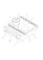
また、図2に示すように、天板部5の下方には複数の加熱手段、加熱手段a9、加熱手段b10、加熱手段c11が配設されている。加熱手段の方式としては、誘導加熱コイルからなる電磁誘導加熱方式や、ニクロム線ヒータ、ハロゲンヒータ、ラジエントヒータ等の輻射によって加熱される輻射型電気加熱等の方式がある。なお、加熱手段の方式や、加熱手段の数および加熱手段の組合せは、本発明においては関係がないので、適宜選択が可能である。   As shown in FIG. 2, a plurality of heating means, heating means a9, heating means b10, and heating means c11 are arranged below the top plate portion 5. As a method of the heating means, there are a method such as an electromagnetic induction heating method composed of an induction heating coil, and a radiation type electric heating method that is heated by radiation of a nichrome wire heater, a halogen heater, a radiant heater or the like. Note that the method of the heating means, the number of heating means, and the combination of the heating means are not relevant in the present invention, and can be appropriately selected.

それから、CPUやその他電子部品を搭載した制御基板等からなり天面操作手段6と前面操作手段7からの操作入力により加熱調理器101を制御する制御手段12が配設され、種々の情報を表示の形で報知する報知手段a13、報知手段b14、報知手段c15を備え、本体1の上端部に縁部16a、16b(以下まとめて縁部16と記す)が配設されている。なお、報知手段の数や配置は、本発明においては関係がないので、報知手段を1箇所にまとめる等、構成は適宜変更が可能である。 Then, a control means 12 comprising a control board or the like on which a CPU and other electronic components are mounted and controlling the heating cooker 101 by operation inputs from the top surface operation means 6 and the front surface operation means 7 is arranged to display various information. The notification means a13, the notification means b14, and the notification means c15 are provided, and edge portions 16a and 16b (hereinafter collectively referred to as the edge portion 16) are disposed at the upper end portion of the main body 1. In addition, since the number and arrangement | positioning of alerting | reporting means have no relationship in this invention, a structure can be suitably changed, such as putting together a alerting | reporting means in one place.

次に、図3に基き加熱調理器101の組み込み方法の概念ついて説明する。図3に示すようにキッチンキャビネット201の上部に、カウンタートップ202が配設され、カウンタートップ202には開口203が設けられている。加熱調理器101は、本体1を、まず開口203に通し、支点Aの点を軸に回転方向Bの方向に回転させながら落とし込んでいく。   Next, the concept of the method for incorporating the heating cooker 101 will be described with reference to FIG. As shown in FIG. 3, a counter top 202 is disposed on an upper portion of the kitchen cabinet 201, and an opening 203 is provided in the counter top 202. The heating cooker 101 drops the main body 1 through the opening 203 while rotating it in the direction of the rotation direction B around the fulcrum A.

この時、天板部5は、開口203よりも大きいので、カウンタートップ202に天板部5が載るようになっている。組み込みが完了すると、図4に示すように、カウンタートップ202に加熱調理器101が収まり、使用可能な状態となる。 At this time, since the top plate portion 5 is larger than the opening 203, the top plate portion 5 is placed on the counter top 202. When the assembly is completed, as shown in FIG. 4, the heating cooker 101 is housed in the countertop 202 and is ready for use.

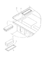
次に図5に基いて、縁部16の周辺部を詳しく説明すると、図5に示すように、縁部16に取付穴18が設けられている。この取付穴18に、トップトッププレート支持体17が挿通されるようになっている。トップトッププレート支持体17は、摺動部19、下端部20、上端部21からなり、トップトッププレート支持体17の摺動部19を、取付穴18に摺動自在に保持する構成となっている。   Next, the peripheral portion of the edge portion 16 will be described in detail with reference to FIG. 5. As shown in FIG. 5, a mounting hole 18 is provided in the edge portion 16. The top top plate support 17 is inserted into the mounting hole 18. The top top plate support 17 includes a sliding portion 19, a lower end portion 20, and an upper end portion 21, and the sliding portion 19 of the top top plate support 17 is slidably held in the mounting hole 18. Yes.

ここで、トップトッププレート支持体17の上端部21は、摺動部19の断面積及び、取付穴18よりも大きくしてあるので、取付穴18からトップトッププレート支持体17が落下することはない。 Here, since the upper end portion 21 of the top top plate support 17 is larger than the cross-sectional area of the sliding portion 19 and the mounting hole 18, the top top plate support 17 is not dropped from the mounting hole 18. Absent.

以上のように構成された本発明の実施の形態1における加熱調理器について、図6から図8により動作を説明する。   The operation of the cooking device according to the first embodiment of the present invention configured as described above will be described with reference to FIGS.

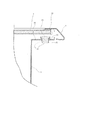
図6に示すように、トッププレート3は、トッププレート3の容器載置面と枠体4の内周裏面で、例えばシリコンRTVのような接着剤22によって、枠体4に吊下げられた状態で接着保持されている。この時はまだ組み込み前なので、トッププレート支持体17は、縁部16に設けられた取付穴18に挿通され、懸吊状態で保持されていて、トッププレート3の裏面とは当接していない。   As shown in FIG. 6, the top plate 3 is suspended from the frame 4 by an adhesive 22 such as silicon RTV on the container placement surface of the top plate 3 and the inner peripheral back surface of the frame 4. It is held by bonding. At this time, since it is not yet assembled, the top plate support 17 is inserted into the mounting hole 18 provided in the edge portion 16 and held in a suspended state, and is not in contact with the back surface of the top plate 3.

図3で示したように組み込み作業を開始すると、図7に示すように、カウンタートップ202の上面と、トッププレート支持体17の下端部20が当接し押上げられ、取付穴18を摺動部19が摺動し、トッププレート3の裏面にトッププレート支持体17の上端部21が接近していく。   When the assembling work is started as shown in FIG. 3, the upper surface of the countertop 202 and the lower end portion 20 of the top plate support 17 are brought into contact and pushed up as shown in FIG. 19 slides, and the upper end 21 of the top plate support 17 approaches the back surface of the top plate 3.

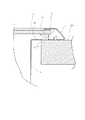
組み込み作業が完了すると、図8に示すように、カウンタートップ202の上面と縁部16のカウンタートップ202の上面に対向する面が当接し、加熱調理器101が保持される。また、カウンタートップ202の上面に押上げられたトッププレート支持体17の上端部21が、トッププレート3の裏面で枠体4と接着保持されている近傍に当接する。これにより、トッププレート支持体17によるトッププレート3の支持状態が完成する。この時、縁部16のカウンタートップ202の上面に対向する面とトッププレート支持体17の下端部20はほぼ同一高さとなるよう設定されている。   When the assembling work is completed, as shown in FIG. 8, the upper surface of the counter top 202 and the surface of the edge 16 facing the upper surface of the counter top 202 come into contact with each other, and the heating cooker 101 is held. Further, the upper end portion 21 of the top plate support 17 pushed up on the upper surface of the countertop 202 abuts on the back surface of the top plate 3 in the vicinity of being bonded and held to the frame body 4. Thereby, the support state of the top plate 3 by the top plate support 17 is completed. At this time, the surface of the edge portion 16 facing the upper surface of the countertop 202 and the lower end portion 20 of the top plate support 17 are set to have substantially the same height.

以上の動作により、加熱調理器101の輸送時やカウンタートップ202へ組み込み前には、トッププレート支持体17がトッププレート3を支持していないので、トッププレート3への外部応力がかからないため、輸送時やカウンタートップ202に組み込む時にトッププレート3を破損することがない安全な加熱調理器101を提供することができる。   With the above operation, since the top plate support 17 does not support the top plate 3 when the cooking device 101 is transported or before being incorporated into the countertop 202, no external stress is applied to the top plate 3. It is possible to provide a safe heating cooker 101 that does not break the top plate 3 at the time or when it is incorporated in the countertop 202.

また、加熱調理器101をカウンタートップ202に組み込むだけで、トッププレート支持体17が、カウンタートップ202の上面とトッププレート3の裏面間で挟持されトッププレート3を支持することができるので、接着剤の剥離が発生せず、基板や電気部品への水分等の浸入を防止することができ、加熱調理器101を使用する使用者の安全を確保することができる。 In addition, the top plate support 17 can be sandwiched between the upper surface of the counter top 202 and the back surface of the top plate 3 and can support the top plate 3 simply by incorporating the heating cooker 101 into the counter top 202. Is not generated, moisture and the like can be prevented from entering the substrate and electrical components, and the safety of the user who uses the cooking device 101 can be ensured.

さらに、本体1に従来からある縁部16に小規模な改造で、トッププレート支持体17を取付でき、カウンタートップ202へ組み込む時には、特別な工具等を必要としないため、従来の組み込み作業と同じ作業で組み込みができるので、コストアップを抑えることができ、カウンタートップには何ら手を加える必要がないので、従来の加熱調理器からの入れ換えが容易にできる。 Further, the top plate support 17 can be attached to the main body 1 by a small modification to the conventional edge 16 and no special tool or the like is required when assembling into the countertop 202, so the same as the conventional assembling work. Since it can be built in by work, it is possible to suppress the cost increase, and it is not necessary to modify the counter top at all, so it is possible to easily replace the conventional cooking device.

実施の形態2.
図9は本発明の実施の形態2における加熱調理器のトッププレート支持体と切欠きを示す部分斜視図、図10は本発明の実施の形態2における加熱調理器の組み込み前のトッププレート支持体の状態を示す断面図である。なお、実施の形態2においては、図1から図4で示した実施の形態1の構成を使用するものであり、よってここでの説明は省略する。
Embodiment 2. FIG.
FIG. 9 is a partial perspective view showing the top plate support and the cutout of the heating cooker according to the second embodiment of the present invention, and FIG. 10 is the top plate support before assembling the heating cooker according to the second embodiment of the present invention. It is sectional drawing which shows this state. In the second embodiment, the configuration of the first embodiment shown in FIGS. 1 to 4 is used, and thus the description thereof is omitted here.

図9に基いて、縁部16の周辺部を詳しく説明すると、図9に示すように、縁部16に切欠き37が設けられている。この切欠き37に、下端部38、摺動部19、上端部39からなるトップトッププレート支持体36が摺動可能に嵌合する構成となっている。   The peripheral portion of the edge portion 16 will be described in detail with reference to FIG. 9. As shown in FIG. 9, a notch 37 is provided in the edge portion 16. A top-top plate support 36 including a lower end portion 38, a sliding portion 19, and an upper end portion 39 is slidably fitted into the notch 37.

以上のように構成された本発明の実施の形態2における加熱調理器について、図10により動作を説明する。   The operation of the cooking device according to the second embodiment of the present invention configured as described above will be described with reference to FIG.

図10に示すように、トッププレート3は、トッププレート3の容器載置面と枠体4の内周裏面で、例えばシリコンRTVのような接着剤22によって、枠体4に吊下げられた状態で接着保持されている。この時はまだ組み込み前なので、トッププレート支持体36は、縁部16に設けられた切欠き37に嵌合され、懸吊状態で保持されていて、トッププレート3の裏面とは当接していない。   As shown in FIG. 10, the top plate 3 is suspended from the frame 4 by an adhesive 22 such as silicon RTV on the container placement surface of the top plate 3 and the inner peripheral back surface of the frame 4. It is held by bonding. At this time, since it is not yet assembled, the top plate support 36 is fitted in a notch 37 provided in the edge 16 and is held in a suspended state, and is not in contact with the back surface of the top plate 3. .

以上の構成により、加熱調理器101の輸送時やカウンタートップ202へ組み込み前には、トッププレート支持体36がトッププレート3を支持していないので、トッププレート3への外部応力がかからないため、輸送時やカウンタートップ202に組み込む時にトッププレート3を破損することがない安全な加熱調理器101を提供することができる。   With the above configuration, since the top plate support 36 does not support the top plate 3 when the cooking device 101 is transported or before being incorporated into the countertop 202, the external stress on the top plate 3 is not applied. It is possible to provide a safe heating cooker 101 that does not break the top plate 3 at the time or when it is incorporated in the countertop 202.

また、加熱調理器101をカウンタートップ202に組み込むだけで、トッププレート支持体36が、カウンタートップ202の上面とトッププレート3の裏面間で挟持されトッププレート3を支持することができるので、接着剤の剥離が発生せず、基板や電気部品への水分等の浸入を防止することができ、加熱調理器101を使用する使用者の安全を確保することができる。 Moreover, the top plate support 36 can be sandwiched between the upper surface of the counter top 202 and the back surface of the top plate 3 and can support the top plate 3 simply by incorporating the heating cooker 101 into the counter top 202. Is not generated, moisture and the like can be prevented from entering the substrate and electrical components, and the safety of the user who uses the cooking device 101 can be ensured.

さらに、本体1に従来からある縁部16に小規模な改造で、トッププレート支持体36を取付でき、カウンタートップ202へ組み込む時には、特別な工具等を必要としないため、従来の組み込み作業と同じ作業で組み込みができるので、コストアップを抑えることができ、カウンタートップには何ら手を加える必要がないので、従来の加熱調理器からの入れ換えが容易にできる。 Further, the top plate support 36 can be attached to the main body 1 by a small modification to the conventional edge 16, and no special tool or the like is required when assembling into the countertop 202. Since it can be built in by work, it is possible to suppress the cost increase, and it is not necessary to modify the counter top at all, so it is possible to easily replace the conventional cooking device.

実施の形態3.
図11は本発明の実施の形態3における加熱調理器の組み込み前のトッププレート支持体とガイド部を設けた取付穴を示す断面図である。なお、実施の形態3においては、図1から図4で示した実施の形態1の構成を使用するものであり、よってここでの説明は省略する。
Embodiment 3 FIG.
FIG. 11 is a cross-sectional view showing a mounting hole provided with a top plate support and a guide portion before the heating cooker is assembled in Embodiment 3 of the present invention. In the third embodiment, the configuration of the first embodiment shown in FIGS. 1 to 4 is used, and thus the description thereof is omitted here.

図11に示すように、取付穴18の外周にガイド部23が設けられている。ガイド部23はトッププレート支持体17の摺動を安定させるためのもので、トッププレート3の裏面側に向けて延設してあり、トッププレート支持体17の摺動部19と取付穴18との摺動面積が大きくなっている。
また、この状態は組み込み前であるため、トッププレート支持体17は、懸吊状態で保持されている。
As shown in FIG. 11, a guide portion 23 is provided on the outer periphery of the mounting hole 18. The guide portion 23 is for stabilizing the sliding of the top plate support 17 and extends toward the back side of the top plate 3, and the sliding portion 19 and the mounting hole 18 of the top plate support 17 The sliding area is large.
Since this state is before assembly, the top plate support 17 is held in a suspended state.

実施の形態1では取付穴18を単純な抜き穴形状としたが、上記のように取付穴18の外周にガイド部23を設けて、トッププレート支持体17の摺動部19と取付穴18との摺動面積が大きくなっているので、トッププレート支持体17が摺動する際のふらつき等を抑えることができ、トッププレート支持体17の摺動動作をより確実にすることができ、トッププレート3の支持を安定させることができる。   In Embodiment 1, the mounting hole 18 has a simple punched hole shape. However, as described above, the guide portion 23 is provided on the outer periphery of the mounting hole 18, and the sliding portion 19 and the mounting hole 18 of the top plate support 17 Since the sliding area of the top plate support 17 is large, it is possible to suppress the wobbling or the like when the top plate support 17 slides, and the sliding operation of the top plate support 17 can be made more reliable. 3 support can be stabilized.

また、実施の形態1同様、加熱調理器101の輸送時やカウンタートップ202へ組み込み前には、トッププレート支持体17がトッププレート3を支持していないので、トッププレート3への外部応力がかからないため、輸送時やカウンタートップ202に組み込む時にトッププレート3を破損することがない安全な加熱調理器101を提供することができる。 Moreover, since the top plate support body 17 does not support the top plate 3 during transportation of the heating cooker 101 or before incorporation into the countertop 202 as in the first embodiment, no external stress is applied to the top plate 3. Therefore, it is possible to provide a safe heating cooker 101 that does not damage the top plate 3 during transportation or incorporation into the countertop 202.

さらに、加熱調理器101をカウンタートップ202に組み込むだけで、トッププレート支持体17が、カウンタートップ202の上面とトッププレート3の裏面間で挟持されトッププレート3を支持することができるので、接着剤の剥離が発生せず、基板や電気部品への水分等の浸入を防止することができ、加熱調理器101を使用する使用者の安全を確保することができる。 Furthermore, the top plate support 17 can be sandwiched between the upper surface of the counter top 202 and the back surface of the top plate 3 and can support the top plate 3 simply by incorporating the heating cooker 101 into the counter top 202. Is not generated, moisture and the like can be prevented from entering the substrate and electrical components, and the safety of the user who uses the cooking device 101 can be ensured.

それから、本体1に従来からある縁部16に小規模な改造で、トッププレート支持体17を取付でき、カウンタートップ202へ組み込む時には、特別な工具等を必要としないため、従来の組み込み作業と同じ作業で組み込みができるので、コストアップを抑えることができ、カウンタートップには何ら手を加える必要がないので、従来の加熱調理器からの入れ換えが容易にできる。 Then, the top plate support 17 can be attached to the main body 1 by a small modification to the conventional edge 16 and no special tools are required when assembling into the countertop 202, so the same as the conventional assembling work. Since it can be built in by work, it is possible to suppress the cost increase, and it is not necessary to modify the counter top at all, so it is possible to easily replace the conventional cooking device.

実施の形態4.
図12は本発明の実施の形態4における加熱調理器の組み込み前の抜け防止部を備えたトッププレート支持体と取付穴を示す断面図である。なお、実施の形態4においては、図1から図4で示した実施の形態1の構成を使用するものであり、よってここでの説明は省略する。
Embodiment 4 FIG.
FIG. 12 is a cross-sectional view showing a top plate support body and attachment holes provided with a removal prevention portion before assembly of the heating cooker according to Embodiment 4 of the present invention. In the fourth embodiment, the configuration of the first embodiment shown in FIGS. 1 to 4 is used, and thus the description thereof is omitted here.

図12に示すように、トッププレート支持体17の下端部20近傍に、抜け防止部24が設けられている。抜け防止部24は、取付穴18からのトッププレート支持体17の抜けを防止するためのもので、取付穴18の外周よりも若干大きくなるよう、トッププレート支持体17の下端部20近傍から、摺動部19の外周から張り出した形状となっている。ここで、この状態は組み込み前であるため、トッププレート支持体17は、懸吊状態で保持されている。   As shown in FIG. 12, a drop prevention portion 24 is provided in the vicinity of the lower end portion 20 of the top plate support 17. The drop prevention part 24 is for preventing the top plate support 17 from coming off from the mounting hole 18, and from the vicinity of the lower end 20 of the top plate support 17 so as to be slightly larger than the outer periphery of the mounting hole 18. The shape projects from the outer periphery of the sliding portion 19. Here, since this state is before assembly, the top plate support 17 is held in a suspended state.

抜け防止部24は取付穴18の外周よりも若干大きいため、そのままでは挿通できないので、力をかけて圧入する。そうすることで、圧入した後は、取付穴18の外周よりも抜け防止部24が大きいことから、簡単に抜けなくなる。 Since the slip prevention part 24 is slightly larger than the outer periphery of the mounting hole 18, it cannot be inserted as it is, so it is press-fitted with force. By doing so, after the press-fitting, the removal preventing portion 24 is larger than the outer periphery of the mounting hole 18, so that it is not easily removed.

次に、縁部16の取付穴18の外周に抜け防止部収容部25が設けられている。抜け防止部収容部25は抜け防止部24を収容するためのもので、抜け防止部24が単純に構成されただけの場合、抜け防止部24が取付穴18に収容されず、縁部16のカウンタートップ202の上面に対向する面から突出してしまい、カウンタートップ202への組み込みが不安定となる。そのため、抜け防止部収容部25が抜け防止部24を収容するようにしてあり、抜け防止部24が縁部16のカウンタートップ202の上面に対向する面から突出しないようになっている。   Next, a slip-out prevention portion accommodating portion 25 is provided on the outer periphery of the mounting hole 18 of the edge portion 16. The removal prevention part accommodating part 25 is for accommodating the removal prevention part 24. When the removal prevention part 24 is simply configured, the removal prevention part 24 is not accommodated in the mounting hole 18, and the edge part 16 Since it protrudes from the surface facing the upper surface of the countertop 202, the incorporation into the countertop 202 becomes unstable. For this reason, the drop prevention portion accommodating portion 25 accommodates the drop prevention portion 24 so that the drop prevention portion 24 does not protrude from the surface of the edge portion 16 that faces the upper surface of the countertop 202.

実施の形態1ではトッププレート支持体17を取付穴18に抵抗なく挿通する構造としたが、上記のようにトッププレート支持体17の下端部20近傍に、取付穴18からの抜け防止部24を設けて、トッププレート支持体17を取付穴18へ圧入するようにしたので、通常カウンタートップ202に当接することを想定しているトッププレート支持体17の下端部20に想定外の外部応力がかかる事態となっても、トッププレート支持体17が取付穴18から簡単に抜けることがなく、取付をより確実にすることができる。   In the first embodiment, the top plate support 17 is inserted into the mounting hole 18 without resistance. However, as described above, the drop prevention portion 24 from the mounting hole 18 is provided near the lower end 20 of the top plate support 17. Since the top plate support 17 is press-fitted into the mounting hole 18, an unexpected external stress is applied to the lower end portion 20 of the top plate support 17 that is normally assumed to come into contact with the countertop 202. Even if a situation arises, the top plate support 17 does not easily come out of the mounting hole 18, and the mounting can be made more reliable.

また、実施の形態1同様、加熱調理器101の輸送時やカウンタートップ202へ組み込み前には、トッププレート支持体17がトッププレート3を支持していないので、トッププレート3への外部応力がかからないため、輸送時やカウンタートップ202に組み込む時にトッププレート3を破損することがない安全な加熱調理器101を提供することができる。 Moreover, since the top plate support body 17 does not support the top plate 3 during transportation of the heating cooker 101 or before incorporation into the countertop 202 as in the first embodiment, no external stress is applied to the top plate 3. Therefore, it is possible to provide a safe heating cooker 101 that does not damage the top plate 3 during transportation or incorporation into the countertop 202.

さらに、加熱調理器101をカウンタートップ202に組み込むだけで、トッププレート支持体17が、カウンタートップ202の上面とトッププレート3の裏面間で挟持されトッププレート3を支持することができるので、接着剤の剥離が発生せず、基板や電気部品への水分等の浸入を防止することができ、加熱調理器101を使用する使用者の安全を確保することができる。 Furthermore, the top plate support 17 can be sandwiched between the upper surface of the counter top 202 and the back surface of the top plate 3 and can support the top plate 3 simply by incorporating the heating cooker 101 into the counter top 202. Is not generated, moisture and the like can be prevented from entering the substrate and electrical components, and the safety of the user who uses the cooking device 101 can be ensured.

それから、本体1に従来からある縁部16に小規模な改造で、トッププレート支持体17を取付でき、カウンタートップ202へ組み込む時には、特別な工具等を必要としないため、従来の組み込み作業と同じ作業で組み込みができるので、コストアップを抑えることができ、カウンタートップには何ら手を加える必要がないので、従来の加熱調理器からの入れ換えが容易にできる。 Then, the top plate support 17 can be attached to the main body 1 by a small modification to the conventional edge 16 and no special tools are required when assembling into the countertop 202, so the same as the conventional assembling work. Since it can be built in by work, it is possible to suppress the cost increase, and it is not necessary to modify the counter top at all, so it is possible to easily replace the conventional cooking device.

実施の形態5.
図13は本発明の実施の形態4における加熱調理器のトッププレート支持体と保持片を示す部分斜視図、図14は本発明の実施の形態4における加熱調理器の組み込み前のトッププレート支持体と保持片を示す断面図である。なお、実施の形態5においては、図1から図4で示した実施の形態1の構成を使用するものであり、よってここでの説明は省略する。
Embodiment 5 FIG.
FIG. 13 is a partial perspective view showing a top plate support and a holding piece of a cooking device according to Embodiment 4 of the present invention, and FIG. 14 is a top plate support before assembly of the cooking device according to Embodiment 4 of the present invention. It is sectional drawing which shows a holding piece. In the fifth embodiment, the configuration of the first embodiment shown in FIGS. 1 to 4 is used, and thus the description thereof is omitted here.

図13、図14に示すように、トッププレート支持体17は、保持片27の中央部に設けた取付穴28へ摺動自在に挿通して保持されている。保持片27は、トッププレート支持体17を縁部16へ後から取付できるようにしたものである。   As shown in FIGS. 13 and 14, the top plate support 17 is slidably inserted into and held by a mounting hole 28 provided in the central portion of the holding piece 27. The holding piece 27 allows the top plate support 17 to be attached to the edge 16 later.

ここで、トップトッププレート支持体17の上端部21は、摺動部19の断面積及び、保持片27の取付穴28よりも大きくしてあるので、保持片27の取付穴28からトップトッププレート支持体17が落下することはない。 Here, since the upper end portion 21 of the top top plate support 17 is larger than the cross-sectional area of the sliding portion 19 and the mounting hole 28 of the holding piece 27, the top top plate extends from the mounting hole 28 of the holding piece 27. The support 17 does not fall.

次に、縁部16に、中央部に開口を備えている保持片収容部26が設けられている。保持片収容部26は、トッププレート支持体17を保持した保持片27を、縁部16に取付けるためのもので、保持片27を保持片収容部26に固定することで取付られる。保持片収容部26の中央部に備えられた開口は、トッププレート支持体17の上端部21より大きくなっていて、トッププレート支持体17の摺動を妨げないようになっている。   Next, the holding part accommodating part 26 provided with the opening in the center part in the edge part 16 is provided. The holding piece accommodating portion 26 is for attaching the holding piece 27 holding the top plate support 17 to the edge portion 16 and is attached by fixing the holding piece 27 to the holding piece accommodating portion 26. The opening provided in the central portion of the holding piece accommodating portion 26 is larger than the upper end portion 21 of the top plate support 17 so as not to prevent the top plate support 17 from sliding.

保持片27が単純に取付られただけの場合、保持片27が縁部16のカウンタートップ202の上面に対向する面から突出してしまい、カウンタートップ202への組み込みが不安定となる。そのため、保持片収容部26が保持片27を収容するようにしてあり、保持片27を保持片収容部26に固定する際、縁部16のカウンタートップ202の上面に対向する面と、保持片27のカウンタートップ202の上面に対向する面は突出せず、ほぼ同一高さとなるよう設定されている。ここで、保持片27の保持片収容部26への固定は、圧入でも接着でもよく、限定されるものではないので適宜選択してよい。 When the holding piece 27 is simply attached, the holding piece 27 protrudes from the surface of the edge portion 16 facing the upper surface of the countertop 202, and the incorporation into the countertop 202 becomes unstable. Therefore, the holding piece accommodating portion 26 accommodates the holding piece 27, and when the holding piece 27 is fixed to the holding piece accommodating portion 26, a surface of the edge portion 16 facing the upper surface of the countertop 202, and the holding piece The surface opposed to the upper surface of the 27 counter tops 202 is set so as not to protrude and to have substantially the same height. Here, the fixing of the holding piece 27 to the holding piece accommodating portion 26 may be press-fitting or bonding, and is not limited and may be appropriately selected.

実施の形態1ではトッププレート支持体17を縁部16に直接取付穴18を設けて取付ける構造としたが、上記のようにトッププレート支持体17を、保持片27に設けた取付穴28へ摺動自在に挿通して縁部16に後から取付けられるようにしたので、カウンタートップ202へ組み込み前に取付ることができ、トッププレート支持体17の欠品が発生しない加熱調理器101を提供することができる。   In the first embodiment, the top plate support 17 is attached directly to the edge 16 by providing the attachment holes 18. However, as described above, the top plate support 17 is slid into the attachment holes 28 provided in the holding piece 27. The heating cooker 101 is provided so that it can be freely inserted and attached to the edge portion 16 later, so that it can be attached to the countertop 202 before being assembled, and a shortage of the top plate support 17 does not occur. be able to.

また、実施の形態1同様、加熱調理器101の輸送時やカウンタートップ202へ組み込み前には、トッププレート支持体17がトッププレート3を支持していないので、トッププレート3への外部応力がかからないため、輸送時やカウンタートップ202に組み込む時にトッププレート3を破損することがない安全な加熱調理器101を提供することができる。 Moreover, since the top plate support body 17 does not support the top plate 3 during transportation of the heating cooker 101 or before incorporation into the countertop 202 as in the first embodiment, no external stress is applied to the top plate 3. Therefore, it is possible to provide a safe heating cooker 101 that does not damage the top plate 3 during transportation or incorporation into the countertop 202.

さらに、加熱調理器101をカウンタートップ202に組み込むだけで、トッププレート支持体17が、カウンタートップ202の上面とトッププレート3の裏面間で挟持されトッププレート3を支持することができるので、接着剤の剥離が発生せず、基板や電気部品への水分等の浸入を防止することができ、加熱調理器101を使用する使用者の安全を確保することができる。 Furthermore, the top plate support 17 can be sandwiched between the upper surface of the counter top 202 and the back surface of the top plate 3 and can support the top plate 3 simply by incorporating the heating cooker 101 into the counter top 202. Is not generated, moisture and the like can be prevented from entering the substrate and electrical components, and the safety of the user who uses the cooking device 101 can be ensured.

それから、本体1に従来からある縁部16に小規模な改造で、トッププレート支持体17を取付でき、カウンタートップ202へ組み込む時には、特別な工具等を必要としないため、従来の組み込み作業と同じ作業で組み込みができるので、コストアップを抑えることができ、カウンタートップには何ら手を加える必要がないので、従来の加熱調理器からの入れ換えが容易にできる。 Then, the top plate support 17 can be attached to the main body 1 by a small modification to the conventional edge 16 and no special tools are required when assembling into the countertop 202, so the same as the conventional assembling work. Since it can be built in by work, it is possible to suppress the cost increase, and it is not necessary to modify the counter top at all, so it is possible to easily replace the conventional cooking device.

実施の形態6.
図15は本発明の実施の形態5における加熱調理器の組み込み前の抜け防止構造を備えたトッププレート支持体と保持片を示す断面図である。なお、実施の形態6においては、図1から図4で示した実施の形態1の構成を使用するものであり、よってここでの説明は省略する。
Embodiment 6 FIG.
FIG. 15 is a cross-sectional view showing a top plate support and a holding piece provided with a structure for preventing removal before assembling a heating cooker according to Embodiment 5 of the present invention. In the sixth embodiment, the configuration of the first embodiment shown in FIGS. 1 to 4 is used. Therefore, the description thereof is omitted here.

図15に示すように、トッププレート支持体17の下端部20近傍に、抜け防止部24が設けられている。抜け防止部24は、保持片27の中央部に設けた取付穴28からのトッププレート支持体17の抜けを防止するためのもので、保持片27の中央部に設けた取付穴28の外周よりも若干大きくなるよう、トッププレート支持体17の下端部20近傍から、摺動部19の外周から張り出した形状となっている。ここで、この状態は組み込み前であるため、トッププレート支持体17は、懸吊状態で保持されている。   As shown in FIG. 15, a drop prevention portion 24 is provided in the vicinity of the lower end portion 20 of the top plate support 17. The drop prevention part 24 is for preventing the top plate support 17 from coming off from the mounting hole 28 provided in the central part of the holding piece 27, and from the outer periphery of the mounting hole 28 provided in the central part of the holding piece 27. Also, the shape of the top plate support 17 projects from the outer periphery of the sliding portion 19 from the vicinity of the lower end portion 20 so as to be slightly larger. Here, since this state is before assembly, the top plate support 17 is held in a suspended state.

抜け防止部24は保持片27の中央部に設けた取付穴28の外周よりも若干大きいため、そのままでは挿通できないので、力をかけて圧入する。そうすることで、圧入した後は、保持片27の中央部に設けた取付穴28の外周よりも抜け防止部24が大きいことから、簡単に抜けなくなる。 The removal prevention part 24 is slightly larger than the outer periphery of the mounting hole 28 provided in the central part of the holding piece 27 and cannot be inserted as it is. By doing so, after the press-fitting, the removal preventing portion 24 is larger than the outer periphery of the mounting hole 28 provided in the central portion of the holding piece 27, so that it cannot be easily removed.

次に、保持片27の中央部に設けた取付穴28の外周には、抜け防止部収容部29が設けられている。抜け防止部収容部29は抜け防止部24を収容するためのもので、抜け防止部24が単純に構成されただけの場合、抜け防止部24が保持片27の中央部に設けた取付穴28に収容されず、縁部16のカウンタートップ202の上面に対向する面から突出してしまい、カウンタートップ202への組み込みが不安定となる。そのため、抜け防止部収容部29が抜け防止部24を収容するようにしてあり、抜け防止部24が縁部16のカウンタートップ202の上面に対向する面から突出しないようになっている。   Next, on the outer periphery of the mounting hole 28 provided in the central portion of the holding piece 27, a drop prevention portion accommodating portion 29 is provided. The removal prevention part accommodating part 29 is for accommodating the prevention part 24, and when the removal prevention part 24 is simply constructed, the attachment prevention part 24 is provided in the central part of the holding piece 27. Is not housed, and protrudes from the surface of the edge portion 16 that faces the upper surface of the countertop 202, and the incorporation into the countertop 202 becomes unstable. For this reason, the removal prevention part accommodating part 29 is adapted to accommodate the removal prevention part 24 so that the removal prevention part 24 does not protrude from the surface of the edge part 16 facing the upper surface of the countertop 202.

次に、縁部16に、中央部に開口を備えている保持片収容部26が設けられている。保持片収容部26は、トッププレート支持体17を保持した保持片27を、縁部16に取付けるためのもので、保持片27を保持片収容部26に固定することで取付られる。保持片収容部26の中央部に備えられた開口は、トッププレート支持体17の上端部21より大きくなっていて、トッププレート支持体17の摺動を妨げないようになっている。   Next, the holding part accommodating part 26 provided with the opening in the center part in the edge part 16 is provided. The holding piece accommodating portion 26 is for attaching the holding piece 27 holding the top plate support 17 to the edge portion 16 and is attached by fixing the holding piece 27 to the holding piece accommodating portion 26. The opening provided in the central portion of the holding piece accommodating portion 26 is larger than the upper end portion 21 of the top plate support 17 so as not to prevent the top plate support 17 from sliding.

保持片27が単純に取付られただけの場合、保持片27が縁部16のカウンタートップ202の上面に対向する面から突出してしまい、カウンタートップ202への組み込みが不安定となる。そのため、保持片収容部26が保持片27を収容するようにしてあり、保持片27を保持片収容部26に固定する際、縁部16のカウンタートップ202の上面に対向する面と、保持片27のカウンタートップ202の上面に対向する面は突出せず、ほぼ同一高さとなるよう設定されている。ここで、保持片27の保持片収容部26への固定は、圧入でも接着でもよく、限定されるものではないので適宜選択してよい。 When the holding piece 27 is simply attached, the holding piece 27 protrudes from the surface of the edge portion 16 facing the upper surface of the countertop 202, and the incorporation into the countertop 202 becomes unstable. Therefore, the holding piece accommodating portion 26 accommodates the holding piece 27, and when the holding piece 27 is fixed to the holding piece accommodating portion 26, a surface of the edge portion 16 facing the upper surface of the countertop 202, and the holding piece The surface opposed to the upper surface of the 27 counter tops 202 is set so as not to protrude and to have substantially the same height. Here, the fixing of the holding piece 27 to the holding piece accommodating portion 26 may be press-fitting or bonding, and is not limited and may be appropriately selected.

実施の形態5では、トッププレート支持体17を保持片27の開口に抵抗なく挿通する構造としたが、上記のようにトッププレート支持体17の下端部19近傍に、保持片27からの抜け防止部24を設けて、トッププレート支持体17を保持片27の中央部に設けた取付穴28へ圧入するようにしたので、通常カウンタートップ202に当接することを想定しているトッププレート支持体17の下端部20に想定外の外部応力がかかる事態となっても、トッププレート支持体17が保持片27の中央部に設けた取付穴28から抜けることがなく、取付をより確実にすることができる。   In the fifth embodiment, the top plate support 17 is inserted into the opening of the holding piece 27 without resistance. However, as described above, the top plate support 17 is prevented from coming off from the holding piece 27 in the vicinity of the lower end portion 19. Since the portion 24 is provided and the top plate support 17 is press-fitted into the mounting hole 28 provided in the central portion of the holding piece 27, the top plate support 17 that is assumed to be in contact with the normal countertop 202 is assumed. Even if an unexpected external stress is applied to the lower end portion 20 of the slab, the top plate support 17 does not come out of the mounting hole 28 provided in the central portion of the holding piece 27, and the mounting can be made more reliable. it can.

また、実施の形態5同様、加熱調理器101の輸送時やカウンタートップ202へ組み込み前には、トッププレート支持体17がトッププレート3を支持していないので、トッププレート3への外部応力がかからないため、輸送時やカウンタートップ202に組み込む時にトッププレート3を破損することがない安全な加熱調理器101を提供することができる。 Further, as in the fifth embodiment, since the top plate support 17 does not support the top plate 3 during transportation of the heating cooker 101 or before incorporation into the countertop 202, no external stress is applied to the top plate 3. Therefore, it is possible to provide a safe heating cooker 101 that does not damage the top plate 3 during transportation or incorporation into the countertop 202.

さらに、加熱調理器101をカウンタートップ202に組み込むだけで、トッププレート支持体17が、カウンタートップ202の上面とトッププレート3の裏面間で挟持されトッププレート3を支持することができるので、接着剤の剥離が発生せず、基板や電気部品への水分等の浸入を防止することができ、加熱調理器101を使用する使用者の安全を確保することができる。 Furthermore, the top plate support 17 can be sandwiched between the upper surface of the counter top 202 and the back surface of the top plate 3 and can support the top plate 3 simply by incorporating the heating cooker 101 into the counter top 202. Is not generated, moisture and the like can be prevented from entering the substrate and electrical components, and the safety of the user who uses the cooking device 101 can be ensured.

それから、本体1に従来からある縁部16に小規模な改造で、トッププレート支持体17を取付でき、カウンタートップ202へ組み込む時には、特別な工具等を必要としないため、従来の組み込み作業と同じ作業で組み込みができるので、コストアップを抑えることができ、カウンタートップには何ら手を加える必要がないので、従来の加熱調理器からの入れ換えが容易にできる。 Then, the top plate support 17 can be attached to the main body 1 by a small modification to the conventional edge 16 and no special tools are required when assembling into the countertop 202, so the same as the conventional assembling work. Since it can be built in by work, it is possible to suppress the cost increase, and it is not necessary to modify the counter top at all, so it is possible to easily replace the conventional cooking device.

実施の形態7.
図16は本発明の実施の形態7における加熱調理器のトッププレート支持体の状態を示す部分斜視図、図17は本発明の実施の形態7における加熱調理器の組み込み前のトッププレート支持体の状態を示す断面図、図18は本発明の実施の形態7における加熱調理器の組み込み途中のトッププレート支持体の状態を示す断面図、図19は本発明の実施の形態7における加熱調理器の組み込み完了時点のトッププレート支持体の状態を示す断面図である。なお、実施の形態6においては、図1から図4で示した実施の形態1の構成を使用するものであり、よってここでの説明は省略する。
Embodiment 7 FIG.
FIG. 16 is a partial perspective view showing the state of the top plate support of the heating cooker according to the seventh embodiment of the present invention, and FIG. 17 shows the top plate support before the heating cooker is assembled according to the seventh embodiment of the present invention. FIG. 18 is a cross-sectional view showing a state of the top plate support in the middle of assembling the heating cooker according to the seventh embodiment of the present invention, and FIG. 19 is a sectional view of the heating cooker according to the seventh embodiment of the present invention. It is sectional drawing which shows the state of the top plate support body at the time of an assembly completion. In the sixth embodiment, the configuration of the first embodiment shown in FIGS. 1 to 4 is used. Therefore, the description thereof is omitted here.

図16に基いて、縁部16の周辺部を詳しく説明すると、図16に示すように、縁部16に取付穴18が設けられ、取付穴18の外周に軸止部31が設けられていて、この軸止部に軸32でトッププレート支持体30が軸止されるようになっている。トップトッププレート支持体30は、トップトッププレート支持体30の重量がバランスしない位置に設けられた回動部33、下端部34、上端部35からなり、トップトッププレート支持体30の回動部33に軸32を挿通し、軸止部31に軸32の端部を圧入、カシメ等の方法により軸止し保持する構成となっている。   Referring to FIG. 16, the peripheral portion of the edge portion 16 will be described in detail. As shown in FIG. 16, the attachment hole 18 is provided in the edge portion 16, and the shaft stop portion 31 is provided on the outer periphery of the attachment hole 18. The top plate support 30 is pivotally supported by a shaft 32 on the shaft stopper. The top top plate support 30 includes a rotation portion 33, a lower end portion 34, and an upper end portion 35 provided at positions where the weight of the top top plate support 30 is not balanced, and the rotation portion 33 of the top top plate support 30. The shaft 32 is inserted into the shaft stop portion, and the end portion of the shaft 32 is press-fitted into the shaft stop portion 31 and held and held by a method such as caulking.

以上のように構成された本発明の実施の形態7における加熱調理器について、図17から図19により動作を説明する。   The operation of the cooking device according to Embodiment 7 of the present invention configured as described above will be described with reference to FIGS.

図17に示すように、トッププレート3は、トッププレート3の容器載置面と枠体4の内周裏面で、例えばシリコンRTVのような接着剤22によって、枠体4に吊下げられた状態で接着保持されている。トッププレート支持体30は、トッププレート支持体30の重量がバランスしない位置に回動部33が設けられているため、重量バランスの重い方へ必ず傾くので、トッププレート3の裏面とは当接していない。   As shown in FIG. 17, the top plate 3 is suspended from the frame body 4 by an adhesive 22 such as silicon RTV on the container placement surface of the top plate 3 and the inner peripheral back surface of the frame body 4. It is held by bonding. Since the top plate support 30 is provided with the rotating portion 33 at a position where the weight of the top plate support 30 is not balanced, the top plate support 30 is always inclined to the heavier weight balance, so that the top plate support 30 is in contact with the back surface of the top plate 3. Absent.

図3で示したように組み込み作業を開始すると、図18に示すように、カウンタートップ202の上面と、トッププレート支持体30の下端部34の一部が当接し押上げられ、取付穴18の外周に設けられた軸止部31に固定された軸32を中心にトッププレート支持体30が回動し、トッププレート3の裏面にトッププレート支持体30の上端部35が接近していく。トッププレート支持体30の上端部35は回動して接近するので、回動方向に円弧状になっていることが望ましい。   When the assembling work is started as shown in FIG. 3, as shown in FIG. 18, the upper surface of the counter top 202 and a part of the lower end portion 34 of the top plate support 30 are brought into contact with each other and pushed up. The top plate support 30 rotates around a shaft 32 fixed to a shaft stop 31 provided on the outer periphery, and the upper end 35 of the top plate support 30 approaches the back surface of the top plate 3. Since the upper end portion 35 of the top plate support 30 rotates and approaches, it is desirable that the top plate support 30 has an arc shape in the rotation direction.

組み込み作業が完了すると、図19に示すように、カウンタートップ202の上面と縁部16のカウンタートップ202の上面に対向する面が当接し、加熱調理器101が保持される。また、カウンタートップ202の上面に押上げられたトッププレート支持体30の上端部35が、トッププレート3の裏面で枠体4と接着保持されている近傍に当接する。これにより、トッププレート支持体30によるトッププレート3の支持状態が完成する。この時、縁部16のカウンタートップ202の上面に対向する面とトッププレート支持体30の下端部34はほぼ同一高さとなるよう設定されている。   When the assembling work is completed, as shown in FIG. 19, the upper surface of the countertop 202 and the surface of the edge portion 16 facing the upper surface of the countertop 202 come into contact with each other, and the heating cooker 101 is held. Further, the upper end portion 35 of the top plate support 30 pushed up on the upper surface of the countertop 202 abuts on the back surface of the top plate 3 in the vicinity of being bonded and held to the frame body 4. Thereby, the support state of the top plate 3 by the top plate support 30 is completed. At this time, the surface of the edge portion 16 facing the upper surface of the countertop 202 and the lower end portion 34 of the top plate support 30 are set to have substantially the same height.

以上の動作により、加熱調理器101の輸送時やカウンタートップ202へ組み込み前には、トッププレート支持体30がトッププレート3を支持していないので、トッププレート3への外部応力がかからないため、輸送時やカウンタートップ202に組み込む時にトッププレート3を破損することがない安全な加熱調理器101を提供することができる。   With the above operation, since the top plate support 30 does not support the top plate 3 during transportation of the heating cooker 101 or before incorporation into the counter top 202, no external stress is applied to the top plate 3. It is possible to provide a safe heating cooker 101 that does not break the top plate 3 at the time or when it is incorporated in the countertop 202.

また、加熱調理器101をカウンタートップ202に組み込むだけで、トッププレート支持体30が、カウンタートップ202の上面とトッププレート3の裏面間で挟持されトッププレート3を支持することができるので、接着剤の剥離が発生せず、基板や電気部品への水分等の浸入を防止することができ、加熱調理器101を使用する使用者の安全を確保することができる。 In addition, the top plate support 30 can be sandwiched between the top surface of the counter top 202 and the back surface of the top plate 3 and can support the top plate 3 simply by incorporating the heating cooker 101 into the counter top 202. Is not generated, moisture and the like can be prevented from entering the substrate and electrical components, and the safety of the user who uses the cooking device 101 can be ensured.

さらに、本体1に従来からある縁部16に小規模な改造で、トッププレート支持体30を取付でき、カウンタートップ202へ組み込む時には、特別な工具等を必要としないため、従来の組み込み作業と同じ作業で組み込みができるので、コストアップを抑えることができ、カウンタートップには何ら手を加える必要がないので、従来の加熱調理器からの入れ換えが容易にできる。 Furthermore, the top plate support 30 can be attached to the main body 1 by a small modification to the conventional edge 16 and no special tools are required when assembling into the countertop 202, so the same as the conventional assembling work. Since it can be built in by work, it is possible to suppress the cost increase, and it is not necessary to modify the counter top at all, so it is possible to easily replace the conventional cooking device.

以上により、本発明の加熱調理器は、キッチンキャビネットのカウンタートップに組み込んで使用する加熱調理器に広く利用することができる。 As described above, the cooking device of the present invention can be widely used for cooking devices that are used by being incorporated in a countertop of a kitchen cabinet.

A 支点
B 回転方向
1 本体
2 容器
3 トッププレート
4 枠体
5 天板部
6 天面操作部
7 前面操作部
8 グリル庫
9 加熱手段a
10 加熱手段b
11 加熱手段c
12 制御手段
13 報知手段a
14 報知手段b
15 報知手段c
16a、16b 縁部
17 トッププレート支持体
18 取付穴
19 摺動部
20 下端部
21 上端部
22 接着剤
23 ガイド部
24 抜け防止部
25 抜け防止部収容部
26 保持片収容部
27 保持片
28 取付穴
29 抜け防止部収容部
30 トッププレート支持体
31 軸止部
32 軸
33 回動部
34 下端部
35 上端部
36 トッププレート支持体
37 切欠き
38 下端部
39 上端部
101 加熱調理器
201 キッチンキャビネット
202 カウンタートップ
203 開口
A fulcrum B direction of rotation 1 body 2 container 3 top plate 4 frame 5 top plate part 6 top surface operation part 7 front surface operation part 8 grill box 9 heating means a
10 Heating means b
11 Heating means c
12 Control means 13 Notification means a
14 Notification means b
15 Notification means c
16a, 16b Edge 17 Top plate support 18 Mounting hole 19 Sliding part 20 Lower end part 21 Upper end part 22 Adhesive 23 Guide part 24 Escape prevention part 25 Escape prevention part accommodation part 26 Retention piece accommodation part 27 Retention piece 28 Attachment hole 29 Preventing part accommodating part 30 Top plate support 31 Axle stop part 32 Shaft 33 Rotating part 34 Lower end part 35 Upper end part 36 Top plate support 37 Notch 38 Lower end part 39 Upper end part 101 Heat cooker 201 Kitchen cabinet 202 Counter Top 203 opening

Claims (10)

キッチンキャビネットのカウンタートップに設けた開口に、落とし込むようにして組み込む本体と、
前記本体天面に配設され、被調理物を収容した容器を載置可能なトッププレート及び前記トッププレートの周囲を覆うロ字状の枠体からなり、前記トッププレートの容器載置面と前記枠体の内周裏面とで接着してなる、前記カウンタートップの前記開口より大きい天板部と、
前記本体上端に設けられ、前記カウンタートップの前記開口よりも外側へ延設した縁部と、
組み込みが完了すると上端部が前記トッププレート裏面に当接し、下端部が前記カウンタートップ上面に当接し、前記トッププレート裏面と前記カウンタートップ上面間で挟持され、前記トッププレートを支持するトッププレート支持体と、を備え、
前記トッププレート支持体は、前記縁部に設けられた取付穴に挿通されて、前記カウンタートップの前記開口に組み込む前には、前記トッププレート裏面に前記上端部が当接しない位置で可動自在に保持されていることを特徴とする加熱調理器。
A main body to be incorporated into the opening provided in the counter top of the kitchen cabinet so as to be dropped,
The top plate is disposed on the top surface of the main body, and includes a top plate on which a container containing an object to be cooked can be placed, and a rectangular frame that covers the periphery of the top plate, and the container placement surface of the top plate and the A top plate portion that is bonded to the inner peripheral back surface of the frame body and is larger than the opening of the counter top,
An edge provided at the upper end of the main body and extending outward from the opening of the countertop;
When the assembly is completed, a top plate support that supports the top plate by having an upper end abutting on the back surface of the top plate, a lower end abutting on the upper surface of the counter top, and being sandwiched between the back surface of the top plate and the upper surface of the counter top. And comprising
The top plate support is inserted into a mounting hole provided in the edge portion and is movable at a position where the upper end portion does not contact the back surface of the top plate before being incorporated into the opening of the counter top. A heating cooker characterized by being held.
前記トッププレート支持体は、前記カウンタートップの前記開口に組み込む過程で、前記カウンタートップ上面に前記下端部が当接してから、前記トッププレート裏面へ向け移動することを特徴とする請求項1記載の加熱調理器。 The said top plate support body moves to the said top plate back surface, after the said lower end part contact | abuts to the said countertop upper surface in the process of incorporating in the said opening of the said countertop. Cooking cooker. 前記トッププレート支持体は、前記トッププレート裏面に当接する前記上端部と、前記取付穴を摺動する摺動部と、前記カウンタートップ上面に当接する前記下端部からなり、少なくとも前記上端部の面積は、前記摺動部の断面積より大きいことを特徴とする請求項1または請求項2記載の加熱調理器。   The top plate support includes the upper end portion that contacts the back surface of the top plate, a sliding portion that slides through the mounting hole, and the lower end portion that contacts the upper surface of the countertop, and at least the area of the upper end portion. The cooking device according to claim 1 or 2, wherein is larger than a cross-sectional area of the sliding portion. 前記取付穴の外周一辺を切除し、切欠き形状としたことを特徴とする請求項1〜請求項3のいずれかに記載の加熱調理器。   The cooking device according to any one of claims 1 to 3, wherein one side of the outer periphery of the mounting hole is cut out to form a cutout shape. 前記取付穴外周の一部あるいは全周に、前記トッププレート支持体の前記摺動部をガイドするガイド部を、前記トッププレート裏面側に向けて延設したことを特徴とする請求項1〜請求項3のいずれかに記載の加熱調理器。   The guide part which guides the said sliding part of the said top plate support body was extended and extended toward the back surface side of the said top plate in the part outer periphery of the said attachment hole, or the whole periphery. Item 4. The cooking device according to any one of items 3 to 4. 前記トッププレート支持体は、前記取付穴からの抜けを防止する抜け防止構造を備えたことを特徴とする請求項1または請求項2または請求項3または請求項5のいずれかに記載の加熱調理器。   6. The cooking according to claim 1, wherein the top plate support has a removal preventing structure that prevents the top plate support from coming off from the mounting hole. vessel. 前記トッププレート支持体は、前記トッププレート支持体を保持する保持片の取付穴に挿通され、前記保持片は、前記縁部の前記カウンタートップに対向する面に取付可能にしたことを特徴とする請求項1記載の加熱調理器。   The top plate support is inserted into a mounting hole of a holding piece for holding the top plate support, and the holding piece can be attached to a surface of the edge facing the counter top. The cooking device according to claim 1. 前記トッププレート支持体は、前記保持片の取付穴からの抜けを防止する抜け防止構造を備えたことを特徴とする請求項7記載の加熱調理器。   The cooking device according to claim 7, wherein the top plate support includes a removal prevention structure that prevents the holding piece from coming off from the mounting hole. 前記トッププレート支持体は、前記取付穴近傍で回動可能に軸止され、前記カウンタートップ上面に当接する前記下端部と、前記トッププレート裏面に当接する前記上端部とからなり、前記カウンタートップの前記開口に組み込む前には、前記トッププレート裏面に前記上端部が当接しない位置で回動可能に保持され、前記カウンタートップの前記開口に組み込む過程で、前記カウンタートップ上面に前記下端部が当接してから、前記トッププレート裏面に向けて回動するようにしたことを特徴とする請求項1記載の加熱調理器。   The top plate support is pivotally supported in the vicinity of the mounting hole, and includes the lower end portion that comes into contact with the upper surface of the counter top and the upper end portion that comes into contact with the back surface of the top plate. Before being incorporated into the opening, the upper end is held rotatably at a position where the upper end does not contact the back surface of the top plate. In the process of incorporating into the opening of the countertop, the lower end is brought into contact with the upper surface of the countertop. The cooker according to claim 1, wherein the cooker is rotated toward the back surface of the top plate after contact. 前記トッププレート支持体の前記上端部は、前記トッププレートの前記容器載置面と前記枠体内周裏面との接着箇所近傍の、前記トッププレート裏面に当接することを特徴とする請求項1〜請求項9のいずれかに記載の加熱調理器。   The upper end portion of the top plate support body abuts on the back surface of the top plate in the vicinity of an adhesion portion between the container placement surface of the top plate and the back surface of the frame body. Item 10. The cooking device according to any one of Items 9 to 9.
JP2009062945A 2009-03-16 2009-03-16 Cooker Expired - Fee Related JP5111418B2 (en)

Priority Applications (1)

Application Number Priority Date Filing Date Title
JP2009062945A JP5111418B2 (en) 2009-03-16 2009-03-16 Cooker

Applications Claiming Priority (1)

Application Number Priority Date Filing Date Title
JP2009062945A JP5111418B2 (en) 2009-03-16 2009-03-16 Cooker

Publications (2)

Publication Number Publication Date
JP2010216704A JP2010216704A (en) 2010-09-30
JP5111418B2 true JP5111418B2 (en) 2013-01-09

Family

ID=42975742

Family Applications (1)

Application Number Title Priority Date Filing Date
JP2009062945A Expired - Fee Related JP5111418B2 (en) 2009-03-16 2009-03-16 Cooker

Country Status (1)

Country Link
JP (1) JP5111418B2 (en)

Family Cites Families (4)

* Cited by examiner, † Cited by third party
Publication number Priority date Publication date Assignee Title
JP3647725B2 (en) * 2000-06-16 2005-05-18 リンナイ株式会社 Cooker
JP3754013B2 (en) * 2002-09-19 2006-03-08 リンナイ株式会社 Glass top stove with grill
JP4375066B2 (en) * 2004-03-16 2009-12-02 パナソニック株式会社 Built-in cooking device
JP4306647B2 (en) * 2005-06-21 2009-08-05 パナソニック株式会社 Cooker

Also Published As

Publication number Publication date
JP2010216704A (en) 2010-09-30

Similar Documents

Publication Publication Date Title
US20100219179A1 (en) Electrical apparatus and air circulating system having such electrical apparatus
EP3297402A1 (en) Induction cooking device
US20080272124A1 (en) Spatter shield
JP6827180B2 (en) Cooker
JP5372855B2 (en) Cooker
JP2008298303A (en) Built-in type heating cooker
JP5111418B2 (en) Cooker
EP2629586A1 (en) An induction cooking hob
JP2008298304A (en) Heating cooker
JP4259487B2 (en) Built-in cooker
JP2005308296A (en) Heating cooker
EP3091290B1 (en) Supporting box for control and display means for a household appliance
JP2015060727A (en) Induction heating cooker
TWI383150B (en) Electrical connecting apparatus
KR200491850Y1 (en) Mechanical apparatus for fixing and rotating pot
JP2015036609A (en) Heating cooker
JP4889372B2 (en) Induction heating cooker
JP5195158B2 (en) Induction heating cooker
JP5013977B2 (en) Built-in cooking device
JP5141145B2 (en) Electromagnetic induction heating cooker
JP3895311B2 (en) Cooker
TWM326146U (en) Electric stove box
JP5391922B2 (en) Induction heating cooker
JP4957218B2 (en) Induction heating cooker
JP6576877B2 (en) Cooker

Legal Events

Date Code Title Description
A621 Written request for application examination

Free format text: JAPANESE INTERMEDIATE CODE: A621

Effective date: 20101216

RD03 Notification of appointment of power of attorney

Free format text: JAPANESE INTERMEDIATE CODE: A7423

Effective date: 20120511

RD04 Notification of resignation of power of attorney

Free format text: JAPANESE INTERMEDIATE CODE: A7424

Effective date: 20120517

A977 Report on retrieval

Free format text: JAPANESE INTERMEDIATE CODE: A971007

Effective date: 20120831

TRDD Decision of grant or rejection written
A01 Written decision to grant a patent or to grant a registration (utility model)

Free format text: JAPANESE INTERMEDIATE CODE: A01

Effective date: 20120911

A01 Written decision to grant a patent or to grant a registration (utility model)

Free format text: JAPANESE INTERMEDIATE CODE: A01

A61 First payment of annual fees (during grant procedure)

Free format text: JAPANESE INTERMEDIATE CODE: A61

Effective date: 20121009

FPAY Renewal fee payment (event date is renewal date of database)

Free format text: PAYMENT UNTIL: 20151019

Year of fee payment: 3

R150 Certificate of patent or registration of utility model

Ref document number: 5111418

Country of ref document: JP

Free format text: JAPANESE INTERMEDIATE CODE: R150

Free format text: JAPANESE INTERMEDIATE CODE: R150

R250 Receipt of annual fees

Free format text: JAPANESE INTERMEDIATE CODE: R250

R250 Receipt of annual fees

Free format text: JAPANESE INTERMEDIATE CODE: R250

R250 Receipt of annual fees

Free format text: JAPANESE INTERMEDIATE CODE: R250

R250 Receipt of annual fees

Free format text: JAPANESE INTERMEDIATE CODE: R250

R250 Receipt of annual fees

Free format text: JAPANESE INTERMEDIATE CODE: R250

LAPS Cancellation because of no payment of annual fees