JP5111252B2 - Ink tank and manufacturing method thereof - Google Patents
Ink tank and manufacturing method thereof Download PDFInfo
- Publication number
- JP5111252B2 JP5111252B2 JP2008160310A JP2008160310A JP5111252B2 JP 5111252 B2 JP5111252 B2 JP 5111252B2 JP 2008160310 A JP2008160310 A JP 2008160310A JP 2008160310 A JP2008160310 A JP 2008160310A JP 5111252 B2 JP5111252 B2 JP 5111252B2
- Authority
- JP
- Japan
- Prior art keywords
- ink
- tank
- opening
- forming
- opening end
- Prior art date
- Legal status (The legal status is an assumption and is not a legal conclusion. Google has not performed a legal analysis and makes no representation as to the accuracy of the status listed.)
- Expired - Fee Related
Links
- 238000004519 manufacturing process Methods 0.000 title claims description 19
- 238000003860 storage Methods 0.000 claims description 54
- 238000003466 welding Methods 0.000 claims description 36
- 230000002093 peripheral effect Effects 0.000 claims description 24
- 238000005304 joining Methods 0.000 claims description 8
- 238000000034 method Methods 0.000 claims description 8
- 230000004927 fusion Effects 0.000 claims 1
- 238000007789 sealing Methods 0.000 claims 1
- 230000015572 biosynthetic process Effects 0.000 description 4
- 230000000694 effects Effects 0.000 description 3
- 238000002347 injection Methods 0.000 description 3
- 239000007924 injection Substances 0.000 description 3
- 238000003825 pressing Methods 0.000 description 3
- 238000012986 modification Methods 0.000 description 2
- 230000004048 modification Effects 0.000 description 2
- 230000000593 degrading effect Effects 0.000 description 1
- 230000002542 deteriorative effect Effects 0.000 description 1
- 238000010438 heat treatment Methods 0.000 description 1
- 239000000155 melt Substances 0.000 description 1
- 238000002844 melting Methods 0.000 description 1
- 230000008018 melting Effects 0.000 description 1
- 238000004064 recycling Methods 0.000 description 1
- 229920005989 resin Polymers 0.000 description 1
- 239000011347 resin Substances 0.000 description 1
- 229920003002 synthetic resin Polymers 0.000 description 1
- 239000000057 synthetic resin Substances 0.000 description 1
Images


Landscapes
- Ink Jet (AREA)
Description
本発明は、インクタンク及びその製造方法に関する。 The present invention relates to an ink tank and a manufacturing method thereof.
合成樹脂部材同士を溶着接合する場合、一方の部材の溶着面に溶着リブを形成して、溶着リブを加熱溶融して加圧することで、溶着面同士を接合するのが一般的である。 When welding synthetic resin members to each other, it is common to form welding ribs on the welding surfaces of one member, and to weld the welding surfaces by heating, melting and pressing the welding ribs.
このとき、溶融した樹脂が押しつぶされ溶着面からはみ出し、溶着面にはバリが発生する。このバリは、外観を損なうなどの問題となるが、インクジェット記録ヘッドに供給するインクを収納するインクタンクの形成に溶着接合を用いる場合では、タンク内部に発生したバリが不具合の原因となりうる。それは、インクを保持してタンク内部に収納されるインク保持部材の挿入を妨げて変形を引き起こしたり、保持部材挿入の際に内部に落下してゴミとなったりして、インクタンクの機能を低下させる可能性があるためである。 At this time, the molten resin is crushed and protrudes from the weld surface, and burrs are generated on the weld surface. This burr causes a problem such as deteriorating the appearance. However, in the case of using welding and bonding for forming an ink tank for storing ink to be supplied to the ink jet recording head, the burr generated inside the tank can cause a problem. It prevents the ink holding member that is held inside the tank from being inserted and causes deformation, or drops into the garbage when the holding member is inserted, resulting in debris, degrading the function of the ink tank It is because there is a possibility of making it.
溶着によるバリの発生を抑えるための対策として、溶着リブの周辺に凹凸を形成するなどして、溶着面をバリが外へはみ出しにくいような形状にする提案がなされている。
しかし、上述の提案では、溶着リブの周辺に凹凸を形成するだけの比較的広い面積を有する溶着面が必要となる。そのため、比較的小型の部材であるインクタンクに上述の提案を適用するのは困難である。また、溶着接合する2つの部材の溶着面の両方にあらかじめ凹凸を形成しておく必要があるため、凹凸の形成されていない既存部材は利用することができず、消耗品であるインクタンクの既存部材の再利用を考慮すると、コスト面からも好ましくない。 However, the above-described proposal requires a welding surface having a relatively large area for forming irregularities around the welding rib. Therefore, it is difficult to apply the above proposal to an ink tank that is a relatively small member. In addition, since it is necessary to form irregularities in advance on both welding surfaces of the two members to be welded and joined, existing members without irregularities cannot be used, and existing ink tanks that are consumables cannot be used. Considering the reuse of members, it is not preferable from the viewpoint of cost.
そこで本発明は、溶着によりバリが発生しても、インクタンクの機能を低下させるような、バリによる不具合を回避するインクタンク及びその製造方法を提供することを目的とする。 SUMMARY OF THE INVENTION An object of the present invention is to provide an ink tank and a method for manufacturing the same that can avoid problems caused by burrs, which reduce the function of the ink tank even if burrs occur due to welding.
上述した目的を達成するために、本発明の一態様のインクタンクは、上部が開口した第1のタンク部材と、上部および下部が開口した第2のタンク部材と、蓋部材と、インクジェット記録ヘッドに供給するインクを保持するインク保持部材と、を有し、前記第1のタンク部材の開口を形成する開口端面と前記第2のタンク部材の下部開口を形成する下部開口端面とが溶着接合されてインク収納部が形成され、前記インク保持部材が前記インク収納部に収納され、前記蓋部材と前記第2のタンク部材の上部開口を形成する上部開口端面とが溶着接合されて前記インク収納部が閉塞されたインクタンクにおいて、前記第2のタンク部材の前記下部開口端面の内周縁部の少なくとも一部が、前記第1のタンク部材の前記開口端面の内周縁部よりタンク内方に位置していることを特徴とする。
本発明の他の態様のインクタンクは、第1の開口を形成する第1開口形成面を備えた第1部材と、第2の開口を形成する第2開口形成面と前記第2の開口に連通する第3の開口を形成する第3開口形成面とを備えた第2部材と、蓋部材と、インクを保持するインク保持部材と、を有し、前記第1開口形成面と前記第2開口形成面とが溶着接合されて形成されたインク収納部に前記インク保持部材が収納され、前記蓋部材と前記第3開口形成面とが溶着接合されて前記インク収納部が閉塞されたインクタンクであって、前記第2開口形成面の内周縁部の少なくとも一部が、前記第1開口形成面の内周縁部よりタンク内方に位置していることを特徴とする。
To achieve the above object, an ink tank of one embodiment of the present invention includes a first tank member which top is open, and a second tank member upper and lower are open, and the lid member, inkjet An ink holding member for holding ink to be supplied to the recording head, and an opening end surface forming an opening of the first tank member and a lower opening end surface forming a lower opening of the second tank member are welded An ink storage portion is formed by bonding, the ink holding member is stored in the ink storage portion, and the lid member and the upper opening end surface forming the upper opening of the second tank member are welded and bonded to each other. In the ink tank in which the storage portion is closed, at least a part of the inner peripheral edge of the lower opening end surface of the second tank member is more than the inner peripheral edge of the opening end surface of the first tank member. And it is located inwardly.
An ink tank according to another aspect of the present invention includes a first member having a first opening forming surface that forms a first opening, a second opening forming surface that forms a second opening, and the second opening. A second member having a third opening forming surface that forms a third opening that communicates with the lid member; an ink holding member that holds ink; and the first opening forming surface and the second member. An ink tank in which the ink holding member is stored in an ink storage portion formed by welding and bonding to an opening formation surface, and the ink storage portion is closed by welding the lid member and the third opening formation surface. And at least one part of the inner peripheral part of the said 2nd opening formation surface is located inside a tank from the inner peripheral part of the said 1st opening formation surface, It is characterized by the above-mentioned.
また、本発明の一態様のインクタンクの製造方法は、上部が開口した第1のタンク部材と、上部および下部が開口した第2のタンク部材と、インクと、前記インクを保持するインク保持部材とを用意する工程と、前記第2のタンク部材の下部開口を形成する下部開口端面の内周縁部の少なくとも一部が、前記第1のタンク部材の開口を形成する開口端面の内周縁部よりタンク内方に位置するように、前記第1のタンク部材の前記開口端面と、前記第2のタンク部材の前記下部開口端面と、を溶着接合してインク収納部を形成する工程と、前記インク収納部に前記インク保持部材を収納する工程と、前記インク保持部材が収納された前記インク収納部に前記インクを注入する工程と、を有することを特徴とする。
また、本発明の他の態様のインクタンクの製造方法は、第1の開口を形成する第1開口形成面を備えた第1部材と、第2の開口を形成する第2開口形成面と前記第2の開口に連通する第3の開口を形成する第3開口形成面とを備えた第2部材と、蓋部材と、インクを保持するインク保持部材と、を用意する工程と、前記第2開口形成面の内周縁部の少なくとも一部が、前記第1開口形成面の内周縁部よりタンク内方に位置するように、前記第2開口形成面と前記第1開口形成面とを溶着接合してインク収納部を形成する工程と、前記インク保持部材を前記第3の開口から前記インク収納部内に挿入する工程と、前記蓋部材と前記第3開口形成面とを溶着接合して、前記インク保持部材が挿入された前記インク収納部を閉塞する工程と、を有することを特徴とするインクタンクの製造方法。
According to another aspect of the invention, there is provided an ink tank manufacturing method including a first tank member having an upper opening, a second tank member having upper and lower openings, ink, and an ink holding member that holds the ink. And at least part of the inner peripheral edge portion of the lower opening end surface forming the lower opening of the second tank member is more than the inner peripheral edge portion of the opening end surface forming the opening of the first tank member. so as to be positioned within the tank side, the a first of said open end face of the tank member, and forming the lower opening end surface and the ink accommodating portion are welded joining of the second tank member, said ink a step of accommodating the ink holding member accommodating portion, characterized in that it and a step of injecting the ink into the ink storage portion in which the ink holding member is housed.
According to another aspect of the present invention, there is provided an ink tank manufacturing method comprising: a first member having a first opening forming surface that forms a first opening; a second opening forming surface that forms a second opening; A step of preparing a second member having a third opening forming surface that forms a third opening communicating with the second opening, a lid member, and an ink holding member that holds ink; The second opening forming surface and the first opening forming surface are welded and joined so that at least a part of the inner peripheral edge portion of the opening forming surface is located inside the tank from the inner peripheral edge portion of the first opening forming surface. Forming the ink storage portion, inserting the ink holding member into the ink storage portion from the third opening, welding the lid member and the third opening forming surface, And a step of closing the ink storage part in which the ink holding member is inserted. Manufacturing method of the ink tank, characterized in that.
以上、本発明によれば、溶着によりバリが発生しても、インクタンクの機能を低下させるような、バリによる不具合を回避するインクタンク及びその製造方法を提供することができる。 As described above, according to the present invention, it is possible to provide an ink tank and a method for manufacturing the same that can avoid problems caused by burrs, such that even if burrs occur due to welding, the function of the ink tank is reduced.
[第1の実施形態]
以下に、図を参照しながら、本発明のインクタンクの実施形態について説明する。
[First Embodiment]
Hereinafter, embodiments of the ink tank of the present invention will be described with reference to the drawings.
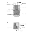
図1は、本発明の第1の実施形態におけるインクタンク10を示す概略斜視図である。図2(a)は、本発明の第1の実施形態におけるインクタンク10の概略断面図であり、図2(b)は、図2(a)において円で囲まれた領域付近の拡大断面図であり、第1のタンク部材1および第2のタンク部材2の接合部分を示している。 FIG. 1 is a schematic perspective view showing an ink tank 10 according to the first embodiment of the present invention. FIG. 2A is a schematic cross-sectional view of the ink tank 10 according to the first embodiment of the present invention, and FIG. 2B is an enlarged cross-sectional view in the vicinity of a region surrounded by a circle in FIG. It shows a joint portion between the first tank member 1 and the second tank member 2.
第1の実施形態におけるインクタンク10は、上部が開口した箱状に形成された第1のタンク部材1と、上部および下部が開口した箱状に形成された第2のタンク部材2と、蓋部材3とを有している。本実施形態では、第1のタンク部材1および第2のタンク部材2は、共にほぼ直方体状で、開口面における外寸が互いにほぼ等しくなるように形成されている。また、蓋部材3は、第2のタンク部材2の上部開口を閉塞できるような形状に形成されており、ここでは概ね板状となっている。 The ink tank 10 according to the first embodiment includes a first tank member 1 formed in a box shape with an upper portion opened, a second tank member 2 formed in a box shape with an upper portion and a lower portion opened, and a lid. Member 3. In the present embodiment, the first tank member 1 and the second tank member 2 are both substantially rectangular parallelepiped, and are formed so that the outer dimensions of the opening surfaces are substantially equal to each other. The lid member 3 is formed in a shape that can close the upper opening of the second tank member 2, and is generally plate-shaped here.
第1のタンク部材1および第2のタンク部材2は、第1のタンク部材1の開口端面11と第2のタンク部材2の下部開口端面21とが溶着によって接合されて、インク収納部4を形成している。インク収納部4には、インクを保持するインク保持部材5が収納されている。蓋部材3は、第2のタンク部材2の上部開口端面22に溶着接合されて、インク収納部4を閉塞することになる。蓋部材3には、インク注入口(図示せず)が設けられており、後述するインクタンク10の製造方法によっては、インクタンク10にインクを注入するために用いられる。 In the first tank member 1 and the second tank member 2, the opening end surface 11 of the first tank member 1 and the lower opening end surface 21 of the second tank member 2 are joined by welding, and the ink storage portion 4 is connected. Forming. The ink storage unit 4 stores an ink holding member 5 that holds ink. The lid member 3 is welded and joined to the upper opening end face 22 of the second tank member 2 to close the ink storage portion 4. The lid member 3 is provided with an ink injection port (not shown), and is used to inject ink into the ink tank 10 depending on a method of manufacturing the ink tank 10 described later.
箱状の第1のタンク部材1の底部には、インク排出口(図示せず)が設けられている。本実施形態のインクタンク10は、インクジェット記録ヘッドに装着可能に構成されているか、あるいはインクジェット記録ヘッドと一体に構成されていてよい。したがって、インクタンク10がインクジェット記録ヘッドに装着されている場合、インク排出口は、インク収納部4内のインクをインクジェット記録ヘッドへ供給するインク供給口となる。一方で、インクタンク10がインクジェット記録ヘッドと一体に形成されている場合、インク排出口は、記録ヘッドを通じて記録媒体にインク適を吐出するインク吐出口となる。 An ink discharge port (not shown) is provided at the bottom of the box-shaped first tank member 1. The ink tank 10 of the present embodiment may be configured to be attachable to the ink jet recording head, or may be configured integrally with the ink jet recording head. Therefore, when the ink tank 10 is mounted on the ink jet recording head, the ink discharge port becomes an ink supply port for supplying ink in the ink storage unit 4 to the ink jet recording head. On the other hand, when the ink tank 10 is formed integrally with the ink jet recording head, the ink discharge port becomes an ink discharge port that discharges ink to the recording medium through the recording head.
図2(b)に示すように、第2のタンク部材2において、第1のタンク部材1との溶着接合面となる下部開口端面21には、全周にわたって、溶着リブ23が設けられている。また、溶着リブ23は、第1のタンク部材1の開口端面11の出来るだけタンク内方側と対向するような位置に形成されている。
As shown in FIG. 2B, in the second tank member 2, a
第1のタンク部材1と第2のタンク部材2との接合は、この溶着リブ23が設けられた第2のタンク部材2を、固定されている第1のタンク部材1に対して所定の押圧力をかけながら微小な横振動を加えることで行われる。この微小振動により、溶着リブ23は、対向する第1のタンク部材1の開口端面11に対する摩擦熱で溶融されて、開口端面11に接合することになる。
The first tank member 1 and the second tank member 2 are joined together by pressing the second tank member 2 provided with the
このとき、この接合部分には、全周にわたって最大1ミリ程度のバリが発生し、インクタンク10の内方および外方側へ向かって共に突出することになる。溶着リブ23をタンク内方側へ配置したため、インクタンク10の内部、すなわちインク収納部5には、溶着接合面から最大で1ミリ程度のバリ6がはみ出すことになる。このタンク内部に発生するバリ6による不具合は、第2のタンク部材2の下部開口端面21の内周縁部が、第1のタンク部材1の開口端面11の内周縁部よりもタンク内方側に位置するように溶着を行うことで、回避可能である。本実施形態では、第2のタンク部材2の壁厚を第1のタンク部材1の壁厚よりも厚く形成して、2つのタンク部材1、2の外周が一致するように接合することで、上記の構成は達成されている。
At this time, a burr of about 1 mm at the maximum is generated at the joint portion over the entire circumference and protrudes both inward and outward of the ink tank 10. Since the
図3は、本実施形態における第2のタンク部材2の、下部開口端面21側から見た概略斜視図であり、陰影部分は第1のタンク部材1の開口端面11と接合される溶着接合面を表している。 FIG. 3 is a schematic perspective view of the second tank member 2 according to the present embodiment as viewed from the lower opening end face 21 side, and the shaded portion is a welded joining face joined to the opening end face 11 of the first tank member 1. Represents.
第2のタンク部材2の下部開口端面21において、内周縁部(図中太線参照)が、第1のタンク部材1の開口端面11の内周縁部(図中破線参照)よりもタンク内方に位置していることがわかる。これにより、図2(b)からもわかるように、第1のタンク部材1と第2のタンク部材2との接合部分には、段差が形成されることになる。この段差がインク収納部4に突出するバリ6の突出量と同程度の高さになるように、2つのタンク部材1、2の壁厚を適切に選択してやれば、バリ6はインク収納部5の上部開口側から見て、第2のタンク部材2の下に隠れることとなる。
In the lower opening end surface 21 of the second tank member 2, the inner peripheral edge (see the thick line in the figure) is more inward of the tank than the inner peripheral edge (see the broken line in the figure) of the opening end surface 11 of the first tank member 1. You can see that it is located. Thereby, as can be seen from FIG. 2B, a step is formed at the joint portion between the first tank member 1 and the second tank member 2. If the wall thicknesses of the two tank members 1 and 2 are appropriately selected so that the level difference is as high as the protruding amount of the
その結果、インク保持部材5がインク収納部4の上部開口から挿入される際に、バリ6とインク保持部材5とは接触しなくなる。このため、バリ6とインク保持部材5との接触によって生じる、バリ6がタンク内部へ落下することや、インク保持部材5がめくれて変形したりキズがついたりすることを防止することが可能となる。このようにして、溶着により発生したバリ6がインク収納部4にはみ出しても、インクタンク10としての機能が低下するといった不具合を回避することが可能となる。
As a result, when the ink holding member 5 is inserted from the upper opening of the ink storage portion 4, the
なお、タンク外方側に突出するバリは、タンク内方側に配置した溶着リブ23を完全に潰さずに溶融量を調節して溶着を行うことで、タンク外側にははみ出さないようにすることができる。それは、2つの開口端面11、21の間にタンク外方側に多少の隙間が形成され、溶着によって発生したバリがこの隙間を埋めるためである。これにより、本実施形態では、バリが外観を損ねるという問題は生じ得ない。
The burrs protruding outward from the tank are prevented from protruding outside the tank by adjusting the melt amount without completely crushing the
第1のタンク部材1と第2のタンク部材2との接合部分に形成される段差は、上記の不具合の回避のほか、インク保持部材5がインク収納部4内で浮き上がろうとするのを抑える役目も果たす。 The step formed at the joint between the first tank member 1 and the second tank member 2 prevents the ink holding member 5 from floating in the ink storage unit 4 in addition to avoiding the above-described problems. Also plays the role of suppressing.
インク保持部材5は、インク収納部4に収納された状態でその底面に密接している必要があるため、インク収納部4底面に押圧して収納されることになる。そのため、収納後に押圧状態を開放すると、インク保持部材5にはインク収納部4の底面から離れようとする力が働く。しかし、上述の段差があることで、インク収納部4から浮き上がろうとするインク保持部材5はこの段差と当接して、浮き上がりが抑えられることになる。したがって、この段差によって、インク保持部材5をインク収納部4から抜けにくくする効果も与えることができる。 Since the ink holding member 5 needs to be in close contact with the bottom surface of the ink storage unit 4 while being stored in the ink storage unit 4, the ink holding member 5 is pressed and stored on the bottom surface of the ink storage unit 4. For this reason, when the pressed state is released after storage, the ink holding member 5 is exerted with a force to move away from the bottom surface of the ink storage unit 4. However, due to the above-described step, the ink holding member 5 that is about to float from the ink storage portion 4 comes into contact with the step, and the lift is suppressed. Therefore, this step can also provide an effect of making it difficult for the ink holding member 5 to be removed from the ink storage portion 4.
次に、図4を参照しながら、本実施形態におけるインクタンク10の製造方法を説明する。 Next, a method for manufacturing the ink tank 10 in the present embodiment will be described with reference to FIG.
まず、図4(a)に示すように、第1のタンク部材1の開口端面11と第2のタンク部材2の下部開口端面21とを溶着接合して、インク収納部4を形成する。ここで、それぞれの開口端面11、21の外周縁部、つまり2つのタンク部材1、2の外周が互いにほぼ一致するように溶着を行う。 First, as shown in FIG. 4A, the opening end surface 11 of the first tank member 1 and the lower opening end surface 21 of the second tank member 2 are welded and joined to form the ink storage portion 4. Here, welding is performed so that the outer peripheral edge portions of the respective opening end faces 11 and 21, that is, the outer peripheries of the two tank members 1 and 2 substantially coincide with each other.
さらに、図4(b)に示すように、形成されたインク収納部4に、インク収納部4の上部開口からインク保持部材5を収納する。その後、インク収納部4へ所定のインクの注入を行う。このインク注入工程は、蓋部材3でインク収納部4を閉塞する前に、第2のタンク部材の上部開口から行うことができ、また、蓋部材3でインク収納部4を閉塞した後に、蓋部材3に設けられたインク注入口(図示せず)からでも行うことができる。蓋部材3によるインク収納部4の閉塞は、蓋部材3と第2のタンク部材2の上部開口端面22とを溶着接合することによって行う。このようにして、図4(c)に示すように、本実施形態のインクタンク10が製造される。 Further, as shown in FIG. 4B, the ink holding member 5 is stored in the formed ink storage portion 4 from the upper opening of the ink storage portion 4. Thereafter, predetermined ink is injected into the ink storage unit 4. This ink injection step can be performed from the upper opening of the second tank member before closing the ink storage portion 4 with the lid member 3, and after closing the ink storage portion 4 with the lid member 3, It can also be performed from an ink injection port (not shown) provided in the member 3. The ink container 4 is closed by the lid member 3 by welding and joining the lid member 3 and the upper opening end surface 22 of the second tank member 2. In this way, the ink tank 10 of the present embodiment is manufactured as shown in FIG.
また、内部にインク保持部材を収納した本実施形態の第1のタンク部材1で構成され、インクジェット記録ヘッドにインクを供給するために使用されていたインクタンクを再利用することでも、本実施形態のインクタンク10を製造することが可能である。 Further, the present embodiment can also be realized by reusing an ink tank that is configured by the first tank member 1 of the present embodiment, in which an ink holding member is housed, and used to supply ink to the ink jet recording head. Ink tank 10 can be manufactured.
この場合、第1のタンク部材1に収納されていたインク保持部材を取り出し、第1のタンク部材1と第2のタンク部材2とを溶着接合した後、第1のタンク部材1から取り出したインク保持部材とは別のインク保持部材を収納することができる。あるいは、第1のタンク部材1に収納されていたインク保持部材を取り出さずに、第1のタンク部材1と第2のタンク部材2とを溶着接合した後で、さらに別のインク保持部材を追加収納してもよい。 In this case, the ink holding member stored in the first tank member 1 is taken out, the first tank member 1 and the second tank member 2 are welded and joined, and then the ink taken out from the first tank member 1 is used. An ink holding member different from the holding member can be accommodated. Alternatively, after the first tank member 1 and the second tank member 2 are welded and joined without taking out the ink holding member stored in the first tank member 1, another ink holding member is added. It may be stored.
このように、例えば、2つ以上のインク保持部材がインク収納部4に収納される場合では、インク収納部4の底面と収納される最下部のインク保持部材との圧接、および収納されるインク保持部材同士の圧接が重要となる。この場合でも、第1のタンク部材1と第2のタンク部材2との接合部分に形成された段差が有効に作用する。 Thus, for example, when two or more ink holding members are stored in the ink storage unit 4, the pressure contact between the bottom surface of the ink storage unit 4 and the lowermost ink holding member stored, and the stored ink The pressure contact between the holding members is important. Even in this case, the step formed at the joint portion between the first tank member 1 and the second tank member 2 acts effectively.
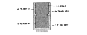
図5に示すように、収納される最上部のインク保持部材52が段差に当接するような構成にすることで、収納されるすべてのインク保持部材51、52の浮き上がりを抑制可能となる。これにより、インク収納部4の底面と最下部のインク保持部材51との圧接状態、および収納されるインク保持部材51、52同士の圧接状態を保持することが可能となる。 As shown in FIG. 5, when the stored uppermost ink holding member 52 is in contact with the step, the floating of all the stored ink holding members 51 and 52 can be suppressed. Thereby, it is possible to hold the pressure contact state between the bottom surface of the ink storage portion 4 and the lowermost ink holding member 51 and the pressure contact state between the ink holding members 51 and 52 to be stored.
本実施形態におけるインクタンクの製造方法は、バリの発生を抑える形状を溶着接合される2つの部材両方に形成する必要はなく、一方は既存の部材をそのまま利用することができ、それに合わせて、新たに1つの部材を準備するだけでよい。そのため、新規部材製作のコストを抑えることが可能となる他、上述のように、使用済みの既存製品をリサイクルして、新たな製品を製作できる点でも有利となる。 In the ink tank manufacturing method according to the present embodiment, it is not necessary to form a shape for suppressing the generation of burrs on both of the two members to be welded and joined, and one of them can use an existing member as it is. It is only necessary to prepare one new member. Therefore, it is possible to reduce the cost of manufacturing a new member, and as described above, it is advantageous in that a new product can be manufactured by recycling existing used products.
[第2の実施形態]
インク収納部4内部に突出するバリによる不具合を回避する上述の段差を形成するためには、開口方向すべてにわたって、第2のタンク部材2の壁厚を第1のタンク部材1の壁厚よりも厚くする必要はない。少なくとも、溶着接合面近傍、例えば下部開口端面21から数ミリ程度の範囲においてのみ、第2のタンク部材2の壁厚が第1のタンク部材1の壁厚よりも厚くなるように形成されていればよい。
[Second Embodiment]
In order to form the above-described step that avoids problems caused by burrs protruding into the ink storage portion 4, the wall thickness of the second tank member 2 is made to be greater than the wall thickness of the first tank member 1 over the entire opening direction. There is no need to make it thicker. The wall thickness of the second tank member 2 is formed to be thicker than the wall thickness of the first tank member 1 only at least in the vicinity of the welding joint surface, for example, within a range of several millimeters from the lower opening end surface 21. That's fine.
図6は、本発明の第2の実施形態におけるインクタンク10の概略断面図である。 FIG. 6 is a schematic cross-sectional view of the ink tank 10 according to the second embodiment of the present invention.
本実施形態では、第2のタンク部材2aの下部開口端に、タンク内方に突出したフランジ状の突出部7aが設けられている。これにより、溶着接合面に発生するバリをインク収納部4の開口部から見て突出部7aの下に隠すことができ、バリとインク保持部材5との接触を防ぐことができる。さらに、この突出部7aは、ある意味くさびの役割を果たすこととなり、インク収納部4からインク保持部材5をより抜けにくくする効果もある。 In the present embodiment, the lower opening end of the second tank member 2a, a flange-shaped projecting portion 7a that protrudes into the tank inwardly is provided. Thereby, the burr | flash which generate | occur | produces in the welding joining surface can be hidden under the protrusion part 7a seeing from the opening part of the ink storage part 4, and a contact with a burr | flash and the ink holding member 5 can be prevented. Further, the protruding portion 7a serves as a wedge in a sense, and has an effect of making it difficult for the ink holding member 5 to be removed from the ink storage portion 4.
また、図7に示すように、フランジ状の突出部7b、7cの上部開口側が、下部開口方向にかけて徐々に突出する曲面状に形成されているか、またはテーパー状に形成されていてよい。また、図8に示すように、フランジ状の突出部7dの先端を曲面状に形成したり、突出部7eの断面を三角形状に形成したりすることも可能である。 Moreover, as shown in FIG. 7, the upper opening side of the flange-shaped protrusions 7b and 7c may be formed in a curved shape that gradually protrudes in the lower opening direction, or may be formed in a tapered shape. Further, as shown in FIG. 8, it is also possible to form the tip of the flange-shaped projecting portion 7d in a curved shape, or to form the cross section of the projecting portion 7e in a triangular shape.
フランジ状の突出部7a−7eの断面形状をこのような形状にすることで、インク保持部材5の挿入性を損なうことなくバリによる不具合を回避して、さらに、インク保持部材5のインク収納部4からの浮き上がりをより抑えることが可能となる。特に、図9に示すように、インク収納部4にインク保持部材51、52を2つ以上収納する場合は、特に有効である。 By making the cross-sectional shape of the flange-like protrusions 7a-7e into such a shape, problems due to burrs can be avoided without impairing the insertability of the ink holding member 5, and the ink storage portion of the ink holding member 5 can be avoided. It is possible to further suppress the lifting from 4. In particular, as shown in FIG. 9, it is particularly effective when two or more ink holding members 51 and 52 are stored in the ink storage portion 4.
なお、上記構成以外のインクタンク10の構成や製造方法については、第1の実施形態と同様である。 The configuration and manufacturing method of the ink tank 10 other than the above configuration are the same as those in the first embodiment.
[第3の実施形態]
上記の実施形態において、第1のタンク部材1と第2のタンク部材2との接合部分における段差は、図3において太線と破線に囲まれた領域であるように、インク収納部4の内周すべてに形成されている。しかし、本発明では、全周にわたって段差が形成されている以外にも、部分的に形成されていてもよく、その場合も上述のバリによる不具合を回避する効果がある。部分的に段差を形成する場合には、インク収納部4の内周各辺に、少なくとも1つ以上の段差を形成する必要がある。その際、段差が形成されない箇所にインク保持部材5が入り込まないように、それぞれの段差の長さや、各段差間の間隔を適切に設定する必要がある。
[Third Embodiment]
In the above embodiment, the step at the joining portion between the first tank member 1 and the second tank member 2 is the area surrounded by the thick line and the broken line in FIG. It is formed in everything. However, in the present invention, a step may be formed in addition to the step being formed over the entire circumference, and in that case, there is an effect of avoiding the above-described problem caused by the burr. When a step is partially formed, it is necessary to form at least one step on each inner peripheral side of the ink storage unit 4. At that time, it is necessary to appropriately set the length of each step and the interval between the steps so that the ink holding member 5 does not enter the portion where the steps are not formed.
なお、このような段差を形成するための第2のタンク部材2の構成は、第1および第2の実施形態と同様であり、インクタンク10の製造方法は、第1の実施形態と同様である。 The configuration of the second tank member 2 for forming such a step is the same as in the first and second embodiments, and the method for manufacturing the ink tank 10 is the same as in the first embodiment. is there.
1 第1のタンク部材
11 開口端面
2、2a−2e 第2のタンク部材
21 下部開口端面
22 上部開口端面
3 蓋部材
4 インク収納部
5、51、52 インク保持部材
7a−7e 突出部
10 インクタンク
DESCRIPTION OF SYMBOLS 1 1st tank member 11 Opening end surface 2, 2a-2e 2nd tank member 21 Lower opening end surface 22 Upper opening end surface 3 Lid member 4 Ink storage part 5, 51, 52 Ink holding member 7a-7e Protrusion part 10 Ink tank
Claims (16)
前記第2のタンク部材の前記下部開口端面の内周縁部の少なくとも一部が、前記第1のタンク部材の前記開口端面の内周縁部よりタンク内方に位置していることを特徴とするインクタンク。 It has a first tank member which top is open, and a second tank member upper and lower are open, and the lid member, and the ink holding member for holding the ink supplied to the ink jet recording head, the said An opening end surface forming the opening of the first tank member and a lower opening end surface forming the lower opening of the second tank member are welded and joined to form an ink storage portion, and the ink holding member is used as the ink storage portion. In the ink tank in which the lid member and the upper opening end surface forming the upper opening of the second tank member are welded and joined to close the ink storage portion,
At least a part of the inner peripheral edge of the lower opening end face of the second tank member is located inside the tank from the inner peripheral edge of the opening end face of the first tank member. tank.
前記突出部は、前記下部開口端面の前記内周縁部を有することを特徴とする、請求項1に記載のインクタンク。 The second tank member has a protruding portion protruding inward of the tank ,
The protrusion is characterized Rukoto to have a the inner periphery of the lower opening end face, the ink tank according to claim 1.
前記第2のタンク部材の下部開口を形成する下部開口端面の内周縁部の少なくとも一部が、前記第1のタンク部材の開口を形成する開口端面の内周縁部よりタンク内方に位置するように、前記第1のタンク部材の前記開口端面と、前記第2のタンク部材の前記下部開口端面と、を溶着接合してインク収納部を形成する工程と、
前記インク収納部に前記インク保持部材を収納する工程と、
前記インク保持部材が収納された前記インク収納部に前記インクを注入する工程と、
を有することを特徴とするインクタンクの製造方法。 Preparing a first tank member having an upper opening, a second tank member having upper and lower openings, ink, and an ink holding member for holding the ink;
At least a part of the inner peripheral edge portion of the lower opening end surface forming the lower opening of the second tank member is located inside the tank from the inner peripheral edge portion of the opening end surface forming the opening of the first tank member. in a step of forming said opening end face of said first tank member, said the and lower opening end face, and fusion bonded to the ink containing portion of the second tank member,
A step of accommodating the ink holding member to said ink containing portion,
A step of injecting the ink into the ink storage portion in which the ink holding member is housed,
A method for manufacturing an ink tank, comprising:
前記第2開口形成面の内周縁部の少なくとも一部が、前記第1開口形成面の内周縁部よりタンク内方に位置していることを特徴とするインクタンク。An ink tank, wherein at least a part of an inner peripheral edge portion of the second opening forming surface is located inward of the tank from an inner peripheral edge portion of the first opening forming surface.
前記第2開口形成面の内周縁部の少なくとも一部が、前記第1開口形成面の内周縁部よりタンク内方に位置するように、前記第2開口形成面と前記第1開口形成面とを溶着接合してインク収納部を形成する工程と、The second opening forming surface and the first opening forming surface such that at least a part of the inner peripheral edge portion of the second opening forming surface is located inside the tank from the inner peripheral edge portion of the first opening forming surface; Forming an ink storage portion by welding and bonding,
前記インク保持部材を前記第3の開口から前記インク収納部内に挿入する工程と、Inserting the ink holding member into the ink container from the third opening;
前記蓋部材と前記第3開口形成面とを溶着接合して、前記インク保持部材が挿入された前記インク収納部を閉塞する工程と、Welding the lid member and the third opening forming surface and closing the ink storage portion into which the ink holding member is inserted;
を有することを特徴とするインクタンクの製造方法。A method for manufacturing an ink tank, comprising:
Priority Applications (1)
| Application Number | Priority Date | Filing Date | Title |
|---|---|---|---|
| JP2008160310A JP5111252B2 (en) | 2008-06-19 | 2008-06-19 | Ink tank and manufacturing method thereof |
Applications Claiming Priority (1)
| Application Number | Priority Date | Filing Date | Title |
|---|---|---|---|
| JP2008160310A JP5111252B2 (en) | 2008-06-19 | 2008-06-19 | Ink tank and manufacturing method thereof |
Publications (2)
| Publication Number | Publication Date |
|---|---|
| JP2010000648A JP2010000648A (en) | 2010-01-07 |
| JP5111252B2 true JP5111252B2 (en) | 2013-01-09 |
Family
ID=41582768
Family Applications (1)
| Application Number | Title | Priority Date | Filing Date |
|---|---|---|---|
| JP2008160310A Expired - Fee Related JP5111252B2 (en) | 2008-06-19 | 2008-06-19 | Ink tank and manufacturing method thereof |
Country Status (1)
| Country | Link |
|---|---|
| JP (1) | JP5111252B2 (en) |
Family Cites Families (2)
| Publication number | Priority date | Publication date | Assignee | Title |
|---|---|---|---|---|
| JP3308751B2 (en) * | 1995-02-21 | 2002-07-29 | キヤノン株式会社 | Ink tank and manufacturing method thereof |
| JP3658373B2 (en) * | 2002-02-22 | 2005-06-08 | キヤノン株式会社 | Liquid storage container, ink jet cartridge, and ink jet recording apparatus |
-
2008
- 2008-06-19 JP JP2008160310A patent/JP5111252B2/en not_active Expired - Fee Related
Also Published As
| Publication number | Publication date |
|---|---|
| JP2010000648A (en) | 2010-01-07 |
Similar Documents
| Publication | Publication Date | Title |
|---|---|---|
| JP5950595B2 (en) | TANK AND METHOD FOR MANUFACTURING TANK | |
| US10581058B2 (en) | Welding assembly for liquid-injection hole of secondary battery | |
| JP4875226B2 (en) | Battery storage case and battery pack provided with the same | |
| JP5435962B2 (en) | Liquid jet recording head and method for manufacturing liquid jet recording head | |
| JP5045752B2 (en) | Sealed battery, method for manufacturing the same, vehicle equipped with the battery, and battery-equipped device | |
| KR101695416B1 (en) | Laser welding structure | |
| JP2007326374A (en) | Method for manufacturing ink cartridge | |
| JP2012192749A (en) | Liquid ejection head, and method for manufacturing the liquid ejection head | |
| JP5111252B2 (en) | Ink tank and manufacturing method thereof | |
| JP2008001004A (en) | Manufacturing method of liquid feeding part of liquid storage container and liquid storage container | |
| JP4294341B2 (en) | Sealed battery and its manufacturing method | |
| JP5219533B2 (en) | Ink cartridge and method of manufacturing ink cartridge | |
| KR101019724B1 (en) | Ink tank and ink catridge | |
| JP2009132077A (en) | Inkjet cartridge and manufacturing method therefor | |
| JP4930763B2 (en) | Filling lid for bottom-filling type feeding containers | |
| JP3631747B1 (en) | Ink cartridge and ink package used therefor | |
| JP2006240245A (en) | Method for adhering filter and liquid discharge head cartridge | |
| JP2002120383A (en) | Vessel | |
| JP3129668B2 (en) | Welding part structure of outer case of electric double layer capacitor | |
| CN118617863A (en) | Ink cartridge and method for remanufacturing ink cartridge | |
| JP2024115532A (en) | Container, container manufacturing method, and container remanufacturing method | |
| JP5023168B2 (en) | ink cartridge | |
| CN111746902B (en) | Liquid storage bottle and method for manufacturing the same, and resin member and method for manufacturing the same | |
| JP2013158977A (en) | Ink tank | |
| CN111746905B (en) | Liquid storage bottle and manufacturing method thereof |
Legal Events
| Date | Code | Title | Description |
|---|---|---|---|
| A621 | Written request for application examination |
Free format text: JAPANESE INTERMEDIATE CODE: A621 Effective date: 20110128 |
|
| A977 | Report on retrieval |
Free format text: JAPANESE INTERMEDIATE CODE: A971007 Effective date: 20120622 |
|
| A131 | Notification of reasons for refusal |
Free format text: JAPANESE INTERMEDIATE CODE: A131 Effective date: 20120626 |
|
| A521 | Request for written amendment filed |
Free format text: JAPANESE INTERMEDIATE CODE: A523 Effective date: 20120822 |
|
| TRDD | Decision of grant or rejection written | ||
| A01 | Written decision to grant a patent or to grant a registration (utility model) |
Free format text: JAPANESE INTERMEDIATE CODE: A01 Effective date: 20120911 |
|
| A01 | Written decision to grant a patent or to grant a registration (utility model) |
Free format text: JAPANESE INTERMEDIATE CODE: A01 |
|
| A61 | First payment of annual fees (during grant procedure) |
Free format text: JAPANESE INTERMEDIATE CODE: A61 Effective date: 20121009 |
|
| FPAY | Renewal fee payment (event date is renewal date of database) |
Free format text: PAYMENT UNTIL: 20151019 Year of fee payment: 3 |
|
| R151 | Written notification of patent or utility model registration |
Ref document number: 5111252 Country of ref document: JP Free format text: JAPANESE INTERMEDIATE CODE: R151 |
|
| FPAY | Renewal fee payment (event date is renewal date of database) |
Free format text: PAYMENT UNTIL: 20151019 Year of fee payment: 3 |
|
| LAPS | Cancellation because of no payment of annual fees |