JP5110141B2 - Satellite radio wave receiving apparatus and satellite radio wave receiving method - Google Patents
Satellite radio wave receiving apparatus and satellite radio wave receiving method Download PDFInfo
- Publication number
- JP5110141B2 JP5110141B2 JP2010219006A JP2010219006A JP5110141B2 JP 5110141 B2 JP5110141 B2 JP 5110141B2 JP 2010219006 A JP2010219006 A JP 2010219006A JP 2010219006 A JP2010219006 A JP 2010219006A JP 5110141 B2 JP5110141 B2 JP 5110141B2
- Authority
- JP
- Japan
- Prior art keywords
- satellite
- radio wave
- signal
- frequency
- reception
- Prior art date
- Legal status (The legal status is an assumption and is not a legal conclusion. Google has not performed a legal analysis and makes no representation as to the accuracy of the status listed.)
- Active
Links
Images


Classifications
-
- G—PHYSICS
- G01—MEASURING; TESTING
- G01S—RADIO DIRECTION-FINDING; RADIO NAVIGATION; DETERMINING DISTANCE OR VELOCITY BY USE OF RADIO WAVES; LOCATING OR PRESENCE-DETECTING BY USE OF THE REFLECTION OR RERADIATION OF RADIO WAVES; ANALOGOUS ARRANGEMENTS USING OTHER WAVES
- G01S19/00—Satellite radio beacon positioning systems; Determining position, velocity or attitude using signals transmitted by such systems
- G01S19/01—Satellite radio beacon positioning systems transmitting time-stamped messages, e.g. GPS [Global Positioning System], GLONASS [Global Orbiting Navigation Satellite System] or GALILEO
- G01S19/13—Receivers
- G01S19/24—Acquisition or tracking or demodulation of signals transmitted by the system
- G01S19/29—Acquisition or tracking or demodulation of signals transmitted by the system carrier including Doppler, related
-
- G—PHYSICS
- G01—MEASURING; TESTING
- G01S—RADIO DIRECTION-FINDING; RADIO NAVIGATION; DETERMINING DISTANCE OR VELOCITY BY USE OF RADIO WAVES; LOCATING OR PRESENCE-DETECTING BY USE OF THE REFLECTION OR RERADIATION OF RADIO WAVES; ANALOGOUS ARRANGEMENTS USING OTHER WAVES
- G01S19/00—Satellite radio beacon positioning systems; Determining position, velocity or attitude using signals transmitted by such systems
- G01S19/01—Satellite radio beacon positioning systems transmitting time-stamped messages, e.g. GPS [Global Positioning System], GLONASS [Global Orbiting Navigation Satellite System] or GALILEO
- G01S19/13—Receivers
- G01S19/35—Constructional details or hardware or software details of the signal processing chain
- G01S19/37—Hardware or software details of the signal processing chain
Landscapes
- Engineering & Computer Science (AREA)
- Radar, Positioning & Navigation (AREA)
- Remote Sensing (AREA)
- Computer Networks & Wireless Communication (AREA)
- Physics & Mathematics (AREA)
- General Physics & Mathematics (AREA)
- Signal Processing (AREA)
- Position Fixing By Use Of Radio Waves (AREA)
Description
この発明は、測位用衛星から電波を受信して衛星信号を取得する衛星電波受信装置および衛星電波受信方法に関する。 The present invention relates to a satellite radio wave receiving apparatus and a satellite radio wave receiving method for receiving a radio wave from a positioning satellite and acquiring a satellite signal.
従来、GPS(Global Positioning System)をはじめとするGNSS(Global Navigation Satellite System)に係る測位用衛星から電波を受信し、時刻情報や位置情報を取得する時計やGPSロガーといった携帯型装置がある。これらの携帯型装置では、電源の制約から低消費電力の部品を利用したり、省電力動作を行ったりしている。 2. Description of the Related Art Conventionally, there are portable devices such as a clock and a GPS logger that receive radio waves from positioning satellites related to GNSS (Global Navigation Satellite System) such as GPS (Global Positioning System) and acquire time information and position information. These portable devices use low power consumption components or perform power saving operations due to power supply restrictions.
例えば、特許文献1には、測位用衛星から時刻情報を取得する際に、衛星信号のうち時刻情報が送信されるタイミング以外の期間では受信動作を中断させる技術が開示されている。また、特許文献2には、高度センサを備え、飛行機による移動が行われたと判断された場合にのみ4衛星からのデータ受信を行って位置情報を取得し、タイムゾーンを判別する時刻修正装置が開示されている。
For example,
ところで、測位用衛星から送信される電波の送信周波数は、複数の測位用衛星において同一である。例えば、GPSにおける測位用衛星(GPS衛星)から送信される民間用電波周波数の1つは、L1帯の1.57542GHzである。しかしながら、各GPS衛星が軌道上を高速で移動することで携帯型装置との間の相対運動によりドップラー効果が働き、この携帯型装置での受信周波数は、それぞれ送信周波数から外れた周波数となる。従って、予め自機の現在位置データや測位用衛星の軌道情報を有しない携帯型装置で測位用衛星からの電波を受信する際には、ドップラー効果により変化し得る範囲で測位用衛星からの電波の受信周波数を探索しなければならない。 By the way, the transmission frequency of the radio wave transmitted from the positioning satellite is the same among the plurality of positioning satellites. For example, one of commercial radio frequencies transmitted from a positioning satellite (GPS satellite) in GPS is 1.57542 GHz in the L1 band. However, as each GPS satellite moves at high speed in orbit, the Doppler effect works due to the relative movement with the portable device, and the reception frequency at this portable device is a frequency deviating from the transmission frequency. Therefore, when receiving a radio wave from a positioning satellite with a portable device that does not have its own current position data or positioning satellite orbit information in advance, the radio wave from the positioning satellite is within a range that can be changed by the Doppler effect. The received frequency must be searched.
一方、携帯型装置内で受信電波から衛星信号を復調したり、デジタルサンプリングしたりするための周波数信号を生成する発振回路は、その発振周波数にそれぞれ誤差が存在する。そして、携帯型装置に搭載可能な小型、且つ、低消費電力の発振回路では、この発振周波数の誤差が大きくなるという問題がある。従って、測位用衛星からの電波を検出する際には、発振周波数の誤差の範囲も含めて広い受信周波数の範囲を探索しなければならず、結局探索時間が長くなって消費電力量が増大するという課題があった。 On the other hand, an oscillation circuit that generates a frequency signal for demodulating a satellite signal from a received radio wave or performing digital sampling in a portable device has an error in its oscillation frequency. A small-sized and low-power oscillation circuit that can be mounted on a portable device has a problem that the oscillation frequency error becomes large. Therefore, when detecting a radio wave from a positioning satellite, it is necessary to search a wide reception frequency range including an error range of the oscillation frequency, which eventually increases the search time and power consumption. There was a problem.
この発明の目的は、消費電力を増加させずに衛星電波の検出時間を短縮することが可能な衛星電波受信装置および衛星電波受信方法を提供することにある。 An object of the present invention is to provide a satellite radio wave receiving apparatus and a satellite radio wave receiving method capable of shortening a satellite radio wave detection time without increasing power consumption.
上記目的を達成するため、請求項1記載の発明は、
測位用衛星から送信された衛星信号を取得する衛星電波受信装置において、
前記測位用衛星が送信する周波数を含む予め設定された周波数範囲の電波を受信可能な受信手段と、
前記受信手段により受信された電波に基づく受信信号から前記衛星信号を検出する捕捉手段と、
前記捕捉手段により検出された複数の前記衛星信号の受信周波数に基づいて、当該検出された複数の前記衛星信号の中心周波数を算出する算出手段と、
を備え、
前記捕捉手段は、前記中心周波数を基準として前記衛星信号の検出を行う
ことを特徴としている。
In order to achieve the above object, the invention according to
In the satellite radio wave receiver that acquires the satellite signal transmitted from the positioning satellite,
Receiving means capable of receiving radio waves in a preset frequency range including the frequency transmitted by the positioning satellite;
Capturing means for detecting the satellite signal from a received signal based on the radio wave received by the receiving means;
Calculation means for calculating center frequencies of the detected plurality of satellite signals based on reception frequencies of the plurality of satellite signals detected by the acquisition means;
With
The capturing means detects the satellite signal with the center frequency as a reference.
請求項2記載の発明は、請求項1記載の衛星電波受信装置において、
前記捕捉手段により検出された前記衛星信号の受信周波数と、当該受信周波数における前記衛星信号の信号強度を示す強度指標とを関連付けて記憶する記憶手段を備え、
前記算出手段は、前記記憶手段に記憶された複数の前記衛星信号に係る前記受信周波数の前記強度指標による重み付平均により前記中心周波数を算出する
ことを特徴としている。
The invention according to
Storage means for associating and storing the reception frequency of the satellite signal detected by the acquisition means and an intensity index indicating the signal intensity of the satellite signal at the reception frequency;
The calculation means is characterized in that the center frequency is calculated by a weighted average based on the intensity index of the reception frequencies related to the plurality of satellite signals stored in the storage means.
請求項3記載の発明は、請求項1又は2記載の衛星電波受信装置において、
前記捕捉手段は、前記中心周波数と、前記衛星信号の検出を行う受信周波数とのズレの大きさがゼロから増加していくように受信周波数を変化させながら前記衛星信号の検出を行う
ことを特徴としている。
The invention described in
The capturing means detects the satellite signal while changing the reception frequency so that the deviation between the center frequency and the reception frequency for detecting the satellite signal increases from zero. It is said.
請求項4記載の発明は、請求項1〜3の何れか一項に記載の衛星電波受信装置において、
前記捕捉手段は、前記中心周波数を中心にして予め定められた周波数範囲に亘って前記衛星信号の検出を行う
ことを特徴としている。
The invention according to
The acquisition means is characterized in that the satellite signal is detected over a predetermined frequency range centering on the center frequency.
請求項5記載の発明は、請求項2記載の衛星電波受信装置において、
前記記憶手段は、予め定められた数の前記受信周波数及び前記強度指標を記憶可能であり、前記捕捉手段により検出された前記衛星信号のうち、最新の前記予め定められた数の前記受信周波数及び前記強度指標を記憶する
ことを特徴としている。
The invention according to
The storage means can store a predetermined number of the reception frequencies and the intensity index, and among the satellite signals detected by the acquisition means, the latest predetermined number of the reception frequencies and The intensity index is stored.
請求項6記載の発明は、請求項2記載の衛星電波受信装置において、
前記強度指標は、前記衛星信号が検出された前記受信周波数における当該衛星信号が検出されたときの信号強度と、前記受信周波数で当該衛星信号が検出されなかったときの平均信号強度との比である
ことを特徴としている。
The invention according to
The intensity index is a ratio of a signal intensity when the satellite signal is detected at the reception frequency where the satellite signal is detected and an average signal intensity when the satellite signal is not detected at the reception frequency. It is characterized by being.
請求項7記載の発明は、
測位用衛星から送信された電波を受信する受信手段を備え、当該受信手段により受信された電波から衛星信号を取得する衛星電波受信方法において、
前記受信手段により受信された電波に基づく受信信号から前記衛星信号を検出する捕捉ステップと、
前記捕捉ステップで検出された複数の前記衛星信号の受信周波数に基づいて、当該検出された複数の前記衛星信号の中心周波数を算出する算出ステップと、
を含み、
前記捕捉ステップは、前記中心周波数を基準として前記衛星信号の検出を行う
ことを特徴としている。
The invention described in
In a satellite radio wave receiving method comprising a receiving means for receiving a radio wave transmitted from a positioning satellite, and acquiring a satellite signal from the radio wave received by the receiving means,
A capturing step of detecting the satellite signal from a received signal based on the radio wave received by the receiving means;
A calculation step of calculating center frequencies of the detected plurality of satellite signals based on reception frequencies of the plurality of satellite signals detected in the acquisition step;
Including
The acquisition step is characterized in that the satellite signal is detected with reference to the center frequency.
本発明に従うと、測位用衛星から送信された衛星信号を取得する衛星電波受信装置および衛星電波受信方法において、受信した電波から検出された複数の衛星信号の受信周波数に基づいて中心周波数を算出し、次回の衛星信号の検出時には、この算出された中心周波数を基準に設定された周波数範囲で検出が行われるので、受信動作時間を短縮し、消費電力を抑えることができるという効果がある。 According to the present invention, in a satellite radio wave receiver and satellite radio wave reception method for acquiring a satellite signal transmitted from a positioning satellite, a center frequency is calculated based on reception frequencies of a plurality of satellite signals detected from received radio waves. In the next detection of the satellite signal, detection is performed in the frequency range set based on the calculated center frequency, so that the reception operation time can be shortened and the power consumption can be suppressed.
以下、本発明の実施の形態の衛星電波受信装置を図面に基づいて説明する。 Hereinafter, a satellite radio wave receiving apparatus according to an embodiment of the present invention will be described with reference to the drawings.
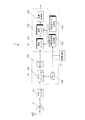
図1は、本実施形態の衛星電波受信装置の構成および信号の流れを示すブロック図である。 FIG. 1 is a block diagram showing the configuration and signal flow of the satellite radio wave receiver of the present embodiment.
この衛星電波受信装置1は、例えば、携帯型時計に搭載されて時刻情報を出力するものである。衛星電波受信装置1は、受信アンテナANTと、低雑音増幅器(LNA)11と、狭帯域フィルタ12と、発振回路13と、RF部14と、ベースバンド部15などを備えている。
The satellite
受信アンテナANTは、GPS衛星からのL1帯(1.57542GHz)の電波が受信可能なアンテナである。また、狭帯域フィルタ12は、例えば、SAWフィルタ(表面弾性波フィルタ)であり、1〜10MHz程度の帯域を有する。この帯域幅は、GPS衛星からの送信周波数と衛星電波受信装置1による受信周波数との間のドップラー効果による周波数のずれの大きさや、衛星信号を復調する際に入力される中間周波数帯のローカル周波数信号に含まれる周波数誤差の大きさに比べて十分に広い。これらの受信アンテナANT、低雑音増幅器11、狭帯域フィルタ12、および、RF部14により、受信手段が構成される。
The receiving antenna ANT is an antenna capable of receiving radio waves in the L1 band (1.57542 GHz) from GPS satellites. The
発振回路13は、例えば、温度補償回路を備えた水晶発振器(TCXO)が一般的に使われているが、本発明では温度補償を行わない低消費電力の水晶発振器でも利用可能である。この発振回路13は、基準周波数として、例えば、16.368MHzの信号を生成して出力する。この発振回路13は、精度の高い大型、および/または、高価なものではなく、安価で消費電力の小さい小型のものである。従って、この発振回路13の発振する基準周波数には、発振回路13に固有な±10〜15kHz程度のオフセット誤差が含まれている。
As the
RF部14は、受信した電波に基づく搬送波周波数の受信信号を中間周波数帯の信号に変換し、デジタルデータ化して出力する。このRF部14は、ダウンコンバータ141と、PLL(Phase Locked Loop)142と、ADC(アナログ・デジタル変換器)143などを備えている。
The
ダウンコンバータ141は、受信した電波に基づく搬送波周波数の受信信号を中間周波数の信号に変換する回路であり、例えば、ミキサや狭帯域フィルタを備えている。中間周波数fiは、例えば、4MHz程度の値である。
The down
PLL142は、発振回路13の出力信号に同期してダウンコンバータ141のミキサに所定のローカル周波数の信号を入力する回路であり、例えば、VCO(Voltage Controlled Oscillator)、プリスケーラ、および、位相比較器などを備えている。VCOは、入力される直流電圧によって定められる周波数の信号を生成してダウンコンバータ141のミキサに出力する。プリスケーラは、このVCOの出力信号を分周して、位相比較器に出力する。位相比較器は、VCOの分周信号の位相と、発振回路の出力信号の位相とを比較して、これらの位相差に基づく直流電圧をVCOへ出力する。このような構成によりローカル周波数を制御することで、一定の周波数信号を安定してダウンコンバータ141へ出力することが可能となる。
The
ADC143は、中間周波数帯の信号に変換されてダウンコンバータ141から出力された受信信号を所定のサンプリング周波数でデジタル値に変換してベースバンド部15へ出力する。
The
ベースバンド部15は、捕捉エンジン151(捕捉手段)と、追尾エンジン152と、中間周波数生成器153と、逆拡散コード生成器154と、演算処理部155などを備えている。また、ベースバンド部15には、ベースバンド部15の動作を統括し、CPU(Central Processing Unit)などを含むコントローラ156(算出手段)と、一時データを記憶するRAM(Random Access Memory)などのメモリ157(記憶手段)とが含まれている(図2参照)。
The
捕捉エンジン151は、RF部14から入力したデジタル信号から衛星信号を検出してその受信周波数と衛星識別番号とを同定する処理を行う回路であり、後に詳述する。
The
追尾エンジン152は、捕捉エンジン151で同定された受信周波数および衛星識別番号を有する衛星信号と、衛星電波受信装置1の内部クロックとの間で位相同期点を検出し、また、この位相同期を維持して復調した衛星信号を継続的に出力する回路である。
The
中間周波数生成器153は、RF部14から入力したデジタル信号から衛星信号を復調する際に捕捉エンジン151、又は、追尾エンジン152に入力する中間周波数ローカル信号を生成する。この中間周波数生成器153は、本実施形態のベースバンド部15では、NCO(Numerically-Controlled Oscillator、数値制御発振器)である。このNCOに入力される数値によって、生成する中間周波数ローカル信号の周波数を細かく変更することができる。また、中間周波数生成器153は、I相(In Phase)ローカル信号と、このI相ローカル信号と直交するQ相(Quadrature Phase)ローカル信号とをそれぞれ出力可能に構成されている。
The
逆拡散コード生成器154は、指定された衛星識別番号に対応するGPS衛星において衛星信号を拡散変調している拡散コードを生成し、捕捉エンジン151、又は、追尾エンジン152に出力する。本実施形態の衛星電波受信装置1における逆拡散コード生成器154では、拡散コードとしてC/Aコードが生成される。C/Aコードは、一周期1msの期間に送信される1023個の符号データ(チップ)の配列により構成されている。
The
演算処理部155は、追尾エンジン152から出力された衛星信号を復号して時刻データの取得を行う。また、演算処理部155は、必要に応じてGPS衛星の位置の算出、および、衛星電波受信装置1の現在位置の算出を行って、これらの取得データや算出データを所定のフォーマットで出力する。
The
次に、捕捉エンジン151における衛星信号の検出処理について説明する。
Next, satellite signal detection processing in the
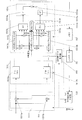
図2は、捕捉エンジン151およびこれに関連する部分の構成を示す図である。
FIG. 2 is a diagram showing the configuration of the
捕捉エンジン151は、I/Q変換部1511と、積分部1512と、相関器1513と、二乗回路1514などを備えている。
The
I/Q変換部1511は、入力信号をI相信号と、I相信号に直交するQ相信号とに分離して出力する。このI/Q変換部1511は、ミキサ1511a、1511bを備える。RF部14からI/Q変換部1511に入力して2系統に分離された中間周波数帯のデジタル信号は、それぞれに対し中間周波数生成器153から出力されたI相ローカル信号およびQ相ローカル信号がミキサ1511a、1511bで混合される。I相ローカル信号およびQ相ローカル信号の周波数が入力されたデジタル信号の中間周波数と同一であり、且つ、デジタル信号の位相と内部クロックの位相とが完全に同期した場合には、ミキサ1511a、1511bからの出力信号は、それぞれI相のローカル信号、および、Q相のローカル信号となる。
The I /
積分部1512は、ミキサ1511a、1511bの出力信号をそれぞれC/Aコード1チップの長さ、即ち、1/1023ms(〜1μs)に亘って積分して出力する積分器1512a、1512bを備えている。或いは、これらの積分器1512a、1512bは、C/Aコード1チップの長さに比して短い交流成分をカットするローパスフィルタであってもよい。
The
相関器1513は、積分器1512a、1512bの出力データをそれぞれ積分周期ごとに取得して、これらの取得された出力信号と生成されたC/Aコードとの間の相関を求めるマッチドフィルタである。積分器1512aの出力データは、シフトレジスタ1513aに入力され、また、積分器1512bの出力データは、シフトレジスタ1513bに入力される。シフトレジスタ1513a、1513bでは、それぞれ1023個のデータが入力された順に直列に蓄積されていく。
The
シフトレジスタ1513eには、シフトレジスタ1513a、1513bと同一個数、即ち、C/Aコード一周期分に当たる1023チップのデータが逆拡散コード生成器154から順に入力される。このシフトレジスタ1513eは、4衛星分のC/Aコードを同時並列的に記憶可能であり、セレクタ1513fにより何れかのGPS衛星のC/Aコードが1つ選択される。セレクタ1513fにより選択されたGPS衛星のC/Aコードを表す各チップデータは、シフトレジスタ1513a、1513bに記憶された同位相の(同一順番に入力された)各データと乗算されて加算器1513c、1513dにそれぞれ入力される。加算器1513c、1513dは、それぞれ1023個の乗算器から入力された値を加算して二乗回路1514へ出力する。
The same number of
二乗回路1514は、相関器1513から入力されたI相信号の加算値、および、Q相信号の加算値をそれぞれ二乗する二乗計算部1514a、1514bと、二乗計算部1514a、1514bの計算結果の和を算出する加算器1514cとを備える。加算器1514cの計算結果は、ベースバンド部15のメモリ157へ出力されて後述する所定の位置に記憶される。なお、加算器1514cの出力の平方根を出力することとしても良い。
The
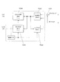
図3は、ベースバンド部15の中間周波数生成器153の構成を示すブロック図である。
FIG. 3 is a block diagram illustrating a configuration of the
この中間周波数生成器153は、NCOであり、加算器1531、1532と、レジスタ1533と、COS ROM1534と、SIN ROM1535などにより構成されている。
The
加算器1531には、設定されたIFタイミングの値およびオフセットの値が入力され、これらの値は、加算器1531で加算されて加算器1532に送られる。加算器1532では、この加算器1531から入力された値とレジスタ1533から入力された値とが加算され、COS ROM1534およびSIN ROM1535に送られるとともに、レジスタ1533に記憶される。即ち、レジスタ1533に記憶される値は、予め定められた時間間隔で加算器1531から加算器1532に入力された値ずつ増加していく。そして、レジスタ1533に記憶された値が最大値となって、更に0に戻ることで、一周期の経過が示されることになる。加算器1532およびレジスタ1533は、特に限られないが、例えば、32bitのデータ容量を有する。
The set IF timing value and offset value are input to the
COS ROM1534およびSIN ROM1535は、それぞれ、振幅が1の余弦関数および正弦関数の一周期を、例えば、8bitで表される256の位相に等分割し、各位相での余弦関数および正弦関数の値を位相に対応するアドレスから読み出して出力するルックアップテーブルを備えたROMである。加算器1532からCOS ROM1534およびSIN ROM1535に32bitの数値が入力されると、例えば、そのうちの上位8bitの値によって示される位相に対応するアドレスから余弦関数および正弦関数の値が読み出される。そして、これらの値が予め定められた時間間隔で次々に読み出されていくことで、指定された周波数のI相ローカル信号LoIおよびQ相ローカル信号LoQとなる。
Each of the
ここで、IFタイミングの設定入力値は、標準の中間周波数、即ち、本実施形態の衛星電波受信装置1では、中間周波数fi=4.092MHzに対応する値である。従って、中間周波数のオフセット値(受信チャンネルf)が0の場合には、中間周波数fi=4.092MHzのローカル周波数信号が出力される。一方、オフセット値を0から変化させることにより、出力するローカル周波数を4.092MHzからデジタル的に増減させることが可能となる。本実施形態の衛星電波受信装置1では、受信チャンネルfの変化1に対応する周波数変化量Δfを100Hzとする。従って、受信チャンネルfが1増加するごとに出力されるローカル周波数が中間周波数fiから100Hzずつ上昇し、受信チャンネルfが1減少するごとに出力されるローカル周波数が中間周波数fiから100Hzずつ下降する。
Here, the set input value of the IF timing is a standard intermediate frequency, that is, a value corresponding to the intermediate frequency fi = 4.092 MHz in the satellite
図4は、ベースバンド部15のメモリ157における記憶データの配列パターンを示した図である。
FIG. 4 is a diagram showing an arrangement pattern of stored data in the
メモリ157に記憶させるデータは、先ず、図4(a)に示すように、C/Aコードの位相、受信周波数(受信チャンネル)、および、衛星識別番号の3つの変数による三次元配列上に配置される。捕捉エンジン151においてこれらの3つの変数を設定して求められた相関値の出力データは、これらの3つの変数により定められる位置に記憶される。
As shown in FIG. 4A, data stored in the
また、図4(a)に示した三次元配列に記憶された値に基づき、後述する方法で算出されたS/N比の値sが設定された閾値aよりも大きい場合には、衛星信号が検出されたものと判断される。衛星信号が検出された場合には、図4(b)に示すように、アドレスn=0から順番に検出された受信チャンネルfおよびS/N値sが格納される。このアドレス数は、例えば、0〜29の30個であり、アドレスn=29にデータが格納された後、次回に格納されるアドレスnは、再び0に戻る。そして、格納されるデータは、n=0に格納されていた古いデータに上書きされる。即ち、メモリ157においてこの受信チャンネルfとS/N値sを記憶する部分は、リングバッファとなっている。次回に格納されるアドレスnは、メモリ157に記憶され、また、読み出し可能となっている。また、初期段階では、アドレスn=0〜29の受信チャンネルfおよびS/N値sには、初期値として0が格納されている。
If the S / N ratio value s calculated by the method described later is larger than the set threshold value a based on the values stored in the three-dimensional array shown in FIG. Is determined to have been detected. When the satellite signal is detected, the reception channel f and the S / N value s detected in order from the address n = 0 are stored as shown in FIG. 4B. The number of addresses is, for example, 30 from 0 to 29. After data is stored at address n = 29, the address n stored next time returns to 0 again. The stored data is overwritten on the old data stored at n = 0. That is, the portion of the
次に、本実施形態の衛星電波受信装置1の捕捉エンジン151における衛星電波捕捉方法の原理について説明する。
Next, the principle of the satellite radio wave acquisition method in the
図5は、捕捉エンジン151において、一のGPS衛星のC/Aコードを生成して一の受信周波数で当該一のGPS衛星からの電波を受信した場合の捕捉エンジン151からの出力データの例を示す図である。
FIG. 5 shows an example of output data from the
シフトレジスタ1513a、1513bに記憶された1023個のデータと逆拡散コード生成器154からシフトレジスタ1513eに送られたC/Aコードを示す1023個のチップデータとの間の位相差には、C/Aコードの1周期ごとに1チップ未満になるタイミングがある。C/Aコードと入力データとの相関値は、このタイミングで大きくなり、出力値が急激に上昇する。一方、C/Aコードは、異なる位相のデータ配列間での自己相関はとても低く、従って、位相差が1チップ以上ある場合には、出力値は、常に非常に小さい。そこで、二乗回路1514から出力される値のうち、一周期の中で最大の値と、非最大の各値の平均値との比をS/N値として取得する。なお、S/N値として、例えば、上記算出された値の対数を利用することも可能である。
The phase difference between the 1023 data stored in the
上記のS/N値の取得動作を各GPS衛星のC/Aコードおよび各受信周波数に対して行う。受信周波数は、GPS衛星からの送信周波数に対してGPS衛星の移動速度によるドップラー速度、および、発振回路13の発振周波数に含まれるオフセット誤差の影響の範囲内で変化させる。ドップラー効果による中間周波数fiからの周波数変化量Δfは、通常の状態では最大で数kHzである。従って、発振回路13の発振周波数に含まれる±15kHz程度のオフセット誤差を考慮しながら100Hz程度の精度で受信周波数を特定するには、周波数変化量Δfを300回程度切り換えて繰り返し捕捉エンジン151による探索動作を繰り返さなければならない。また、オフセット誤差を事前に求めてこのオフセット誤差の補正のみを行ったとしても、捕捉エンジン151によるドップラー効果を考慮した探索動作の繰り返し回数は、やはり50回程度必要になる。
The above S / N value acquisition operation is performed for each GPS satellite C / A code and each reception frequency. The reception frequency is changed within the range of the influence of the Doppler speed due to the moving speed of the GPS satellite and the offset error included in the oscillation frequency of the
図6は、一のGPS衛星に対して、継続的に捕捉エンジン151による捕捉動作を行った場合の受信周波数とS/N比の値との変化の例をシミュレートした結果を示した図である。
FIG. 6 is a diagram showing a result of simulating an example of a change in the reception frequency and the value of the S / N ratio when the capturing operation by the capturing
各GPS衛星は、11時間58分周期で地球の周りを公転しており、従って、23時間56分周期で地球表面に対して同一の位置に戻る。GPS衛星が地平線下に位置していて衛星電波受信装置1から非可視状態の期間には、信号の入力がないので、図6の右側垂直軸と、四角印で示される各点の変化とで示されるように、S/N比の値は、1〜2となる。また、この期間には、図6の左側垂直軸と、菱形印で示される各点の変化とで示すように、定まった周波数変化量Δfを求めることができない。
Each GPS satellite revolves around the earth with an 11 hour 58 minute period and therefore returns to the same position relative to the Earth surface with a 23 hour 56 minute period. During the period when the GPS satellite is located below the horizon and is not visible from the satellite
一方、GPS衛星が地平線上に現れていて衛星電波受信装置1から可視状態にある場合には、GPS衛星からの電波が受信されて、S/N比の値が大きくなっていく。このときのドップラー効果による周波数変化量Δfは、観測期間中のGPS衛星の位置および軌道に基づいて変化する。即ち、図6に示す例では、GPS衛星の位置が地平線付近から天頂へ向けて移動し、仰角が増加する場合には、GPS衛星が観測地点に近づく向きの相対速度により周波数変化量Δfが正の値になる。反対に、GPS衛星の位置が天頂付近から地平線へ向けて移動し、仰角が減少する場合には、GPS衛星が観測地点から離れる向きの相対速度により周波数変化量Δfが負の値になる。
On the other hand, when a GPS satellite appears on the horizon and is visible from the satellite
また、GPS衛星から受信された電波の受信強度は、天頂に近いほど強くなり、従って、S/N値が上昇する。これは、GPS衛星の位置が天頂に近いほどGPS衛星と地上の観測地点との距離が短くなり、また、電波が減衰する原因となる電離層や大気圏の通過距離が短くなることによる。このように、周波数変化量Δfが0に近く、GPS衛星の位置が天頂に近いほどS/N比の値が改善されるという関係が得られる。 In addition, the reception intensity of radio waves received from GPS satellites increases as it approaches the zenith, and thus the S / N value increases. This is because the closer the position of the GPS satellite is to the zenith, the shorter the distance between the GPS satellite and the observation point on the ground, and the shorter the distance between the ionosphere and the atmosphere that causes the radio wave to attenuate. Thus, the relationship that the value of the S / N ratio is improved as the frequency change amount Δf is closer to 0 and the position of the GPS satellite is closer to the zenith.
ここで、周波数変化量ΔfやS/N値の変化のパターンは、観測地点の緯度、および、観測地点と各GPS衛星軌道との位置関係に依存して変化する。即ち、観測地点の緯度、経度、および、日付によっては、例えば、図6に示すように、S/N値が最もよい位置に対してS/N値の変化は、対称に分布しない。一方で、同一地点で同一時刻にGPS衛星からの電波を受信する場合には、ほぼ同様の受信特性を示しながら地球の自転周期とGPS衛星の公転周期との間の毎日4分の違いの影響が徐々に蓄積されていく。 Here, the change pattern of the frequency change amount Δf and the S / N value changes depending on the latitude of the observation point and the positional relationship between the observation point and each GPS satellite orbit. That is, depending on the latitude, longitude, and date of the observation point, for example, as shown in FIG. 6, the change in the S / N value is not distributed symmetrically with respect to the position where the S / N value is the best. On the other hand, when receiving radio waves from GPS satellites at the same time at the same point, the effect of the difference of 4 minutes every day between the rotation period of the earth and the revolution period of the GPS satellite while showing almost the same reception characteristics Gradually accumulates.
そこで、本実施形態の衛星電波受信装置1では、捕捉エンジン151によって設定された衛星識別番号および設定された周波数ごとに計測されたS/N値が予め定められた閾値aを超えた場合に、メモリ157に受信チャンネルfとS/N値sとを記憶させる。そして、このメモリ157に記憶された複数のGPS衛星に対する受信チャンネルfの値をS/N値sの大小を考慮しながら平均することで、中心周波数チャンネルfcを算出する。次回の受信処理時には、この中心周波数チャンネルfcを中心に捕捉エンジン151による探索処理を行うことで、ドップラー効果の影響および発振回路13のオフセット誤差の影響を共に抑えつつ、速やかにGPS衛星からのS/N値のよい電波を検出することが可能となる。
Therefore, in the satellite
中心周波数チャンネルfcは、例えば、受信チャンネルfのS/N値による重み付平均により、以下の数式(1)によって算出される。
fc=Σk(fksk)/Σk(fk) ・・・(1)
ここで、受信チャンネルfkおよびS/N値skの添え字「k」は、メモリ157におけるアドレスk=n=0〜29のそれぞれの値を示す。また、Σkは、アドレスk=0〜29に対する和を示す。或いは、メモリ157に新しく記憶されたデータほど重みを付けられた受信チャンネルfの平均値を利用することとしても良い。なお、未だ30回の衛星信号の検出がなされていない場合には、検出されたデータのみの和を求めることとすることが可能である。
The center frequency channel fc is calculated by, for example, the following formula (1) based on a weighted average based on the S / N value of the reception channel f.
fc = Σ k (f k s k ) / Σ k (f k ) (1)
Here, the subscript “k” of the reception channel f k and the S / N value s k indicates each value of the address k = n = 0 to 29 in the
次に、捕捉エンジン151を用いた衛星電波探索処理の動作手順についてフローチャートを用いて説明する。
Next, an operation procedure of satellite radio wave search processing using the
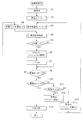
図7は、全てのGPS衛星、設定されたすべての周波数範囲に亘ってGPS衛星電波の探索を行う全検索処理におけるコントローラ156による制御手順を示したフローチャートである。また、図8は、図7内で呼び出される検出動作処理の制御手順を示すフローチャートである。
FIG. 7 is a flowchart showing a control procedure by the
この全検索処理は、例えば、衛星電波受信装置1の電源が初めてオンされたときに起動される。
This full search process is started when the power of the satellite
全検索処理が開始されると、先ず、コントローラ156は、メモリ157から最新の書込みアドレスnを取得する(ステップS1)。また、コントローラ156は、中間周波数生成器153にオフセット値として代入する値を示す初期受信チャンネルとして中心周波数チャンネルfcを設定する(ステップS2)。なお、中心周波数チャンネルfcの初期値としては、0が設定されている。更に、コントローラ156は、最初にシフトレジスタ1513eに記憶させるC/Aコードに対応するGPS衛星の識別番号として0〜3を設定する(ステップS3)。
When the full search process is started, first, the
ステップS1〜S3における変数の設定が完了すると、コントローラ156は、検出動作処理を呼び出して、GPS衛星から送信された信号の検出動作を行う(ステップS4)。具体的には、図8に示すように、コントローラ156は、先ず、逆拡散コード生成器154を動作させて、設定された衛星識別番号のC/Aコードをシフトレジスタ1513eに入力させる。それから、コントローラ156は、捕捉エンジン151全体に動作クロックを供給し、シフトレジスタ1513a、1513bにI/Q変換部1511および積分部1512で算出されたI相信号およびQ相信号をそれぞれ順番に格納させる。シフトレジスタ1513a、1513bのすべてのレジスタにデータが格納されると、コントローラ156は、次のデータがシフトレジスタ1513a、1513bに入力される前に、セレクタ1513fを操作して4衛星のC/Aコードを順番に出力させる。そして、コントローラ156は、それぞれのC/Aコードデータと入力された信号とに基づいて算出された加算器1514cの出力値を順番に取得し、メモリ157に記憶させる(ステップS41)。
When the setting of the variables in steps S1 to S3 is completed, the
コントローラ156は、データがシフトレジスタ1513a、1513bにそれぞれ1個ずつ入力されて位相が1データ分変化するごとにセレクタ1513fを操作して4衛星のC/Aコードを順番に出力させる。そして、コントローラ156は、捕捉エンジン151に4衛星のC/Aコードと入力された信号とに基づく計算を行わせ、メモリ157における当該位相のアドレスへ順番にデータを記憶させていく。設定された4衛星および受信チャンネルfに対する全ての位相のデータが取得されると、コントローラ156は、設定された4機のGPS衛星ごとに、設定された受信チャンネルfにおける全位相の出力値の中から最大のものを選択する(ステップS42)。それから、コントローラ156は、選択された最大の出力値以外の他の出力値の平均値をそれぞれ算出し(ステップS43)、算出されたこれらの平均値(ノイズレベル)に対する最大出力値の比をS/N比の値として算出する(ステップS44)。S/N値が算出されると、コントローラ156は、検出動作処理を終了して全検索処理へ戻る。
The
検出動作処理(ステップS4)が終了すると、次に、コントローラ156は、算出されたS/N値がそれぞれ設定された閾値aより大きいか否かを判別する(ステップS5)。算出されたS/N値が何れも設定された閾値a以下であると判別された場合には、コントローラ156による処理は、ステップS8へ移行する。算出されたS/N値のうち何れかが設定された閾値aより大きいと判別された場合には、コントローラ156は、閾値aより大きいと判別された値ごとにメモリ157のアドレスnの位置へ受信チャンネルfと算出されたS/N値sとを格納する(ステップS6)。また、コントローラ156は、アドレスnに1加算する(ステップS7)。それから、コントローラ156の処理は、ステップS8へ移行する。
When the detection operation process (step S4) ends, the
ステップS8へ移行すると、コントローラ156は、設定されている衛星識別番号が28〜31であるか否かを判別する。設定されている衛星識別番号が28〜31ではないと判別された場合には、コントローラ156は、設定されている4個の衛星識別番号にそれぞれ4を加算する(ステップS9)。それから、コントローラ156は、ステップS4〜S8の処理を繰り返す。
In step S8, the
ステップS8の判別処理で、設定されている衛星識別番号が28〜31であると判別された場合には、続いて、コントローラ156は、設定されている受信チャンネルが中心周波数チャンネルfc−150であるか否かを判別する(ステップS10)。
If it is determined in step S8 that the set satellite identification number is 28 to 31, the
ステップS10の判別処理で、設定されている受信チャンネルが中心周波数チャンネルfc−150ではないと判別された場合には、次に、コントローラ156は、設定されている受信チャンネルが中心周波数チャンネルfc以下であるか否かを判別する(ステップS11)。設定されている受信チャンネルが中心周波数チャンネルfc以下であると判別された場合には、コントローラ156は、次の受信チャンネルの設定を「2fc−現在の受信チャンネル+1」で求められるチャンネルに設定する(ステップS12)。そして、コントローラ156は、ステップS3〜S11の処理を繰り返す。一方、設定されている受信チャンネルが中心周波数チャンネルfcより大きいと判別された場合には、コントローラ156は、次の受信チャンネルの設定を「2fc−現在の受信チャンネル」で求められるチャンネルに設定する。そして、コントローラ156は、ステップS3〜S10の処理を繰り返す。即ち、ステップS10〜S13の処理において、受信チャンネルは、「fc」→「fc+1」→「fc−1」→「fc+2」→「fc−2」→…→「fc+150」→「fc−150」という順番で中心周波数チャンネルfcから徐々に離れていくように設定される。
If it is determined in step S10 that the set reception channel is not the center frequency channel fc-150, the
ステップS10の判別処理で、設定されている受信チャンネルが中心周波数チャンネルfc−150であると判別された場合には、コントローラ156の処理は、ステップS14に移行する。そして、コントローラ156は、次回の中心周波数チャンネルfcを算出してメモリ157に記憶させ、全検索処理を終了する。
If it is determined in the determination process of step S10 that the set reception channel is the center frequency channel fc-150, the process of the
図9は、GPS衛星からの電波のうち何れか一つを探索する検出処理におけるコントローラ156による制御手順を示したフローチャートである。
FIG. 9 is a flowchart showing a control procedure by the
この検出処理は、全検索処理がなされた後に、例えば、1日に一回予め定められた時刻に自動的に呼び出されて開始される処理である。 This detection process is a process that is automatically called and started at a predetermined time, for example, once a day after all the search processes are performed.
検出処理が開始されると、先ず、コントローラ156は、メモリ157から最新の書込みアドレスnを取得する(ステップS21)。また、コントローラ156は、中間周波数生成器153にオフセット値として代入する値を示す初期受信チャンネルとして中心周波数チャンネルfcを設定する(ステップS22)。この中心周波数チャンネルfcは、前回の検出処理か、又は、全検索処理により予め設定されている値である。更に、コントローラ156は、最初にシフトレジスタ1513eに記憶させるC/Aコードに対応するGPS衛星の識別番号として0〜3を設定する(ステップS23)。
When the detection process is started, first, the
ステップS21〜S23における変数の設定が完了すると、コントローラ156は、検出動作処理を呼び出して、GPS衛星から送信された信号の検出動作を行う(ステップS24)。具体的には、図8に示すように、コントローラ156は、先ず、逆拡散コード生成器154を動作させて、設定された衛星識別番号のC/Aコードをシフトレジスタ1513eに入力させる。それから、コントローラ156は、捕捉エンジン151全体に動作クロックを供給し、シフトレジスタ1513a、1513bにI/Q変換部1511および積分部1512で算出されたI相信号およびQ相信号をそれぞれ順番に格納させる。シフトレジスタ1513a、1513bのすべてのレジスタにデータが格納されると、コントローラ156は、次のデータがシフトレジスタ1513a、1513bに入力される前に、セレクタ1513fを操作して4衛星のC/Aコードを順番に出力させる。そして、コントローラ156は、それぞれのC/Aコードデータと入力された信号とに基づいて算出された加算器1514cの出力値を順番に取得し、メモリ157に記憶させる(ステップS41)。
When the setting of the variables in steps S21 to S23 is completed, the
コントローラ156は、データがシフトレジスタ1513a、1513bにそれぞれ1個ずつ入力されて位相が1データ分変化するごとにセレクタ1513fを操作して4衛星のC/Aコードを順番に出力させる。そして、コントローラ156は、捕捉エンジン151に4衛星のC/Aコードと入力された信号とに基づく計算を行わせ、メモリ157における当該位相のアドレスへ順番にデータを記憶させていく。設定された4衛星および受信チャンネルfに対する全ての位相のデータが取得されると、コントローラ156は、設定された4機のGPS衛星ごとに、設定された受信チャンネルfにおける全位相の出力値の中から最大のものを選択する(ステップS42)。それから、コントローラ156は、選択された最大の出力値以外の他の出力値の平均値をそれぞれ算出し(ステップS43)、算出されたこれらの平均値(ノイズレベル)に対する最大出力値の比をS/N比の値として算出する(ステップS44)。S/N値が算出されると、コントローラ156は、検出動作処理を終了して検出処理へ戻る。
The
検出動作処理(ステップS24)が終了すると、次に、コントローラ156は、算出されたS/N値が、それぞれ設定された閾値aより大きいか否かを判別する(ステップS25)。算出されたS/N値が何れも設定された閾値a以下であると判別された場合には、コントローラ156による処理は、ステップS28へ移行する。コントローラ156は、設定されている衛星識別番号が28〜31であるか否かを判別する。設定されている衛星識別番号が28〜31ではないと判別された場合には、コントローラ156は、設定されている4個の衛星識別番号にそれぞれ4を加算する(ステップS29)。それから、コントローラ156は、ステップS24、S25の処理を繰り返す。
When the detection operation process (step S24) is completed, the
ステップS28の判別処理で、設定されている衛星識別番号が28〜31であると判別された場合には、続いて、コントローラ156は、設定されている受信チャンネルが中心周波数チャンネルfc−150であるか否かを判別する(ステップS30)。
If it is determined in step S28 that the set satellite identification number is 28 to 31, the
ステップS30の判別処理で、設定されている受信チャンネルが中心周波数チャンネルfc−150ではないと判別された場合には、次に、コントローラ156は、設定されている受信チャンネルが中心周波数チャンネルfc以下であるか否かを判別する(ステップS31)。設定されている受信チャンネルが中心周波数チャンネルfc以下であると判別された場合には、コントローラ156は、次の受信チャンネルの設定を「2fc−現在の受信チャンネル+1」で求められるチャンネルに設定する(ステップS32)。そして、コントローラ156は、ステップS23へ戻って検出動作処理を繰り返す。一方、設定されている受信チャンネルが中心周波数チャンネルfcより大きいと判別された場合には、コントローラ156は、次の受信チャンネルの設定を「2fc−現在の受信チャンネル」で求められるチャンネルに設定する。そして、コントローラ156は、ステップS23〜S25の処理を繰り返す。即ち、ステップS30〜S33の処理において、受信チャンネルは、「fc」→「fc+1」→「fc−1」→「fc+2」→「fc−2」→…→「fc+150」→「fc−150」という順番で中心周波数チャンネルfcから徐々に離れていくように設定される。
If it is determined in step S30 that the set reception channel is not the center frequency channel fc-150, the
ステップS30の判別処理で、設定されている受信チャンネルが中心周波数チャンネルfc−150であると判別された場合には、コントローラ156の処理は、ステップS34に移行する。
If it is determined in step S30 that the set reception channel is the center frequency channel fc-150, the process of the
ステップS25の判別処理で、算出されたS/N値のうち何れかが設定された閾値aより大きいと判別された場合には、コントローラ156は、閾値aより大きいと判別された値ごとにメモリ157のアドレスnの位置へ受信チャンネルfと算出されたS/N値sとを格納する(ステップS26)。また、コントローラ156は、アドレスnに1加算する(ステップS27)。或いは、コントローラ156は、最先に設定された閾値a以上のS/N値が検出された受信チャンネルfと、当該S/N値sのみをアドレスnに格納することとしてもよい。それから、コントローラ156の処理は、ステップS34へ移行する。
When it is determined in the determination process in step S25 that any one of the calculated S / N values is larger than the set threshold value a, the
ステップS34へ移行すると、コントローラ156は、次回の中心周波数チャンネルfcを算出して検出処理を終了する。
In step S34, the
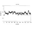
図10は、図9に示した検出処理を繰り返して行った場合に、メモリ157に記憶された最新の30個の受信チャンネルfに対するS/N値sの重み付け平均により求められた中心周波数チャンネルfcに対応する周波数と、次回の検出処理の際に衛星信号が検出された受信チャンネルfに対応する周波数との差の遷移をシミュレーションにより求めた結果を示す図である。
FIG. 10 shows the center frequency channel fc obtained by the weighted average of the S / N values s for the latest 30 reception channels f stored in the
検出処理により求められた中心周波数チャンネルfcと次回の検出処理で衛星信号が検出された受信チャンネルfとの差は、ほぼ0.7kHzの範囲内に収まっている。即ち、多くとも15回程度の受信チャンネルfの変更処理により、GPS衛星のうちの何れかからの電波を受信することができることが示されている。 The difference between the center frequency channel fc obtained by the detection process and the reception channel f from which the satellite signal is detected in the next detection process is within a range of approximately 0.7 kHz. That is, it is shown that the radio wave from any of the GPS satellites can be received by changing the reception channel f about 15 times at most.
以上のように、本発明の実施形態の衛星電波受信装置1によれば、受信周波数と受信対象とする測位用衛星とを順次切り換えながら測位用衛星からの衛星信号を探索する捕捉エンジン151と、捕捉エンジン151により検出された複数の衛星信号の受信周波数から中心周波数を算出するコントローラ156とを備え、次回、衛星信号を探索する際には、この中心周波数から衛星信号の検出を開始するので、測位用衛星の移動によるドップラー効果および衛星電波受信装置1の発振周波数オフセットの両方の影響を考慮した適切な受信周波数から素早く衛星信号を検出することができる。
As described above, according to the satellite
また、素早く衛星信号を検出することで、受信動作および検出動作の時間を短縮することができるので、電力消費量を低減させることができる。 In addition, since the time for the reception operation and the detection operation can be shortened by quickly detecting the satellite signal, the power consumption can be reduced.
また、複数の衛星信号の受信周波数と受信強度(S/N値)とを関連付けてメモリ157に記憶させ、受信強度によって重み付けを行った受信周波数の平均値により中心周波数を決定するので、受信条件の良い衛星信号を素早く検出しやすい。
Further, the reception frequency and the reception intensity (S / N value) of a plurality of satellite signals are stored in the
また、中心周波数を利用して衛星信号の探索を行う際には、中心周波数から徐々に離れた受信周波数に変更していくので、受信条件の良い測位用衛星が優先的に検出しやすい。 Further, when searching for a satellite signal using the center frequency, since the reception frequency is gradually changed from the center frequency, a positioning satellite with good reception conditions is easily detected with priority.
また、中心周波数を中心にして定められた範囲内の周波数で衛星信号の探索を行うので、例えば、衛星電波受信装置1の発振周波数オフセットの影響による受信不可能な周波数帯での衛星信号の探索を行う無駄を省くことができる。また、日常的に検出処理を行う場所の上空が建築物といった遮蔽物によって一部の方向のみに限られているような場合でも、受信できる方向のGPS衛星に対するドップラー効果の影響を考慮して中心周波数を求め、この中心周波数を中心にして定められた範囲内の周波数で衛星信号の探索を行うので、実際に受信可能な方向が決まっている場合にも効率よく受信のできる周波数で探索を行うことができる。
In addition, since the search for the satellite signal is performed at a frequency within a range determined around the center frequency, for example, the search for the satellite signal in a frequency band that cannot be received due to the influence of the oscillation frequency offset of the satellite
また、衛星電波受信装置1によって検出された衛星信号のうち、最新の30回の受信周波数および受信強度に基づいて中心周波数を算出するので、季節による温度変化や測位用衛星の軌道の変化といった影響を徐々に反映させながら検出精度を落とさずに衛星信号を素早く検出することができる。
In addition, since the center frequency is calculated based on the latest 30 received frequencies and received strengths among the satellite signals detected by the satellite
更に、受信強度の指標をノイズレベルに対する強度比とすることによって、1回の衛星信号の検出データの重みのばらつきを極度に偏らせずに安定して中心周波数を算出することができる。 Furthermore, by setting the reception intensity index as the intensity ratio with respect to the noise level, it is possible to calculate the center frequency stably without extremely biasing the variation in the weight of the detection data of one satellite signal.
なお、本発明は、上記実施の形態に限られるものではなく、様々な変更が可能である。例えば、上記実施の形態では、全検索処理は、衛星電波受信装置1の最初の起動時に実行されたが、実施時期はこれに限られず、また、一度に限られない。例えば、工場における製品出荷前の調整、検査時に実行させることも可能である。或いは、GPS測位機能を利用して位置情報を取得する際に毎回全検索処理を行わせても良いし、取得した位置情報が前回取得した位置情報と大きく異なる場合や、南北半球間や異なる緯度の地点に移動して季節や気候の変化により温度が大きく変化するような場合などに、この全検索処理を起動させるたりするように設定することも可能である。
The present invention is not limited to the above-described embodiment, and various modifications can be made. For example, in the above embodiment, the entire search process is executed when the satellite
また、上記の全検索処理を定期的に行わせても良いし、或いは、例えば、受信チャンネルの範囲を狭めた全検索処理を実行させたり、S/N比の閾値レベルを上昇させた検出処理を実行させたりといった動作と組み合わせてメモリ157の各アドレスに記憶させる受信情報の精度を向上させることも可能である。
In addition, the above-described all search processing may be performed periodically, or, for example, the entire search processing in which the range of the reception channel is narrowed or the detection processing in which the threshold level of the S / N ratio is increased It is also possible to improve the accuracy of received information stored in each address of the
また、上記実施の形態では、毎回GPS衛星からの衛星信号が検出されるごとに検出された受信周波数をメモリ157に記憶させたが、発振回路の周波数オフセットの値は、温度に依存して変化することが知られている。従って、例えば、発振回路の近傍に温度センサを配置し、この温度センサの計測データに基づいて受信周波数を補正することにより、中心周波数を設定する際に一時的な温度変化の影響を除外するように衛星電波受信装置1を構成することもできるし、或いは、単純に、温度センサの計測値をコントローラ156に監視させ、時刻データを取得する際にこの計測値が大きく変化している場合には、全検索処理を実行させることとしても良い。
In the above embodiment, the received frequency detected each time a satellite signal from a GPS satellite is detected is stored in the
また、上記実施の形態では、コントローラ156およびメモリ157をベースバンド部15の内部に配置して利用したが、衛星電波受信装置1の全体を統括するCPUや一時データを記憶するRAMを備えたマイクロコンピュータを用いることとしても良い。また、演算処理部155で用いられるCPUとコントローラ156のCPUは、同一であっても良い。
In the above-described embodiment, the
また、上記実施の形態では、GPSによるL1帯電波の受信の際の処理について説明したが、L2帯などの他の受信処理にも適用可能であり、また、GLONASS(Global Navigation Satellite System)、および、GALILEOといった他の測位衛星システムを利用する場合に適用することもできる。その他、上記実施の形態で示した同時並列的に検索を行うGPS衛星データの数、各部の入出力周波数や、メモリのビット数といった具体的な数値、および、具体的な構成や配置といった細部は、発明の趣旨を逸脱しない限りにおいて適宜変更可能である。 Further, in the above embodiment, the processing at the time of receiving the L1 charged wave by GPS has been described. However, the present invention can be applied to other receiving processing such as the L2 band, GLONASS (Global Navigation Satellite System), and It can also be applied when using other positioning satellite systems such as GALILEO. Other details such as the number of GPS satellite data to be searched in parallel in the above embodiment, specific numerical values such as the input / output frequency of each part, the number of bits of memory, and specific configuration and arrangement are as follows. Any change can be made without departing from the spirit of the invention.
1 衛星電波受信装置
11 低雑音増幅器
12 狭帯域フィルタ
13 発振回路
14 RF部
141 ダウンコンバータ
142 PLL
143 ADC
15 ベースバンド部
151 捕捉エンジン
1511 I/Q変換部
1511a、1511b ミキサ
1512 積分部
1512a、1512b 積分器
1513 相関器
1513a、1513b、1513e シフトレジスタ
1513c、1513d 加算器
1513f セレクタ
1514 二乗回路
1514a、1514b 二乗計算部
1514c 加算器
152 追尾エンジン
153 中間周波数生成器
1531、1532 加算器
1533 レジスタ
1534 COS ROM
1535 SIN ROM
154 逆拡散コード生成器
155 演算処理部
156 コントローラ
157 メモリ
ANT 受信アンテナ
f 受信チャンネル
fc 中心周波数チャンネル
fi 中間周波数
Δf 周波数変化量
s S/N値
DESCRIPTION OF
143 ADC
15
1535 SIN ROM
154
Claims (7)
前記測位用衛星が送信する周波数を含む予め設定された周波数範囲の電波を受信可能な受信手段と、
前記受信手段により受信された電波に基づく受信信号から前記衛星信号を検出する捕捉手段と、
前記捕捉手段により検出された複数の前記衛星信号の受信周波数に基づいて、当該検出された複数の前記衛星信号の中心周波数を算出する算出手段と、
を備え、
前記捕捉手段は、前記中心周波数を基準として前記衛星信号の検出を行う
ことを特徴とする衛星電波受信装置。 In the satellite radio wave receiver that acquires the satellite signal transmitted from the positioning satellite,
Receiving means capable of receiving radio waves in a preset frequency range including the frequency transmitted by the positioning satellite;
Capturing means for detecting the satellite signal from a received signal based on the radio wave received by the receiving means;
Calculation means for calculating center frequencies of the detected plurality of satellite signals based on reception frequencies of the plurality of satellite signals detected by the acquisition means;
With
The satellite radio wave receiving apparatus characterized in that the capturing means detects the satellite signal with reference to the center frequency.
前記算出手段は、前記記憶手段に記憶された複数の前記衛星信号に係る前記受信周波数の前記強度指標による重み付平均により前記中心周波数を算出する
ことを特徴とする請求項1記載の衛星電波受信装置。 Storage means for associating and storing the reception frequency of the satellite signal detected by the acquisition means and an intensity index indicating the signal intensity of the satellite signal at the reception frequency;
2. The satellite radio wave reception according to claim 1, wherein the calculation unit calculates the center frequency by a weighted average based on the intensity index of the reception frequencies related to the plurality of satellite signals stored in the storage unit. apparatus.
ことを特徴とする請求項1又は2記載の衛星電波受信装置。 The capturing means detects the satellite signal while changing the reception frequency so that the deviation between the center frequency and the reception frequency for detecting the satellite signal increases from zero. The satellite radio wave receiver according to claim 1 or 2.
ことを特徴とする請求項1〜3の何れか一項に記載の衛星電波受信装置。 The satellite radio wave receiving apparatus according to any one of claims 1 to 3, wherein the capturing unit detects the satellite signal over a predetermined frequency range centered on the center frequency. .
ことを特徴とする請求項2記載の衛星電波受信装置。 The storage means can store a predetermined number of the reception frequencies and the intensity index, and among the satellite signals detected by the acquisition means, the latest predetermined number of the reception frequencies and The satellite radio wave receiver according to claim 2, wherein the intensity index is stored.
ことを特徴とする請求項2記載の衛星電波受信装置。 The intensity index is a ratio of a signal intensity when the satellite signal is detected at the reception frequency where the satellite signal is detected and an average signal intensity when the satellite signal is not detected at the reception frequency. The satellite radio wave receiver according to claim 2, wherein the satellite radio wave receiver is provided.
前記受信手段により受信された電波に基づく受信信号から前記衛星信号を検出する捕捉ステップと、
前記捕捉ステップで検出された複数の前記衛星信号の受信周波数に基づいて、当該検出された複数の前記衛星信号の中心周波数を算出する算出ステップと、
を含み、
前記捕捉ステップは、前記中心周波数を基準として前記衛星信号の検出を行う
ことを特徴とする衛星電波受信方法。 In a satellite radio wave receiving method comprising a receiving means for receiving a radio wave transmitted from a positioning satellite, and acquiring a satellite signal from the radio wave received by the receiving means,
A capturing step of detecting the satellite signal from a received signal based on the radio wave received by the receiving means;
A calculation step of calculating center frequencies of the detected plurality of satellite signals based on reception frequencies of the plurality of satellite signals detected in the acquisition step;
Including
The satellite radio wave reception method, wherein the capturing step detects the satellite signal with reference to the center frequency.
Priority Applications (3)
| Application Number | Priority Date | Filing Date | Title |
|---|---|---|---|
| JP2010219006A JP5110141B2 (en) | 2010-09-29 | 2010-09-29 | Satellite radio wave receiving apparatus and satellite radio wave receiving method |
| US13/239,883 US8570218B2 (en) | 2010-09-29 | 2011-09-22 | Satellite radiowave receiver and satellite radiowave receiving method |
| CN201110335798.1A CN102540201B (en) | 2010-09-29 | 2011-09-28 | Satellite radiowave receiver and satellite radiowave receiving method |
Applications Claiming Priority (1)
| Application Number | Priority Date | Filing Date | Title |
|---|---|---|---|
| JP2010219006A JP5110141B2 (en) | 2010-09-29 | 2010-09-29 | Satellite radio wave receiving apparatus and satellite radio wave receiving method |
Publications (2)
| Publication Number | Publication Date |
|---|---|
| JP2012073156A JP2012073156A (en) | 2012-04-12 |
| JP5110141B2 true JP5110141B2 (en) | 2012-12-26 |
Family
ID=45870098
Family Applications (1)
| Application Number | Title | Priority Date | Filing Date |
|---|---|---|---|
| JP2010219006A Active JP5110141B2 (en) | 2010-09-29 | 2010-09-29 | Satellite radio wave receiving apparatus and satellite radio wave receiving method |
Country Status (3)
| Country | Link |
|---|---|
| US (1) | US8570218B2 (en) |
| JP (1) | JP5110141B2 (en) |
| CN (1) | CN102540201B (en) |
Families Citing this family (10)
| Publication number | Priority date | Publication date | Assignee | Title |
|---|---|---|---|---|
| US20110228810A1 (en) * | 2010-02-09 | 2011-09-22 | O'hara Gary | Multiple object talking non-contact thermometer |
| US8712359B2 (en) | 2012-08-23 | 2014-04-29 | Intel Mobile Communications GmbH | Communication device and method for detecting a radio signal |
| US10845452B2 (en) | 2013-05-08 | 2020-11-24 | Cm Hk Limited | Hybrid positioning method, electronic apparatus and computer-readable recording medium thereof |
| JP6427985B2 (en) * | 2013-08-29 | 2018-11-28 | セイコーエプソン株式会社 | Electronic clock |
| CN104423271B (en) * | 2013-09-06 | 2017-12-19 | 精工爱普生株式会社 | The satellite signal reception method of electronic watch and electronic watch |
| JP6432164B2 (en) * | 2014-05-30 | 2018-12-05 | カシオ計算機株式会社 | Spread spectrum signal receiver and clock device |
| JP6206478B2 (en) * | 2015-12-24 | 2017-10-04 | カシオ計算機株式会社 | Satellite radio wave receiver, radio wave clock, code signal acquisition method and program |
| TWI622783B (en) * | 2016-05-24 | 2018-05-01 | 曦恩體感科技股份有限公司 | Hybrid positioning method and electronic device thereof |
| CN115327582B (en) * | 2022-10-13 | 2023-02-14 | 北京凯芯微科技有限公司 | GNSS signal processing circuit, method and receiver |
| CN119414101B (en) * | 2024-11-01 | 2026-01-27 | 国网湖北省电力有限公司电力科学研究院 | Power secondary line phase measurement and verification method based on Beidou clock synchronization |
Family Cites Families (14)
| Publication number | Priority date | Publication date | Assignee | Title |
|---|---|---|---|---|
| US4701934A (en) * | 1985-09-03 | 1987-10-20 | Motorola, Inc. | Method of doppler searching in a digital GPS receiver |
| US5177490A (en) * | 1989-12-12 | 1993-01-05 | Pioneer Electronic Corporation | Gps satellite signal tracking system for gps receivers |
| US5323164A (en) * | 1992-03-16 | 1994-06-21 | Pioneer Electronic Corporation | Satellite radio wave capturing method for a global positioning system (GPS) receiver |
| JP3210060B2 (en) * | 1992-03-18 | 2001-09-17 | パイオニア株式会社 | Setting method of search center frequency in GPS receiver |
| US6114992A (en) * | 1997-05-22 | 2000-09-05 | Conexant Systems, Inc. | Satellite acquisition and measurement system and process |
| US6195328B1 (en) * | 1998-04-15 | 2001-02-27 | The United States Of America As Represented By The Secretary Of The Air Force | Block adjustment of synchronizing signal for phase-coded signal tracking |
| CN1360804A (en) * | 1999-05-06 | 2002-07-24 | 塞-洛克公司 | Wireless location system |
| US6522871B1 (en) * | 2000-05-09 | 2003-02-18 | Qualcomm, Incorporated | Method and apparatus for compensating local oscillator frequency error through environmental control |
| WO2002054537A1 (en) * | 2000-12-30 | 2002-07-11 | Genghiscomm, Llc | Carrier interferometry coding and multicarrier processing |
| US20050063487A1 (en) * | 2001-05-08 | 2005-03-24 | Soheil Sayegh | Method and apparatus for parameter estimation, modulation classification and interference characterization in satellite communication systems |
| US6903684B1 (en) * | 2002-10-22 | 2005-06-07 | Qualcomm Incorporated | Method and apparatus for optimizing GPS-based position location in presence of time varying frequency error |
| US7362795B1 (en) * | 2004-03-28 | 2008-04-22 | Trimble Navigation Ltd | Method and apparatus for acquisition and tracking of GPS satellites at low signal to noise levels |
| JP2008032637A (en) | 2006-07-31 | 2008-02-14 | Seiko Epson Corp | Time correction device, time measuring device with time correction device, and time correction method |
| JP5145670B2 (en) | 2006-08-22 | 2013-02-20 | セイコーエプソン株式会社 | Time correction device, electronic timepiece with time correction device, and time correction method |
-
2010
- 2010-09-29 JP JP2010219006A patent/JP5110141B2/en active Active
-
2011
- 2011-09-22 US US13/239,883 patent/US8570218B2/en active Active
- 2011-09-28 CN CN201110335798.1A patent/CN102540201B/en active Active
Also Published As
| Publication number | Publication date |
|---|---|
| US20120075143A1 (en) | 2012-03-29 |
| US8570218B2 (en) | 2013-10-29 |
| JP2012073156A (en) | 2012-04-12 |
| CN102540201A (en) | 2012-07-04 |
| CN102540201B (en) | 2014-07-30 |
Similar Documents
| Publication | Publication Date | Title |
|---|---|---|
| JP5110141B2 (en) | Satellite radio wave receiving apparatus and satellite radio wave receiving method | |
| JP5687632B2 (en) | Local clock frequency calibration using low earth orbit (LEO) satellites | |
| US6496145B2 (en) | Signal detector employing coherent integration | |
| EP2093584B1 (en) | Processing received satellite radio signals | |
| CN101441259B (en) | A self-assisted tracking system and tracking method for a global positioning system receiver | |
| JP2004501352A (en) | Signal detector and method employing a coherent accumulation system for correlating non-uniform and discrete sample segments | |
| US8779973B2 (en) | Satellite signal tracking method, position calculating method, and position calculating device | |
| CN103033831B (en) | Satellite radiowave receiving device | |
| US9354320B2 (en) | Method of determining adequacy and adequacy determining device | |
| JP2008510163A (en) | Apparatus, method and computer program for acquiring GPS signals using an adaptive search engine | |
| US8953721B2 (en) | Cross correlation determination method and cross correlation determination device | |
| JP6047944B2 (en) | Receiver and correlation integration processing method | |
| CN102650695B (en) | Satellite radio receiver | |
| JP5267478B2 (en) | Satellite signal tracking method and position calculation apparatus | |
| US8351470B2 (en) | Signal receiver, control method of signal receiver, and GPS device utilizing the signal receiver and method | |
| JP2011164088A (en) | Method for tracking satellite signal, method for calculating position, device for tracking satellite signal and device for calculating position | |
| KR20040105258A (en) | Aiding in a satellite positioning system | |
| JP2007017184A (en) | Device for transmitting positioning signal, positioning system equipped with such device, and system for transmitting positioning signal | |
| JPH1048312A (en) | Satellite receiving device and satellite receiving system |
Legal Events
| Date | Code | Title | Description |
|---|---|---|---|
| A977 | Report on retrieval |
Free format text: JAPANESE INTERMEDIATE CODE: A971007 Effective date: 20120906 |
|
| TRDD | Decision of grant or rejection written | ||
| A01 | Written decision to grant a patent or to grant a registration (utility model) |
Free format text: JAPANESE INTERMEDIATE CODE: A01 Effective date: 20120911 |
|
| A01 | Written decision to grant a patent or to grant a registration (utility model) |
Free format text: JAPANESE INTERMEDIATE CODE: A01 |
|
| A61 | First payment of annual fees (during grant procedure) |
Free format text: JAPANESE INTERMEDIATE CODE: A61 Effective date: 20120924 |
|
| FPAY | Renewal fee payment (event date is renewal date of database) |
Free format text: PAYMENT UNTIL: 20151019 Year of fee payment: 3 |
|
| R150 | Certificate of patent or registration of utility model |
Ref document number: 5110141 Country of ref document: JP Free format text: JAPANESE INTERMEDIATE CODE: R150 Free format text: JAPANESE INTERMEDIATE CODE: R150 |