JP5108552B2 - Vehicle control device and saddle riding type vehicle - Google Patents

Vehicle control device and saddle riding type vehicle Download PDF

Info

Publication number
JP5108552B2
JP5108552B2 JP2008037433A JP2008037433A JP5108552B2 JP 5108552 B2 JP5108552 B2 JP 5108552B2 JP 2008037433 A JP2008037433 A JP 2008037433A JP 2008037433 A JP2008037433 A JP 2008037433A JP 5108552 B2 JP5108552 B2 JP 5108552B2
Authority
JP
Japan
Prior art keywords
vehicle
warning
processing unit
control device
vehicle control
Prior art date
Legal status (The legal status is an assumption and is not a legal conclusion. Google has not performed a legal analysis and makes no representation as to the accuracy of the status listed.)
Active
Application number
JP2008037433A
Other languages
Japanese (ja)
Other versions
JP2009196407A (en
Inventor
幸夫 伊藤
Current Assignee (The listed assignees may be inaccurate. Google has not performed a legal analysis and makes no representation or warranty as to the accuracy of the list.)
Yamaha Motor Co Ltd
Original Assignee
Yamaha Motor Co Ltd
Priority date (The priority date is an assumption and is not a legal conclusion. Google has not performed a legal analysis and makes no representation as to the accuracy of the date listed.)
Filing date
Publication date
Application filed by Yamaha Motor Co Ltd filed Critical Yamaha Motor Co Ltd
Priority to JP2008037433A priority Critical patent/JP5108552B2/en
Publication of JP2009196407A publication Critical patent/JP2009196407A/en
Application granted granted Critical
Publication of JP5108552B2 publication Critical patent/JP5108552B2/en
Active legal-status Critical Current
Anticipated expiration legal-status Critical

Links

Images

Description

本発明は、ユーザーが所持する携帯機との通信機能を有する車両制御装置、及び鞍乗型車両に関し、特に電源スイッチのオフ操作をユーザーに促す技術に関する。   The present invention relates to a vehicle control device and a saddle riding type vehicle having a communication function with a portable device possessed by a user, and more particularly to a technique for prompting a user to turn off a power switch.

近年、自動二輪車などの鞍乗型車両において、ユーザーによって所持される携帯機と、車体に搭載される車両制御装置とを含むキーレスエントリーシステムが利用されている。このようなキーレスエントリーシステムでは、携帯機には予め識別情報が設定されており、車両制御装置は携帯機と無線で通信して、その識別情報に基づいて携帯機について認証の処理を行う。そして、携帯機が認証された場合に、ユーザーによる車両の起動及び操作が許容される。   2. Description of the Related Art In recent years, a keyless entry system including a portable device carried by a user and a vehicle control device mounted on a vehicle body has been used in a saddle riding type vehicle such as a motorcycle. In such a keyless entry system, identification information is set in advance in the portable device, and the vehicle control device communicates wirelessly with the portable device and performs authentication processing on the portable device based on the identification information. And when a portable machine is authenticated, starting and operation of vehicles by a user are permitted.

このようなキーレスエントリーシステムを備える車両を駐車する際には、一般的に、ユーザーが車両の電源スイッチをオフしたり、電装品のスイッチをオフすることで、電源からECU等の各種電装品への電力供給が停止される。しかしながら、ユーザーがスイッチをオフすることを忘れたまま車両から立ち去ると、電源の電力が無駄に消費され、電源の残量が著しく低下する場合がある。   When a vehicle equipped with such a keyless entry system is parked, generally, the user turns off the power switch of the vehicle or turns off the switch of the electrical component, so that the power source switches to various electrical components such as an ECU. The power supply is stopped. However, if the user leaves the vehicle without forgetting to turn off the switch, the power of the power source is wasted and the remaining amount of the power source may be significantly reduced.

このような事態を防止する技術として、特許文献1には、エンジンが停止されると車両制御装置が携帯機との通信を試行し、通信が成功しない場合には、スイッチの切り忘れが生じたものと判断して、電源の電力供給を自動で停止する処理を行うシステムが開示されている。また、特許文献2には、同様の場合に、警告音を鳴らして、その旨をユーザーに通知するシステムが開示されている。
特許第2678502号公報 特開2007−269236号公報
As a technique for preventing such a situation, Patent Document 1 discloses that when the engine is stopped, the vehicle control device tries to communicate with the portable device, and when the communication is not successful, the switch is forgotten to be turned off. And a system that performs a process of automatically stopping the power supply of the power source is disclosed. Further, Patent Document 2 discloses a system that sounds a warning sound and notifies the user to that effect in the same case.
Japanese Patent No. 2678502 JP 2007-269236 A

しかしながら、車両の停止状態において携帯機との通信が成立する場合でも、電源の電力供給を停止したほうが良い場合がある。例えば、ユーザーが車両の近くにいるものの、車両を操作することなく、他の作業を行なっている場合には、無駄な電力消費を抑えるために、電源の電力供給は停止されることが望ましい。しかしながら、このような場合においても、上記従来技術では電力供給は継続される。   However, there are cases where it is better to stop the power supply of the power source even when communication with the portable device is established when the vehicle is stopped. For example, when the user is near the vehicle but is performing other work without operating the vehicle, it is desirable to stop the power supply of the power source in order to suppress wasteful power consumption. However, even in such a case, power supply is continued in the above-described conventional technology.

本発明は、上記課題に鑑みてなされたものであって、その目的は、より効果的に無駄な電力消費を抑えることのできる車両制御装置、及び鞍乗型車両を提供することにある。   The present invention has been made in view of the above problems, and an object of the present invention is to provide a vehicle control device and a straddle-type vehicle that can suppress wasteful power consumption more effectively.

上記課題を解決するために、本発明に係る車両制御装置は、電装品へ電力を供給する電源とともに車両に搭載され、ユーザーによって所持される携帯機と通信可能に設けられる車両制御装置であって、車両が停止しているか否かを判定する停止判定部と、前記携帯機との通信を試行する通信処理部と、車両の停止状態において前記電源の電力供給がオン状態にある場合であって、前記通信処理部による前記携帯機との通信が成功する場合に、車両に設けられた警告器を作動させる警告処理部とを備える。   In order to solve the above-described problem, a vehicle control device according to the present invention is a vehicle control device that is mounted on a vehicle together with a power source that supplies electric power to an electrical component and is provided so as to be communicable with a portable device possessed by a user. A stop determination unit that determines whether or not the vehicle is stopped, a communication processing unit that tries to communicate with the portable device, and a power supply of the power source in an on state when the vehicle is stopped. A warning processing unit that activates a warning device provided in the vehicle when communication with the portable device by the communication processing unit is successful.

また、上記課題を解決するために、本発明に係る鞍乗型車両は上記車両制御装置を備える。   In order to solve the above problems, a straddle-type vehicle according to the present invention includes the vehicle control device.

本発明によれば、ユーザーが車両の近くにいる場合においても、電源の電力供給の停止をユーザーに促すことができので、無駄な電力消費をより効果的に抑えることができる。なお、ここで鞍乗型車両は、ユーザーがシートに跨って座る車両であり、例えば、自動二輪車(スクーターを含む)や、二輪電動車、四輪バギー、スノーモービル等である。   According to the present invention, even when the user is in the vicinity of the vehicle, the user can be prompted to stop the power supply of the power source, so that wasteful power consumption can be more effectively suppressed. Here, the saddle riding type vehicle is a vehicle on which a user sits across a seat, and is, for example, a motorcycle (including a scooter), a two-wheeled electric vehicle, a four-wheel buggy, a snowmobile, or the like.

以下、本発明の一実施形態について図面を参照しながら説明する。図1は本発明の実施形態の例である車両制御装置1を備える自動二輪車100の概略の側面図であり、図2は当該自動二輪車100が備える装置のブロック図である。   Hereinafter, an embodiment of the present invention will be described with reference to the drawings. FIG. 1 is a schematic side view of a motorcycle 100 including a vehicle control apparatus 1 which is an example of an embodiment of the present invention. FIG. 2 is a block diagram of an apparatus included in the motorcycle 100.

なお、自動二輪車100は、所謂キーレスエントリーシステムを備えた車両であり、ユーザーによって所持される携帯機30を認証するための処理を実行する。当該処理において携帯機30が認証される場合に、エンジンの始動等の車両の作動が許容される。携帯機30には固有の識別情報が割り当てられており、携帯機30は、識別情報の送信を要求する信号を自動二輪車100から受信した場合に、予め記憶している識別情報を返信する。自動二輪車100では、携帯機30から返信された識別情報と、予め自動二輪車100側で記憶している識別情報が一致するか否かを判定することで、携帯機30を認証するための処理を行う。   The motorcycle 100 is a vehicle having a so-called keyless entry system, and executes a process for authenticating the portable device 30 possessed by the user. When the portable device 30 is authenticated in the process, the operation of the vehicle such as the start of the engine is allowed. Unique identification information is assigned to the portable device 30. When the portable device 30 receives a signal requesting transmission of the identification information from the motorcycle 100, the portable device 30 returns the identification information stored in advance. In the motorcycle 100, a process for authenticating the portable device 30 is performed by determining whether or not the identification information returned from the portable device 30 matches the identification information stored in advance on the motorcycle 100 side. Do.

図1又は図2に示すように、自動二輪車100は、車両制御装置1の他に、エンジン2と、前輪3と、後輪4と、バッテリ41とを備えている。車両制御装置1は、電源制御装置10と、ECU(Electronic Control Unit)20とを含んでいる。   As shown in FIG. 1 or 2, the motorcycle 100 includes an engine 2, a front wheel 3, a rear wheel 4, and a battery 41 in addition to the vehicle control device 1. The vehicle control device 1 includes a power supply control device 10 and an ECU (Electronic Control Unit) 20.

図1に示すように、前輪3は車体前部に配置されたフロントフォーク8によって支持されている。フロントフォーク8の上方にはハンドル5が配置され、当該ハンドル5は、ユーザーのハンドル操作に応じて、フロントフォーク8及び前輪3と一体的に回転可能に設けられている。エンジン2は車体下部に配置され、その内部で燃料を燃焼させることによって駆動する。エンジン2の駆動力は変速機等を含む伝達ユニット9を介して後輪4に伝達される。また、自動二輪車100では、エンジン2の上方に搭乗者が跨って座るためのシート6が配置され、車体中央の下部には、車体を立った姿勢で支持するためのスタンド7が配置されている。スタンド7は、その使用時には、ユーザーによって地面に対して立てられて、車体を支持し、その不使用時には車体側に上げられる。   As shown in FIG. 1, the front wheel 3 is supported by a front fork 8 disposed at the front of the vehicle body. A handle 5 is disposed above the front fork 8, and the handle 5 is provided so as to be rotatable integrally with the front fork 8 and the front wheel 3 in response to a user's handle operation. The engine 2 is disposed at the lower part of the vehicle body and is driven by burning fuel therein. The driving force of the engine 2 is transmitted to the rear wheel 4 via a transmission unit 9 including a transmission and the like. Further, in the motorcycle 100, a seat 6 for a passenger to sit on top of the engine 2 is disposed, and a stand 7 for supporting the vehicle body in a standing posture is disposed in the lower part of the center of the vehicle body. . The stand 7 is stood against the ground by the user when used, and supports the vehicle body, and is raised to the vehicle body side when not used.

バッテリ41は、エンジン2の駆動によって発電する発電機(不図示)に接続されており、当該発電機によって充電される。バッテリ41は、蓄えた電力をECU20や電源制御装置10、不図示の灯火器等に供給する。図2に示すように、バッテリ41は電源制御装置10とECU20のそれぞれに接続され、ECU20とバッテリ41との間にはリレー回路42が設けられている。   The battery 41 is connected to a generator (not shown) that generates electricity by driving the engine 2 and is charged by the generator. The battery 41 supplies the stored power to the ECU 20, the power supply control device 10, a lighting device (not shown), and the like. As shown in FIG. 2, the battery 41 is connected to each of the power supply control device 10 and the ECU 20, and a relay circuit 42 is provided between the ECU 20 and the battery 41.

ECU20の構成について説明する。図2に示すように、ECU20は、制御部21と、記憶部22と、電源回路23と、エンジン駆動回路24と、入力回路25と、通信インターフェース部26とを備え、リレー回路42を介してバッテリ41から供給される電力によって動作する。   The configuration of the ECU 20 will be described. As shown in FIG. 2, the ECU 20 includes a control unit 21, a storage unit 22, a power supply circuit 23, an engine drive circuit 24, an input circuit 25, and a communication interface unit 26, via a relay circuit 42. It operates with electric power supplied from the battery 41.

記憶部22はRAM(Random Access Memory)やROM(Read Only Memory)を含んでおり、制御部21によって実行されるプログラムを予め記憶している。制御部21は、マイクロプロセッサを含み、記憶部22に格納されているプログラムに従って動作して、エンジン2を制御する。例えば、制御部21は、エンジン2に設けられた点火装置(不図示)による点火タイミングや、燃料噴射装置(不図示)による燃料のエンジン2への供給量等を制御する。エンジン駆動回路24は、制御部21から入力される信号に基づいて、このような燃料噴射装置や点火装置を駆動させる。   The storage unit 22 includes a RAM (Random Access Memory) and a ROM (Read Only Memory), and stores a program executed by the control unit 21 in advance. The control unit 21 includes a microprocessor and operates according to a program stored in the storage unit 22 to control the engine 2. For example, the control unit 21 controls the ignition timing of an ignition device (not shown) provided in the engine 2, the amount of fuel supplied to the engine 2 by a fuel injection device (not shown), and the like. The engine drive circuit 24 drives such a fuel injection device and an ignition device based on a signal input from the control unit 21.

電源回路23はリレー回路42を介してバッテリ41に接続されており、リレー回路42がオン状態に設定されている場合には、当該バッテリ41から供給される電力を、ECU20を構成する各部の動作電圧に変換して供給する。バッテリ41からの電力供給は、リレー回路42がオフ状態にされることによって停止される。詳細には、リレー回路42がオフ状態にされると、まず電源回路23がその旨を制御部21に通知し、制御部21は当該通知に応じて予め設定された動作終了時の処理を実行した後に、電源回路23の作動を停止させて、バッテリ41からECU20への電力供給を停止する。なお、後述するように、リレー回路42のオン/オフは電源制御装置10によって行われる。   The power supply circuit 23 is connected to the battery 41 via the relay circuit 42. When the relay circuit 42 is set to the on state, the power supplied from the battery 41 is used as the operation of each part constituting the ECU 20. Supply converted voltage. The power supply from the battery 41 is stopped when the relay circuit 42 is turned off. More specifically, when the relay circuit 42 is turned off, the power supply circuit 23 first notifies the control unit 21 to that effect, and the control unit 21 executes a process at the end of the operation set in advance according to the notification. After that, the operation of the power supply circuit 23 is stopped, and the power supply from the battery 41 to the ECU 20 is stopped. As will be described later, the relay circuit 42 is turned on / off by the power supply control device 10.

入力回路25は、車速センサ53aとエンジン回転数センサ53bのそれぞれに接続されている。車速センサ53aは、例えば前輪3の車軸に取り付けられ、車速に応じたパルス信号を出力する。エンジン回転数センサ53bは、エンジン2の内部に配置され、エンジン回転数に応じたパルス信号を出力する。入力回路25は、車速センサ53a及びエンジン回転数センサ53bから入力されたアナログの信号をデジタル信号に変換して制御部21に入力する。制御部21は、入力回路25から入力された信号に基づいて、車速及びエンジン回転数を検知する。また、入力回路25にはスタンド7の使用状態に応じて信号を出力するスタンドセンサ53cが接続されている。スタンドセンサ53cは、例えば、スタンド7が不使用状態にある時には信号を出力し、使用状態にある場合には当該信号の出力を停止する。入力回路25は、スタンドセンサ53cから入力された信号を制御部21に入力し、制御部21はその信号に基づいてスタンド7の使用状態を検知する。   The input circuit 25 is connected to each of the vehicle speed sensor 53a and the engine speed sensor 53b. The vehicle speed sensor 53a is attached to the axle of the front wheel 3, for example, and outputs a pulse signal corresponding to the vehicle speed. The engine speed sensor 53b is disposed inside the engine 2 and outputs a pulse signal corresponding to the engine speed. The input circuit 25 converts analog signals input from the vehicle speed sensor 53 a and the engine speed sensor 53 b into digital signals and inputs the digital signals to the control unit 21. The control unit 21 detects the vehicle speed and the engine speed based on the signal input from the input circuit 25. The input circuit 25 is connected to a stand sensor 53c that outputs a signal according to the use state of the stand 7. For example, the stand sensor 53c outputs a signal when the stand 7 is not in use, and stops outputting the signal when the stand 7 is in use. The input circuit 25 inputs the signal input from the stand sensor 53c to the control unit 21, and the control unit 21 detects the use state of the stand 7 based on the signal.

通信インターフェース部26は電源制御装置10に接続されており、制御部21の指示に基づいて電源制御装置10に信号を出力し、車両の運転状態等を示す各種情報を電源制御装置10に通知する。例えば、通信インターフェース部26は、制御部21が車速センサ53aによって検知した車速と、エンジン回転数センサ53bによって検知したエンジン回転数とを電源制御装置10に通知する。   The communication interface unit 26 is connected to the power supply control device 10, outputs a signal to the power supply control device 10 based on an instruction from the control unit 21, and notifies the power supply control device 10 of various information indicating the driving state of the vehicle. . For example, the communication interface unit 26 notifies the power supply control device 10 of the vehicle speed detected by the control unit 21 by the vehicle speed sensor 53a and the engine speed detected by the engine speed sensor 53b.

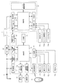
電源制御装置10の構成について説明する。図2に示すように、電源制御装置10は、制御部11と、記憶部12と、無線通信部13と、リレー駆動回路14と、ランプ駆動回路15aと、警音器駆動回路15bと、入力回路16と、電源回路17と、通信インターフェース部18と、残量検知回路19と、を有している。   The configuration of the power supply control device 10 will be described. As shown in FIG. 2, the power supply control device 10 includes a control unit 11, a storage unit 12, a wireless communication unit 13, a relay drive circuit 14, a lamp drive circuit 15 a, a sound alarm drive circuit 15 b, and an input. The circuit 16, the power supply circuit 17, the communication interface unit 18, and the remaining amount detection circuit 19 are included.

記憶部12はROMやRAMなどを備えており、制御部11によって実行されるプログラムを予め記憶している。制御部11は、マイクロプロセッサを含み、記憶部12に格納されたプログラムに従って動作する。例えば、制御部11は携帯機30を認証するための処理や、バッテリ41の電力が無駄に消費されるのを防止するために、所定の状況下では、ユーザーの操作を要することなく、バッテリ41の電力供給を停止する処理を行う。また、本実施形態では、制御部11は、バッテリ41の電力供給を停止し、オフ状態にする前に、電源スイッチ51のオフ操作をユーザーに促すための処理を実行する。制御部11が実行する処理については後において詳細に説明する。   The storage unit 12 includes a ROM, a RAM, and the like, and stores a program executed by the control unit 11 in advance. The control unit 11 includes a microprocessor and operates according to a program stored in the storage unit 12. For example, in order to prevent the processing for authenticating the portable device 30 and the power of the battery 41 from being wastedly consumed, the control unit 11 does not require user operation under a predetermined situation. To stop the power supply. Further, in the present embodiment, the control unit 11 performs a process for prompting the user to turn off the power switch 51 before stopping the power supply of the battery 41 and turning it off. The processing executed by the control unit 11 will be described in detail later.

無線通信部13は送信機や、受信機、無線アンテナ等を含み、制御部11から入力される信号を電波信号として送信する。また、無線通信部13は、携帯機30から受信した電波信号をデジタル信号として制御部11に出力する。なお、無線通信部13は予め設定された強度で電波を送信するよう設けられており、所定の通信範囲(例えば、電源制御装置10から数メートルの範囲)に携帯機30がある場合に、当該携帯機30との通信が可能となっている。   The wireless communication unit 13 includes a transmitter, a receiver, a wireless antenna, and the like, and transmits a signal input from the control unit 11 as a radio wave signal. Further, the wireless communication unit 13 outputs the radio signal received from the portable device 30 to the control unit 11 as a digital signal. Note that the wireless communication unit 13 is provided to transmit radio waves at a preset intensity, and when the portable device 30 is in a predetermined communication range (for example, a range of several meters from the power supply control device 10), Communication with the portable device 30 is possible.

リレー駆動回路14はリレー回路42に接続されており、制御部11から入力される信号に基づいてリレー回路42をオン状態又はオフ状態に設定する。   The relay drive circuit 14 is connected to the relay circuit 42 and sets the relay circuit 42 to an on state or an off state based on a signal input from the control unit 11.

入力回路16は電源スイッチ51と、複数の操作センサ52a,52b・・・52nとに接続されている。電源スイッチ51は、ユーザーがオン/オフ操作することによって、バッテリ41からECU20等の各種電装品への電力供給を許容又は停止するためのスイッチである。また、操作センサ52a,52b・・・52nは、例えば、左右のフラッシャ(不図示)を同時に点灯させるハザードスイッチや、左右のフラッシャのいずれか一方を点灯させる方向指示器スイッチや、シート6の開閉を検知するセンサである。電源スイッチ51と操作センサ52a,52b・・・52nは、それぞれユーザーの操作に応じて入力回路16に信号を出力し、入力回路16は当該信号を制御部11に入力する。   The input circuit 16 is connected to the power switch 51 and a plurality of operation sensors 52a, 52b,. The power switch 51 is a switch for allowing or stopping power supply from the battery 41 to various electrical components such as the ECU 20 when the user performs an on / off operation. The operation sensors 52a, 52b,... 52n are, for example, a hazard switch that lights both the left and right flashers (not shown), a direction indicator switch that lights one of the left and right flashers, and the opening and closing of the seat 6. It is a sensor which detects. The power switch 51 and the operation sensors 52a, 52b,... 52n each output a signal to the input circuit 16 according to a user operation, and the input circuit 16 inputs the signal to the control unit 11.

ランプ駆動回路15aは警告ランプ44に接続され、制御部11から入力される信号に従って警告ランプ44に電力を供給し、当該警告ランプ44を点灯させる。例えば、後述する制御部11の処理によって車両が停止してから長時間が経過したと認められた場合や、電源スイッチ51をオン状態にしたまま車両から立ち去ろうとしたために、携帯機30との通信が成立しなくなった場合に、ランプ駆動回路15aは制御部11の指示に従って警告ランプ44を点灯させる。警音器駆動回路15bは警音器45に接続され、制御部11から入力される信号に従って警告音45に電力を供給し、警音器45から警告音を発する。なお、警告ランプ44は、例えば車速を表示するスピードメータを含む表示装置44aに設けられる(図1参照)。   The lamp driving circuit 15 a is connected to the warning lamp 44, supplies power to the warning lamp 44 in accordance with a signal input from the control unit 11, and turns on the warning lamp 44. For example, when it is recognized that a long time has passed since the vehicle stopped due to the processing of the control unit 11 described later, or because the power switch 51 was left on, the communication with the portable device 30 was attempted. When this is not established, the lamp driving circuit 15a turns on the warning lamp 44 in accordance with an instruction from the control unit 11. The horn drive circuit 15b is connected to the horn 45, supplies power to the audible sound 45 according to a signal input from the control unit 11, and emits an audible alarm from the horn 45. The warning lamp 44 is provided in a display device 44a including a speedometer that displays the vehicle speed, for example (see FIG. 1).

電源回路17はバッテリ41に接続されており、当該バッテリ41から供給される電力を、電源制御装置10を構成する各部の動作電圧に変換して供給する。また、電源回路17は制御部11の指示に応じて、電源制御装置10を構成する各部への電力供給を停止する。   The power supply circuit 17 is connected to the battery 41, and converts the power supplied from the battery 41 into the operating voltage of each part constituting the power supply control device 10 and supplies it. Further, the power supply circuit 17 stops the power supply to each part constituting the power supply control device 10 in accordance with an instruction from the control unit 11.

通信インターフェース部18はECU20の通信インターフェース部26に接続されており、通信インターフェース部26が送信した信号を受信して制御部11に入力する。   The communication interface unit 18 is connected to the communication interface unit 26 of the ECU 20, receives a signal transmitted from the communication interface unit 26, and inputs the signal to the control unit 11.

残量検知回路19は、バッテリ41の残量を検知するための回路である。残量検知回路19はバッテリ41に接続されており、例えば、バッテリ41の出力電圧を示す信号を制御部11に入力し、制御部11は当該信号に基づいて、バッテリ41の残量を検知する。   The remaining amount detection circuit 19 is a circuit for detecting the remaining amount of the battery 41. The remaining amount detection circuit 19 is connected to the battery 41. For example, a signal indicating the output voltage of the battery 41 is input to the control unit 11, and the control unit 11 detects the remaining amount of the battery 41 based on the signal. .

ここで、電源制御装置10の制御部11とECU20の制御部21が実行する処理について説明する。図3は制御部21の機能ブロック図であり、図4は制御部11の機能ブロック図である。まず制御部21が実行する処理について説明する。図3に示すように、制御部21はその機能として停止判定部21aと使用判定部21bとを含んでいる。   Here, the process which the control part 11 of the power supply control apparatus 10 and the control part 21 of ECU20 perform is demonstrated. FIG. 3 is a functional block diagram of the control unit 21, and FIG. 4 is a functional block diagram of the control unit 11. First, processing executed by the control unit 21 will be described. As shown in FIG. 3, the control unit 21 includes a stop determination unit 21a and a use determination unit 21b as its functions.

停止判定部21aは車両が停止したか否かを判定する。具体的には、停止判定部21aは、車速センサ53aによって検知される車速と、エンジン回転数センサ53bによって検知されるエンジン回転数とに基づいて、車両が走行状態から停止状態に至ったか否かを判定する。例えば、停止判定部21aは、車速とエンジン回転数とが予め設定された条件(例えば、車速が所定の閾値(以下、車速閾値)より低く且つエンジン回転数が所定の閾値(以下回転数閾値)より低いこと(以下、停止判定条件))を充足する場合に、車両が停止したと判断する。なお、停止判定部21aは、このような停止判定条件を車両の運転状態が所定時間以上継続して充足する場合に、車両が停止したと判断してもよい。また、停止判定部21aは、スタンドセンサ53cによってスタンド7の使用状態を検知し、その使用状態に基づいて車両が停止状態にあるか否かを判定してもよい。例えば、車速が車速閾値より低く、且つ、スタンド7が使用されている場合に、停止判定部21aは、停止判定条件が満たされ、車両が停止状態にあると判断してもよい。   The stop determination unit 21a determines whether or not the vehicle has stopped. Specifically, stop determination unit 21a determines whether the vehicle has reached a stop state from the running state based on the vehicle speed detected by vehicle speed sensor 53a and the engine speed detected by engine speed sensor 53b. Determine. For example, the stop determination unit 21a has a condition in which the vehicle speed and the engine speed are set in advance (for example, the vehicle speed is lower than a predetermined threshold (hereinafter referred to as a vehicle speed threshold) and the engine speed is a predetermined threshold (hereinafter referred to as a rotational speed threshold). It is determined that the vehicle has stopped when the lower level (hereinafter referred to as stop determination condition) is satisfied. In addition, the stop determination part 21a may determine that the vehicle has stopped when the driving state of the vehicle continues to satisfy such a stop determination condition for a predetermined time or more. Moreover, the stop determination part 21a may detect the use state of the stand 7 by the stand sensor 53c, and may determine whether the vehicle is in a stop state based on the use state. For example, when the vehicle speed is lower than the vehicle speed threshold and the stand 7 is used, the stop determination unit 21a may determine that the stop determination condition is satisfied and the vehicle is in a stopped state.

使用判定部21bは、車両が停止状態にある場合に、ユーザーの操作に応じて信号を出力する各種センサ(例えば、スタンドセンサ53cや車速センサ53a)から入力される信号に基づいて、車両が使用されているか否かを判定する。例えば、使用判定部21bは、そのようなセンサからの信号が検知されない状態(すなわちユーザーによって車両の操作がなされていない状態)が、所定時間(以下、不使用判定時間)以上継続した場合に、車両が使用されていないと判断する。   When the vehicle is in a stopped state, the usage determining unit 21b uses the vehicle based on signals input from various sensors (for example, the stand sensor 53c and the vehicle speed sensor 53a) that output signals according to user operations. It is determined whether or not it has been done. For example, the use determination unit 21b is configured such that a state in which a signal from such a sensor is not detected (that is, a state in which the user has not operated the vehicle) continues for a predetermined time (hereinafter referred to as a non-use determination time) or longer. It is determined that the vehicle is not being used.

なお、使用判定部21bは、車両が使用されていないと判断すると、その旨を示す情報(以下、不使用通知情報)を電源制御装置10に送信する。また、使用判定部21bは、ECU20に接続された各種センサの信号に基づいて、ユーザーの車両操作を検知するとともに、ユーザーによって車両が使用されていることを示す情報(以下、使用通知情報)を電源制御装置10に送信する。電源制御装置10では、制御部11は、このようなECU20から送られる使用通知情報及び不使用通知情報に基づいて、車両の使用状態を検知する。   When the use determination unit 21b determines that the vehicle is not being used, the use determination unit 21b transmits information indicating the fact (hereinafter, non-use notification information) to the power supply control device 10. In addition, the use determination unit 21b detects the user's vehicle operation based on signals from various sensors connected to the ECU 20, and also indicates information indicating that the vehicle is being used by the user (hereinafter referred to as use notification information). It transmits to the power supply control apparatus 10. In the power supply control device 10, the control unit 11 detects the use state of the vehicle based on the use notification information and the non-use notification information sent from the ECU 20.

次に、制御部11が実行する処理について説明する。制御部11は、車両の停止状態においてバッテリ41の電力供給がオン状態にある場合に、警告ランプ44や警音器45等の警告器を作動せることによって、ユーザーに対して電源スイッチ51のオフ操作を促す。本実施形態では特に、制御部11は、車両の停止状態において携帯機30との通信が成功する状態が続く場合、すなわちユーザーが車両の近くにいると認められる場合に、このような警告器を作動させる。さらに携帯機30との通信が成功しなくなった場合には、携帯機30との通信が成功する場合とは異なる態様で、警告器を作動させる。以下、制御部11の処理について詳細に説明する。   Next, processing executed by the control unit 11 will be described. When the power supply of the battery 41 is in an on state when the vehicle is stopped, the control unit 11 activates a warning device such as a warning lamp 44 or a sound alarm 45 to turn off the power switch 51 to the user. Encourage operation. Particularly in the present embodiment, the control unit 11 displays such a warning device when the communication with the portable device 30 continues in a stopped state of the vehicle, that is, when it is recognized that the user is near the vehicle. Operate. Further, when communication with the portable device 30 is no longer successful, the warning device is activated in a manner different from that when the communication with the portable device 30 is successful. Hereinafter, the process of the control part 11 is demonstrated in detail.

図4に示すように、制御部11は、その機能として、停止判定部11aと、通信処理部11bと、警告処理部11cと、紛失検知処理部11fとを含んでいる。また、警告処理部11cは成立時処理部11dと不成立時処理部11eとを含んでいる。   As shown in FIG. 4, the control unit 11 includes a stop determination unit 11a, a communication processing unit 11b, a warning processing unit 11c, and a loss detection processing unit 11f as its functions. In addition, the warning processing unit 11c includes an established time processing unit 11d and a non-established time processing unit 11e.

停止判定部11aは車両が停止したか否かを判定する。この説明では、電源制御装置10には、車速とエンジン回転数とがECU20から通知されており、停止判定部11aは、通知された車速とエンジン回転数とに基づいて、車両が停止したか否かを判定する。例えば、上述した停止判定部21aと同様に、車速とエンジン回転数とが停止判定条件に該当するか否かを判定する。なお、停止判定部11aは、このような停止判定条件を車両の運転状態が所定時間以上継続して充足する場合に、車両が停止したと判断してもよい。   The stop determination unit 11a determines whether or not the vehicle has stopped. In this description, the power supply control device 10 is notified of the vehicle speed and the engine speed from the ECU 20, and the stop determination unit 11a determines whether the vehicle has stopped based on the notified vehicle speed and the engine speed. Determine whether. For example, similarly to the stop determination unit 21a described above, it is determined whether the vehicle speed and the engine speed meet the stop determination condition. In addition, the stop determination part 11a may determine that the vehicle has stopped when the driving state of the vehicle continuously satisfies such a stop determination condition for a predetermined time or more.

また、電源制御装置10には車速及びエンジン回転数に代えて、ECU20の停止判定部21aの処理の結果、すなわち車両が停止状態にある場合にはその旨が通知されてもよい。また、制御部11にはECU20からスタンド7の使用状態が通知されてもよい。この場合、停止判定部11eは、スタンド7の使用状態に基づいて車両が停止しているか否かを判定してもよい。   Further, instead of the vehicle speed and the engine speed, the power supply control device 10 may be notified of the result of the process of the stop determination unit 21a of the ECU 20, that is, if the vehicle is in a stopped state. Further, the use state of the stand 7 may be notified from the ECU 20 to the control unit 11. In this case, the stop determination unit 11e may determine whether or not the vehicle is stopped based on the usage state of the stand 7.

通信処理部11bは、車両の停止状態において携帯機30との通信を試行し、当該通信が成功するか否かを判定する。具体的には、通信処理部11bは、携帯機30に応答を要求する応答要求信号を、所定の時間間隔で送信する。そして、当該応答要求信号に対する信号を携帯機30から受信しない場合に、通信処理部11bは、携帯機30との通信が成立しないと判断する。なお、通信処理部11bは、複数回、応答要求信号を送信することで、携帯機30との通信を試行してもよい。この場合、通信処理部11bは、いずれの応答要求信号に対しても携帯機30の応答が無い場合に、携帯機30との通信が成立しないと判断する。   The communication processing unit 11b tries to communicate with the portable device 30 in a stopped state of the vehicle, and determines whether or not the communication is successful. Specifically, the communication processing unit 11b transmits a response request signal requesting a response to the portable device 30 at a predetermined time interval. When the signal for the response request signal is not received from the portable device 30, the communication processing unit 11 b determines that communication with the portable device 30 is not established. Note that the communication processing unit 11b may try to communicate with the portable device 30 by transmitting a response request signal a plurality of times. In this case, the communication processing unit 11b determines that communication with the portable device 30 is not established when there is no response from the portable device 30 to any response request signal.

警告処理部11cは、車両の停止状態において未だ電源スイッチ51がオン状態にある時に、警告ランプ44を点灯させて、ユーザーに対して電源スイッチ51のオフ操作を促す。詳細には、警告処理部11cが含む成立時処理部11dは、車両の停止状態においてバッテリ41の電力供給がオン状態にあり、且つ、携帯機30との通信が成功する場合に、予め設定された態様(以下、成立時警告態様)で警告ランプ44を点灯させる。なお、成立時処理部11dは警告ランプ44に代えて、警音器45を作動させて警告音を鳴らしてもよい。   The warning processing unit 11c turns on the warning lamp 44 when the power switch 51 is still in the on state when the vehicle is stopped, and prompts the user to turn off the power switch 51. Specifically, the establishment processing unit 11d included in the warning processing unit 11c is set in advance when the power supply of the battery 41 is in an on state when the vehicle is stopped and communication with the portable device 30 is successful. The warning lamp 44 is turned on in the above mode (hereinafter referred to as a warning mode when established). The establishment processing unit 11d may sound a warning sound by operating the alarm 45 instead of the warning lamp 44.

また、成立時処理部11dは、車両が停止してからの経過時間(以下、停止経過時間)が、所定時間(以下、警告条件時間)に達したか否かを判定し、停止経過時間が警告条件時間に達した後に、警告ランプ44を点灯させてもよい。すなわち、成立時処理部11dは、車両の停止状態が警告条件時間を越えて続いている場合に、警告ランプ44を点灯させてもよい。   Further, the establishment processing unit 11d determines whether or not an elapsed time since the vehicle stopped (hereinafter referred to as an elapsed stop time) has reached a predetermined time (hereinafter referred to as a warning condition time). After reaching the warning condition time, the warning lamp 44 may be turned on. That is, the establishment processing unit 11d may turn on the warning lamp 44 when the stop state of the vehicle continues beyond the warning condition time.

また、成立時処理部11dは、警告条件時間をバッテリ41や、当該バッテリ41から電力が供給される電装品の使用状態に基づいて設定してもよい。例えば、成立時処理部11dは、残量検知回路19によって検知されるバッテリ41の残量に基づいて、警告条件時間を設定してもよい。この処理では、例えば、残量検知回路19によって検知されるバッテリ41の残量が予め設定された値(以下、残量閾値)を下回った場合には、成立時処理部11dは、当該残量が残量閾値を上回っている場合に比べて、警告条件時間を短縮してもよい。   Further, the establishment processing unit 11d may set the warning condition time based on the usage state of the battery 41 or an electrical component to which power is supplied from the battery 41. For example, the establishment processing unit 11d may set the warning condition time based on the remaining amount of the battery 41 detected by the remaining amount detection circuit 19. In this process, for example, when the remaining amount of the battery 41 detected by the remaining amount detection circuit 19 falls below a preset value (hereinafter referred to as remaining amount threshold), the establishment processing unit 11d The warning condition time may be shortened as compared with the case where is higher than the remaining amount threshold.

また、成立時処理部11dは、ユーザーによって車両が使用されている場合には、警告ランプ44の点灯を制限してもよい。この処理は、例えば、次のようにして実行される。ここで説明する例では、上述したようにユーザーによって車両が使用されていない場合には、電源制御装置10にECU20から不使用通知情報が送信されている。そこで、成立時処理部11dは、警告ランプ44の作動を開始する前に、不使用通知情報を受信しているか否かを判定し、未だ受信していない場合には、当該不使用通知情報を受信するまで、警告ランプ44の点灯を待機する。   Further, the establishment processing unit 11d may limit the lighting of the warning lamp 44 when the vehicle is used by the user. This process is executed as follows, for example. In the example described here, non-use notification information is transmitted from the ECU 20 to the power supply control device 10 when the vehicle is not used by the user as described above. Therefore, the establishment processing unit 11d determines whether or not the non-use notification information has been received before starting the operation of the warning lamp 44. If the non-use notification information has not been received yet, the non-use notification information is displayed. It waits for lighting of the warning lamp 44 until it receives.

また、成立時処理部11dは、電源制御装置10に接続されている操作センサ52a,52b・・52n等から入力される信号の有無に基づいて、警告ランプ44を点灯させるか否かを判定してもよい。例えば、成立時処理部11dは、これらの操作センサ52a,52b・・52n等から、ユーザーの操作を示す信号が入力された場合には、そのような信号の入力が無い状態が所定時間以上継続するまで警告ランプ44の点灯を待機してもよい。   Further, the establishment processing unit 11d determines whether to turn on the warning lamp 44 based on the presence / absence of a signal input from the operation sensors 52a, 52b,... 52n connected to the power supply control device 10. May be. For example, when a signal indicating a user's operation is input from the operation sensors 52a, 52b,... 52n, etc., the establishment processing unit 11d continues for a predetermined time or longer without such a signal input. You may wait for lighting of the warning lamp 44 until it does.

また、成立時処理部11dは、車両が使用されておらず、且つ、携帯機30との通信が成立する状態が、所定時間(例えば、上述の警告条件時間)以上継続する場合に警告ランプ44を作動させてもよい。こうすることによって、ユーザーが車両の近くにいるにも拘らず車両が使用されていない状況で、警告ランプ44を作動させることができ、より効果的に電源スイッチ51のオフ操作をユーザーに対して促すことができる。   In addition, the establishment processing unit 11d is configured to issue a warning lamp 44 when the vehicle is not used and communication with the portable device 30 is established for a predetermined time (for example, the above-described warning condition time) or longer. May be activated. In this way, the warning lamp 44 can be activated in a situation where the vehicle is not being used even though the user is near the vehicle, and the power switch 51 can be turned off more effectively to the user. Can be urged.

この処理は、例えば、次のようにして実行される。成立時処理部11dは、車両が停止状態に至ってからの経過時間、すなわち停止経過時間を計測する間に、ECU20から車両が使用されていることを示す使用通知情報を受信した場合、或いは通信処理部11bによる携帯機30との通信が成功しなくなった場合には、それまで計測していた停止経過時間をリセットし、再度計測を開始する。こうすることによって、車両が使用されていないこと、及び、携帯機30との通信が成立することの双方が、所定時間以上継続すること場合に、警告ランプ44を作動させることが出来る。なお、この処理では、成立時処理部11dは、ECU20から送信される不使用通知情報及び使用通知情報に基づいて、ユーザーによる車両の使用状態を検知する。   This process is executed as follows, for example. The establishment processing unit 11d receives use notification information indicating that the vehicle is being used from the ECU 20 while measuring the elapsed time since the vehicle reached the stop state, that is, the stop elapsed time, or communication processing. When the communication with the portable device 30 by the unit 11b does not succeed, the elapsed stop time that has been measured until then is reset, and the measurement is started again. By doing so, the warning lamp 44 can be activated when both the vehicle is not being used and the establishment of communication with the portable device 30 continues for a predetermined time or longer. In this process, the establishment processing unit 11d detects the use state of the vehicle by the user based on the non-use notification information and the use notification information transmitted from the ECU 20.

また、成立時処理部11dは、車両が停止する前の走行状態において携帯機30が紛失されている場合には、この様な警告ランプ44による警告を制限してもよい。すなわち、後述する紛失判定部11dの処理において走行中に携帯機30の紛失が検知されている場合には、成立時処理部11dは警告ランプ44の点灯が制限されてもよい。   Further, the establishment processing unit 11d may limit such warning by the warning lamp 44 when the portable device 30 is lost in the traveling state before the vehicle stops. That is, when the loss of the portable device 30 is detected during traveling in the process of the loss determination unit 11d described later, the establishment processing unit 11d may be restricted from lighting the warning lamp 44.

また、成立時処理部11dは、警告ランプ44を点灯させて、ユーザーによる電源スイッチ51のオフ操作を促した後においても、電源スイッチ51のオン状態が維持される場合には、バッテリ41の電力供給を停止する処理を実行してもよい。この場合、成立時処理部11dは、例えば、上述した警告条件時間より長く設定された時間(以下、第1自動停止条件時間)に、停止経過時間が達した時に、バッテリ41の電力供給を停止する処理(以下、自動停止処理)を実行してもよい。この自動停止処理では、リレー回路42をオフ状態に設定してECU20への電力供給を停止するとともに、電源回路17から電源制御装置10を構成する各部への電力供給を停止或いは低減させて、電源制御装置10を待機状態に移行させる。   Further, when the establishment processing unit 11d turns on the warning lamp 44 and prompts the user to turn off the power switch 51, the power of the battery 41 is maintained. You may perform the process which stops supply. In this case, the establishment processing unit 11d stops the power supply of the battery 41 when, for example, the stop elapsed time has reached a time set longer than the above-described warning condition time (hereinafter referred to as a first automatic stop condition time). Processing (hereinafter referred to as automatic stop processing) may be executed. In this automatic stop process, the relay circuit 42 is set to an off state to stop the power supply to the ECU 20, and the power supply from the power supply circuit 17 to each part of the power supply control device 10 is stopped or reduced to The control device 10 is shifted to the standby state.

上述したように、警告処理部11cは不成立時処理部11eを含んでいる。不成立時処理部11eは、車両の停止状態において、通信処理部11bによる携帯機30との通信が成功しない場合に、上述した成立時警告態様とは異なる態様で(以下、不成立時警告態様)で、警告ランプ44を点灯させる。例えば、成立時警告態様おいて警告ランプ44を点滅させている場合には、不成立時警告態様では、その点滅の頻度を高くしたり、輝度を高くする。   As described above, the warning processing unit 11c includes the failure processing unit 11e. The non-establishment processing unit 11e is different from the above-described establishment-time warning mode (hereinafter referred to as non-establishment warning mode) when communication with the portable device 30 by the communication processing unit 11b is not successful when the vehicle is stopped. The warning lamp 44 is turned on. For example, when the warning lamp 44 is blinking in the establishment warning mode, in the non-establishment warning mode, the frequency of the blinking is increased or the luminance is increased.

また、不成立時処理部11eとは、成立時処理部11dの処理とは異なり、車両の停止状態において携帯機30との通信が成功しない場合には、直ちに警告ランプ44を点灯させてもよい。   Further, unlike the processing of the establishment processing unit 11d, the failure processing unit 11e may immediately turn on the warning lamp 44 when the communication with the portable device 30 is not successful in the vehicle stop state.

また、不成立時処理部11eは、携帯機30との通信が成功しない状態で警告ランプ44を点灯させた後においても、バッテリ41の電力供給のオン状態が継続する場合には、バッテリ41の電力供給を自動で停止してもよい。例えば、不成立時処理部11eは、車両が停止している状態で、携帯機30との通信が成立しなくなってからの経過時間(以下、不成立経過時間)を計数する。そして、不成立時処理部11eは、当該不成立経過時間が予め設定された時間(以下、第2自動停止条件時間)に達した場合に、バッテリ41による電力供給を停止してもよい。   In addition, the non-established time processing unit 11e, if the power supply of the battery 41 continues to be on even after the warning lamp 44 is turned on in a state where the communication with the portable device 30 is not successful, The supply may be automatically stopped. For example, the non-establishment processing unit 11e counts elapsed time (hereinafter, non-established elapsed time) after communication with the portable device 30 is not established in a state where the vehicle is stopped. The failure processing unit 11e may stop the power supply by the battery 41 when the failure establishment elapsed time reaches a preset time (hereinafter referred to as a second automatic stop condition time).

紛失検知処理部11fは、車両の走行中における携帯機30の紛失を検知するための処理を実行する。具体的には、紛失検知処理部11fは、車両が走行状態にある時に、携帯機30に応答を要求する応答要求信号を間欠的に送信して、携帯機30との通信を試行する。そして、携帯機30の応答を受信せず、携帯機30との通信が成功しない場合に、紛失検知処理部11fは携帯機30の紛失が生じたものと判断する。なお、紛失検知処理部11fによって携帯機30の紛失が検知された場合には、上述した成立時処理部11dや不成立時処理部11eによる警告ランプ44の作動は制限されてもよい。   The loss detection processing unit 11f executes processing for detecting loss of the portable device 30 while the vehicle is traveling. Specifically, the loss detection processing unit 11 f intermittently transmits a response request signal requesting a response to the portable device 30 when the vehicle is in a traveling state, and tries communication with the portable device 30. If the response from the portable device 30 is not received and the communication with the portable device 30 is not successful, the loss detection processing unit 11f determines that the loss of the portable device 30 has occurred. When the loss detection processing unit 11f detects the loss of the portable device 30, the operation of the warning lamp 44 by the establishment processing unit 11d or the non-establishment processing unit 11e described above may be limited.

ここで、制御部11が実行する処理の流れについて説明する。図5は制御部11が実行する処理の例を示すフローチャートである。なお、この説明では、上述した停止経過時間を計測するための停止経過変数i1が、制御部11の処理において順次インクリメントされ、当該停止経過変数i1が、警告条件時間に対応する値(以下、警告条件値kw)に達した場合に警告ランプ44による警告が開始される。その後停止経過変数i1が、さらに第1自動停止条件時間に対応する値(以下、第1自動停止条件値ks1)に達した場合に、バッテリ41の電力供給を停止する処理を行う。また、上述した不成立経過時間を計測するための不成立経過変数i2が制御部11の処理において順次インクリメントされ、当該不成立経過変数i2が、第2自動停止条件時間に対応する値(以下、第2自動停止条件値ks2)に達した場合に自動でバッテリ41の電力供給を停止する処理を行う。   Here, the flow of processing executed by the control unit 11 will be described. FIG. 5 is a flowchart illustrating an example of processing executed by the control unit 11. In this description, the stop progress variable i1 for measuring the stop elapsed time described above is sequentially incremented in the processing of the control unit 11, and the stop progress variable i1 is a value corresponding to the warning condition time (hereinafter, warning). When the condition value kw) is reached, a warning by the warning lamp 44 is started. Thereafter, when the stop progress variable i1 further reaches a value corresponding to the first automatic stop condition time (hereinafter referred to as a first automatic stop condition value ks1), a process of stopping the power supply of the battery 41 is performed. Further, the above-described failure success variable i2 for measuring the failure failure elapsed time is sequentially incremented in the processing of the control unit 11, and the failure failure variable i2 is a value corresponding to the second automatic stop condition time (hereinafter referred to as a second automatic stop condition time). When the stop condition value ks2) is reached, a process of automatically stopping the power supply of the battery 41 is performed.

まず、警告処理部11cは、停止経過変数i1と不成立経過変数i2とを初期値0に設定する(S101)。また、停止判定部11aは、ECU20から通知される車速とエンジン回転数とに基づいて、車両が走行状態から停止状態に至ったか否かを判定する(S102)。ここで車両が未だ走行状態にある場合には、紛失処理部11fが携帯機30の紛失を検知するための処理を行った後(S116)、制御部11の処理はS101に戻る。   First, the warning processing unit 11c sets the stop progress variable i1 and the failure progress variable i2 to the initial value 0 (S101). Moreover, the stop determination part 11a determines whether the vehicle has reached the stop state from the running state based on the vehicle speed and the engine speed notified from the ECU 20 (S102). If the vehicle is still running, the loss processing unit 11f performs processing for detecting the loss of the portable device 30 (S116), and then the processing of the control unit 11 returns to S101.

一方、S102で車両が停止状態に至ったと判断された場合には、制御部11は、ユーザーによって電源スイッチ51がオフされたか否かを判定する(S103)。ここで、電源スイッチ51がオフされている場合には、制御部11は、バッテリ41の電力供給を停止する処理を実行する(S104)。具体的には、制御部11は、リレー回路42をオフ状態に設定してECU20への電力供給を停止するとともに、電源回路17を制御して、電源制御装置10を待機状態に移行させる。なお、この時、制御部11は、S116の処理において携帯機30の紛失が検知されているか否かを判定し、携帯機30の紛失が生じている場合には、バッテリ41の電力供給を停止する前に警告ランプ44を作動させてもよい。   On the other hand, when it is determined in S102 that the vehicle has come to a stop state, the control unit 11 determines whether or not the power switch 51 is turned off by the user (S103). Here, when the power switch 51 is turned off, the control unit 11 executes a process of stopping the power supply of the battery 41 (S104). Specifically, the control unit 11 sets the relay circuit 42 in the off state to stop the power supply to the ECU 20 and controls the power supply circuit 17 to shift the power supply control device 10 to the standby state. At this time, the control unit 11 determines whether the loss of the portable device 30 is detected in the process of S116, and stops the power supply of the battery 41 when the loss of the portable device 30 occurs. The warning lamp 44 may be actuated before starting.

S103の処理で、電源スイッチ51が未だオフされていない場合には、成立時処理部11dは、ECU20から送信された不使用通知情報又は使用通知情報に基づいて、ユーザーによって車両が使用されているか否かを判定する(S105)。ここで、ユーザーによって車両が使用されている場合には、制御部11の処理はS101に戻り、再び以降の処理を実行する。一方、S105で車両が使用されていないと判断された場合には、警告処理部11cは残量検知回路19から入力される信号に基づいて、バッテリ残量を検知し、当該バッテリ残量に基づいて、警告条件値kw、第1自動停止条件値ks1、及び第2自動停止条件値ks2をそれぞれ設定する(S106)。その後、通信処理部11bは、携帯機30との通信を複数回試行し、携帯機30との通信が成功するか否かを判定する(S107)。ここで、携帯機30との通信が成功する場合には、成立時処理部11dは、停止経過変数i1が警告条件値kwを超えているか否かを判定する(S108)。未だ停止経過変数i1が警告条件値kwを超えていない場合には、成立時処理部11dは、停止経過変数i1をインクリメントした後(S109)、S102の処理に戻り、以降の処理を実行する。なお、このように、制御部11の処理がS102に戻ることによって、車両の停止状態と、車両が使用されていない状態と、携帯機30との通信が成功する状態のいずれもが、所定時間以上継続する場合に、警告ランプ44が点灯するようになる。   In the process of S103, if the power switch 51 is not yet turned off, the establishment processing unit 11d determines whether the vehicle is being used by the user based on the non-use notification information or the use notification information transmitted from the ECU 20. It is determined whether or not (S105). Here, when the vehicle is being used by the user, the process of the control unit 11 returns to S101, and the subsequent processes are executed again. On the other hand, when it is determined in S105 that the vehicle is not being used, the warning processing unit 11c detects the remaining battery level based on the signal input from the remaining battery level detection circuit 19, and based on the remaining battery level. Then, a warning condition value kw, a first automatic stop condition value ks1, and a second automatic stop condition value ks2 are set (S106). Thereafter, the communication processing unit 11b tries communication with the portable device 30 a plurality of times, and determines whether or not the communication with the portable device 30 is successful (S107). Here, when the communication with the portable device 30 is successful, the establishment processing unit 11d determines whether or not the stop progress variable i1 exceeds the warning condition value kw (S108). When the stop progress variable i1 has not yet exceeded the warning condition value kw, the establishment processing unit 11d increments the stop progress variable i1 (S109), returns to the process of S102, and executes the subsequent processes. As described above, when the process of the control unit 11 returns to S102, the vehicle stop state, the vehicle is not being used, and the state in which communication with the portable device 30 is successful are performed for a predetermined time. When the operation is continued, the warning lamp 44 is turned on.

S108において、停止経過変数i1が警告条件値kwを超えている場合には、成立時処理部11dは、上述した成立時警告態様にて警告ランプ44を点灯させる(S110)。その後、成立時処理部11dは、停止経過変数i1が第1自動停止条件値ks1を超えているか否かを判定する(S111)。未だ停止経過変数i1が第1自動停止条件値ks1を超えていない場合には、成立時処理部11dは、停止経過変数i1をインクリメントした後(S109)、S102の処理に戻る。また、S111で停止経過変数i1が第1自動停止条件値ks1を超えている場合には、警告処理部11cはバッテリ41の電力供給を停止する処理を実行する(S112)。   In S108, when the stop progress variable i1 exceeds the warning condition value kw, the establishment processing unit 11d turns on the warning lamp 44 in the establishment warning manner described above (S110). Thereafter, the establishment processing unit 11d determines whether or not the stop progress variable i1 exceeds the first automatic stop condition value ks1 (S111). If the stop progress variable i1 has not yet exceeded the first automatic stop condition value ks1, the establishment processing unit 11d increments the stop progress variable i1 (S109), and then returns to the process of S102. On the other hand, if the stop progress variable i1 exceeds the first automatic stop condition value ks1 in S111, the warning processing unit 11c executes a process of stopping the power supply of the battery 41 (S112).

また、S107の処理で携帯機30との通信が成立しない場合には、不成立時処理部11eは直ちに不成立時警告態様にて警告ランプ44を点灯させる(S113)。その後、不成立時処理部11eは不成立経過変数i2が第2自動停止条件値ks2に達しているか否かを判定する(S114)。未だ不成立経過変数i2が第2自動停止条件値ks2に達していない場合には、不成立時処理部11eが不成立経過変数i2をインクリメントするとともに、成立時処理部11dが停止経過変数i1を初期値0に設定した後(S115)、制御部11の処理はS102に戻る。なお、このように、停止経過変数i1が初期値0に設定されることによって、携帯機30との通信が成否を繰り返す場合に、警告ランプ44による警告が間欠的に実施されるようになる。S114で既に不成立経過変数i2が第2自動停止条件値ks2に達している場合には、警告処理部11cはバッテリ41の電力供給を停止する処理を実行する(S112)。   If communication with the portable device 30 is not established in the process of S107, the failure processing unit 11e immediately turns on the warning lamp 44 in a failure warning mode (S113). Thereafter, the failure processing unit 11e determines whether or not the failure establishment variable i2 has reached the second automatic stop condition value ks2 (S114). If the failure condition variable i2 has not yet reached the second automatic stop condition value ks2, the failure condition processing unit 11e increments the failure condition variable i2, and the response processing unit 11d sets the stop progress variable i1 to the initial value 0. (S115), the control unit 11 returns to S102. As described above, when the stop progress variable i1 is set to the initial value 0, when the communication with the portable device 30 repeats success or failure, the warning by the warning lamp 44 is intermittently performed. When the failure condition variable i2 has already reached the second automatic stop condition value ks2 in S114, the warning processing unit 11c executes a process of stopping the power supply of the battery 41 (S112).

以上説明した車両制御装置1では、警告処理部11cに含まれる成立時処理部11dは、車両の停止状態においてバッテリ41の電力供給がオン状態にある場合であって、携帯機30との通信が成功する場合に、警告ランプ44又は警音器45を作動させている。これによって、ユーザーが車両の近くにいる場合においても、バッテリ41の電力供給の停止をユーザーに促すことができので、無駄な電力消費をより効果的に抑えることができる。   In the vehicle control device 1 described above, the establishment processing unit 11d included in the warning processing unit 11c is a case where the power supply of the battery 41 is in an on state when the vehicle is stopped, and communication with the portable device 30 is performed. If successful, the warning lamp 44 or horn 45 is activated. Accordingly, even when the user is near the vehicle, the user can be urged to stop the power supply of the battery 41, so that wasteful power consumption can be more effectively suppressed.

また、警告処理部11cに含まれる不成立時処理部11eは、車両の停止状態において携帯機30との通信が成功しない場合には、携帯機30との通信が成功する場合とは異なる態様で警告ランプ44を点灯させている。これによって、ユーザーが電源スイッチ51のオフ操作をすることなく車両から立ち去ることを抑えることができる。また、警告ランプ44を点灯の態様が異なるので、例えば、緊急度に応じた警告を行うことが出来る。   Further, the failure processing unit 11e included in the warning processing unit 11c warns in a manner different from the case where the communication with the portable device 30 is successful when the communication with the portable device 30 is not successful when the vehicle is stopped. The lamp 44 is turned on. As a result, the user can be prevented from leaving the vehicle without turning off the power switch 51. Further, since the manner of lighting the warning lamp 44 is different, for example, a warning according to the degree of urgency can be given.

また、警告処理部11cに含まれる成立時処理部11dは、停止判定部11aによって車両が停止したと判断されてからの経過時間(以上の説明では停止経過時間)が所定時間(以上の説明では警告条件時間)に達したか否かを判定し、停止経過時間が警告条件時間に達した後に、警告ランプ44を点灯させている。これによって、より適切なタイミングでユーザーに対して電源スイッチ51のオフ操作を促すことができる。例えば、短時間だけ車両が停止した場合には、警告器の作動を抑えることが出来る。   In addition, the establishment processing unit 11d included in the warning processing unit 11c has a predetermined time (in the above description, the elapsed time since the stop determination unit 11a determines that the vehicle has been stopped). The warning lamp 44 is turned on after the stop elapsed time reaches the warning condition time. This can prompt the user to turn off the power switch 51 at a more appropriate timing. For example, when the vehicle stops for a short time, the operation of the warning device can be suppressed.

また、車両制御装置1では、バッテリ41の残量を検知するための残量検知回路19が設けられ、警告処理部11cの成立時処理部11dは、バッテリ残量に基づいて警告条件時間を設定している。これによって、バッテリ残量が低い場合には、バッテリ残量が高い場合に比べて、早いタイミングで警告器を作動させることができる。   Further, the vehicle control device 1 is provided with a remaining amount detection circuit 19 for detecting the remaining amount of the battery 41, and the processing unit 11d when the warning processing unit 11c is established sets the warning condition time based on the remaining battery level. is doing. As a result, when the remaining battery level is low, the warning device can be operated at an earlier timing than when the remaining battery level is high.

また、自動二輪車100には、ユーザーによる車両の操作に応じて信号を出力するセンサ(例えば、スタンドスイッチ53c)が設けられ、車両制御装置1には、センサから入力される信号に基づいてユーザーが車両を使用しているか否かを判定する使用判定部21bが設けられている。そして、成立時処理部11dは、車両が使用されている場合には警告ランプ44や警音器45の作動を制限している。   In addition, the motorcycle 100 is provided with a sensor (for example, a stand switch 53c) that outputs a signal in accordance with the operation of the vehicle by the user, and the vehicle control device 1 has a user input based on a signal input from the sensor. A use determination unit 21b that determines whether or not the vehicle is used is provided. Then, the establishment processing unit 11d restricts the operation of the warning lamp 44 and the audible alarm 45 when the vehicle is used.

これによって、ユーザーが車両を使用していない場合に警告ランプ44等の警告器を作動させることができ、より適切なタイミングで警告を行うことが出来る。例えば、ユーザーが車両を使用することなく、他の作業を行なっている場合に、警告器を作動させることができる。   As a result, when the user is not using the vehicle, a warning device such as the warning lamp 44 can be operated, and a warning can be given at a more appropriate timing. For example, the warning device can be activated when the user is performing other work without using the vehicle.

なお、本発明は以上説明した車両制御装置1に限られず種々の変更が可能である。例えば、以上の説明では、警告器として警告ランプ44及び警音器45を例にしたが、警告器はこれに限られず、例えば、フラッシャやヘッドライト等の灯火器を警告器として用いてもよい。   The present invention is not limited to the vehicle control device 1 described above, and various modifications can be made. For example, in the above description, the warning lamp 44 and the audible alarm 45 are taken as an example of the warning device, but the warning device is not limited to this, and a lighting device such as a flasher or a headlight may be used as the warning device. .

また、以上の説明では、車両制御装置1は、電源制御装置10とECU20とを含み、電源制御装置10は、ECU20から車速やエンジン回転数、使用通知情報、不使用通知情報等が通知されていた。しかしながら、電源制御装置10が直接車速センサ53aやエンジン回転数センサ53b、スタンドスイッチ53c等に接続されてもよい。そして、電源制御装置10が、車速やエンジン回転数に基づいて車両が停止したか否かを判定するとともに、ユーザーによって車両が使用されているか否かを判定する処理を実行してもよい。   In the above description, the vehicle control device 1 includes the power supply control device 10 and the ECU 20, and the power supply control device 10 is notified of the vehicle speed, the engine speed, the usage notification information, the non-use notification information, and the like from the ECU 20. It was. However, the power supply control device 10 may be directly connected to the vehicle speed sensor 53a, the engine speed sensor 53b, the stand switch 53c, and the like. Then, the power supply control device 10 may determine whether or not the vehicle has stopped based on the vehicle speed and the engine speed, and may execute a process for determining whether or not the vehicle is being used by the user.

本発明の一実施形態に係る車両制御装置を備えた自動二輪車の概略の側面図である。1 is a schematic side view of a motorcycle including a vehicle control device according to an embodiment of the present invention. 上記自動二輪車が備える装置のブロック図である。It is a block diagram of an apparatus with which the motorcycle is provided. 上記車両制御装置が備えるECUの制御部の機能ブロック図である。It is a functional block diagram of the control part of ECU with which the said vehicle control apparatus is provided. 上記車両制御装置が備える電源制御装置の制御部の機能ブロック図である。It is a functional block diagram of the control part of the power supply control apparatus with which the said vehicle control apparatus is provided. 上記電源制御装置の制御が実行する処理の例のフローチャートである。It is a flowchart of the example of the process which control of the said power supply control apparatus performs.

符号の説明Explanation of symbols

1 車両制御装置、2 エンジン、3 前輪、4 後輪、5 ハンドル、6 シート、7 サイドスタンド、8 フロントフォーク、9 伝達ユニット、10 電源制御装置、11 制御部、11a 停止判定部、11b 通信処理部、11c 警告処理部、11d 成立時処理部、11e 不成立時処理部、11f 紛失検知処理部、12 記憶部、13 無線通信部、14 リレー駆動回路、15 ランプ駆動回路、16 入力回路、17 電源回路、18 通信インターフェース部、19 残量検知回路(検知部)、20 ECU、21 制御部、21a 停止判定部、21b 使用判定部、22 記憶部、23 電源回路、24 エンジン駆動回路、25 入力回路、26 通信インターフェース部、30 携帯機、41 バッテリ(電源)、42 リレー回路、44 警告ランプ(警告器)、45 警音器(警告器)、51 電源スイッチ、52a,52b,52n 操作センサ、100 自動二輪車。   DESCRIPTION OF SYMBOLS 1 Vehicle control apparatus, 2 Engine, 3 Front wheel, 4 Rear wheel, 5 Handle, 6 Seat, 7 Side stand, 8 Front fork, 9 Transmission unit, 10 Power supply control apparatus, 11 Control part, 11a Stop determination part, 11b Communication processing part , 11c Warning processing unit, 11d Processing unit when established, 11e Processing unit when not established, 11f Loss detection processing unit, 12 Storage unit, 13 Wireless communication unit, 14 Relay drive circuit, 15 Lamp drive circuit, 16 Input circuit, 17 Power supply circuit , 18 communication interface unit, 19 remaining amount detection circuit (detection unit), 20 ECU, 21 control unit, 21a stop determination unit, 21b use determination unit, 22 storage unit, 23 power supply circuit, 24 engine drive circuit, 25 input circuit, 26 Communication interface unit, 30 Mobile device, 41 Battery (power supply), 42 Relay times , 44 warning lamp (warning device) 45 horn (warning unit), 51 a power switch, 52a, 52 b, 52n operation sensor, 100 motorcycle.

Claims (8)

電装品へ電力を供給する電源とともに車両に搭載され、ユーザーによって所持される携帯機と通信可能に設けられる車両制御装置であって、
車両が停止しているか否かを判定する停止判定部と、
前記携帯機との通信を試行する通信処理部と、
車両の停止状態において前記電源の電力供給がオン状態にある場合であって、前記通信処理部による前記携帯機との通信が成功する場合に、車両に設けられた警告器を作動させる警告処理部と、
を備えることを特徴とする車両制御装置。
A vehicle control device that is mounted on a vehicle together with a power source for supplying electric power to an electrical component and is provided so as to be able to communicate with a portable device possessed by a user,
A stop determination unit that determines whether or not the vehicle is stopped;
A communication processing unit for attempting communication with the portable device;
A warning processing unit that activates a warning device provided in the vehicle when the power supply of the power source is in an on state when the vehicle is stopped and the communication processing unit communicates with the portable device. When,
A vehicle control device comprising:
請求項1に記載の車両制御装置において、
前記警告処理部は、車両の停止状態において前記通信部による前記携帯機との通信が成功しない場合には、前記携帯機との通信が成功する場合とは異なる態様で前記警告器を作動させる、
ことを特徴とする車両制御装置。
The vehicle control device according to claim 1,
If the communication with the portable device by the communication unit is not successful when the vehicle is stopped, the warning processing unit operates the warning device in a mode different from the case where the communication with the portable device is successful.
The vehicle control apparatus characterized by the above-mentioned.
請求項1に記載の車両制御装置において、
前記警告処理部は、前記停止判定部によって車両が停止したと判断されてからの経過時間が所定時間に達したか否かを判定し、前記経過時間が前記所定時間に達した後に、前記警告器を作動させる、
ことを特徴とする車両制御装置。
The vehicle control device according to claim 1,
The warning processing unit determines whether an elapsed time after the stop determination unit determines that the vehicle has stopped has reached a predetermined time, and after the elapsed time has reached the predetermined time, the warning processing unit Actuate the vessel,
The vehicle control apparatus characterized by the above-mentioned.
請求項3に記載の車両制御装置において、
前記電源の蓄電残量を検知する検知部をさらに備え、
前記警告処理部は、前記検知部によって検知される蓄電残量に基づいて前記所定時間を設定する、
ことを特徴とする車両制御装置。
In the vehicle control device according to claim 3,
A detector that detects the remaining amount of electricity stored in the power source;
The warning processing unit sets the predetermined time based on a remaining power storage amount detected by the detection unit,
The vehicle control apparatus characterized by the above-mentioned.
請求項1に記載の車両制御装置において、
前記車両制御装置は、ユーザーによる車両の操作に応じて信号を出力するセンサを有する車両に設けられ、
前記センサから入力される信号に基づいてユーザーが車両を使用しているか否かを判定する使用判定部をさらに備え、
前記警告処理部は、車両が使用されている場合には前記警告器の作動を制限する、
ことを特徴とする車両制御装置。
The vehicle control device according to claim 1,
The vehicle control device is provided in a vehicle having a sensor that outputs a signal according to an operation of the vehicle by a user,
A use determination unit for determining whether the user is using the vehicle based on a signal input from the sensor;
The warning processing unit limits the operation of the warning device when a vehicle is used,
The vehicle control apparatus characterized by the above-mentioned.
請求項1に記載の車両制御装置を備える鞍乗型車両。   A straddle-type vehicle comprising the vehicle control device according to claim 1. 請求項6に記載の鞍乗型車両において、
前記警告器は前記車両制御装置から出力される信号に基づいて警告音を発する警音器である、
ことを特徴とする鞍乗型車両。
The saddle riding type vehicle according to claim 6,
The warning device is a warning device that emits a warning sound based on a signal output from the vehicle control device,
A straddle-type vehicle characterized by that.
請求項6に記載の鞍乗型車両において、
前記警告器は前記車両制御装置から出力される信号に基づいて点灯する警告灯である、
ことを特徴とする鞍乗型車両。
The saddle riding type vehicle according to claim 6,
The warning device is a warning light that is turned on based on a signal output from the vehicle control device.
A straddle-type vehicle characterized by that.
JP2008037433A 2008-02-19 2008-02-19 Vehicle control device and saddle riding type vehicle Active JP5108552B2 (en)

Priority Applications (1)

Application Number Priority Date Filing Date Title
JP2008037433A JP5108552B2 (en) 2008-02-19 2008-02-19 Vehicle control device and saddle riding type vehicle

Applications Claiming Priority (1)

Application Number Priority Date Filing Date Title
JP2008037433A JP5108552B2 (en) 2008-02-19 2008-02-19 Vehicle control device and saddle riding type vehicle

Publications (2)

Publication Number Publication Date
JP2009196407A JP2009196407A (en) 2009-09-03
JP5108552B2 true JP5108552B2 (en) 2012-12-26

Family

ID=41140432

Family Applications (1)

Application Number Title Priority Date Filing Date
JP2008037433A Active JP5108552B2 (en) 2008-02-19 2008-02-19 Vehicle control device and saddle riding type vehicle

Country Status (1)

Country Link
JP (1) JP5108552B2 (en)

Families Citing this family (6)

* Cited by examiner, † Cited by third party
Publication number Priority date Publication date Assignee Title
JP5228724B2 (en) * 2008-09-10 2013-07-03 株式会社デンソー Vehicle power supply control device
JP2011070575A (en) * 2009-09-28 2011-04-07 Honda Motor Co Ltd Information presentation device for vehicle
JP5692694B2 (en) * 2010-03-05 2015-04-01 株式会社ユピテル In-vehicle electronic device and program
FR2980551A1 (en) * 2011-09-26 2013-03-29 Alain Noel Corcy Safety lamp for use in passenger compartment of vehicle during e.g. breakdown, has upper part for lighting, and lower part for fixing lamp and including rechargeable battery, where lamp provides three light beams of different power
JP2015077926A (en) * 2013-10-18 2015-04-23 株式会社デンソー Transmission and reception system
JP7017452B2 (en) * 2018-03-28 2022-02-08 ダイハツ工業株式会社 Vehicle control device

Family Cites Families (9)

* Cited by examiner, † Cited by third party
Publication number Priority date Publication date Assignee Title
JPS57204240U (en) * 1981-06-22 1982-12-25
JPH0378947U (en) * 1989-12-01 1991-08-12
JP2678502B2 (en) * 1989-08-31 1997-11-17 本田技研工業株式会社 Power supply control device for vehicles
JPH09310547A (en) * 1996-05-23 1997-12-02 Harness Sogo Gijutsu Kenkyusho:Kk Preventive device against leaving key behind in car
JP3744185B2 (en) * 1998-02-18 2006-02-08 マツダ株式会社 Vehicle locking device
JP2003246246A (en) * 2001-12-19 2003-09-02 Sony Corp Vehicle-mounted power source monitoring apparatus
JP2006291730A (en) * 2005-04-06 2006-10-26 Honda Motor Co Ltd Diagnosis device for vehicle
JP4813161B2 (en) * 2005-11-28 2011-11-09 株式会社オートネットワーク技術研究所 Power management system
JP4716429B2 (en) * 2006-03-31 2011-07-06 本田技研工業株式会社 Headlight forgetting prevention device

Also Published As

Publication number Publication date
JP2009196407A (en) 2009-09-03

Similar Documents

Publication Publication Date Title
JP5108552B2 (en) Vehicle control device and saddle riding type vehicle
JP7303109B2 (en) Electric vehicle control method and electric vehicle
JP4716429B2 (en) Headlight forgetting prevention device
US20110060481A1 (en) Antitheft method and system for motorcycles
JP4876888B2 (en) Wheel position detecting device, tire air pressure detecting device and transmitter / receiver provided with the same
EP1690761A2 (en) Theft prevention system of leisure vehicle
JP2008037125A (en) Vehicle control device and vehicle provided with the same
JP6547714B2 (en) Tire pressure monitoring system
JP2009177938A (en) Charging state display unit for vehicle
US7633381B2 (en) Electronic key system for a leisure vehicle
US20110080300A1 (en) Monitoring device for electronic devices
JP2008223419A (en) Keyless entry system
JP6987127B2 (en) Open cabin vehicle
JP2006175971A (en) Tire air pressure detection device
JP5036587B2 (en) Vehicle control device and saddle riding type vehicle
JP2007314086A (en) Power source management system
US9296394B2 (en) Engine non-stop warning apparatus
JP5116104B2 (en) Motorcycle anti-theft device
EP2189361A1 (en) Anti-theft system for motor-vehicles, particularly for motorcycles
EP1886885B1 (en) Vehicle control apparatus and vehicle provided with the same
JP2011073538A (en) Vehicular control device
JP3952398B2 (en) Vehicle with driving condition monitoring device
KR101308061B1 (en) Device for preventing drowsed driving
JP2011027002A (en) Remote type starter for vehicle and remote type starting system
JP2006007974A (en) Annunciator and method for power source position

Legal Events

Date Code Title Description
A621 Written request for application examination

Free format text: JAPANESE INTERMEDIATE CODE: A621

Effective date: 20110118

A977 Report on retrieval

Free format text: JAPANESE INTERMEDIATE CODE: A971007

Effective date: 20120816

TRDD Decision of grant or rejection written
A01 Written decision to grant a patent or to grant a registration (utility model)

Free format text: JAPANESE INTERMEDIATE CODE: A01

Effective date: 20120925

A01 Written decision to grant a patent or to grant a registration (utility model)

Free format text: JAPANESE INTERMEDIATE CODE: A01

A61 First payment of annual fees (during grant procedure)

Free format text: JAPANESE INTERMEDIATE CODE: A61

Effective date: 20121005

R150 Certificate of patent or registration of utility model

Ref document number: 5108552

Country of ref document: JP

Free format text: JAPANESE INTERMEDIATE CODE: R150

Free format text: JAPANESE INTERMEDIATE CODE: R150

FPAY Renewal fee payment (event date is renewal date of database)

Free format text: PAYMENT UNTIL: 20151012

Year of fee payment: 3

R250 Receipt of annual fees

Free format text: JAPANESE INTERMEDIATE CODE: R250

R250 Receipt of annual fees

Free format text: JAPANESE INTERMEDIATE CODE: R250

R250 Receipt of annual fees

Free format text: JAPANESE INTERMEDIATE CODE: R250

R250 Receipt of annual fees

Free format text: JAPANESE INTERMEDIATE CODE: R250

R250 Receipt of annual fees

Free format text: JAPANESE INTERMEDIATE CODE: R250

R250 Receipt of annual fees

Free format text: JAPANESE INTERMEDIATE CODE: R250

R250 Receipt of annual fees

Free format text: JAPANESE INTERMEDIATE CODE: R250

R250 Receipt of annual fees

Free format text: JAPANESE INTERMEDIATE CODE: R250

R250 Receipt of annual fees

Free format text: JAPANESE INTERMEDIATE CODE: R250