JP5108526B2 - Single channel heterodyne distance measurement method - Google Patents
Single channel heterodyne distance measurement method Download PDFInfo
- Publication number
- JP5108526B2 JP5108526B2 JP2007545908A JP2007545908A JP5108526B2 JP 5108526 B2 JP5108526 B2 JP 5108526B2 JP 2007545908 A JP2007545908 A JP 2007545908A JP 2007545908 A JP2007545908 A JP 2007545908A JP 5108526 B2 JP5108526 B2 JP 5108526B2
- Authority
- JP
- Japan
- Prior art keywords
- pulse
- distance measuring
- signal
- frequency
- measurement
- Prior art date
- Legal status (The legal status is an assumption and is not a legal conclusion. Google has not performed a legal analysis and makes no representation as to the accuracy of the status listed.)
- Active
Links
Images


Classifications
-
- G—PHYSICS
- G01—MEASURING; TESTING
- G01S—RADIO DIRECTION-FINDING; RADIO NAVIGATION; DETERMINING DISTANCE OR VELOCITY BY USE OF RADIO WAVES; LOCATING OR PRESENCE-DETECTING BY USE OF THE REFLECTION OR RERADIATION OF RADIO WAVES; ANALOGOUS ARRANGEMENTS USING OTHER WAVES
- G01S17/00—Systems using the reflection or reradiation of electromagnetic waves other than radio waves, e.g. lidar systems
- G01S17/02—Systems using the reflection of electromagnetic waves other than radio waves
- G01S17/06—Systems determining position data of a target
- G01S17/08—Systems determining position data of a target for measuring distance only
- G01S17/32—Systems determining position data of a target for measuring distance only using transmission of continuous waves, whether amplitude-, frequency-, or phase-modulated, or unmodulated
- G01S17/36—Systems determining position data of a target for measuring distance only using transmission of continuous waves, whether amplitude-, frequency-, or phase-modulated, or unmodulated with phase comparison between the received signal and the contemporaneously transmitted signal
-
- G—PHYSICS
- G01—MEASURING; TESTING
- G01S—RADIO DIRECTION-FINDING; RADIO NAVIGATION; DETERMINING DISTANCE OR VELOCITY BY USE OF RADIO WAVES; LOCATING OR PRESENCE-DETECTING BY USE OF THE REFLECTION OR RERADIATION OF RADIO WAVES; ANALOGOUS ARRANGEMENTS USING OTHER WAVES
- G01S17/00—Systems using the reflection or reradiation of electromagnetic waves other than radio waves, e.g. lidar systems
- G01S17/02—Systems using the reflection of electromagnetic waves other than radio waves
- G01S17/06—Systems determining position data of a target
- G01S17/08—Systems determining position data of a target for measuring distance only
- G01S17/10—Systems determining position data of a target for measuring distance only using transmission of interrupted, pulse-modulated waves
-
- G—PHYSICS
- G01—MEASURING; TESTING
- G01S—RADIO DIRECTION-FINDING; RADIO NAVIGATION; DETERMINING DISTANCE OR VELOCITY BY USE OF RADIO WAVES; LOCATING OR PRESENCE-DETECTING BY USE OF THE REFLECTION OR RERADIATION OF RADIO WAVES; ANALOGOUS ARRANGEMENTS USING OTHER WAVES
- G01S7/00—Details of systems according to groups G01S13/00, G01S15/00, G01S17/00
- G01S7/48—Details of systems according to groups G01S13/00, G01S15/00, G01S17/00 of systems according to group G01S17/00
- G01S7/483—Details of pulse systems
- G01S7/486—Receivers
- G01S7/4861—Circuits for detection, sampling, integration or read-out
-
- G—PHYSICS
- G01—MEASURING; TESTING
- G01S—RADIO DIRECTION-FINDING; RADIO NAVIGATION; DETERMINING DISTANCE OR VELOCITY BY USE OF RADIO WAVES; LOCATING OR PRESENCE-DETECTING BY USE OF THE REFLECTION OR RERADIATION OF RADIO WAVES; ANALOGOUS ARRANGEMENTS USING OTHER WAVES
- G01S7/00—Details of systems according to groups G01S13/00, G01S15/00, G01S17/00
- G01S7/48—Details of systems according to groups G01S13/00, G01S15/00, G01S17/00 of systems according to group G01S17/00
- G01S7/483—Details of pulse systems
- G01S7/486—Receivers
- G01S7/4865—Time delay measurement, e.g. time-of-flight measurement, time of arrival measurement or determining the exact position of a peak
-
- G—PHYSICS
- G01—MEASURING; TESTING
- G01S—RADIO DIRECTION-FINDING; RADIO NAVIGATION; DETERMINING DISTANCE OR VELOCITY BY USE OF RADIO WAVES; LOCATING OR PRESENCE-DETECTING BY USE OF THE REFLECTION OR RERADIATION OF RADIO WAVES; ANALOGOUS ARRANGEMENTS USING OTHER WAVES
- G01S13/00—Systems using the reflection or reradiation of radio waves, e.g. radar systems; Analogous systems using reflection or reradiation of waves whose nature or wavelength is irrelevant or unspecified
- G01S13/02—Systems using reflection of radio waves, e.g. primary radar systems; Analogous systems
- G01S13/06—Systems determining position data of a target
- G01S13/08—Systems for measuring distance only
- G01S13/10—Systems for measuring distance only using transmission of interrupted, pulse modulated waves
- G01S13/22—Systems for measuring distance only using transmission of interrupted, pulse modulated waves using irregular pulse repetition frequency
- G01S13/227—Systems for measuring distance only using transmission of interrupted, pulse modulated waves using irregular pulse repetition frequency with repetitive trains of uniform pulse sequences, each sequence having a different pulse repetition frequency
Landscapes
- Engineering & Computer Science (AREA)
- Physics & Mathematics (AREA)
- Computer Networks & Wireless Communication (AREA)
- General Physics & Mathematics (AREA)
- Radar, Positioning & Navigation (AREA)
- Remote Sensing (AREA)
- Electromagnetism (AREA)
- Optical Radar Systems And Details Thereof (AREA)
- Measurement Of Optical Distance (AREA)
Abstract
Description
本発明は、請求項1の上位概念に記載された距離測定方法と、請求項9の上位概念に記載された距離測定装置と、コンピュータプログラムプロダクトに関する。 The present invention includes a distance measuring method described in the preamble of claim 1, a distance measuring apparatus according to the preamble of claim 9, a computer program product.
電子式距離測定の分野において、種々の原理と方法が知られている。位相計と走行時間測定器とによって、2つの基本的な光電子工学的測定原理が具現化されている。両原理は、長所と短所を有しており、また多様な測地装置に用いられている。例えば経緯儀やタキオメータといった測地測量で用いられる測定手段は、主に位相測定器を装備している。それは、位相計が高精度とコンパクトな形状という長所を有し、望遠鏡への組み込みを容易にするからである。 Various principles and methods are known in the field of electronic distance measurement. By a phase meter and transit time measuring device, two fundamental optoelectronic measurement principle is embodied. Both principles have advantages and disadvantages, also have been used in a variety of geodetic apparatus. Example measuring means used in geodetic survey such example, if theodolite and Takiometa is mainly equipped with a phase measuring device. This is because the phase meter has the advantages of high accuracy and a compact shape , and can be easily incorporated into a telescope.
位相測定技術において、光パルス(通常矩形波信号)が数MHzから数百MHzの範囲の繰り返し周波数で放射される。LEDに加えて、数ミリワットのピークパワーを有する従来のCWレーザーダイオードも、この目的の光源として用いることができる。平均放射エネルギーは十分に高いため、目標上でのレーザースポットの視認性は位相計を用いた距離測定にとって問題にならない。 In the phase measurement technique, an optical pulse (usually a square wave signal) is emitted at a repetition frequency in the range of several MHz to several hundred MHz . In addition to LEDs , conventional CW laser diodes with peak power of a few milliwatts can also be used as light sources for this purpose. The average radiant energy is sufficiently high to damage, visibility of the laser spot on the target is not a problem for distance measurement using a phase meter.
距離測定のためには、放射信号の位相位置と、戻ってくる信号の位相位置とを比較する。位相シフトは、測定距離に比例する。フォトダイオードで受信されるRF信号は、増幅され、フェイズロックドループ(PLL)制御局所発振器の信号を用いて同相で低い周波数帯にダウンコンバートされる。 For distance measurement, that compares the phase position of the radiation signal, the returning signal and phase position. The phase shift is proportional to the measurement distance. RF signals received by the photodiode is amplified and down converted to a lower frequency band in phase with the signal phase-locked loop (PLL) control local oscillator.
サンプリングレートがGHzの高周波の信号サンプリングの代わりに、低周波数受信信号を用いれば処理を格段に簡単に行うことができる。低周波数(LF)範囲におけるサンプリングとアナログ/デジタル変換は、数オーダも、より容易であり、より正確であり、より消費電流が少なくなる。従来の位相計においては、基本波又はダウンコンバートされたLF信号が用いられた。 Instead the sampling rate of the high-frequency signal sampled GHz, can be remarkably easily performed, the processing is being used. No. low frequency receiving Sing Sing. Sampling and analog-to-digital conversion in the low frequency (LF) range is easier, more accurate, and consumes less current , on the order of several . In the conventional phase meter, a fundamental wave or a down-converted LF signal is used.
位相測定システムの一義性をメートル範囲からキロメートル範囲に拡張するために、低い変調周波数での1つ以上の粗調距離測定が、微調距離測定に加えて通常用いられている。 To extend the kilometers range meter range unambiguous phase measurement system, one or more of the coarse distance measurement at a low modulation frequency, it is commonly used in addition to the fine distance measurement.
十分な絶対精度を得るためにはふつう、内部光路(キャリブレーション又は参照区間)と、外部光路(測定区間)とが相前後して測定される。これにより、走行時間の変化は、電子装置において較正することができる。走行時間の変化の較正は、2つの同一の平行な受信チャンネルによっても実現することができる。位相計における正確な距離測定は、高い信号分離を備えた2つチャンネルだけがあれば可能である。 In order to obtain a sufficient absolute accuracy is usually an internal light path (the calibration or reference period), the external optical path and (measuring section) are measured in succession. Thereby, changes in travel time can be calibrated in the electronic device . Calibration of the change of the running time can be realized by means of two identical parallel receive channels. Accurate distance measurement in the phase meter is possible with only two channels with high signal separation.
位相計の長所は、特に構造が簡単であることと、LFレベルで測定できることと、信頼性のあるビーム源が利用可能であることにある。 The advantages of the phase meter are that it is particularly simple in structure , can be measured at the LF level , and a reliable beam source is available.
複数の信号を重ね合わせると、光学的クロストークに起因して測定距離が誤ってしまい不都合であることが判明したため、高い抑圧を備えた顕著なチャネル分離が必要である。従って、正確な距離測定には、送信チャネルと受信チャネルとの厳格な信号分離が必要であるが、これは、望遠鏡のコンパクトな構造サイズにおいては達成することが極めて困難であり、また複雑かつ高価である。さらに、1つの目標のみが測定ビーム内になければならない。それは、そうでなければ微調距離測定の誤差に加えて、粗調距離測定における誤差も生じ得るからである。より長い距離のために、少なくとも1つの粗調測定と、1つの微調測定とが共に要求される。単一チャネル測定原理、即ち光路切換器又はチャネル切換器無しでの測定原理は、単一周波数のコンセプトによっては実現することがないのである。 Overlaying multiple signals has proved to be inconvenient due to erroneous measurement distances due to optical crosstalk, so significant channel separation with high suppression is required. Thus, accurate distance measurements require strict signal separation between the transmit and receive channels, which is extremely difficult to achieve in the telescope's compact structure size , and is complicated and expensive. It is . Furthermore, only one target must be within the measuring beam. It, in addition to the error of the fine distance measurement Otherwise, because may occur error in the coarse distance measurement. For longer distances, and at least one of the coarse measurement, one with the fine measurement are both required. The single channel measurement principle, i.e. the measurement principle without an optical path switch or channel switch, cannot be realized by a single frequency concept.
走行時間測定器は、厳密な信号分離という欠点を有しないが、その測定の精度は、しばしば測地測量にとって不十分であり、特にサブミリメートルの精度が要求される場合に不十分である。 Travel time measuring instruments do not have the drawback of strict signal separation, but the accuracy of their measurements is often insufficient for geodetic surveys, especially when sub-millimeter accuracy is required.
この原理によって動作する距離計の場合、光パルスが同様に出射され、この光パルスは適切な光学的手段によって分割されて、一部が内部光路(キャリブレーションパス)を介して直接受信機に導かれ、一方、光の残りの一部は、装置から外部光路を介して送られる。 In the case of a distance meter operating according to this principle, a light pulse is emitted as well, this light pulse is split by suitable optical means and partly guided directly to the receiver via an internal optical path (calibration path). he, on the other hand, a part of the remaining light is transmitted through the external optical path from the device.
この外部の部分は、測定すべき距離(測定距離)だけ離れた目標に当たり、そこで反射して適切な光学系を介して同じ受信機に導かれる。この受信機は、有利には後置接続された増幅器を備えたフォトダイオードである。 The outer part will strike distance away to be measured (measurement distance) target, where it is guided to the reflection to the same receiver through a suitable optical science system. This receiver is preferably a photodiode with an amplifier connected downstream .
前記内部光路を介して導かれた光パルスは、前記受信機において参照パルス(以下ではスタートパルスと称す)を形成する。前記外部光路(測定区間)を介して導かれた光パルスは、受信機において、いわゆる測定パルス(以下ではストップパルスと称す)を形成する。 The optical pulse guided through the internal optical path forms a reference pulse (hereinafter referred to as a start pulse) in the receiver. The external optical path (measurement interval) light pulse directed through the, in the receiver, to form a so-called measurement pulses (referred to as stop pulse in the following).
内部光路と外部光路の長さは異なるため、2つの光パルスは異なる時間に受信機に到達する。上記のスタートパルスとストップパルス間の時間差は、走行時間と称すこととし、これは内部区間と外部区間の距離の差に比例する。測定すべき時間差は非常に小さく、即ちこの時間差は、使いものになる距離測定システムに適したミリメートルまたはサブミリメートルの測地技術的精度にするため、非常に正確に測定する必要がある。走行時間を測定するために、受信信号は大抵の場合にデジタル化されるが、このためにはGHzレンジのサンプリングレートを有しかつ極めてコストのかかる高周波電子回路が必要である。 Since the different lengths of the internal optical path and the outside optical path, two light pulses arrive at the receiver at different times. The time difference between the start pulse and the stop pulse is referred to as travel time , which is proportional to the difference in distance between the inner section and the outer section . During difference time to measure very small, i.e. the time difference, in order to geodetic technical accuracy of millimeters or sub-millimeter suitable distance measuring system to be usable, it is necessary to very accurately measured. In order to measure the travel time , the received signal is usually digitized, but this requires a high-frequency electronic circuit with a sampling rate in the GHz range and very costly .
ストップパルスが受信機に到達した後、はじめて別の光パルスが送信機から発せられる。これに起因して、数キロメートルの一義性を保証できるようにするためには、数十KHzの相対的に低いパルス繰り返し周波数が必要になる。このように低いパルス繰り返し周波数において、十分に大きな光エネルギーを放射して、レーザースポットを容易に視認できるようにするか、又は目の安全の限界(レーザークラス2)まで達することができるようにするため、ピーク出力は、パルス幅に応じて数十ワットから1キロワットの範囲でなければならない。 Only after the stop pulse reaches the receiver , another light pulse is emitted from the transmitter. Due to this, in order to be able to guarantee the uniqueness of several kilometers, a relatively low pulse repetition frequency of several tens of KHz is required. In such a low pulse repetition frequency, and emit large optical energy enough to be able to reach or to easily visually recognize the laser spot, or eye safety limits (Laser Class 2) Thus , the peak power must be in the range of tens of watts to 1 kilowatt depending on the pulse width.
単一チャネル走行時間測定の長所は、スタートパルスとストップパルスとが短時間に相前後して発生し、それらは同じ走行時間に従うため、時間的なドリフトが無いことであり、またストップパルスがクロストークパルスの後ではじめて発生するため、光学的クロストークの影響を受けにくいことであり、また内部光路および外部光路に対し、不要な切替可能な光学的コンポーネントを省略することができることである。 The advantage of single channel travel time measurement is that the start pulse and stop pulse occur in succession in a short time, and they follow the same travel time , so there is no time drift , and the stop pulse is crossed. because the first time occurs after the talk pulse is that less sensitive to optical crosstalk, also against the internal optical path and the outside optical path, it is that it is possible to omit unnecessary switchable optical components .
しかしながら走行時間測定の短所は、特に極めてサンプリングにコストがかかることと、RF信号の時間測定と、ビーム源にコストがかかることであり、またこれに加えて取り扱いが困難であることである(例えば良度変調を有するマイクロチップレーザ)。高いピークパワーを有する半導体レーザーダイオードは、不利なことにも面積の広い発光面を有し、ビームは不十分にしか束ねることができないかコリメートできない。開度が十分に小さい準平行な光束にレーザビームを集束できるのは、回折限界の小さな面から放射されかつ十分な空間コヒーレンスを有する点光源だけである。このような回折限界の小さな面から放射し十分に小さな開度で集束させることのできる半導体レーザーダイオードは、これまで数百ミリワットに制限されており、パルス走行時間計に対してはピーク送信出力が小さすぎるのである。 However the running time measurement disadvantage is that especially very sampling can take cost and time and the measurement of the RF signal, is not less take cost-beam source and difficult to handle in addition to this ( For example, a microchip laser with goodness modulation) A semiconductor laser diode with a high peak power disadvantageously has a light emitting surface with a large area, and the beam can only be bundled poorly or cannot be collimated. Only a point light source that emits from a surface having a small diffraction limit and has sufficient spatial coherence can focus a laser beam on a quasi-parallel beam having a sufficiently small opening. A semiconductor laser diode that can be focused in such a small opening and sufficiently emitted from a small surface of the diffraction limit so far is limited to a few hundred milliwatts, peak transmission for the pulse running time meter The output is too small .
チャネル分離と光切換を行わないでやりくりする種々の装置が知られているが、どの解決策も種々異なる欠点を有している。 Although various devices are known that do without channel separation and optical switching, each solution has different drawbacks.
位相測定原理に従う光電子距離測定の方法と装置は、文献DE10006493C2に記載されている。位相計は、機械的光路切換の無い2チャンネル受信機を備え、回路は2つの受光器を備える。距離測定時には信号の位相が第1受信機と第2受信機とでそれぞれ測定される。第1受信機で測定された位相は、内部参照光路の距離を表し、第2受信機で測定された位相は、目標物までの距離を表す。2つの位相間の差分により、参照光路を参照にした、ドリフトの無い絶対距離が得られる。同時に第2の送信機を用いて、2つの光受信機とその増幅回路によって生じ得る位相差を測定することができる。この解決手段の不利な点は、一層構造的な複雑さを増すことになる2つの送信ユニットおよび2つの光受信機であり、また2つの光受信機のそれぞれの光受信機の前でビームを一緒にするための2つのエレメントによって2つの光路が制限されることである。 A method and apparatus for photoelectron distance measurement according to the phase measurement principle is described in document DE10006493C2. The phase meter comprises a two channel receiver without mechanical path switching and the circuit comprises two light receivers. Distance measurement times the phase of the signal are respectively measured by the first receiver and the second receiver. The phase measured at the first receiver represents the distance of the internal reference optical path , and the phase measured at the second receiver represents the distance to the target. The difference between the two phases were the reference optical path in the reference, the absolute distance no drift can be obtained. At the same time, the second transmitter can be used to measure the phase difference that can be caused by the two optical receivers and their amplifier circuits. The disadvantages of this solution are two transmission units and two optical receivers, which will add to the structural complexity, and the beam in front of the respective optical receivers of the two optical receivers. The two optical paths are limited by the two elements that come together.
第2の装置は、文献US6369880に記載されている。そこで開示された位相計は、機械的光路切換の無い2チャンネル受信機と、2つの光受信機を備えている。距離測定時には第1受信機と第2受信機とにおいてそれぞれ信号位相が測定され、2つの位相間の差分が測定距離に対応する。この解法手段の欠点も同様に光電感度性かつ位相感度性受信ユニットが二重に実施されることである。 A second device is described in document US6369880. The phase meter disclosed therein includes a two-channel receiver without mechanical optical path switching and two optical receivers. During distance measurement , the signal phase is measured in each of the first receiver and the second receiver, and the difference between the two phases corresponds to the measurement distance. The disadvantage of this solver Similarly photosensitivity properties and phase sensitivity of the receiving unit also is to be performed in duplicate.
WO03/069779には、機械的光路切換の無い2チャンネル受信機を有する走行時間測定計が記載されており、走行時間測定時にも、光切換のない参照測定原理が使用される。しかしながらここで開示された走行時間測定計も、同様に2つの光受信機を採用している。2つの受信機からの信号は、高周波レンジで動作する時間測定ユニットに供給される。距離測定時には並行して測定される内部の走行時間と外部の走行時間との間の差分が計算される。この解法手段も、受信ユニットが二重に実施されるという欠点を有する。 WO 03/069779 describes a travel time measuring instrument having a two-channel receiver without mechanical optical path switching , and the reference measurement principle without light switching is used also during travel time measurement . However running time meter disclosed herein also employs two light receivers as well. The signals from the two receivers are supplied to a time measurement unit that operates in the high frequency range. Distance measurement times differencing between the running time of the internal to be measured in parallel with the outside of the travel time is calculated. The solver also has the disadvantage that the receiving unit is performed in duplicate.
このように、従来技術の解決手段は、外部光路と内部光路との間に切換機構を要するか、又は受信システムを二重に設計する必要があり、従って構成が高価かつ複雑である。 Thus, solutions of the prior art, either requiring a switching mechanism between the external light path and the internal optical path, or the receiving system must be designed to double, it is therefore expensive and complicated construction.
DE10112833C1には、位相走行時間方式の利点とパルス走行時間方式の利点とを結びつけようとする光電子式距離測定の方法および装置が記載されており、後者の方式では高いピーク光出力が、すなわち良好なS/N比が関心の的になっている。光電子式距離測定のために、発光ダイオードのレーザビームは、強度変調した送信光パルス列として目標マークのない測定物に送られ、そこで反射した測定光パルスは、光検出器で検出され、この光検出器によって第1の光電流コンポーネントが生成される。さらに、前記強度変調した送信光列のうちのごく一部は、参照光パルス列として分岐し、既知の参照区間を通過した後に、同様に光検出器に導かれて、第2光電流コンポーネントが生成される。光検出器としてアバランシェフォトダイオードが使用され、このアバランシェフォトダイオードでは、重ねられた測定光パルスが、局所発信機によって生成されたミキサーパルス列と共に、比較的低い中間周波数レンジに直接変換され、適切な変換の後、この中間周波数レンジから測定距離が決定される。 DE 10112833C1 describes a method and apparatus for optoelectronic distance measurement which seeks to combine the advantages of the phase transit time method with the advantage of the pulse transit time method , with the latter method having a high peak light output, ie good The S / N ratio is of interest. For optoelectronic distance measurement, laser Zabi chromatography beam of the light emitting diode is transmitted to the free measurement object with the target mark as an intensity modulated transmission Nobumitsu pulse train, where the reflected measuring light pulse is detected by a photodetector , the first photoelectric current components by the light detector is generated. Furthermore, the intensity few of the modulated transmission Nobumitsu column, branched as ginseng illumination pulse train, after passing through the known reference interval, similarly guided to the photodetector, the second light current component Is generated . A balun Chez photodiode is used as photodetector, this avalanche photodiode, the measuring light pulse which is superimposed, Mi Kisaparusu column with that generated by the local transmitter, is converted directly to a relatively low intermediate frequency range, suitable After a serious conversion, the measurement distance is determined from this intermediate frequency range .
このアプローチの困難な点は、スタートパルスとストップパルスとが重なり合う場合があり、その場合、パルスの分離又は対応付けができないことである。用いられる高調波の個数が20個であるため、GHzレンジの周波数が必要である。用いられる高調波を低減するとパルスの幅が広くなることになり、これによってパルスが重なる確率を増大させることにもなる。 The difficulty with this approach is that the start and stop pulses may overlap, in which case the pulses cannot be separated or matched . For number number of harmonics used is 20, it is necessary to GHz frequencies range. The width of the reducing harmonics used pulse will be the wider, also to this by increasing the probability pulses that heavy Do.
本発明の目的は、複雑さないしは技術的なコストを低減した距離測定の方法および装置を提供することである。 An object of the present invention is to provide a method and apparatus for distance measurement with a reduced complexity or technical costs.
本発明のもう1つの目的は、欠点を甘受する必要なしに位相原理と走行時間原理との組み合わせることであり、その際に特にパルスの分離可能性を実現することである。 Another object of the present invention is to bring Awa set of the position Makoto Aihara the travel time principle without the need to Kanju the disadvantages and to achieve a separability of particular pulse at that time.
これらの目的は、請求項1ないしは9又は従属請求項に記載された特徴的構成によって解決されるかないしはさらに発展させられる。 These objects are thus allowed to be either or further develop resolved to feature structure according to claim 1 or 9 or the dependent claims.
本発明によって提供されるのは、新規の距離測定原理と、走行時間測定ユニットおよび2つのビーム経路間で特別なチャネル分離を行わないシンプルな光学的送信ユニットおよび受信ユニットからなる装置とである。この距離測定装置は、例えば測地測量装置に通例の望遠鏡に取り付けることができる。ここでは距離が、自然の対象物に対しても、またレトロリフレクタのような反射性の目標物に対して共にも測定される。 In the provided by the present invention, a novel distance measuring principle, a travel time measurement unit and two simple optical transmission unit and reception without any special channel separation between the beam path unit or Ranaru device There is . This distance measuring device can be attached to a telescope customary for geodetic surveying devices, for example. Here the distance is measured both for natural objects and for reflective targets such as retroreflectors.
ここでベースとなっているのは、2つの走行時間、詳しくいうと外部の光信号および内部の光信号の走行時間を共通ないしは並列に測定する距離測定原理である。共通または並列の測定とは、時間的に分かれてはいるが互いに接近して隣接する2つのパルスを結合させて記録することである。従って、「結合」と「並列」という用語が規定するのは、厳密な同時性という意味での正確な同時点ではなく、単に測定プロセス中のパルス測定の時間的な関連性または直接の時間的な関係性である。実際の測定量として、2つの走行時間の差分が出力される。したがって目標とするミリメートル又はサブミリメートルの精度での距離測定を実現するために、さらにここでは、ふつう内部参照光路によって形成される参照距離を利用する。本発明によれば、2つの光路間の切換を省略することができる。 The basis here is the distance measurement principle which measures two travel times, in particular the external optical signal and the internal optical signal travel time in common or in parallel. Common or parallel measurement means that two adjacent pulses that are separated in time but close to each other are combined and recorded. Therefore, the terms “coupled” and “ parallel ” define not just exact coincidence in the sense of exact synchrony, but simply the temporal relevance of the pulse measurement during the measurement process or the direct temporal It is a serious relationship. The difference between the two travel times is output as the actual measurement amount . Therefore in order to realize the distance measurement in millimeters or sub-millimeter accuracy of a target, yet here, using reference distance is formed by a common internal reference optical path. According to the present invention, switching between two optical paths can be omitted .
上記の複数の信号は、装置内部の光路と、測定すべき外部光路とをそれぞれ同時に経由して、共通の、特に単一のフォトダイオードに導かれ、これによって測定チャネルが定められ、ここでは2つの信号パルス間の走行時間を求めることが課題になる。レーザーパルス周波数は数MHzからGHzの範囲になるため、この課題は、さらに困難になる。したがって測定すべき外部の光路上では、極端な場合には100個を上回る複数の光パルスが同時に進行するのである。従って、本発明の対象となるのは、レーザーパルスを識別するためのコーディングを用いることなく、外部光路におけるレーザパルスの個数を求められるようにするアプローチでもある。この原理に関連する変調周波数は、これまで位相計の場合にのみ用いられて来た。 A plurality of signals described above, the optical path of the apparatus, through the to be measured outside the optical path, respectively at the same time, the common, particularly directed to a single photodiode, thereby measuring channel is defined, here 2 Finding the travel time between two signal pulses is a challenge . This problem becomes even more difficult because the laser pulse frequency is in the range of a few MHz to GHz . Therefore, in an extreme case, a plurality of optical pulses exceeding 100 are simultaneously advanced on the external optical path to be measured. Therefore, the interest of the present invention, without using a coding to identify the laser pulse, is even approach to be asked to number the number of laser pulses in the external light path. Modulation frequency associated with this principle, have been used only in the case of the phase meter far.
これに加えて本発明が基礎とする原理は、走行時間測定の長所と、位相測定の長所とを組み合わせることである。基本的にこのアプローチは、単一チャネルパルス走行時間メータに似ている。しかしながら(パルス走行時間測定器の場合のように)GHzレンジのサンプリングレートを用いた信号の高周波サンプリングの代わりに、高周波受信信号が、スタートパルスとストップパルスによって同時に同相で(位相計の場合のように)、より低い周波数バンドの位相にダウンミキシングされるのである。 Principles present invention, in addition to which the basis is to combine the advantages of transit time measurements, and advantages of the phase measurement. Approach of basic Nico is similar to the single-channel pulse transit time meter. However, instead of the signal of the high frequency sampling using GHz range sampling rate (as in the case of the pulse transit time measuring device), when the high-frequency received signal, at the same time in phase by a start pulse and the stop pulse (phase meter so) as is being downmixed to a lower frequency band of the phase.
ミキサー信号としては、例えばPLL制御の局所発振器によって形成されるRFパルス信号を用いることができる。したがって本発明による1チャネルヘテロダインシステムでは、位相計の場合とは異なり、すべての高調波を一緒に用いる。ここではLFレンジにおいて高周波のスタートパルスおよびストップパルスの時間的に拡張したコピーが得られる。適切な時間拡張のための係数の選択は、送信機のパルス周波数にそれぞれ依存して行われる。例えば、パルス周波数が1MHzの場合、1MHz/(1MHz/128)=128の拡大係数で十分であるが、これに対してパルス周波数100MHzの場合には500MHz/(1MHz/128)=64000の領域の拡大係数が必要である。 The mixer signal can for example have use the RF pulse signal formed by the local oscillator of the PLL control. Thus the 1-channel heterodyne system according to the present invention, unlike the case of the phase meter, using all harmonics together. Here, time to copy an extension of have you in the LF range high frequency of the start pulse and stop pulse is obtained. Selection of the coefficients for the appropriate time extension is made dependent respectively on the pulse frequency of the transmitter. For example, if the pulse frequency is 1MHz, 1 MHz / (1 MHz / 128) = but 128 is a ten-minute intensity factor, 500 MHz / in the case of pulse frequency 100MHz contrast (1 MHz / 128) = expansion coefficient of the realm of 64000 is required.
LF信号の低周波数サンプリング(1MHz以下)を用いることにより、スタートとストップパルスの間隔は容易に測定可能である。この間隔は、求めるべき測定区間に比例する。 The Rukoto using a low frequency sampling (1 MHz or less) of the LF signal, the interval of the start and stop pulses is readily measurable. This interval is proportional to the measurement interval to be obtained.
本発明に係る1チャネルヘテロダインシステムの長所は、以下のように表すことができる。
a)内部光路と外部光路に対する切替え可能な光学コンポーネントが不要である。
b)上記の装置は、クロストークの影響を受けにくい。クロストークは、例えばスタートパルスを表すこともできる。さらに、パルスレートを適切に選択することで、ストップパルスを選択して、このストップパルスがクロストークパルスとは同時には発生しないようにすることができる。
c)受信信号の評価は、低周波数レンジでの時間拡張に基づいて実現することができる。すべての時間に関連した測定誤差は、拡張係数によって削減できる。
d)スタートパルスとストップパルスは、同じ送信回路と受信回路を経由して導かれるので、これらの回路の信号走行時間は、重要ではなくまた距離測定に影響を与えない。
e)著しい時間的なドリフトは存在しない。スタートパルスとストップパルスとは、短時間に相前後して発生し、同じ内部走行時間と外部走行時間がかかる。
f)パルス周波数が高いことに起因して、またそれに相応して光学的ピークパワーが低いことに起因して、良好な集束特性を有するCW半導体レーザーを使用可能である。
g)このレーザーによって可視ビームを放射した場合、レーザパルス周波数が高いことにより、平均光学パワーは十分に大きいため、目標物上に明確に検出可能な光スポットを形成することができる。
The advantages of the one-channel heterodyne system according to the present invention can be expressed as follows.
a) optical components capable of switching to the internal light path and the outside optical path is unnecessary.
b) The above apparatus is not easily affected by crosstalk. Cross-talk, for example, a start pulse can also be table. Further, by appropriately selecting the pulse rate, by selecting the stop pulse, the stop pulse can be prevented from occurring simultaneously with the crosstalk pulse.
c) Evaluation of the received signal can be realized based on time extension in the low frequency range. All time related measurement errors can be reduced by an expansion factor.
d) start pulse and stop pulse, so guided via the same transmission circuit receiving circuit, signal transit time of these circuits do not affect the and the distance measurement is not critical.
e) There is no significant temporal drift. The start pulse and the stop pulse, generated in succession in a short time, it takes the same internal drive time, the external transit time.
Due to f) pulse frequency is high, also due to the low light histological peak power Correspondingly, it is possible to use a CW semiconductor laser with a good focusing properties.
g) When a visible beam is emitted by this laser, since the average optical power is sufficiently large due to the high laser pulse frequency, a clearly detectable light spot can be formed on the target .
本発明に係る1チャネルヘテロダインシステムは、例えば以下の手段によって固有に発展させることができる。
a)高い繰り返し周波数によって、多数の距離においてストップパルスはスタートパルスと一致するため、2つのパルスは互いに強く影響を及ぼし、容易に互いに分離することができない。しかしながら距離測定毎に、スタートパルス間の間隙にストップパルスが発生するように、パルス周波数を見つけるか又は選択することが可能である。
b)粗い距離測定に対し、位相計の場合と同様に、近接した周波数が評価される。しかしながら上記a)の制限により、劣悪な条件下では一層確実ではあるが、不正確な測定になり得る任意の小さな周波数ステップを必ずしも採用できないことがある。
The one-channel heterodyne system according to the present invention can be uniquely developed , for example, by the following means.
by a) a high repetition frequency, to match the stop pulse is a start pulse in a number of distances, the two pulses have a strong influence on each other, it can not be easily separated from each other. But for each distance measured while, as the stop pulse is generated in the gap between the start pulse can be or selected find pulse frequency.
b) against the rough distance measurement, as in the case of the phase meter, sinusoidal frequencies is evaluated. But while Ri by the limitations of the above-mentioned a), although it is more reliably in harsh conditions, it may not be possible to always adopt a small frequency step of the arbitrary that may become inaccurate measurement.
高いパルス繰り返し周波数によって、わずか1から10メートルの距離で、ストップパルスは、あとに続くスタートパルスと時間的に重なる。従って、この距離を上回るとただ1つのパルスではなくより多くの光パルスが進行中になる。ここでこの問題は、位相測定の場合と同様に、送信機と受信機間に存在するパルスの数を決定することである。スタートパルスのストップパルスとの時間的な重なり合いは、特別な問題を構成する。それぞれの周波数コンセプトに依存して、この衝突は、多数の距離で発生することもあり、又は少数の距離で発生することもある。2つのパルスが、互いに重なるか又は互いに接触する場合、相互に影響し、殊に走行時間が相互に影響する。この場合、もはやパルスを十分に精度良く互いに分離することができなくなり、十分な精度で時間測定をすることはできない。 With a high pulse repetition frequency, at a distance of only 1 to 10 meters, the stop pulse overlaps in time with the following start pulse. Therefore, more Hikari Kuno pulses instead of above this distance only one pulse is in progress. Wherein the problem, as in the case of phase measurement is to determine the number of pulses existing between the transmit and receiver. The temporal overlap of the start pulse with the stop pulse constitutes a special problem. Depending on the respective frequency concept , this collision may occur at multiple distances or at a small distance . Two pulses, if you contact or mutually overlap each other, affect the mutual, in particular travel time may affect each other. In this case, the pulses can no longer be separated from each other with sufficient accuracy, and time measurement cannot be performed with sufficient accuracy.
パルス繰り返し周波数を最適に選択することで、1チャネルヘテロダインシステムの一義領域を拡張することができ、ひいてはその測定範囲を、パルス周期T i 又はパルス間隔L i =(c/2)・T i 以上に拡張可能である。ここでcは、光の速度である。これまでの走行時間計では、最も長いパルス間隔Liは、最大の一義領域に相応し、上記の高パルス周波数ではわずかに1から10メートルになってしまう。 By optimally selecting the pulse repetition frequency, one channel can extend the unambiguous region heterodyne system, hence the measuring range, the pulse period T i or pulse interval L i = (c / 2) · T i It can be expanded as described above. Here, c is the speed of light. Previously running time meter, the longest pulse interval L i, corresponds to the maximum unambiguous region, becomes 10 meters from only 1 in the high pulse frequency of the.
本発明によれば、上記の一義領域を拡張するため、上記の距離を少なくとも2つの異なるパルス繰り返し周波数を用いて測定し、所望の一義領域が一層広い場合には一層多くの異なるパルス繰り返し周波数を用いて測定する。受信信号の形状に基づいて、複数のパルス繰り返し周波数のうちのどのパルス繰り返し周波数が、ストップパルスを妨害していないかを判定し、従って時間測定に適しているか判定することが可能である。受信信号の形状は、2つの信号パルスが、即ちスタートパルスとストップパルスとが、別々に並んでいる場合に使用することができる。これに対し、2つのパルスが互いに接触するか互いに重なっている場合には、この受信信号は評価に使用できない。 According to the present invention, in order to extend the unique region, the distance is measured using at least two different pulse repetition frequencies, and if the desired unique region is wider, more different pulse repetition frequencies are obtained. Use to measure . Based on the shape of No. receiving Sing Sing, what pulse repetition frequency of the plurality of pulse repetition frequency, the stop pulse to determine not interfere, is therefore possible to determine whether the appropriate time measurement . The shape of the received signal, the two signals pulse, i.e. the start pulse and the stop pulse, can be used when in a row separately. On the other hand, when two pulses touch each other or overlap each other , this received signal cannot be used for evaluation.
可能な限り少ない周波数切換で、又は使用できない周波数を可能な限り少なくして処理できるようにするため、有利には距離範囲における公倍数を避ける、整数論の基本則にしたがってこれらの周波数のパルス間隔を選択することができる。 With less frequency switching as possible, or as much as possible frequency that can not be used to allow small without processing, advantageously avoid common multiple of the distance range, the pulse spacing of these frequencies according to the basic law of number theory You can choose.
実際のケースでは、このことは、異なる周波数に対応させたストップパルスが互いに接近するが重なってはならないように、周波数又はパルス間隔LiとLjを選択することを意味する。従って、パルス間隔L i とL j を有する周波数の2つのストップパルスが隣接する場合、
|Ni・Li−Nj・Lj|<1/2・min(Li,Lj) (1)
所望の一義領域D max においてこれらのストップパルスが、接触しないかまたは少なくともできる限りわずかなパルス間隔L i ,L j で接触するようにする。すなわち、
Ni・Li≦Nj・Ljの場合、Ni・Li<Nj・Lj−2・パルス幅 (2)
Ni・Li≧Nj・Ljの場合、Ni・Li>Nj・Lj+2・パルス幅
であり、上記の距離領域に対して
Ni・Li<Dmax かつ Nj・Lj<Dmax (3)
ここで、量Ni,Njは正の整数であり、一般的には500までの自然数である。
In practical cases, it this is a stop pulse to correspond to different frequencies approach each other but so as not I heavy Do, means to select the frequency or pulse interval L i and L j. Therefore, if two stop pulses with frequencies having pulse intervals L i and L j are adjacent ,
| N i · L i −N j · L j | <1/2 · min (L i , L j ) (1)
In the desired unambiguous region D max , these stop pulses do not touch or at least contact with the smallest possible pulse interval L i , L j . That is,
In the case of N i · L i ≦ N j · L j , N i · L i <N j · L j -2 · pulse width (2)
In the case of N i · L i ≧ N j · L j , N i · L i > N j · L j + 2 · pulse width, and N i · L i <D max and N j・ Lj < Dmax (3)
Here, the quantities N i and N j are positive integers, and are generally natural numbers up to 500.
しかしながら式(2)の条件は、シンセサイザの周波数帯域幅が限られている(例えば33MHz+/−5MHz)ため、等式(3)による全距離範囲において、ほとんど満たされない。周波数の集合が可能な限り上記の条件(2)を少なく損なう場合(最小原理)、この周波数の集合又はパルス間隔L i ,L j のグループは、最適であるとみなすことができる。もちろん、間隔(3)にわたってなるべく最適な範囲で、条件(2)を満たすための他の既知の数学的手法もある。測定ビームに2つ以上の目標物がある場合でも、条件(2)は有効である。 However condition of formula (2), since the frequency bandwidth of shea synthesizer is limited (e.g. 33 MHz +/- 5 MHz), the entire distance range by Equation (3), is hardly satisfied. If the set of frequency impairs long as less the above conditions (2) possible (minimum principle), the set or the pulse interval L i of this frequency, the group of L j can be considered to be optimal. Of course, as much as possible the optimal range over an interval (3), there are other known mathematical methods for satisfying the condition (2). Even if the measurement beam there are two or more of the target, condition (2) is effective.
静的な周波数の集合の代わりに、各測定距離に依存したフレキシブルな周波数手順を用いることも可能である。レーザーパルス周波数の集合には、例えばあらかじめ設定した固定に5つの周波数と、1つの自由に選択可能な周波数とを含むことができる。これらの5つの特定の周波数で粗い距離測定を実行し、引き続いて適当に選択したレーザーパルス周波数によって精度の高い測定を実行し、スタートパルスとストップパルスとが、重なったり、接触しないようにする。適応的な周波数を選択して、例えばストップパルスがパルス間隔Liの1/4と3/4の間にくるようにする。
|xi|∈{1/4・・3/4} (4)
ここでxi(サイクル)は、スタートパルスとストップパルス間の距離を間隔Liで割ったものに対する測定量である。
Instead of a static set of frequencies , it is also possible to use a flexible frequency procedure depending on each measurement distance. A set of laser pulse frequency, for example, fixed to the five frequencies set in advance, can include one of the freely selectable frequency. Coarse distance measurements are performed at these five specific frequencies, followed by highly accurate measurements with a suitably selected laser pulse frequency so that the start and stop pulses do not overlap or touch . Select the adaptive frequency, for example, the stop pulse is to come between 1/4 and 3/4 of the pulse interval L i.
| X i | ∈ {1/4 ・ ・ 3/4} (4)
Here, x i (cycle) is a measured quantity with respect to the distance between the start pulse and the stop pulse divided by the interval L i .
この場合、求める距離は、以下のように計算される。
D=Ni・Li+xi・Li (5)
ここで、測定量xjは間隔Liにおけるサイクルであり、Niは測定範囲におけるレーザーパルス数である。
In this case, the required distance is calculated as follows.
D = N i · L i + x i · L i (5)
Here, the measurement quantity x j is the cycle at the interval L i , and N i is the number of laser pulses in the measurement range.
値Ni の多義性を解決するため、即ち装置と目標物間の送信パルスの数を解決するためにはいくつかの数値的な手法がある。例えば、レーダー又はGPS人工衛星測量技術から種々の適切な方法が知られている。ここでは差分法や線形結合(LC)法、特にナローレーンLC又はワイドレーンLC法を、例として記載する。 To solve ambiguities value N i, i.e. in order to solve the number of transmission pulses between the device and the target has some numerical proposed method. For example, various suitable methods from radars or GPS satellite surveying techniques are known. Here, the difference method and the linear combination (LC) method, particularly the narrow lane LC or the wide lane LC method are described as examples.
ワイドレーンLCの対応付けられた合成パルス間隔L w が、一義領域D max を越える場合、対応するパルス間隔L W を有するこのLCに対してN w =0であり、また上記の多義性N i をすべての周波数またはパルス間隔L i に対して直ちに解くことができる。
Ni=<xW・LW/Li> (6)
ここで上記の山括弧は、次の小さい整数に丸めることを示す。もちろん、他の方法も当業者には既知である。
If the associated composite pulse interval L w of the wide lane LC exceeds the unambiguous region D max , N w = 0 for this LC with the corresponding pulse interval L W and the above ambiguity N i Can be solved immediately for all frequencies or pulse intervals L i .
N i = <x W · L W / L i > (6)
Here, the above angle brackets indicate rounding to the next smaller integer. Of course, other methods are known to those skilled in the art.
別の発展形態により、パルス間隔Liでのスタートパルスとストップパルス間の走行時間の差又はサイクルxi を正確に求めることができる。信号パルス(時間信号)は、時間的に離散的にサンプリングされたデータとして記憶装置に記憶される。時間的な分解、またはより正確にいえば、サンプリング値とサンプリングとの距離分解は、通常10mmから100mmである。したがってサブミリメートルの分解能を得るためには、サンプリング値間の時間補間法が必要である。高い分解能を有するだけではなく十分な精度をも有する方法は、測定前に記録された参照信号と受信信号パルスとの相互相関を取ることである。ここでは2つの参照パルスの重ね合わせは、デジタル化された測定信号と相互相関付けられる。補間は、参照信号をオーバサンプリングすることにより、また関数による補償計算によって行うことできる。 According to another development, the difference or cycle x i of travel time between the start pulse and stop pulse in pulse interval L i can be accurately obtained. The signal pulse (time signal) is stored in the storage device as data sampled discretely in time . The temporal resolution, or more precisely, the distance resolution between the sampling value and the sampling is typically 10 mm to 100 mm . Therefore, in order to obtain sub-millimeter resolution , a time interpolation method between sampling values is necessary. A method that has not only high resolution but also sufficient accuracy is to take a cross-correlation between the reference signal recorded before measurement and the received signal pulse. Here, the superposition of the two reference pulses is cross-correlated with the digitized measurement signal. Interpolation, by oversampling the reference signals, also can be carried out by the compensation calculation by function.
LF変換した受信信号の高調波を評価したのにもかかわらず、元のRF信号に存在する時間情報又は距離情報の大部分は、受信信号(スタートパルスとストップパルス)の時間拡張によって失われる。従ってRF受信パルスの最も高い高調波の期間当たりに少なくとも2つのサンプリングパルスが存在しない場合には、ナイキスト判定基準が守られない。この損失は、ヘテロダイン原理によるものであり、ここではサブサンプリングシステムと同様にその間にRF受信パルスとミキサーパルス(=サンプリングパルス)とが出会わないのである。これらRF受信パルスの走行時間情報は、ヘテロダイン時間情報又は周波数情報によって捉えられず、従ってLF信号になんら貢献しない。それは、これらがミキサーギャップ内で生じるためである。 Despite was evaluated harmonics of the received signal LF conversion, most of the time information or distance information present in the original RF signal is lost by the time extension of the received signal (start pulse and stop pulse). Therefore if at least two sampling pulses are not present in the highest per period of the harmonic of the RF received pulses, the Nyquist criterion is not observed. This loss is due to the heterodyne principle where is not encountered and the RF received pulses and mixers pulse therebetween as with the sub-sampling system (= sampling pulse). The travel time information of these RF received pulses is not captured by the heterodyne time information or frequency information and therefore does not contribute to the LF signal at all. This is because these occur within the mixer gap .
本発明に係る最小損失時間拡張原理は、少なくとも2つ、好ましくはそれ以上の互いに位相シフトしたミキサーパルス信号と並行してRF受信パルスを同時に、複数の別個のRF信号にダウンミキシングすることにより、この信号情報の損失を補償する。これらの複数のLF信号は、正しい位相で互いに加算され、単一の受信信号にまとめられる。このミキサーシステムにおいてノイズ寄与部分は相関していないため、S/N比はミキサーチャンネルの数とともに改善される。 Minimum lost time expansion principle according to the present invention, at least two, preferably a simultaneous RF received pulse in parallel with the more mixers pulse signal phase-shifted with respect to each other, be downmixed into a plurality of separate RF signals Ri, to compensate for this loss of signal information. These multiple LF signals are added together in the correct phase, it is combined into a single received signal. Since the noise contributions are not correlated in this mixer system, the S / N ratio improves with the number of mixer channels .
位相の異なるミキサー信号の最適数は、高周波ではあるが帯域が限定された受信信号の、殊に最も周波数の高い受信信号のパルス幅とパルス周期T i とに依存する。ミキサーチャネルの最大数は、パルス時間をパルス幅(パルス持続時間)で割った商の2倍に相当する。ミキサーチャネルの出力に発生するこれらの複数の低周波信号は、同相で互いに加算することができる。 The optimum number of different mixer signals phase, high-frequency there is a reception signal band-limited to particular most dependent on the pulse width of the frequency of high reception signal and the pulse period T i. The maximum number of mixer channels corresponds to twice the quotient of the pulse time divided by the pulse width (pulse duration). These multiple low frequency signals generated at the output of the mixer channel can be added together in phase .
図1に概略的に示した本発明の装置の第1の実施例に係るブロックダイヤグラムには、1チャネルヘテロダインシステムの実質的な構成要素が示されている。ふつう0.5〜5ppmのクロック精度を有する水晶参照発振器が信号チェーンの初めに設けられている。送信チャネルにはいわゆるダイレクトデジタル周波数シンセサイザ2aが設けられている。マイクロコントローラ又はマイクロプロセッサμPによるプログラミングに依存して、素子2aは数KHz又は数MHzの範囲で所望の周波数を生成する。 Block Diagram according to this first embodiment of the apparatus of the present invention, schematically illustrated in FIG. 1, the substantial components of one channel heterodyne system is shown. A crystal reference oscillator with a clock accuracy of typically 0.5-5 ppm is provided at the beginning of the signal chain. A so-called direct digital frequency synthesizer 2a is provided in the transmission channel . Depending on the programming by the microcontroller or microprocessor μP, the element 2a generates the desired frequency in the range of several KHz or several MHz .
周波数コンバータ3aも同様に送信チャンネルに割り当てられており、この周波数コンバータは、周波数をより高い領域に乗算するため、測定周波数F i が得られる。さらに、周波数コンバータ3aはフィルタとして働き、信号スペクトルの純度を保証する。ドライバ部4は、制御周波数を期間の短い電気パルスに変換し、例えばレーザーダイオードからなる光源5を駆動する。光パルスの一部は放射信号ESとして測定すべき目標物に向けられ、他の部分は内部信号ISとしてビームスプリッタを経由して直接受光器に向けられる。装置6は、内部参照光路に相当し、この内部参照光路により、各スタートパルスが生成される。最も簡単に実現した場合、送信器から受光器に向かう散乱光がすでに参照光路として十分であり、この構造ではビームスプリッタは不要である。目標物で反射されて受光される光パルスは、反射信号RSとして同じ受光器7に同時ないしは並列に供給され、ストップパルスを形成する。
Similarly, the
高周波のスタートパルスとストップパルスとは、その後、増幅器8を経由し、バンド幅の広い電子ミキサーによってアナログサンプリングされる。ここでこの電子ミキサーそれ自体は、高周波ではあるが送信チャネルとは簡単に区別することできる周波数を有するパルス信号によって制御される。ここで上記のアナログサンプリングは、同相の時間拡張作用を有するダウンサンプリングである。この時間拡張信号は、後置接続されたローパスフィルタ10の出力においてはじめて利用可能である。上記のミキサー制御信号は、シンセサイザの第2セクタによって形成される。このシンセサイザそれ自体はダイレクトデジタル周波数シンセサイザ2bからなり、その周波数は、同じマイクロコントローラ又はマイクロプロセッサμPにより、第1周波数シンセサイザ2aと時間的に同相に制御される。
The frequency of the start pulse and stop pulse, then through the
上記の時間を拡張した受信信号は、十分に速いサンプリングレートを有するADコンバータADCによって、kHzからMHzの範囲のデジタル化され、メモリに蓄えられる。 Received signal obtained by extending the above time, the AD converter ADC having a sufficiently fast sampling rate, are digitized in the range of kHz of MHz, 蓄 Erareru in memory.
レーザーパルス周波数F i 毎に、スタートとストップパルス間の時間変換した相対的な遅延x i が、測定量としての時間変換したパルス間隔T i に対して計算される。サンプリングポイント間の時間に関する補間は、相互相関法又は関数による補償法によって行われる。 Each Les Zaparusu frequency F i, time converted relative delay x i between start and stop pulses is calculated for the pulse interval T i which is time conversion of the measured quantity. Interpolation with respect to time between sampling points is performed by the compensation method by cross-correlation method or function.
上記の多義性N i, 即ち、装置と目標物との間の光パルスの数に関する解決は、(上で説明したように)例えば測定値x i 間の差分を形成する方法によって行われる。これらの値は、一義領域D max の長さに相応する長いパルス周期に対応付けられる。これにより、多義性の決定は、多義性パラメータNiの正しい集合を迅速に見つけることのできる小さな探索範囲に限定される。相対的な遅延x i からこの多義性を求める実際的なストラテジは、例えばGPSアルゴリズムにおける位相の多義性の解決手法から当業者には既知である。 Additional ambiguity N i, i.e., solve for the number of light pulses between the device and the target object is carried out by a method of forming a difference between (as described above) for example measurements x i. These values are associated with a long pulse period corresponding to the length of the unique area Dmax . Thus, the determination of the ambiguity is limited to a small search range that can find the correct set of ambiguity parameters N i quickly. Practical strategy for determining the relative delay x i or found this ambiguity is Ru known der to those skilled in the art from the ambiguity resolution techniques phase example in GPS algorithm.
図2は、本発明に係る1チャネルヘテロダイン装置の第2の実施例のブロックダイヤグラムであり、この装置は、図1に比べて、特に位相計に比べて格段に感度が増加している。 FIG. 2 is a block diagram of a second embodiment of the one-channel heterodyne device according to the present invention, and this device has a significantly increased sensitivity compared to FIG. 1, particularly compared to the phase meter .
ヘテロダイン高周波数ミキサー段を除いて、構成部品は実質的に図1に示した実施例に相応している。しかしながら内部参照光路6’は、反射面12を介して導かれており、この反射面によって内部信号ISは受光器7に導かれる。このような反射面12は、例えば装置のハウジングの内側面によって形成することができるため、所定の反射を内部信号ISとして使用することができる。
With the exception of the heterodyne high frequency mixer stage, the components substantially correspond to the embodiment shown in FIG. But the internal reference
平行に配置された複数のミキサーモジュール9a、9b、9c、9dを用いて、信号のサブサンプリングに伴う損失の作用を取り除くことができる。この拡張された装置において、周波数変換部13は、例えば、ここでも送信チャネルに対してわずかに周波数がシフトした4つの高周波数制御信号パルスを生成する。これらの制御信号の位相は、(2π/制御信号の個数)の整数のステップで互いにシフトしている。
A plurality of
従ってミキサーモジュール9a,9b,9c,9dは、また位相ステップだけ遅延した信号を、ローパスフィルタ10a、10b、10c、10dに割り当てられたそれらの出力側に生成する。時間変換した信号は、実際には同時にデジタル化され、マイクロプロセッサμPによってメモリに保存される。別の実施例においては、アナログ出力信号を同相で加算して、その後デジタル化することも可能である。
Accordingly
サブサンプリングによって発生するS/N比の損失は、後処理の枠内で取り除かれ、ここでこれは、この例では4個の信号パルス列を同相で、しかも(2π/制御信号の数)の整数のステップでただ1つの信号パルスに加算的に累算することによって行われる。 The S / N ratio loss caused by sub-sampling is removed within the post-processing frame , where this is an in-phase (4π / number of control signals) integer in this example with 4 signal pulse trains. This is done by incrementally accumulating in a single signal pulse in this step .
時間拡張しかつ累算したパルス周波数毎に、図1と同様に、時間拡張したパルス間隔に対する、スタートとストップパルスとの間の時間変換した相対的な遅延x i が、測定量として計算される。累算した信号パルスのサンプリングポイント間の時間的な補間は、ここでも相互相関法、フーリエ変換、又は関数による補償アルゴリズムによって行われる。 Time expanded and pulse each frequency of accumulation, similarly to FIG. 1, to the pulse interval extended time, the relative delay x i obtained by converting the time between the start and stop pulses is calculated as the measured quantity . Between temporal complement between sampling points of the signal pulses cumulatively calculated is again mutual correlation method, Fourier transform, or by compensation algorithm by function.
この距離測定装置の特に有利な特性は、走行時間計に相当する測定感度と、位相計に相当する測定精度とを有することである。 A particularly advantageous characteristic of this distance measuring device is that it has a measurement sensitivity corresponding to a travel time meter and a measurement accuracy corresponding to a phase meter .
図3に、高周波ヘテロダインミキシング前後の信号図を示す。パルス周期T i =1/F i を有するRF受信信号17は、スタートとストップパルスからなり、またシングルパルスからなりかつパルス周期1/F i に対してわずかにシフトした周波数を有するミキサー信号18によって電気的にアナログに混合される。このミキサーの出力が本には、ベースとなる高周波キャリア周波数によって振幅変調された出力信号14が得られる。この出力信号14のエンベロープは2つの信号パルスを有し、そのうちの1つは、時間変換したスタートパルス15に対応し、もう1つは、時間変換したストップパルス16に対応する。信号を時間拡張することにより(従来の位相測定の場合のように)、コスト的に有利な電子コンポーネントによりかつ少ない消費電流で上記の信号を低周波レンジの信号で後続処理してデジタル化することができる。さらに、電子コンポーネントの系統的な走行時間誤差の影響は、ミキサー段の時間拡張係数分だけ低減され、これによって装置の測定精度が格段に高められる。
FIG. 3 shows signal diagrams before and after high-frequency heterodyne mixing.
図4に、図3の信号の一部を時間を拡張した図で示す。ここに示されているのは、RF受信信号17のストップパルスが増幅されず、スタートパルスだけが部分的に増幅されることである。従ってスタートパルスのみがミキサーの出力側に導かれ、ストップパルスはこの位相において失われる。ミキサーの出力側には相応する高い周波数を有するしかつ付加的に振幅変調された出力信号14が形成される。ここには出力信号14のエンベロープ19も示されている。
FIG. 4 shows a part of the signal of FIG. 3 with time extended . Shown here are not amplified stop pulse of the
図5にも同様に図3の拡大部分図が示されており、ここではさらにエンベロープ19ないしはローパスフィルタリングされかつ時間拡張されたスタートパルス15が示されている。例として示した領域20において、ミキサー信号18による受信信号17のスタートパルスの検出と、ひいては出力側における転送とを識別することができる。これに対して時間的にシフトされた受信信号17の比較的小さいストップパルスは、この位相においてミキサー信号18によって検出されず、従ってこのミキサーの出力側には現れない。振幅変調された高周波の出力信号14は転送され、この出力信号14のうち、エンベロープ19は、時間変換されたスタート信号またはストップ信号を表す。
Figure 5 are similarly enlarged partial view of FIG. 3 is also shown, here shown
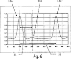
図6に低周波数レンジに変換された受信信号の図を示す。パルス列のこの期間には、第1スタートパルス15aとストップパルス16aとが含まれており、この図では、L i である時間拡張したパルス間隔22を有する後続の第2のスタートパルス15a’も識別できる。ここで求めるべき測定量は、時間であり、即ち第1スタートパルス16aとストップパルス15bとの間の遅延21である。ADコンバータによるサンプリングの後に、遅延21は、ひいてはサイクルx i は、遅延21とTi=Li/cとの間の比として計算することができる。目標物までの距離の計算は、上記関係(5)によって実行される。
D=Ni・Li+xi・Li
FIG. 6 shows a received signal converted into the low frequency range. The duration of the pulse train, includes a
D = N i · L i + x i · L i
ターゲットが複数ある場合、上記の1つの第1ストップパルスに加えて、変調送信周波数Fi毎に別々に測定することができるサイクルx i を有する別の複数のストップパルスが発生する。段状になった複数の目標物への距離を測定できるという可能性は、本発明の装置の殊に大きな長所である。 Targets plurality of cases, in addition to one of the first stop pulse of the another plurality of stop pulse having a cycle x i that can be measured separately for each modulation transmission frequency F i is generated. Possibility of being able to measure the distance to a plurality of targets became stepped is particularly great advantage of the apparatus of the present invention.
図7には、ヘテロダインサブサンプリングの効果が説明されている。上記の装置がただ1つの高周波数ミキサーしか備えていない場合、信号エネルギーの一部は失われる。この損失を伴う効果は、個所24において読みとれ、ここではミキサーの制御パルスがスタートパルスとストップパルスの間になる。これを避けるため、受信チャネルにおいて複数のミキサーモジュールが互いに並列に用いられる。制御信号のこの位相は、平行ミキサーの個数の一部だけ互いに対してシフトしている。このことによって保証されるのは、上記の複数のミキサーのうちの少なくとも1つのミキサーが、パルス周期T i 当たりに有効な信号サンプリング23を行い、これによって信号エネルギーが失われないことである。このような受信装置の感度は、パルス走行時間計の感度に匹敵し、従って従来の位相計の感度とは格段に異なる。
7 shows the effect of heterodyne subsampling is described. If the above equipment is not only provided with only one high-frequency mixer, a portion of the signal energy is lost. Effect with this loss, be read in
上記のコンポーネントの種々異なる配置構成または複数の原理は、択一的または補足的に組み合わせられることは当業者にとって自明のことである。さらに上記の装置の実施例は、ヘテロダイン又はホモダインの構造で構成することも可能である。 Various different arrangements or more principles of the components, be combined one or complementarily-option is obvious that those skilled in the art. Furthermore , the embodiments of the apparatus described above can also be configured with a heterodyne or homodyne structure.
Claims (21)
該測定方法は、
− 光の形態のパルス状の電磁ビーム(ES)を少なくとも1つのパルス繰り返し周波数で送信するステップを有しており、ただし当該の送信は、
・少なくとも1つの測定すべき目標までの装置外部の測定区間と、
・装置内部の参照区間(6)とを介して行われ、
ただし、前記参照区間(6)を介して導かれるビーム(IS)により、少なくとも1つのスタートパルスが定められ、前記測定区間を介して導かれるビーム(RS)により、少なくとも1つのストップパルスが定められ、
前記の測定方法にはさらに
− 前記目標によって後方散乱されたビーム(RS)と、前記参照区間を介して導かれたビーム(IS)とを受光するステップとを有しており、ただし、前記目標によって後方散乱されたビーム(RS)と、前記参照区間を介して導かれるビーム(IS)とを並行して受光して、受信信号(17)が、前記目標によって後方散乱されたビーム(RS)の成分と、前記参照区間を介して導かれたビーム(IS)の成分とを有し、かつ前記ビームが前記の受信信号(17)に変換されるようにし、
さらに前記測定方法には、
− 当該受信信号(17)から前記少なくとも1つの目標までの少なくとも1つの距離を求めるステップが含まれている、高精度距離測定方法において、
少なくとも2つのパルス繰り返し周波数に相応するパルス間隔L i ,L j および正の整数N i ,N j を選択して、関係式
N i ・L i < D max および
N j ・L j < D max ならびに
(整数N i ,N j の最小公倍数)・L i ≧ D max および
(整数N i ,N j の最小公倍数)・L j ≧ D max
が満たされるようにし、ただしD max はあらかじめ定めた一義領域であり、
前記少なくとも1つのパルス繰り返し周波数は可変でありかつ各測定距離に依存して選択されて、当該パルス繰り返し周波数のスタートパルスおよびストップパルスとが重ならないようにしたことを特徴とする
高精度距離測定方法。In the high-precision distance measurement method,
The measurement method is:
-Transmitting a pulsed electromagnetic beam (ES) in the form of light at at least one pulse repetition frequency, wherein said transmission comprises:
A measurement interval outside the device to at least one target to be measured;
-Via the reference section (6) inside the device,
However, at least one start pulse is defined by the beam (IS) guided through the reference section (6), and at least one stop pulse is defined by the beam (RS) guided through the measurement section. ,
The measurement method further comprises the step of: receiving a beam (RS) backscattered by the target and a beam (IS) guided through the reference section, wherein the target by the backscattered beam (RS), and a beam (iS) guided via the reference section by receiving and concurrency, the received signal (17), by the target backscattered beam (RS ) And a beam (IS) component guided through the reference interval, and the beam is converted into the received signal (17),
Furthermore, the measurement method includes:
-A high precision distance measuring method comprising the step of determining at least one distance from said received signal (17) to said at least one target;
Select a pulse interval L i , L j and a positive integer N i , N j corresponding to at least two pulse repetition frequencies,
N i · L i < D max and
N j · L j < D max and
( The least common multiple of integers N i and N j ) · L i ≧ D max and
( Least common multiple of integers N i and N j ) · L j ≧ D max
Where D max is a predetermined unambiguous region,
The at least one pulse repetition frequency is variable and is selected depending on each measurement distance so that a start pulse and a stop pulse of the pulse repetition frequency do not overlap with each other. .
請求項1記載の距離測定方法。The distance measuring method according to claim 1, characterized in that the received signal (17) is down-converted to an output signal (14) having a frequency lower than the pulse repetition frequency.
|Ni・Li−Nj・Lj|≧2・パルス幅
が満たされ、ただしNiとNjは、正の整数であって、
|Ni・Li−Nj・Lj|<1/2・min(Li,Lj)
であることを特徴とする
請求項1又は2に記載の距離測定方法。The pre Kipa pulse repetition frequency, selected in the range of sub et beforehand determined frequency bandwidth, for many combinations as possible of the corresponding pulse interval (22) L i and L j, conditions | N i · L i −N j · L j | ≧ 2 · pulse width is satisfied, where N i and N j are positive integers,
| N i · L i −N j · L j | <1/2 · min (L i , L j )
Distance measuring method according to claim 1 or 2, characterized in the Der Turkey.
請求項2または3に記載の距離測定方法。And at least one pulse and, wherein the benzalkonium a reference signal by correlation of the output signal having the low frequency (14),
The distance measuring method according to claim 2 or 3 .
請求項1ないし4のいずれか1に記載の距離測定方法。Down-converting the received signal (17) simultaneously with and in parallel with at least two mixer signals (18) out of phase to obtain at least two low-frequency signals,
The distance measuring method according to any one of claims 1 to 4 .
請求項1記載の距離測定方法。Combining the at least two low frequency signals in-phase and additively,
The distance measuring method according to claim 1 .
請求項1記載の距離測定方法。 The beam back-scattered by the target (RS) and the beam guided through the reference section (IS) are detected in parallel by a single common light receiver,
The distance measuring method according to claim 1 .
請求項1に記載の距離測定方法。The distance measuring method according to claim 1.
請求項1に記載の距離測定方法。The distance measuring method according to claim 1.
請求項4に記載の距離測定方法。The distance measuring method according to claim 4.
請求項4に記載の距離測定方法。The reference signal is a synthesized reference signal.
The distance measuring method according to claim 4.
該プログラムコードは、機械読み出し可能な媒体に保存されるか又は、電磁波によって具体化されており、前記プログラムがコンピュータによって実行される場合に、請求項1ないし7のいずれか1に記載の方法を実行することを特徴とする、
コンピュータプログラム。 Oite to a computer program with a program code,
The program code, or stored to a machine-readable medium, which is embodied by an electromagnetic wave, if the previous SL program is executed by a computer, according to any one of claims 1 to 7 METHOD Which is characterized by
Computer program.
該装置は、少なくとも
− 光の形態のビーム(ES)を形成しかつ放射するためパルス式ビーム源(5)と、
− 装置内部の参照区間(6)とを有しており、ただし前記ビームは、同時に装置外部の測定区間を介して少なくとも1つの測定すべき目標に向けて放射可能であり、かつ装置内部の参照区間(6)を介して放射可能であり、
前記装置はさらに
− ビームを受信して少なくとも1つの受信信号(17)に変換する少なくとも1つの受光器(7)を有しており、ただし前記目標によって後方散乱されたビーム(RS)および前記参照区間を介して導かれたビーム(IS)は共通に検出されて、前記受信信号(17)が、前記目標から後方散乱されたビーム(RS)および前記参照区間を介して導かれたビーム(IS)の成分を有するようにし、
前記装置はさらに
− 前記受信信号(17)を処理するための信号プロセッサ(μP)を有している、距離測定装置において、
前記ビーム源(5)を設計して、少なくとも2つのパルス繰り返し周波数を有するビームが放射できるようにし、ただし当該繰り返し周波数のうちの少なくとも1つは設定可能であるようにし、
前記パルス繰り返し周波数を選択して、あらかじめ定めた一義領域において少なくとも2つのパルス繰り返し周波数が存在するようにしかつ当該パルス繰り返し周波数のストップパルスが時間的に互いに重なり合わないようにしたことを特徴とする、
請求項1ないし11のいずれか1項に記載の方法を実行するための距離測定装置。A distance measuring device,
The apparatus comprises a pulsed beam source (5) for forming and emitting a beam (ES) in the form of at least light .
A reference zone (6) inside the device, wherein said beam can simultaneously radiate towards at least one target to be measured via a measurement zone outside the device, and a reference inside the device Can radiate via section (6),
Said device further comprises: at least one receiver (7 ) for receiving the beam and converting it into at least one received signal (17), provided that the beam (RS) backscattered by said target and said reference The beam (IS) guided through the section is commonly detected, and the received signal (17) is back-scattered from the target (RS) and the beam (IS) guided through the reference section (IS). ) Ingredients,
The device further comprises: a distance measuring device comprising a signal processor (μP) for processing the received signal (17) ;
Designed the beam source (5), to allow beam radiation having at least two pulse repetition frequencies, provided that at least one of the repetition frequency is a configurable der so that,
The pulse repetition frequency is selected so that at least two pulse repetition frequencies exist in a predetermined unambiguous region and stop pulses of the pulse repetition frequency do not overlap each other in time. ,
Distance measuring apparatus for carrying out the method according to any one of claims 1 to 11.
|Ni・Li−Nj・Lj|≧2・パルス幅
が満たされ、ただしNiとNjは、正の整数であることを特徴とする、
請求項13記載の距離測定装置。The pulse repetition frequency is selected and the condition | N i · L i −N j · L j | ≧ 2 for as many combinations as possible of the corresponding pulse interval (22) L i and L j. pulse width is satisfied, provided that N i and N j is characterized by a positive integer,
The distance measuring device according to claim 13 .
請求項13または14に記載の距離測定装置。Characterized in that it comprises at least one mixer (9, 9a-d) for down-converting the received signal (17) into a low-frequency output signal (14),
The distance measuring device according to claim 13 or 14 .
各ミキサーは、加算的に累算される信号による同相の時間拡張作用を有するサブサンプリングを実行することを特徴とする、
請求項15記載の距離測定装置。 The at least one mixer (9, 9a-d) is a pulsed analog mixer that is a subsampler for time extending the received signal (17);
Each mixer is characterized in that it performs sub-sampling with in-phase time expansion by the additively accumulated signal ,
The distance measuring device according to claim 15 .
請求項13ないし16のいずれか1項に記載の距離測定装置。The beam source (5) is a CW semiconductor laser,
Distance measuring device according to any one of claims 13 to 16.
請求項13ないし17のいずれか1項に記載の距離測定装置。As a multi-channel heterodyne device, comprising at least two electronic signal mixers operating in different phases and connected in parallel,
Distance measuring device according to any one of claims 13 to 17.
請求項13に記載の距離測定装置。The distance measuring device according to claim 13.
請求項13に記載の距離測定装置。The distance measuring device according to claim 13.
請求項13に記載の距離測定装置。The distance measuring device according to claim 13.
Applications Claiming Priority (3)
| Application Number | Priority Date | Filing Date | Title |
|---|---|---|---|
| EP04030085A EP1672382A1 (en) | 2004-12-18 | 2004-12-18 | Method for single channel heterodyne distance measurement |
| EP04030085.7 | 2004-12-18 | ||
| PCT/EP2005/013242 WO2006063740A1 (en) | 2004-12-18 | 2005-12-09 | Single-channel heterodyne distance measuring method |
Publications (3)
| Publication Number | Publication Date |
|---|---|
| JP2008524563A JP2008524563A (en) | 2008-07-10 |
| JP2008524563A5 JP2008524563A5 (en) | 2012-06-21 |
| JP5108526B2 true JP5108526B2 (en) | 2012-12-26 |
Family
ID=34927846
Family Applications (1)
| Application Number | Title | Priority Date | Filing Date |
|---|---|---|---|
| JP2007545908A Active JP5108526B2 (en) | 2004-12-18 | 2005-12-09 | Single channel heterodyne distance measurement method |
Country Status (6)
| Country | Link |
|---|---|
| US (1) | US7623222B2 (en) |
| EP (2) | EP1672382A1 (en) |
| JP (1) | JP5108526B2 (en) |
| CN (1) | CN101080647B (en) |
| AT (1) | ATE512374T1 (en) |
| WO (1) | WO2006063740A1 (en) |
Cited By (1)
| Publication number | Priority date | Publication date | Assignee | Title |
|---|---|---|---|---|
| JP2008524562A (en) * | 2004-12-18 | 2008-07-10 | ライカ ジオシステムズ アクチェンゲゼルシャフト | Electronic measurement method |
Families Citing this family (45)
| Publication number | Priority date | Publication date | Assignee | Title |
|---|---|---|---|---|
| US7714990B2 (en) * | 2004-12-16 | 2010-05-11 | Hilti Aktiengesellschaft | Hand-held laser distance measuring device with a pulse reflection mixing method |
| USRE46672E1 (en) | 2006-07-13 | 2018-01-16 | Velodyne Lidar, Inc. | High definition LiDAR system |
| NL2002116C (en) * | 2008-10-20 | 2010-04-21 | Stichting Noble House | METHOD FOR DETERMINING THE PRESENCE OF A TRANSMITTER AND A RECEIVER AND A SYSTEM FURNISHED THEREFORE. |
| DE102009012646A1 (en) * | 2009-03-11 | 2010-09-23 | Amt Gmbh | distance measurement |
| US8399819B2 (en) * | 2009-03-31 | 2013-03-19 | Osram Sylvania Inc. | Current source to drive a light source in an optical sensor system |
| FI122454B (en) * | 2009-08-27 | 2012-01-31 | Outotec Oyj | Method and equipment for measuring the level of material beds movable on conveyor belts |
| CA2781237C (en) | 2009-12-22 | 2016-02-23 | Leica Geosystems Ag | Highly accurate distance measurement device |
| US9100113B2 (en) * | 2011-04-26 | 2015-08-04 | Forschungsverbund Berlin E.V. | Auto-heterodyne receiver |
| CN102221355B (en) * | 2011-05-31 | 2012-09-05 | 哈尔滨工业大学 | Device and method for measuring laser incident angle by sinusoidally modulating multi-beam laser heterodyne with Doppler galvanometer |
| CN102221356B (en) * | 2011-05-31 | 2014-03-12 | 哈尔滨工业大学 | Device and method for measuring laser incident angle by sinusoidally modulating multi-beam laser heterodyne secondary harmonics with Doppler galvanometer |
| US8988660B2 (en) * | 2011-06-29 | 2015-03-24 | Silicon Laboratories Inc. | Optical detector |
| JP5753449B2 (en) * | 2011-06-30 | 2015-07-22 | 株式会社トプコン | Lightwave distance measuring method and lightwave distance apparatus |
| EP2589980A1 (en) | 2011-11-04 | 2013-05-08 | Leica Geosystems AG | Distance sensor |
| EP2597483B8 (en) | 2011-11-25 | 2017-06-07 | Safran Vectronix AG | Distance sensor |
| EP2600168A1 (en) | 2011-12-01 | 2013-06-05 | Leica Geosystems AG | Distance sensor |
| EP2637038B1 (en) | 2012-03-07 | 2017-01-18 | Vectronix AG | Distance sensor |
| EP2680029A1 (en) * | 2012-06-27 | 2014-01-01 | Leica Geosystems AG | Distance measuring method and distance meter |
| EP2680028A1 (en) | 2012-06-27 | 2014-01-01 | Leica Geosystems AG | Distance measuring method and distance meter |
| US20140149023A1 (en) * | 2012-11-29 | 2014-05-29 | Ford Global Technologies, Llc | Method and system for engine position control |
| US9664786B2 (en) | 2013-08-21 | 2017-05-30 | Selex Es Inc. | Method and apparatus for distance measuring equipment (DME/normal) using alternative pulse shapes |
| EP2843440B1 (en) | 2013-08-28 | 2018-11-28 | Safran Vectronix AG | Stabilised distance measurement in an observation device |
| WO2015098469A1 (en) * | 2013-12-27 | 2015-07-02 | 株式会社リコー | Distance measuring apparatus, electronic apparatus, distance measuring method, and distance measuring program |
| CN105890575B (en) * | 2014-12-10 | 2019-02-12 | 青岛理工大学 | Common and particular surroundings artificial intelligence machine visual identity method and device |
| FR3034513A1 (en) * | 2015-04-02 | 2016-10-07 | Stmicroelectronics (Grenoble 2) Sas | |
| GB201514249D0 (en) * | 2015-08-12 | 2015-09-23 | Trw Ltd | Processing received radiation reflected from a target |
| WO2017127230A1 (en) | 2016-01-22 | 2017-07-27 | Mezmeriz Inc. | Signal detection apparatus, method, and applications |
| US10627490B2 (en) | 2016-01-31 | 2020-04-21 | Velodyne Lidar, Inc. | Multiple pulse, LIDAR based 3-D imaging |
| WO2017164989A1 (en) | 2016-03-19 | 2017-09-28 | Velodyne Lidar, Inc. | Integrated illumination and detection for lidar based 3-d imaging |
| CA3024510C (en) | 2016-06-01 | 2022-10-04 | Velodyne Lidar, Inc. | Multiple pixel scanning lidar |
| CA3057988A1 (en) | 2017-03-31 | 2018-10-04 | Velodyne Lidar, Inc. | Integrated lidar illumination power control |
| CN110520753B (en) | 2017-04-13 | 2023-05-30 | 三菱电机株式会社 | Laser radar device |
| WO2018208843A1 (en) | 2017-05-08 | 2018-11-15 | Velodyne Lidar, Inc. | Lidar data acquisition and control |
| JP6991034B2 (en) * | 2017-10-19 | 2022-01-12 | 株式会社トプコン | Method for determining modulation frequency of light wave rangefinder and feedback signal |
| US11294041B2 (en) * | 2017-12-08 | 2022-04-05 | Velodyne Lidar Usa, Inc. | Systems and methods for improving detection of a return signal in a light ranging and detection system |
| EP3599485B1 (en) | 2018-07-23 | 2024-03-27 | MicroVision, Inc. | Method and device for optically measuring distances |
| US10712434B2 (en) | 2018-09-18 | 2020-07-14 | Velodyne Lidar, Inc. | Multi-channel LIDAR illumination driver |
| US11082010B2 (en) | 2018-11-06 | 2021-08-03 | Velodyne Lidar Usa, Inc. | Systems and methods for TIA base current detection and compensation |
| US11885958B2 (en) | 2019-01-07 | 2024-01-30 | Velodyne Lidar Usa, Inc. | Systems and methods for a dual axis resonant scanning mirror |
| CN113424074A (en) * | 2019-02-13 | 2021-09-21 | 拉姆达 4发展有限公司 | Run time measurement based on frequency switching |
| CN110221308B (en) * | 2019-03-04 | 2021-04-30 | 中国电子科技集团公司第十一研究所 | Coherent pulse laser ranging method, related device and storage medium |
| US10613203B1 (en) | 2019-07-01 | 2020-04-07 | Velodyne Lidar, Inc. | Interference mitigation for light detection and ranging |
| JP2021156688A (en) * | 2020-03-26 | 2021-10-07 | ソニーセミコンダクタソリューションズ株式会社 | Distance measuring system |
| FR3119683B1 (en) | 2021-02-10 | 2024-03-08 | Bertin Technologies Sa | Observation system and method and method of manufacturing such a system |
| CN115236685B (en) * | 2022-09-21 | 2022-12-23 | 成都量芯集成科技有限公司 | Phase method laser range unit |
| CN116381597B (en) * | 2023-05-29 | 2023-08-25 | 成都唯博星辰科技有限公司 | Broadband single-channel direction finding system and implementation method |
Family Cites Families (7)
| Publication number | Priority date | Publication date | Assignee | Title |
|---|---|---|---|---|
| JPS60244881A (en) * | 1984-05-21 | 1985-12-04 | Tech Res & Dev Inst Of Japan Def Agency | Range tracking radar |
| JPS6443784A (en) * | 1987-08-12 | 1989-02-16 | Japan Tech Res & Dev Inst | Distance decision device for pulse radar |
| US5428439A (en) * | 1992-09-23 | 1995-06-27 | The Texas A&M University System | Range measurement system |
| US5347525A (en) * | 1993-02-19 | 1994-09-13 | Sri International | Generation of multiple stabilized frequency references using a mode-coupled laser |
| US5889490A (en) * | 1996-08-05 | 1999-03-30 | Wachter; Eric A. | Method and apparatus for improved ranging |
| DE10112833C1 (en) * | 2001-03-16 | 2003-03-13 | Hilti Ag | Method and device for electro-optical distance measurement |
| EP1450128A1 (en) * | 2003-02-19 | 2004-08-25 | Leica Geosystems AG | Method and device for extracting geodesic distance information |
-
2004
- 2004-12-18 EP EP04030085A patent/EP1672382A1/en not_active Withdrawn
-
2005
- 2005-12-09 EP EP05817590A patent/EP1825294B1/en active Active
- 2005-12-09 AT AT05817590T patent/ATE512374T1/en active
- 2005-12-09 JP JP2007545908A patent/JP5108526B2/en active Active
- 2005-12-09 WO PCT/EP2005/013242 patent/WO2006063740A1/en active Application Filing
- 2005-12-09 CN CN2005800434851A patent/CN101080647B/en active Active
- 2005-12-09 US US11/721,977 patent/US7623222B2/en active Active
Cited By (1)
| Publication number | Priority date | Publication date | Assignee | Title |
|---|---|---|---|---|
| JP2008524562A (en) * | 2004-12-18 | 2008-07-10 | ライカ ジオシステムズ アクチェンゲゼルシャフト | Electronic measurement method |
Also Published As
| Publication number | Publication date |
|---|---|
| CN101080647A (en) | 2007-11-28 |
| US7623222B2 (en) | 2009-11-24 |
| WO2006063740A1 (en) | 2006-06-22 |
| JP2008524563A (en) | 2008-07-10 |
| US20080304043A1 (en) | 2008-12-11 |
| EP1672382A1 (en) | 2006-06-21 |
| EP1825294B1 (en) | 2011-06-08 |
| CN101080647B (en) | 2012-04-11 |
| EP1825294A1 (en) | 2007-08-29 |
| ATE512374T1 (en) | 2011-06-15 |
Similar Documents
| Publication | Publication Date | Title |
|---|---|---|
| JP5108526B2 (en) | Single channel heterodyne distance measurement method | |
| JP2008524563A5 (en) | ||
| JP5590771B2 (en) | Electronic measurement method | |
| JP6410258B2 (en) | Light wave distance meter | |
| EP1560041B1 (en) | Processing apparatus for pulsed signal and processing method for pulsed signal and program therefor | |
| JP2006521536A (en) | High-precision distance measuring apparatus and method | |
| US7911589B2 (en) | Optical distance measuring method and corresponding optical distance measurement device | |
| US6031601A (en) | Code-space optical electronic distance meter | |
| RU2419813C2 (en) | Method and device for measuring distance | |
| US5742379A (en) | Device and method for electronically measuring distances | |
| JP2008524562A5 (en) | ||
| JP2006521536A5 (en) | ||
| US7982859B2 (en) | Method and device for deriving geodetic distance data | |
| JP2909742B2 (en) | Delay time measuring device | |
| JP5584400B2 (en) | Handheld laser distance measuring device using pulse reflection mixing method | |
| JP4104991B2 (en) | Light wave distance meter | |
| US9041918B2 (en) | Measuring apparatus and referencing method for a digital laser distance meter, and laser distance meter | |
| CN105652282A (en) | Laser phase ranging module | |
| Bazin et al. | A new laser range-finder based on FMCW-like method | |
| JP6653052B2 (en) | Laser ranging device and laser ranging method | |
| JP2008051523A (en) | Radar system and distance measuring method | |
| JP6609360B2 (en) | Light wave distance meter | |
| JP2005156175A (en) | Laser range finder | |
| JPS60253992A (en) | Range measuring device |
Legal Events
| Date | Code | Title | Description |
|---|---|---|---|
| A621 | Written request for application examination |
Free format text: JAPANESE INTERMEDIATE CODE: A621 Effective date: 20081024 |
|
| RD03 | Notification of appointment of power of attorney |
Free format text: JAPANESE INTERMEDIATE CODE: A7423 Effective date: 20091015 |
|
| A521 | Request for written amendment filed |
Free format text: JAPANESE INTERMEDIATE CODE: A821 Effective date: 20091021 |
|
| RD04 | Notification of resignation of power of attorney |
Free format text: JAPANESE INTERMEDIATE CODE: A7424 Effective date: 20091021 |
|
| RD04 | Notification of resignation of power of attorney |
Free format text: JAPANESE INTERMEDIATE CODE: A7424 Effective date: 20101228 |
|
| A131 | Notification of reasons for refusal |
Free format text: JAPANESE INTERMEDIATE CODE: A131 Effective date: 20111104 |
|
| A601 | Written request for extension of time |
Free format text: JAPANESE INTERMEDIATE CODE: A601 Effective date: 20120206 |
|
| A602 | Written permission of extension of time |
Free format text: JAPANESE INTERMEDIATE CODE: A602 Effective date: 20120213 |
|
| A601 | Written request for extension of time |
Free format text: JAPANESE INTERMEDIATE CODE: A601 Effective date: 20120305 |
|
| A602 | Written permission of extension of time |
Free format text: JAPANESE INTERMEDIATE CODE: A602 Effective date: 20120312 |
|
| A601 | Written request for extension of time |
Free format text: JAPANESE INTERMEDIATE CODE: A601 Effective date: 20120404 |
|
| A602 | Written permission of extension of time |
Free format text: JAPANESE INTERMEDIATE CODE: A602 Effective date: 20120411 |
|
| A521 | Request for written amendment filed |
Free format text: JAPANESE INTERMEDIATE CODE: A523 Effective date: 20120507 |
|
| A524 | Written submission of copy of amendment under article 19 pct |
Free format text: JAPANESE INTERMEDIATE CODE: A524 Effective date: 20120507 |
|
| TRDD | Decision of grant or rejection written | ||
| A01 | Written decision to grant a patent or to grant a registration (utility model) |
Free format text: JAPANESE INTERMEDIATE CODE: A01 Effective date: 20120907 |
|
| A01 | Written decision to grant a patent or to grant a registration (utility model) |
Free format text: JAPANESE INTERMEDIATE CODE: A01 |
|
| A61 | First payment of annual fees (during grant procedure) |
Free format text: JAPANESE INTERMEDIATE CODE: A61 Effective date: 20121005 |
|
| R150 | Certificate of patent or registration of utility model |
Ref document number: 5108526 Country of ref document: JP Free format text: JAPANESE INTERMEDIATE CODE: R150 Free format text: JAPANESE INTERMEDIATE CODE: R150 |
|
| FPAY | Renewal fee payment (event date is renewal date of database) |
Free format text: PAYMENT UNTIL: 20151012 Year of fee payment: 3 |
|
| R250 | Receipt of annual fees |
Free format text: JAPANESE INTERMEDIATE CODE: R250 |
|
| R250 | Receipt of annual fees |
Free format text: JAPANESE INTERMEDIATE CODE: R250 |
|
| R250 | Receipt of annual fees |
Free format text: JAPANESE INTERMEDIATE CODE: R250 |
|
| R250 | Receipt of annual fees |
Free format text: JAPANESE INTERMEDIATE CODE: R250 |
|
| R250 | Receipt of annual fees |
Free format text: JAPANESE INTERMEDIATE CODE: R250 |
|
| R250 | Receipt of annual fees |
Free format text: JAPANESE INTERMEDIATE CODE: R250 |
|
| R250 | Receipt of annual fees |
Free format text: JAPANESE INTERMEDIATE CODE: R250 |
|
| R250 | Receipt of annual fees |
Free format text: JAPANESE INTERMEDIATE CODE: R250 |
|
| R250 | Receipt of annual fees |
Free format text: JAPANESE INTERMEDIATE CODE: R250 |