JP5106629B2 - Slider for slide fastener with automatic stop device - Google Patents
Slider for slide fastener with automatic stop device Download PDFInfo
- Publication number
- JP5106629B2 JP5106629B2 JP2010509977A JP2010509977A JP5106629B2 JP 5106629 B2 JP5106629 B2 JP 5106629B2 JP 2010509977 A JP2010509977 A JP 2010509977A JP 2010509977 A JP2010509977 A JP 2010509977A JP 5106629 B2 JP5106629 B2 JP 5106629B2
- Authority
- JP
- Japan
- Prior art keywords
- slider
- mounting column
- portions
- handle
- handle holder
- Prior art date
- Legal status (The legal status is an assumption and is not a legal conclusion. Google has not performed a legal analysis and makes no representation as to the accuracy of the status listed.)
- Active
Links
Images


Classifications
-
- A—HUMAN NECESSITIES
- A44—HABERDASHERY; JEWELLERY
- A44B—BUTTONS, PINS, BUCKLES, SLIDE FASTENERS, OR THE LIKE
- A44B19/00—Slide fasteners
- A44B19/24—Details
- A44B19/26—Sliders
- A44B19/30—Sliders with means for locking in position
- A44B19/306—Sliders with means for locking in position in the form of a locking spring member actuated by the pull member
-
- Y—GENERAL TAGGING OF NEW TECHNOLOGICAL DEVELOPMENTS; GENERAL TAGGING OF CROSS-SECTIONAL TECHNOLOGIES SPANNING OVER SEVERAL SECTIONS OF THE IPC; TECHNICAL SUBJECTS COVERED BY FORMER USPC CROSS-REFERENCE ART COLLECTIONS [XRACs] AND DIGESTS
- Y10—TECHNICAL SUBJECTS COVERED BY FORMER USPC
- Y10T—TECHNICAL SUBJECTS COVERED BY FORMER US CLASSIFICATION
- Y10T24/00—Buckles, buttons, clasps, etc.
- Y10T24/25—Zipper or required component thereof
- Y10T24/2561—Slider having specific configuration, construction, adaptation, or material
- Y10T24/2566—Slider having specific configuration, construction, adaptation, or material including position locking-means attached thereto
- Y10T24/257—Slider having specific configuration, construction, adaptation, or material including position locking-means attached thereto having surface engaging element shifted by reorientation of pull tab
- Y10T24/2571—Resilient or spring biased element
-
- Y—GENERAL TAGGING OF NEW TECHNOLOGICAL DEVELOPMENTS; GENERAL TAGGING OF CROSS-SECTIONAL TECHNOLOGIES SPANNING OVER SEVERAL SECTIONS OF THE IPC; TECHNICAL SUBJECTS COVERED BY FORMER USPC CROSS-REFERENCE ART COLLECTIONS [XRACs] AND DIGESTS
- Y10—TECHNICAL SUBJECTS COVERED BY FORMER USPC
- Y10T—TECHNICAL SUBJECTS COVERED BY FORMER US CLASSIFICATION
- Y10T24/00—Buckles, buttons, clasps, etc.
- Y10T24/25—Zipper or required component thereof
- Y10T24/2561—Slider having specific configuration, construction, adaptation, or material
- Y10T24/2586—Slider having specific configuration, construction, adaptation, or material including pull tab attaching means
Description
本発明は、スライドファスナー用スプリング体を装着した自動停止装置を有するスライドファスナー用のスライダーに係わり、特に、スプリング体を保持する引手保持体の前後左右方向へのズレを防止し、スライダーの小型化を図るとともに、製造する材料費を低減させ、外観意匠性を大幅に向上させた自動停止装置付のスライダーに関する。 The present invention relates to a slider for a slide fastener having an automatic stop device equipped with a spring body for a slide fastener, and in particular, prevents a displacement of a handle holding body for holding a spring body in the front-rear and left-right directions, thereby reducing the size of the slider. In addition, the present invention relates to a slider with an automatic stop device that reduces the cost of materials to be manufactured and greatly improves the appearance design.
従来から、スライドファスナー用のスライダーとして自動停止装置を備えたスライダーが多用されている。自動停止装置を備えたスライダーでは、ファスナーチェーンの務歯列を噛合及び開離させるスライダー胴体に対して、スライダー胴体を摺動させる引手を操作することで、スライダー胴体の移動停止と停止状態の解除とを行うことができる。 Conventionally, a slider provided with an automatic stop device has been frequently used as a slider for a slide fastener. For sliders equipped with an automatic stop device, the slider body moves and stops when the slider body slides against the slider body that engages and separates the dentition of the fastener chain. And can be done.
そして、引手を操作することで、長尺の微小な弾性金属板材から構成されているスプリング体の爪部を、スプリング体の付勢力によってファスナーチェーンの務歯列の一部に係合させ、スライダーの移動を停止させておくことができる。また、爪部に対するスプリング体の付勢力を引手の操作によって解除することによって、スライダーの移動停止状態を解除することができる。 Then, by operating the pull handle, the claw portion of the spring body made of a long minute elastic metal plate is engaged with a part of the dentition row of the fastener chain by the biasing force of the spring body, and the slider Can be stopped. Moreover, the movement stop state of the slider can be released by releasing the biasing force of the spring body against the claw portion by the operation of the pulling handle.
この種の自動停止装置付のスライダーにおける構造例としては、例えば本出願人により先に提案された自動停止装置付スライドファスナー用スライダー(特許文献1参照)などがある。 As an example of the structure of this type of slider with an automatic stop device, there is, for example, a slide fastener slider with an automatic stop device previously proposed by the present applicant (see Patent Document 1).
特許文献1に記載されたスライダーでは、スプリング体に設けたスプリング片の付勢力によって、スプリング体の爪部をファスナーチェーンの務歯列の一部と係合させることができる。そして、スプリング片からの付勢力に抗してスプリング体を持ち上げない限り、爪部はスプリング片の付勢力によって、ファスナーチェーンの務歯列の一部と係合したままの状態が維持される。
In the slider described in
手で引手を前方へ持ち上げると、あるいは引手を後方へ引っ張ると、スプリング片からの付勢力に抗してスプリング体を持ち上げることができ、スプリング体の爪部をファスナーチェーンの務歯間から離れさせることができる。そして、スライダーを摺動自在にできる。 When the handle is lifted forward by hand or pulled backward, the spring body can be lifted against the urging force from the spring piece, and the claw part of the spring body is separated from the engagement teeth of the fastener chain. be able to. The slider can be slid freely.
また、前方へ持ち上げていた引手、あるいは後方へ引っ張っていた引手を手放せば、スプリング片からの付勢力によって、爪部は再びファスナーチェーンの務歯間に自動的に挿入され、スライダーを停止状態にすることができる。 Also, if you release the handle that was lifted forward or pulled backward, the pawl is automatically inserted again between the engagement teeth of the fastener chain by the biasing force from the spring piece, and the slider is stopped. can do.
ところで、上記特許文献1に開示されたようなスプリング体は、バネ剛性の強い銅合金やステンレス鋼などの金属材料から構成されており、所定の断面形状を有する長尺の板材から断片を一部残して切抜くことで、スプリング片を備えたスプリング体を製造することができる。しかしながら、スプリング体は数mm程度の大きさを有する小片として構成されているため、前記形材の外周端縁に沿って打抜かれる幅や長さ寸法は更に小さなものになっている。
By the way, the spring body as disclosed in
このため、特許文献1に記載されたような従来からのスライダーでは、次に述べるような様々な不具合が生じていた。例えば、靭性の高い上述したような金属材料からスプリング体を形成するときには、スプリング片のような極めて小さい部品に対して、打抜加工や曲げ加工などを施すことになる。このため、打抜加工や曲げ加工などの加工中に、金属材料に対して亀裂が生じてしまったり、打抜パンチの刃が早期に摩耗してしまうなどの様々な不具合が生じていた。
For this reason, the conventional slider as described in
即ち、スプリング片の先端部に対して過度の力が加えられると、スプリング片が切損したり、あるいは亀裂が生じたりしていた。
このため、スプリング片の先端部に対する加工精度を高めて、形態の安定性を期待することが難しく、スプリング体製品を高精度に多量生産を行うには限界があった。That is, when an excessive force is applied to the tip of the spring piece, the spring piece is broken or cracked.
For this reason, it is difficult to increase the processing accuracy for the tip of the spring piece and to expect the stability of the form, and there is a limit to mass production of spring body products with high accuracy.
このような、従来からの問題を解決するため本願出願人によって、スライドファスナー用スプリング体の構成を改良したスライダーが、特許文献2記載のスライドファスナー用スプリング体を装着したスライダーとして提案されている。そして、特許文献2記載のスライダーでは、スプリング体を製造するための材料費や製作コストを低減することができ、しかも、スプリング体を製造するのに当たって安定した良好な生産性を実現することができる。また、スライダーとしての構造が簡単となり、安価でしかも良好な外観意匠性を有し、更に、安定した良好な自動停止機能を確保することができるとともに、スライダーの小型化をも実現させることができるといった利点を有している。 In order to solve such a conventional problem, the applicant of the present application has proposed a slider with an improved structure of the slide fastener spring body as a slider equipped with the slide fastener spring body described in Patent Document 2. In the slider described in Patent Document 2, the material cost and manufacturing cost for manufacturing the spring body can be reduced, and stable and good productivity can be realized in manufacturing the spring body. . In addition, the structure as a slider is simplified, it is inexpensive and has a good appearance design, a stable and good automatic stop function can be secured, and the slider can be downsized. It has the following advantages.
特許文献2記載のスライダーを本発明の従来例として、図9にはその斜視図を示している。図9に示すように、引手保持体51は、薄肉の長尺板材により構成されており、偏平な上壁部52の前後には、それぞれ同一曲率をもって滑らかに湾曲して形成された前後壁部53,54を有した構成になっている。そして、引手保持体51は、その側面視の形状が略横C字状となった、カバー体として構成されている。
FIG. 9 shows a perspective view of the slider described in Patent Document 2 as a conventional example of the present invention. As shown in FIG. 9, the
スライダー胴体60上面の前後には、前取付柱61と後取付柱62とが立設されている。各前後取付柱61,62にそれぞれ形成された図示せぬ被係止部には、上壁部52における前後壁部53,54の先端部内面に形成した図示せぬ係合片が、弾性的に係合することができる。また、前取付柱61と後取付柱62との間における空間部の一部を被って遮蔽する幅広の左右翼片55,55が、上壁部52から湾曲して下方に向かって突出している。また、前後取付柱61,62には、それぞれ左右一対の支持壁61a,62aが設けられている。以上が、特許文献2記載のスライダー50に関する概略的な構成である。
A
ところで、特許文献2記載のスライダー50の構成において、引手保持体51を中心とした外観形状、及び引手保持体51が外力の作用によって左右方向に移動してしまうのを防止する構成が、本発明との間で技術的な関連を有している。
By the way, in the configuration of the
そこで、特許文献2記載のスライダー50に関して、その内部構造に関しての説明は省略して、引手保持体51を中心とした外観形状、及び引手保持体51に作用する外力によって、引手保持体51が前後左右方向へ移動してしまうのを防止する構成について、説明を行っていく。
Therefore, the description of the internal structure of the
図9に示すように、引手保持体51の図示せぬ係合片を、前後取付柱61,62の図示せぬ被係止部に対して弾性的に係合させることで、引手保持体51は、前後取付柱61,62に係合してスライダー胴体の上部に装着されることになる。そして、引手保持体51を、前後取付柱61,62の対向面間に嵌着支持させることができる。しかも、引手保持体51の上壁部52及び前後壁部53,54におけるそれぞれの上面と、支持壁61a,62aにおけるそれぞれの上面とが、面一となるように配することができる。
As shown in FIG. 9, the
この構成により、引手保持体51の肉厚を必要最小限の肉厚として構成しておくことができ、スライダー50を小型化することや薄型化することができる。また、外観意匠性にも優れた、しかも商品価値の高いスライダー50を得ることができる。
With this configuration, the thickness of the
スライダー胴体60上面の前後に立設した前取付柱61及び後取付柱62には、内側に向かって向き合った一対の突起部61b,62bがそれぞれ形成されている。そして、引手保持体51に設けた左右一対の左右翼片55と上壁部52との間における稜線部(角部)には、欠落部56a,56bが形成されている。欠落部56a,56b は、左右翼片55における直線状の両側端面から内方に向かった凹陥状の段差として構成されている。
A pair of
そして、一対の突起部61b,62bを各欠落部56a,56b 内にそれぞれ嵌入して係着させることで、引手保持体51が外力の作用によって前後左右方向に移動してしまうのを防止している。
The pair of
スライダー50における上述した構成によって、前後及び左右方向のあらゆる方向から作用する外力に対して、引手保持体51がぐらつくことなく、強固に且つ確実に引手保持体51を前後取付柱61,62に装着しておくことができる。しかも、引手保持体51とスライダー胴体60との間に配設した図示せぬスプリング体のスプリング片を、円滑に且つ確実に保持しておくことができる。従って、自動停止装置付スライドファスナー用スライダー50の品質を、長期間にわたり安定して確保しておくことができる効果を有している。
特許文献2に開示されているスライダー50は、外観意匠性が優れた構成となっている。しかも、このスライダー50では、引手保持体51は、前後取付柱61,62の支持壁61a,62a間に配される構成になっているとともに、欠落部56a,56bと突起部61b,62bとを係着させておくことにより、引手保持体51が外力の作用によって前後左右方向に移動してしまうのを防止する構成となっている。
The
このため、スライダー50の外観形状において、支持壁61a,62aの側端面が、スライダー50の外側から視認可能になっているとともに、欠落部56a,56bと突起部61b,62b との係着状態もスライダー50の外側から視認可能になっている。
Therefore, in the external shape of the
そこで、支持壁61a,62aの側端面や欠落部56a,56b と突起部61b,62bとの係着状態が、外側から視認できなくした構成を得ることによって、自動停止装置付スライドファスナー用スライダーをよりシンプルな外形形状に構成することができ、しかも、外観意匠性においても更に優れた構成にすることができる。このように構成することによって、自動停止装置付スライドファスナー用スライダーを用いたスライドファスナー製品の価値を大いに高めることができる。
Therefore, by obtaining a configuration in which the side end surfaces of the
そこで、本発明では、特許文献2に開示されている自動停止装置付スライドファスナー用スライダーの奏する機能はそのまま奏させることができるようにした上で、引手保持体に形成した欠落部の構成を廃止し、しかも、支持壁61a,62aの側端面を外側から視認できなくして外観意匠性に優れた自動停止装置付スライドファスナー用スライダーを提供することにある。
Therefore, in the present invention, the function of the slider for the slide fastener with automatic stop device disclosed in Patent Document 2 can be performed as it is, and the configuration of the missing portion formed in the handle holder is abolished. And it is providing the slider for slide fasteners with an automatic stop device which was not visible from the outer side of the side walls of
上記目的を達成するために、本発明の自動停止装置付きスライドファスナー用スライダーでは、ファスナーチェーンの務歯列を噛合及び開離させるスライダー胴体と、前記スライダー胴体を摺動させる引手と、前記スライダー胴体の上部に装着支持され、前記スライダー胴体の上面との間で前記引手を移動可能に保持する引手保持体と、前記引手保持体の裏面と前記スライダー胴体との間に配されるスプリング体と、を備え、
前記スプリング体は、前記引手保持体の裏面と前記引手との間に弾接して配されるスプリング片と、前記引手の操作による前記スプリング片の弾性変形に基づいて、前記スライダー胴体の内部に通した前記ファスナーチェーンの務歯列の一部との係合及び係合解除を行う爪部と、を有し、
前記スライダー胴体上面の前後には、それぞれ被係合部が形成された前取付柱及び後取付柱が設けられ、前記引手保持体は、偏平な上壁部の前後に形成された前後壁部を有する側面視が略横C字状のカバー体として構成され、前記前後壁部の各先端部内面には、前記被係合部と弾性的に係合する係合片が形成されてなる自動停止装置付スライドファスナー用スライダーにおいて、
前記スライダーの左右幅方向において、前記引手保持体の幅寸法と、前記前取付柱及び後取付柱の幅寸法とは、略等しい幅寸法に構成され、前記引手保持体は、前記引手保持体の上壁部の左右両側から下方に突出し、前記前取付柱と前記後取付柱との間の空間部を被って遮蔽する左右翼片を有し、前記前取付柱及び前記後取付柱は、それぞれ前記前取付柱
及び後取付柱の左右端面に立設した支持壁を有し、
前記引手保持体と、前記前取付柱及び前記後取付柱のうち少なくとも一方の取付柱との間には、前記引手保持体の上壁部が左右方向に移動するのを規制する規制機構が設けられ、
前記規制機構は、前記スライダーの左右幅方向における前記左右翼片の内面側であって、前記左右翼片の側端面と前記前後壁部との間において、前記上壁部の裏面から下方に向かって突出した形状に構成されてなる係止部と、前記スライダーの左右幅方向における前記支持壁の内面側において、前記係止部を収納する形状に構成されてなる被係止部とから構成され、
前記引手保持体の前記各係合片を、それぞれ前記前取付柱の被係合部及び前記後取付柱の被係合部に係合させたとき、前記係止部と前記被係止部とは互いに係止状態となり、かつ前記引手保持体は、前記前取付柱及び後取付柱の側端面を覆い隠す状態に配されてなることを最も主要な特徴となしている。
In order to achieve the above object, in the slide fastener slider with an automatic stop device according to the present invention, a slider body that engages and separates the engagement teeth of a fastener chain, a puller that slides the slider body, and the slider body Mounted on and supported by the upper portion of the slider body, and a handle body that holds the handle movably between the upper surface of the slider body, and a spring body disposed between the back surface of the handle body and the slider body, With
The spring body passes through the inside of the slider body based on a spring piece arranged in elastic contact between the back surface of the handle holding body and the handle, and elastic deformation of the spring piece by the operation of the handle. A claw portion that engages with and disengages from a part of the dentition row of the fastener chain,
A front mounting column and a rear mounting column each having an engaged portion are provided on the front and back of the upper surface of the slider body, and the handle holder includes front and rear wall portions formed before and after a flat upper wall portion. The automatic stop is configured as a substantially horizontal C-shaped cover body having an engagement piece that is elastically engaged with the engaged portion on the inner surface of each of the front and rear wall portions. In the slider for slide fastener with device,
In the left-right width direction of the slider, the width dimension of the handle holder and the width dimension of the front mounting column and the rear mounting column are substantially equal to each other. The left and right wing pieces project downward from the left and right sides of the upper wall portion and cover the space between the front mounting column and the rear mounting column, and the front mounting column and the rear mounting column are respectively Front mounting post
And support walls erected on the left and right end faces of the rear mounting column,
A restriction mechanism is provided between the pull handle holder and at least one of the front mounting column and the rear mounting column to restrict the upper wall portion of the pull handle holder from moving in the left-right direction. And
The regulating mechanism is an inner surface side of the left and right wing pieces in the left and right width direction of the slider, and extends downward from the back surface of the upper wall portion between the side end surfaces of the left and right wing pieces and the front and rear wall portions. and the locking portion consisting configured to shape protruding Te, the inner surface of the support wall in the lateral width direction of the slider, is engaged portion Toka et structure consisting configured in a shape that houses the engagement portion ,
When the engaging pieces of the pulling holder are engaged with the engaged portion of the front mounting column and the engaged portion of the rear mounting column, respectively, the locking portion and the locked portion And the handle holders are arranged in a state of covering the side end faces of the front mounting column and the rear mounting column.
更に、本発明の自動停止装置付スライドファスナー用スライダーでは、前記係止部は、前記左右翼片から前記前後壁部方向に向かって延設された形状に構成され、前記被係止部は、前記支持壁の内面における前記前支持壁と前記後支持壁とが対峙する上部角隅部において、上方と側方とを開口した段差部として構成されてなることを主要な特徴となしている。 Furthermore, in the slider for a slide fastener with an automatic stop device of the present invention, the locking portion is configured in a shape extending from the left and right wing pieces toward the front and rear wall portions, and the locked portion is The main feature is that the upper corner portion of the inner surface of the support wall where the front support wall and the rear support wall face each other is configured as a stepped portion that opens upward and laterally.
更にまた、本発明の自動停止装置付スライドファスナー用スライダーでは、前記係止部は、前記左右翼片から前記前後壁部方向に向かって延設された形状に構成された第一係止部と、前記引手保持体の前記各係合片を、それぞれ前記前取付柱の被係合部及び前記後取付柱の被係合部に係合させたときに、前記支持壁の内面間に嵌入する第二係止部と、を有し、
前記被係止部は、前記第一係止部を係合させ、前記支持壁の内面における前記前支持壁と前記後支持壁とが対峙する上部角隅部において、上方と側方とを開口した段差部と、前記支持壁の内面における外周縁側の部位と、を有してなることを主要な特徴となしている。Furthermore, in the slide fastener slider with an automatic stop device of the present invention, the locking portion includes a first locking portion configured in a shape extending from the left and right wing pieces toward the front and rear wall portions. When the engaging pieces of the handle holder are engaged with the engaged portion of the front mounting column and the engaged portion of the rear mounting column, they are fitted between the inner surfaces of the support walls. A second locking portion,
The locked portion engages the first locking portion and opens upward and laterally at an upper corner where the front support wall and the rear support wall face each other on the inner surface of the support wall. The main feature is that it has a stepped portion and a portion on the outer peripheral edge side of the inner surface of the support wall.
また、本発明の自動停止装置付スライドファスナー用スライダーでは、前記上壁部の裏面からの突出量において、前記第一係止部における突出量が、前記第二係止部における突出量よりも大きいことを主要な特徴となしている。 Moreover, in the slider for slide fasteners with an automatic stop device of the present invention, the amount of protrusion at the first locking portion is larger than the amount of protrusion at the second locking portion in the protruding amount from the back surface of the upper wall portion. This is a key feature.
本発明の構成においても、特許文献2に開示されている自動停止装置付スライドファスナー用スライダーが奏している機能はそのまま奏することができる。しかも、本発明では、スライダーの左右幅方向において、引手保持体の幅寸法と前取付柱及び後取付柱の幅寸法とを、略等しい幅寸法に構成している。また、引手保持体に設けられた係止部と、少なくとも前取付柱又は後取付柱に設けられて、前記引手保持体の係止部を係止する被係止部と、によって、引手保持体の前後左右方向への移動を規制する規制機構を構成している。 Even in the configuration of the present invention, the function exhibited by the slide fastener-equipped slide fastener slider disclosed in Patent Document 2 can be performed as it is. Moreover, in the present invention, the width dimension of the handle holder and the width dimensions of the front mounting column and the rear mounting column are configured to be substantially equal in the width direction of the slider. Further, the handle holding body includes: a locking portion provided on the handle holding body; and a locked portion that is provided at least on the front mounting column or the rear mounting column and locks the locking portion of the handle holding body. A restricting mechanism that restricts movement of the front and rear and right and left is configured.
引手保持体の幅寸法と前取付柱及び後取付柱の幅寸法とを略等しい幅寸法に構成した上で、更に上記規制機構を設けておくことによって、特許文献2に開示されている自動停止装置付スライドファスナー用スライダーが備えていた、引手保持体に形成した欠落部及び、前取付柱及び後取付柱から内側に向かって向き合った一対の突起部の構成を廃止することができる。 The automatic stop disclosed in Patent Document 2 is made by configuring the width dimension of the handle holding body and the width dimension of the front mounting column and the rear mounting column to be substantially equal, and further providing the restriction mechanism. The configuration of the missing portion formed on the handle holder and the pair of protrusions facing inward from the front mounting column and the rear mounting column, which the slider for the device-equipped slide fastener has, can be eliminated.
しかも、前取付柱及び後取付柱の幅寸法と略等しい幅寸法に構成した引手保持体を、前取付柱及び後取付柱に係合してスライダー胴体の上部に装着することによって、前取付柱及び後取付柱の側端面を引手保持体によって覆い隠しておくことができる。これにより、前取付柱及び後取付柱におけるそれぞれの側端面は、外側から視認されない配置構成にしておくことができる。 In addition, the front mounting column can be mounted on the upper portion of the slider body by engaging the handle holding body having a width dimension substantially equal to the width dimension of the front mounting column and the rear mounting column with engaging the front mounting column and the rear mounting column. And the side end surface of the rear mounting column can be covered and hidden by the handle holder. Thereby, each side end surface in a front attachment pillar and a rear attachment pillar can be set as the arrangement configuration which is not visually recognized from the outside.
また、引手保持体を前取付柱及び後取付柱に装着したときには、引手保持体の側面と前取付柱及び後取付柱の外側面とを、略面一状態に配することができる。これにより、本発明のスライダーにおける外観形状としては、引手保持体の裏面側における下方部に、前取付柱及び後取付柱が存在している、と云った至ってシンプルな構成にすることができる。しかも、スライダーを外観しても凹凸のようなでこぼこ形状が見えない、外観意匠性においても秀でた構成に、スライダーを構成しておくことができる。 Further, when the handle holding body is mounted on the front mounting column and the rear mounting column, the side surface of the handle holding body and the outer surfaces of the front mounting column and the rear mounting column can be arranged substantially flush with each other. As a result, the external shape of the slider of the present invention can be a simple configuration in which the front mounting column and the rear mounting column are present in the lower portion on the back surface side of the handle holder. In addition, the slider can be configured in such a configuration that the bumpy shape such as irregularities is not visible even when the slider is externally seen and the appearance design is excellent.
そして、引手保持体と前取付柱及び後取付柱との構造を、それぞれ簡単な構造に構成しておくことができるので、スライダーを製造するためのコストを低減させることができ、スライダーを安価に製造することができる。しかも、安定した良好な自動停止機能を確保しながら、スライダーの小型化や縮小化を達成することができる。 Since the structure of the handle holder, the front mounting column and the rear mounting column can be configured in a simple manner, the cost for manufacturing the slider can be reduced, and the slider can be made inexpensive. Can be manufactured. In addition, the slider can be reduced in size and reduced while ensuring a stable and good automatic stop function.
本発明の自動停止装置付スライドファスナー用スライダーでは、上壁部の左右から下方に向かって突出し、前取付柱と後取付柱との間の空間部を覆って遮蔽する左右翼片が、引手保持体に設けられている。 In the slider for slide fastener with automatic stop device of the present invention, the left and right wing pieces that project downward from the left and right of the upper wall portion and cover and cover the space between the front mounting column and the rear mounting column are held by the handle. It is provided on the body.
左右翼片を設けておくことによって、引手を上方へ持ち上げるときには、引手の枢軸が左右翼片と当接することになり、引手の枢軸が上方に移動するときの移動量を左右翼片によって規制しておくことができる。これによって、スプリング片を変形させる場合でも、スプリング片には過剰な変形が生じない。しかも、スプリング片を元の状態に戻すときには、スプリング片と切抜孔とが引っ掛かることもなく、円滑に且つ確実に戻すことができる。そして、スプリング片における弾性変形の機能を、長期間に亘って確保しておくことができる。 By providing the left and right wing pieces, when the handle is lifted upward, the pivot of the handle is in contact with the left and right wing pieces, and the amount of movement when the pivot of the handle is moved upward is regulated by the left and right wing pieces. I can keep it. Thereby, even when the spring piece is deformed, the spring piece is not excessively deformed. In addition, when the spring piece is returned to the original state, the spring piece and the cutout hole are not caught and can be returned smoothly and reliably. And the function of the elastic deformation in a spring piece can be ensured over a long period of time.
しかも、引手保持体を前取付柱及び後取付柱に係合させて、スライダー胴体の上部に装着するときには、左右翼片はガイド片として作用することになるので、引手保持体の装着時に、前後及び幅方向にぐらつくことなく、引手保持体を強固に且つ確実に前取付柱及び後取付柱に取り付けることができる。従って、引手の枢軸及びスプリング体を確実にスライダー胴体と引手保持体との間で保持しておくことができるので、スライダーの品質を長期間に亘って確保しておくことができる。 In addition, when the handle holder is engaged with the front mounting column and the rear mounting column and mounted on the upper part of the slider body, the left and right wing pieces act as guide pieces. In addition, the handle holder can be firmly and securely attached to the front mounting column and the rear mounting column without wobbling in the width direction. Therefore, the pivot shaft and the spring body of the handle can be reliably held between the slider body and the handle holder, so that the quality of the slider can be ensured for a long period of time.
また、本発明における規制機構の構成としては、引手保持体に設けた係止部を、スライダーの左右幅方向における左右翼片の内面側であって、左右翼片の側端面と前記前後壁部の内面側との間において、引手保持体の上壁部の裏面から下方に向かって突出した形状に構成しておくことができる。そして、被係止部は、スライダーの左右幅方向における支持壁の内面側であって、引手保持体の係止部を収納する形状に構成しておくことができる。 Further, as a configuration of the regulation mechanism in the present invention, the locking portion provided on the handle holder is the inner surface side of the left and right wing pieces in the left and right width direction of the slider, and the side end surfaces of the left and right wing pieces and the front and rear wall portions. It can comprise in the shape which protruded toward the downward direction from the back surface of the upper wall part of a handle holding body between the inner surface side of this. And the to-be-latched part can be comprised in the inner surface side of the support wall in the left-right width direction of a slider, Comprising: The shape which accommodates the latching | locking part of a handle holding body can be comprised.
このように規制機構を構成しておくことによって、引手保持体を前取付柱及び後取付柱に係合させてスライダー胴体の上部に装着する作業時において、装着と同時に係止部を被係止部に係止させることができる。しかも、係止部が、支持壁の内面側に形成した被係止部に係止されている構成となるので、係止部と被係止部との係止部位は外部から視認されることはない。 By configuring the restricting mechanism in this way, when the handle holding body is engaged with the front mounting column and the rear mounting column and mounted on the upper part of the slider body, the locking portion is locked simultaneously with the mounting. It can be locked to the part. Moreover, since the locking portion is configured to be locked to the locked portion formed on the inner surface side of the support wall, the locking portion between the locking portion and the locked portion is visible from the outside. There is no.
その上、係止部と被係止部とを係止させておくことができるので、引手保持体に作用する外力の作用によって、引手保持体が左右方向や前後方向に移動してしまうのを確実に防止できる。 In addition, since the locking portion and the locked portion can be locked, it is possible to prevent the pull handle holder from moving in the left-right direction or the front-back direction due to the action of an external force acting on the pull handle holder. It can be surely prevented.
係止部の構成としては、左右翼片から前後壁部方向に向かって延設された形状に構成しておくことができ、被係止部の構成としては、支持壁の内面側角隅部において上方及び側方を開口した段差部として構成しておくことができる。また、係止部の構成としては、支持壁の内面間に嵌入して、支持壁の内面との間で係止状態を構成できる凸部として構成しておくこともできる。 As a configuration of the locking portion, it can be configured in a shape extending from the left and right wing pieces toward the front and rear wall portions, and as a configuration of the locked portion, the corners on the inner surface side of the support wall In FIG. 5, the upper and side portions can be formed as stepped portions. Moreover, as a structure of a latching | locking part, it can also be comprised as a convex part which can be fitted between the inner surfaces of a support wall, and can comprise a latching state between the inner surfaces of a support wall.
更には、係止部の構成としては、引手保持体の裏面から立設した突起片として構成し、被係止部の構成としては、前記突起片が嵌入できる穴部として支持壁の側端面に構成しておくこともできる。あるいは、これらの係止部及び被係止部の構成を適宜組み合わせて、規制機構を構成しておくこともできる。 Furthermore, as a configuration of the locking portion, it is configured as a protruding piece standing from the back surface of the handle holding body, and as a configuration of the locked portion, as a hole portion into which the protruding piece can be fitted, it is formed on the side end surface of the support wall. It can also be configured. Or the structure of these latching | locking parts and to-be-latched parts can also be combined suitably, and a restriction | limiting mechanism can also be comprised.
係止部の構成として、第一係止部と第二係止部と、を備えた構成とし、被係止部の構成として、第一係止部が係止される段差部と、第二係止部が嵌入されて係止される前後支持柱に設けた支持壁内面間であって、支持壁外周縁側における部位と、を備えた構成とした場合に、引手保持体の上壁部における裏面からの突出量に関しては、第一係止部の突出量が第二係止部の突出量よりも大きくなるように構成しておくことができる。 As a structure of a latching part, it is set as the structure provided with the 1st latching part and the 2nd latching part, As a structure of a to-be-latched part, the level | step-difference part to which a 1st latching part is latched, and a 2nd In the upper wall portion of the handle holding body, when the structure is provided between the inner surfaces of the support walls provided on the front and rear support pillars to which the locking portion is inserted and locked, and the portion on the outer peripheral edge side of the support wall. With respect to the protruding amount from the back surface, the protruding amount of the first locking portion can be configured to be larger than the protruding amount of the second locking portion.
第一係止部の突出量を第二係止部の突出量よりも大きくなるように構成しておくことで、第二係止部の突出量が低くなるように構成しておくことができる。これにより、引手保持体における可撓性を大きくさせることができ、引手保持体を前後取付柱に係合させるときに、引手保持体を弾性変形させて引手保持体の両端部間を拡開させるのが容易になる。しかも、両端部間を拡開させる弾性変形中に、引手保持体が破損したりするのを防止でき、引手保持体における弾性力を高めておくことができる。 By configuring the protruding amount of the first locking portion to be larger than the protruding amount of the second locking portion, the protruding amount of the second locking portion can be configured to be low. . As a result, the flexibility of the handle holder can be increased, and when the handle holder is engaged with the front and rear mounting columns, the handle holder is elastically deformed to expand between both ends of the handle holder. It becomes easy. In addition, it is possible to prevent the handle holder from being damaged during the elastic deformation for expanding the both end portions, and the elasticity of the handle holder can be increased.
また、第二係止部の突出量が小さく、あるいは突出量がない状態に構成したとしても、第一係止部を支持壁に形成した段差部に係止させておくことができるので、引手保持体に対して前後左右方向の外力が作用したとしても、引手保持体が前後左右方向にずれてしまうのを確実に防止しておくことができる。 Further, even if the second locking portion has a small protruding amount or no protruding amount, the first locking portion can be locked to the stepped portion formed on the support wall. Even if an external force in the front / rear / right / left direction is applied to the holding body, it is possible to reliably prevent the handle holding body from shifting in the front / rear / left / right direction.
1 スライダー
10 スライダー胴体
14 前取付柱
14a 前支持壁
14c 切欠
15 後取付柱
15a 後支持壁
15c 切欠
19 被係止穴部
20 引手
22 枢軸
30 引手保持体
35a、35b 第一係止部
37a、37b 第二係止部
39 突起係止片
40 スプリング体
42 スプリング片
45 爪部
50 スライダー
51 引手保持体
55 翼片
56a、56b 欠落
60 スライダー胴体
61 前取付柱
61b 突起部
62 後取付柱
62b 突起部DESCRIPTION OF
以下、本発明の好適な実施形態を添付図面に基づいて具体的に説明する。
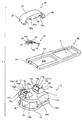
図1〜図5は本発明の代表的な第1の実施形態を示している。図1は、自動停止装置付スライドファスナー用のスライダーを構成する部品の組立て前の状態を示す斜視図であり、図2は、スライダーの一部を構成する引手保持体を裏面側から見た斜視図を示している。図3は、スライダーの組立手順を示す要部縦断面図であり、図4は、スライダーの組立後の内部構造例を示す要部縦断面図である。また、図5は、スライダーの全体斜視図を示している。Preferred embodiments of the present invention will be specifically described below with reference to the accompanying drawings.
1 to 5 show a typical first embodiment of the present invention. FIG. 1 is a perspective view showing a state before assembling parts constituting a slider for a slide fastener with an automatic stop device, and FIG. 2 is a perspective view of a handle holding body constituting a part of the slider as seen from the back side. The figure is shown. FIG. 3 is a main part longitudinal sectional view showing a procedure for assembling the slider, and FIG. 4 is a main part longitudinal sectional view showing an example of an internal structure after the slider is assembled. FIG. 5 is an overall perspective view of the slider.
尚、本実施形態では、スライダーの肩口側を前部といい、スライダーの後口側を後部という。 In the present embodiment, the shoulder side of the slider is referred to as a front part, and the rear side of the slider is referred to as a rear part.
図1に示す自動停止装置付スライドファスナー用のスライダー1は、スライダー胴体10、引手20、引手保持体30、及びスプリング体40からなる四部材によって構成されている。
A
スライダー胴体10、引手20、及び引手保持体30の三部材は、それぞれポリアミド、ポリプロピレン、ポリアセタール、ポリプチレンテレフタレートなどの熱可塑性樹脂や耐摩耗性強化材を添加した熱可塑性樹脂材料などを使って射出成形により製造される。また、スプリング体40は、銅合金やステンレス鋼などの長尺の微小な弾性金属板材が使用され、プレス加工により製造される。
The three parts of the
尚、スライダー胴体10と引手20とを熱可塑性樹脂材料を用いて製造する代わりに、アルミニウム合金、亜鉛合金などの金属材料を用いて、ダイキャスト成形によって製造しておくこともできる。そして、引手保持体30に関しても熱可塑性樹脂材料を用いて製造する代わりに、銅合金やステンレス鋼などの長尺の微小な弾性金属板材を用いて、プレス加工により製造しておくこともできる。
Instead of manufacturing the
スライダー胴体10は、上翼片11と、下翼片12と、この上下翼片11,12の前端部を連結する連結柱13とを有している。上下翼片11,12は、その後端から略中央位置にかけて、それぞれの左右側縁に上フランジ11aと下フランジ12aとを有した構成になっており、上下翼片11,12の間には、連結柱13を分岐点としたY字形の噛合エレメント案内通路が形成されている。
The
スライダー胴体10の上翼片11上面における前後部位には、前取付柱14及び後取付柱15が立設されている。前取付柱14及び後取付柱15は、細長い板状のカバー体として構成されている引手保持体30を取り付ける部材として、上翼片11の上面と一体的に成形されている。前取付柱14と後取付柱15との間には所要の間隔が形成されており、この間隔は、引手20の一部及びスプリング体40を収容するとともに、引手保持体30を収容するに十分な空間部として構成されている。
A front mounting
スライダー後口側(図1、図3及び図4の右側)に立設した後取付柱15には、左右一対の後支持壁15a,15aを備えている。一対の後支持壁15a,15aにおける外面間の横幅は、引手保持体30の外形における横幅と略同じ横幅として構成されている。一対の後支持壁15a,15aにおけるそれぞれの内面17の前端側における上部角隅部には、後述する引手保持体30に設けた第一係止部35bを係止する、切欠15cが形成されている。切欠15cは、上方及び側方が開口した段差部として構成されているとともに、引手保持体30のズレを規制する規制機構における第一被係止部として構成されている。
The
また、図1、図3、図4で示すように、一対の後支持壁15a,15aの内面17における外周縁よりも内側に下がった部位には、引手保持体30を係合させる被係合部15bが形成されている。また、内面17における外周縁周辺の部位は、引手保持体30のズレを規制する規制機構における第二被係止部17aとして構成されている。そして、第二被係止部17aにおける対向する前記外周縁周辺の部位間には、後述する引手保持体30に形成した第二係止部37bを嵌め込むことができる。
In addition, as shown in FIGS. 1, 3, and 4, the engaged members that engage the
そして、第二係止部37bが第二被係止部17a間に嵌め込まれるときには、後支持壁15aの側端面15fが、引手保持体30の裏面に当接して、引手保持体30の嵌入位置を規制する当接面として作用することになる。
When the
図3、図4で示しているように、被係合部15bは、後述する引手保持体30に形成した係合片33aを係止する部材として構成されており、滑らかに下り傾斜する案内傾斜面と、引手保持体30の係合片33aと係脱する係合面とを有する段部形状に構成されている。図1で示すように、被係合部15bは、後支持壁15aと一体的に成形されており、後支持壁15aにおける後部寄りの内面17間を連結する形で直線状に配設されている。
As shown in FIG. 3 and FIG. 4, the engaged
図1、図3、図4で示すように、後支持壁15aの前部側における対向する内面17間には、引手案内部15dが後支持壁15aと一体的に成形されており、引手案内部15dは、被係合部15bよりも低い部位に形成されている。
As shown in FIGS. 1, 3, and 4, a
引手案内部15dの前端面には、テーパ面が形成されており、このテーパー面は、後支持壁15aの前端面側における上翼片11上面に向かって下り傾斜となった引手案内面15d−1として構成されている。引手20の作動時には引手20の枢軸22を、引手案内面15d−1のテーパ面によって案内することができる。そして、引手20の枢軸22は、引手案内部15dの前部基端からスプリング体40の移動限位置に向けて、引手案内面15d−1に沿って誘導案内されることになる。
A taper surface is formed on the front end surface of the
被係合部15bにおける前部側の基端部と引手案内部15dにおける後部側の基端部との間における上翼片11の部位には、スプリング体40の爪部45が挿脱する矩形状の爪孔部15eが穿設されている。即ち、爪孔部15eは、被係合部15bにおける前部側の基端部と引手案内部15dにおける後部側の基端部との間における上翼片11の部位を、上下方向に貫通させて噛合エレメント案内通路に連通するように構成されている。
A rectangular portion into which the
スライダー肩口側(図1、図3及び図4の左側)に立設した前取付柱14には、左右一対の前支持壁14a,14aを備えている。一対の後支持壁14a,14aにおける外面間の横幅は、引手保持体30の外形に対応する横幅と略同じ横幅として構成されている。一対の後支持壁15a,15aにおけるそれぞれの内面17の前端角隅部には、後述する引手保持体30に設けた第一係止部35bを係止する、切欠14cが形成されている。切欠14cは、上方及び側方が開口した段差部として構成されているとともに、引手保持体30のズレを規制する規制機構における第一被係止部として構成されている。
The
また、一対の前支持壁14a,14aの内面16における外周縁よりも内側に下がった部位には、引手保持体30を係合させる被係合部14bと、後述するスプリング体40の開口窓部41を掛け止める突起部14dと、が形成されている。内面16における外周縁周辺の部位は、引手保持体30のズレを規制する規制機構における第二被係止部16aとして構成されている。そして、第二被係止部16aにおける対向する前記外周縁周辺の部位間には、後述する引手保持体30に形成した第二係止部37aを嵌め込むことができる。
In addition, at a portion of the
そして、第二係止部37aが第二被係止部16a間に嵌め込まれるときには、前支持壁14aの側端面14fが、引手保持体30の裏面と当接して、引手保持体30の嵌入位置を規制する当接面として作用することになる。
When the
上述したように、引手保持体30の外形形状における横幅と、一対の前支持壁14a,14aにおける外面間の横幅及び一対の後支持壁15a,15aにおける外面間の横幅とは、略同じ横幅に構成されている。これにより、引手保持体30を前取付柱14及び後取付柱15に装着することで、前支持壁14aの側端面14f及び後支持壁15aの側端面15fを、引手保持体30の裏面側によって覆い隠しておくことができる。しかも、引手保持体30の側端面と前支持壁14aの外面とを略面一の状態に構成しておくことができる。
As described above, the lateral width in the outer shape of the
図3、図4で示すように、被係合部14bは、後述する引手保持体30に形成した係合片32aを係止する部材として構成されており、滑らかに下り傾斜する案内傾斜面と、引手保持体30の係合片33aと係脱する係合面を有する段部形状に構成されている。被係合部14bは、前支持壁14aと一体的に成形されており、前支持壁14aにおける前部寄りの内面16間を連結する形で直線状に配設されている。
As shown in FIG. 3 and FIG. 4, the engaged
突起部14dは、後述するスプリング体40の開口窓部41を掛け止める部材として構成されており、前支持壁14aと一体的に成形されている。また、図3、図4で示すように、突起部14dを構成している部材と被係止部14bとの間は、下方へ窪んだ凹溝部14eとして構成され、後述するスプリング体40の掛止部44を掛け止める空間として構成されている。
The
引手20は、図1に示すように短冊状の板材によって構成されている。引手20の一端側には、把手部21が構成されるとともに、他端側には、後取付柱15を挿入できる略四角形の孔部23aを備えた環状保持部23が構成されている。環状保持部23の先端部には、円形断面をもつ枢軸22が設けられており、枢軸22は、環状保持部23の一部を構成して架橋状に構成されている。
As shown in FIG. 1, the
枢軸22の長さは、後取付柱15の幅寸法よりも大きく設定されている。引手20を装着する時には、後取付柱15を跨いだ枢軸22が引手案内部15dに沿って案内されるように移動させることで、孔部23a内に後取付柱15を挿入することができる。
The length of the
引手保持体30は、図1、図2に示すように薄肉の長尺板材により構成されており、偏平な上壁部31の前後には、上壁部31から連続した前後壁部32,33が形成されている。そして、引手保持体30は、側面形状が略横C字状となったカバー体として構成されている。
As shown in FIGS. 1 and 2, the
前後壁部32,33における各先端部の内面には、係合片32a,33aが突出して形成されている。係合片32a,33aは、前取付柱14に形成した被係合部14bの係合面と後取付柱15に形成した被係合部15bの係合面とにそれぞれ弾性的に係脱する。
引手保持体30の上壁部31における左右両側には、前取付柱14と後取付柱15との間における空間部の一部を被って遮蔽する幅広の左右翼片34が、下方に向かって突出した形状に構成されている。また、左右翼片34の下端部側における面部は、前支持壁14a及び後支持壁15aにおけるそれぞれの外側面と略面一となるように構成されている。
On the left and right sides of the
左右翼片34の両端部には、前支持壁14a及び後支持壁15aに形成した切欠14c、15cによってそれぞれ係止される第一係止部35a,35bが形成されている。第一係止部35a,35bの厚さは、左右翼片34における厚さよりも薄く構成されており、第一係止部35a,35bは、左右翼片34の内面側に配されるように構成されている。
At both ends of the left and
第一係止部35a,35bを左右翼片34の両端部に形成しておくことにより、引手保持体30の裏面と左右翼片34の端部との二面において第一係止部35a,35bを支持しておくことができるので、第一係止部35a,35bの取り付け強度を向上させておくことができる。
By forming the
尚、第一係止部35a,35bは、図2に示したように、左右翼片34の四隅に形成しておく代わりに、左右翼片34の前部側又は後部側だけ、あるいは交差する隅部だけに形成しておくこともできる。そして、第一係止部35a,35bの形成部位に対応させて、切欠14c、15cを前支持壁14a又は後支持壁15aだけ、あるいは前支持壁14aと後支持壁15aとの交差する隅部だけに形成しておくこともできる。
As shown in FIG. 2, the
即ち、第一係止部35a,35bと切欠14c、15cの配設個数としては、偶数個の組合せとして構成しておくことができ、少なくとも、スライダー1の左右方向に対して第一係止部35a又は第一係止部35bと切欠14c又は切欠15cとの組合せの組が均等に配設されるように構成しておくことが望ましい。即ち、引手保持体30に対して左右方向の外力が作用したときに、バランスよく第一係止部35a,35bと切欠14c、15cによって外力を受けることができるように、第一係止部35a,35bと切欠14c、15cとを配設しておくことが望ましい構成となる。
In other words, the number of the
図2に示すように、引手保持体30の裏面側中央部位には、スプリング体40のスプリング片42を挿入する収納凹部36が形成されている。そして、長手方向における収納凹部36を間に挟んだ引手保持体30の裏面側には、第二係止部37a,37bが突設されている。第二係止部37a,37bは、引手保持体30を前取付柱14及び後取付柱15に装着したときに、前支持壁14aの第二被係止部16a間及び後支持壁15aの第二被係止部17a間に嵌入されることになる。
As shown in FIG. 2, an
これにより、第一係止部35a,35bと第二係止部37a,37bとは、左右翼片34の両側における側端面と、引手保持体30の前後壁部32,33との間において、前後取付柱14,15の各前後支持壁14a,15aの間に配置される。そして、第一係止部35a,35bと第一係止部35a,35bが係止される切欠14c,15c、及び第二係止部37a,37bと第二係止部37a,37bが係止嵌入される第二被係止部16a,17aによって、引手保持体30のズレを規制する規制機構が構成されている。
Thereby, the
第一係止部35a,35bと第二係止部37a,37bとにおける、引手保持体30の上壁部31の裏面からの突出量に関しては、第一係止部35a,35bの突出量が第二係止部37a,37bの突出量よりも大きくなるように構成しておくことができる。このように構成しておくことで、第二係止部37a,37bの突出量を小さく構成することや、あるいは、図6に示したように、上壁部31の裏面には第二係止部37a,37bが形成されていない構成としておくことができる。
Regarding the amount of protrusion from the back surface of the
これらの場合においても、第一係止部35a,35bを前後支持壁14a,15aに形成した切欠14c、15cに係止させておくことができるので、引手保持体30に対して前後左右方向の外力が作用したとしても、引手保持体30が前後左右方向にずれてしまうのを確実に防止しておくことができる。
Even in these cases, the
しかも、第二係止部37a,37bの突出量を小さく構成しておくこと、あるいは、上壁部31の裏面には第二係止部37a,37bが形成されていない構成にしておくことで、引手保持体30における可撓性及び弾性力を高めておくことができる。即ち、引手保持体30を前後取付柱14,15に係合させるときに、引手保持体30を弾性変形させながら引手保持体30の両端部間を拡開させるのを容易に行うことができる。しかも、引手保持体30における可撓性を高めておくことができるので、引手保持体30の両端部間を拡開させる弾性変形中に、引手保持体が破損したりするのを防止できる。
Moreover, the amount of protrusion of the
スプリング体40は、銅合金やステンレス鋼などの板材からなる本体と、本体の長さ方向の一端側に形成した矩形の開口窓部41とを有した構成となっている。そして、スプリング体40には、スプリング片42が設けられており、スプリング片42は、開口窓部41の本体側端部からスプリング体40の長手方向における中央部を切抜孔43によって外形抜きを行い、外形抜き部を抜き起こした構成となっている。
The
そして、曲げ加工されたスプリング片42の先端部が、所定の高さとなるようにスプリング片42の基端部から前方に向けてく字状に張り出した形状に起こされている。スプリング片42の先端部側には、曲げ加工が施されておりスプリング片42の先端部が偏平状となるように構成されている。
The distal end portion of the
また、スプリング片42の先端部側における両側面部は、図1に示すように、スライダー肩口方向の先端に向けて漸次縮小するテーパ面42aとして形成されている。そして、偏平状のスプリング片42の先端部は、引手保持体30の裏面に形成した収納凹部36に収納されることで、スプリング片42の左右方向へのズレを防止している。
Further, as shown in FIG. 1, both side surface portions on the distal end side of the
スプリング体40の前後方向における両端部には、それぞれスプリング片42とは反対面側の下方に向かって屈曲した短尺板片と長尺板片とが略平行に形成されている。短尺板片には、前取付柱14の凹溝部14eに掛け止めされる掛止部44が構成されており、長尺板片の先端部には、爪部45が構成されている。
At both ends in the front-rear direction of the
爪部45の先端は、スプリング体40の本体部における幅寸法よりも幅狭に形成されている。そして、爪部45が、後取付柱15に形成した爪孔部15eを通って、スライダー胴体10における噛合エレメント案内通路内にまで挿脱可能となるように、爪部45の先端における形状は、所要の大きさで所要の形態となるように構成されている。
The tip of the
また、短尺板片の屈曲部に穿設された開口窓部41には、前取付柱14に設けた突片部14dを挿入させることができる。このように構成されたスプリング体40の全体構成は、スプリング片42を除いて考えると側面視において略横C字状に構成されている。
Further, the projecting
スプリング片42を外形抜き加工によって形成することができるので、スプリング体40としては、必要最小限の寸法を備えた前記板材から製造することができる。このため、スプリング体40を製造するのに要する前記板材の使用量を節約することができ、しかも、スプリング体40の構成は、上述したように簡単な構成にすることができるので、スプリング体40を製造するときの歩留り率を向上させることができる。
Since the
尚、スプリング片42の先端は、引手保持体30の裏面に形成した収納凹部36内で摺接しながら弾接するように構成されているので、収納凹部36における長手方向の寸法としては、スプリング片42の先端の摺接を許容する寸法に形成されている。
Since the tip of the
また、スプリング片42の先端部と、スプリング片42を抜き起こした後のスプリング片42の立上り側稜線部と、の間には平面方向の空隙が形成されている。この平面方向の空隙を形成しておくことによって、スプリング片42が弾性変形を行う時に、スプリング片42が切抜孔43内に嵌入したとしても、切抜孔43とスプリング片42とが引っ掛かってしまうことなく、スプリング片42は元の状態に円滑に且つ確実に弾性復帰することができる。これによって、スライダー1の自動停止機能は、長期間に亘って安定した状態を確保しておくことができる。
A space in the plane direction is formed between the tip of the
このように構成されているスプリング体40の製造について説明を行う。先ず、スプリング体40を構成する板材からスプリング片42の前端面に隣接する部位を予め打抜き、開口窓部41となる打抜孔を形成する。また、爪部45となる形成部の一部を前記板材から打抜いて切断しておく。
The manufacture of the
次に、スプリング片42の先端が開口窓部41となるようにして、スプリング片42の先端に向けて漸次縮小する外郭形態に沿う左右両側端縁を打抜パンチにより打抜加工する。この打抜加工後に、スプリング片42に対して曲げ加工を施し、スプリング片42の先端が所定の高さとなるようして、略く字状に抜き起こしを行なう。そして、開口窓部41を有したスプリング体40の全体構成が、略横C字状の形態となるように仕上げる。
Next, the left and right side edges along the outer shape gradually shrinking toward the tip of the
このようにして構成されたスプリング体40は、開口窓部41を設けておくことができるので、開口窓部41を介してスプリング片42を抜き起こすことが容易になる。しかも、前記板材に対するスプリング片42の所要な打抜き高さを得ることができ、加工中にスプリング片42の先端部に過度の力が加えられて切損又は亀裂が生じたりすることを防止できる。そして、所望のバネ剛性をもったスプリング体40を容易に且つ確実に製造することができる。
Since the
このように、スプリング体40を簡単に製造することができるので、特別な各種の付帯設備や周辺装置を必要とすることなく、既存の加工装置を用いてスプリング体40を製造することができる。従って、生産性を向上させることができ、処理コストも安くなり、また、スプリング体40の製造時間も短縮することができるので、製作費などを大幅に低減することができる。
As described above, since the
尚、スプリング片42の構成として、スプリング片42の全体が前方に向けて略く字状に張り出した形態をなしている構成例を説明したが、本発明はこれに限定されるものではなく、例えば、スプリング片42に対して曲げ加工を施して、スプリング片42を下方に向けて一回以上屈曲させた構成により、スプリング片42の先端部が所定の高さ位置となるように抜き起こした構成にしておくこともできる。
In addition, as a configuration of the
次に、スライダー1を組み立てて図5に示したように構成する組立て手順について説明する。
Next, an assembling procedure for assembling the
スライダー1を組み立てるには、図3で示すように、先ず、引手20の環状保持部23(図1参照)の孔部23aをスライダー胴体10の後取付柱15を跨いで挿入する。そして、引手20の枢軸22を、後支持壁15a(図1参照)の引手案内部15dの引手案内面15d−1に当接させた状態で、引手20全体が略水平姿勢となるようにスライダー胴体10上に載置する。
In order to assemble the
次いで、引手20の枢軸22の上方からスプリング体40を配置する。このとき、スプリング体40の爪部45を後取付柱15の爪孔部15eに挿入し、開口窓部41を爪孔部15eよりも高位にある前取付柱14の突片部14dに掛止める。同時に、掛止部44を前取付柱14の凹溝部14e内に挿入する。
Next, the
このとき、スプリング体40は、上翼片11の上面において爪孔部15eから突片部14d側に向けて上り傾斜した状態で配されることになる。次に、スプリング片42の弾力に抗しながら、引手保持体30を、スプリング体40の上方から前後取付柱14,15に装着させる。
At this time, the
引手保持体30を前後取付柱14,15に装着させるときには、引手保持体30の係合片32a,33aは、前後取付柱14,15の被係合部14b,15bの案内傾斜面に沿って拡開方向に弾性変形しながら摺動する。係合片32a,33a が案内傾斜面の先端傾斜面を通過すると同時に、係合片32a,33aは縮小方向に弾性復帰して、被係合部14b,15bの係合面に係合することになる。
When the
このとき同時に、第一係止部35a,35bは、切欠14c、15cに係止され、第二係止部37a,37bは、第二被係止部16a,17a間に嵌入されることになる。また、引手保持体30の左右翼片34の下端面は、上翼片11の上面から離間した位置に配されるとともに、左右翼片34によって引手20の一部及びスプリング体40を操作する操作空間部の一部を遮蔽する。こうして、スライダー1の組立てが完了する。
At the same time, the
本発明は、引手保持体30の係合片32a,33aと前後取付柱14,15の被係合部14b,15bとを係合させて固定させるといった簡単な構造でありながら、引手保持体30をスライダー胴体10に装着させるだけで、スプリング体40を開離不能に引手保持体30とスライダー胴体10との間に収納しておくことができる。
Although the present invention has a simple structure in which the engaging
しかも、スライダー1の組立て作業は、人手又は自動組立て機によって、容易に且つ安定した状態で確実に行うことができる。また、引手保持体30が前後左右方向にガタついてしまうのを、規制機構によって防止しておくことができる。また、引手保持体30の裏面と前後取付柱14,15の対向面間とによって形成された空間内で、スプリング片42を円滑に且つ確実に弾性変形させることができる。しかも、スプリング片42の破損、不良変形、故障などを防止しておくことができるので、長期間にわたってスプリング体40の耐久性を確保しておくことができる。
Moreover, the assembling work of the
図4の状態からスプリング体40の爪部45と、図示せぬ噛合エレメントとの係合状態を解除する操作について説明する。先ず、図4に示すようにスライダー胴体10に対して平行に組み立てられた引手20を手で上方へ持ち上げると、あるいは、引手20を後方へ引っ張ると、引手20の枢軸22は引手案内部15dの引手案内面15d−1に沿って上昇する。
The operation for releasing the engagement state between the
引手20の枢軸22が上昇するに伴い、スプリング体40も上方に持ち上げられてスプリング片42は、弾性力が貯えられる方向に撓んでゆく。そして、スプリング体40の爪部45は、図示せぬ噛合エレメントとの係合状態が解除される方向に弾性変形しながら、引手20の枢軸22を中心として前方に向けて揺動する。
As the
引手20の枢軸22が、左右翼片34の下端面に当接して、スプリング体40の移動限位置まで移動すると、爪部45は、今まで係合していた噛合エレメントから離れることになり、爪部45と噛合エレメントとの係合状態が解除される。
When the
この爪部45と噛合エレメントとの係合状態の解除時に、スライダー1は、スライダー肩口側(図4の左側)或いは後口側(図4の右側)へと自由に摺動することができる。スライダー1を自由に摺動させることにより、図示せぬファスナーチェーンの務歯列を噛合させたり、左右に開離させたりすることができる。この所望の操作後に、引手20を手放すと、スプリング体40のスプリング片42は弾性復帰を行う。
When the engagement state between the
スプリング片42の弾性復帰に伴う付勢力によって、引手20の枢軸22は引手案内面15d−1に沿って下降する。そして、スプリング体40の爪部45もスプリング片42の付勢力によって、爪孔部15e内に挿入され、爪孔部15eの下方部に存在するファスナーチェーンの務歯間に対して自動的に挿入される。このように、スプリング片42の付勢力によって、スプリング体40の爪部45と噛合エレメントとは係合されることになる。
Due to the urging force accompanying the elastic return of the
スプリング体40による付勢力によって、爪部45と噛合エレメントとの係合状態が維持されていると、それ以上のスライダー1の摺動が阻止されて、スライダー1の停止状態を維持しておくことができる。
When the engagement state between the
また、本発明のスライダー1では、引手保持体30の前後左右方向へのガタツキを防止するため、第一係止部35a,35b及び切欠14c、15cと第二係止部37a,37b及び第二被係止部16a,17aとによって構成された規制機構を採用している。
尚、規制機構としては、第一係止部35a,35b及び切欠14c、15cによる規制構成又は第二係止部37a,37b及び第二被係止部16a,17aによる規制構成のうちで、一方の規制構成だけを用いて構成しておくこともできる。Further, in the
As the restriction mechanism, one of the restriction configuration by the
この規制機構を採用することによって、前取付柱14の前支持壁14aにおける側端面14f及び後取付柱15の後支持壁15aにおける側端面15fを、前取付柱14及び後取付柱15に取り付けた引手保持体30によって覆い隠しておくことができる。
By adopting this restriction mechanism, the
しかもこのとき、引手保持体30の側端面及び左右翼片34の外側面と前支持壁14a及び後支持壁15aの外面とは、略面一の関係に配設される構成となるので、スライダー1における外観意匠性を大幅に向上させることができる。
In addition, at this time, the side end surface of the
このように規制機構によって、引手保持体30が前後及び幅方向のあらゆる力に対してぐらつくことがない状態で、強固に且つ確実に引手保持体30を前取付柱14及び後取付柱15に装着しておくことができる。これによって、引手保持体30を必要最小限の肉厚に形成することができるとともに、スライダー1の小型化や薄型化を達成することができる。
In this way, the
本発明の左右翼片34は、前取付柱14と後取付柱15との間隔と略同じ長さに形成されているが、左右翼片34の上下方向の長さ寸法は、前壁部32及び後壁部33の上下方向の高さ寸法よりも短く構成されている。このように構成しておくことによって、スライダー胴体10と引手保持体30とが係合状態にあるときには、左右翼片34の下端面位置が上翼片11の上面から上方に離れた位置にしておくことができる。
The left and
そして、左右翼片34の下端面と上翼片11の上面との間に、引手20の枢軸22が動き得る空間部を形成しておくことができる。引手保持体30の裏面と上翼片11の上面とによって囲まれる空間は、スライダー胴体10と引手保持体30とが係合状態にあるときには、引手20の枢軸22及びスプリング体40を操作するときの操作空間部とすることができる。
A space in which the
しかも、引手保持体30と上翼片11との間に、スプリング体40のスプリング片42を円滑に且つ確実に保持しておくことができるようになるので、スライダー1の品質を長期間にわたり安定した状態に確保しておくことができる。
Moreover, since the
このように、本発明では、スライダー1を小型化や薄型化させることができ、しかも、外観意匠性に優れたものとして構成することができるので、商品価値の高いスライダーを得ることができる。
As described above, according to the present invention, the
図7及び図8は、本発明に係る規制機構の変形例を示している。図7は、引手保持体を裏面側から見た斜視図を示しており、図8は、実施例2の引手保持体を用いた自動停止装置付スライドファスナー用のスライダーを構成する部品を組み立てる前の状態を示す斜視図である。 7 and 8 show modifications of the restriction mechanism according to the present invention. FIG. 7 shows a perspective view of the handle holding body as viewed from the back side, and FIG. 8 shows a state before assembling the parts constituting the slider for the slide fastener with automatic stop device using the handle holding body of the second embodiment. It is a perspective view which shows the state of.
実施例1における規制機構の一つとして、第一係止部35a,35bを左右翼片24の両端部に形成し、第一係止部35a,35bをそれぞれ係止される切欠14c,15cを前支持壁14a及び後支持壁15aの隅部に形成した構成を採用している。これに対して、実施例2では、第一係止部35a,35bと切欠14c,15cとを設ける代わりに、左右翼片24の両端部から離間した部位に設けた突起係止片39と、前支持壁14aの側端面14f及び後支持壁15aの側端面15fとに穿設した被係止穴部19と、による構成を採用している。
As one of the restricting mechanisms in the first embodiment,
そして、突起係止片39を被係止穴部19内に挿入することで、規制機構の一つを構成している。また、実施例1における他の規制機構である、第二係止部37a,37bと前支持壁14aの内面16及び後支持壁15aの内面17とによる規制機構は、実施例1における構成を実施例2においてもそのまま採用している。
Then, the
実施例2における他の構成は、実施例1と同様の構成を備えている。そこで、実施例1と同様の構成を備えている部材に関しては、実施例1で用いた部材符号と同じ部材符号を用いることで、その部材に関する説明を省略する。 Other configurations in the second embodiment are the same as those in the first embodiment. Therefore, for members having the same configuration as that of the first embodiment, the same member codes as those used in the first embodiment are used, and the description of the members is omitted.
図7に示すように、引手保持体30の裏面側における左右翼片24の両端部から離間した部位には、引手保持体30の裏面から立設し、左右翼片34とは独立した突起係止片39がそれぞれ形成されている。また、図8に示すように、前取付柱14における一対の前支持壁14aの側端面14f及び後取付柱15における一対の後支持壁15aの側端面15fには、引手保持体30を前取付柱14と後取付柱15とに装着するときに、引手保持体30の各突起係止片39を挿入して係止する被係止穴部19が形成されている。
As shown in FIG. 7, in a portion spaced from both ends of the left and right wing pieces 24 on the back surface side of the
突起係止片39及び被係止穴部19の配設個数としては、偶数個としておくことができ、少なくとも、スライダー1の左右方向に均等に配設しておくことが、望ましい構成となる。即ち、引手保持体30に対して左右方向の外力が作用したときに、バランスよく突起係止片39及び被係止穴部19で外力を受けることができるように、突起係止片39及び被係止穴部19を配設しておくことが望ましい構成となる。
The number of the
被係止穴部19の構成としては、上方を開口させた穴形状に構成しておく場合以外にも、前支持壁14aの内面16f及び後支持壁15aの内面17側に開口した溝形状に構成しておくこともできる。
As the configuration of the locked
規制機構の一つとして、突起係止片39及び被係止穴部19の構成を用いることにより、各被係止穴部19に挿入した突起係止片39において、引手保持体30が前後左右方向にずれてしまうのを防止でき、引手保持体30のズレを確実に防止できる。しかも、被係止穴部19に挿入した少なくとも1つの突起係止片39だけによっても、引手保持体30が前後左右方向にずれるのを規制しておくことができる。このため、突起係止片39の配設個数を少なく構成しておくこともできる。
As one of the restricting mechanisms, by using the configuration of the
上述した各実施例は、本発明の好適な実施形態を例示したものである。しかし、規制機構の構成は、上述した構成だけに限定されるものではなく、例えば、前支持壁14aの側端面14f及び後支持壁15aの側端面15fに沿って凸条の突起を形成し、この突起が嵌入する凹条の溝を引手保持体30の裏面に形成しておくこともできる。
Each example mentioned above illustrates a preferred embodiment of the present invention. However, the configuration of the restricting mechanism is not limited to the above-described configuration.For example, a protruding protrusion is formed along the
このように規制機構を構成にしても、本発明の目的を充分に達成することができることは勿論である。従って、本発明は上記各実施例に限定されないことは当然であり、各請求の範囲に記載した範囲内において様々な形態に設計変更することが可能である。 Of course, even if the restriction mechanism is configured as described above, the object of the present invention can be sufficiently achieved. Accordingly, the present invention is naturally not limited to the above-described embodiments, and can be modified in various forms within the scope described in the claims.
本発明は、自動停止装置付のスライダー以外であっても、引手保持体を備えたスライダーに対して好適に適用することができる。 The present invention can be suitably applied to a slider provided with a handle holder even if it is not a slider with an automatic stop device.
Claims (4)
前記スプリング体40は、前記引手保持体30の裏面と前記引手20との間に弾接して配されるスプリング片42と、前記引手20の操作による前記スプリング片42の弾性変形に基づいて、前記スライダー胴体10の内部に通した前記ファスナーチェーンの務歯列の一部との係合及び係合解除を行う爪部45と、を有し、
前記スライダー胴体10上面の前後には、それぞれ被係合部14b,15bが形成された前取付柱14及び後取付柱15が設けられ、
前記引手保持体30は、偏平な上壁部31の前後に形成された前後壁部32,33を有する側面視が略横C字状のカバー体として構成され、
前記前後壁部32,33の各先端部内面には、前記被係合部14b,15bと弾性的に係合する係合片32a,33aが形成されてなる自動停止装置付スライドファスナー用スライダー1において、
前記スライダー1の左右幅方向において、前記引手保持体30の幅寸法と、前記前取付柱14及び後取付柱15の幅寸法とは、略等しい幅寸法に構成され、
前記引手保持体30は、前記引手保持体30の上壁部31の左右両側から下方に突出し、前記前取付柱14と前記後取付柱15との間の空間部を被って遮蔽する左右翼片34を有し、
前記前取付柱14及び前記後取付柱15は、それぞれ前記前取付柱14及び後取付柱15の左右端面に立設した支持壁14a,15aを有し、
前記引手保持体30と、前記前取付柱14及び前記後取付柱15のうち少なくとも一方の取付柱14,15との間には、前記引手保持体30の上壁部31が左右方向に移動するのを規制する規制機構35a,35b,15c、37a,37b,16a,17a、39,19が設けられ、
前記規制機構35a,35b,15c、37a,37b,16a,17a、39,19は、前記スライダー1の左右幅方向における前記左右翼片34の内面側であって、前記左右翼片34の側端面と前記前後壁部32,33との間において、前記上壁部31の裏面から下方に向かって突出した形状に構成されてなる係止部35a,35b、37a,37b、39と、前記スライダー1の左右幅方向における前記支持壁14a,15aの内面16,17側において、前記係止部35a,35b、37a,37b、39を収納する形状に構成されてなる被係止部15c、16a,17a、19と、から構成され、
前記引手保持体30の前記各係合片32a,33aを、それぞれ前記前取付柱14の被係合部14b及び前記後取付柱15の被係合部15bに係合させたとき、前記係止部35a,35b、37a,37b、39と前記被係止部15c、16a,17a、19とは互いに係止状態となり、かつ前記引手保持体30は、前記前取付柱14及び後取付柱15の側端面14f,15fを覆い隠す状態に配されてなることを特徴とする自動停止装置付スライドファスナー用スライダー。Between the slider body 10 that engages and separates the dentition of the fastener chain, the pull 20 that slides the slider body 10, and the upper part of the slider body 10 is mounted and supported, and between the upper surface of the slider body 10 A puller holding body 30 for holding the puller 20 movably, and a spring body 40 disposed between the back surface of the puller holding body 30 and the slider body 10,
The spring body 40 is based on the spring piece 42 arranged in elastic contact between the back surface of the pull handle holder 30 and the pull handle 20, and the elastic deformation of the spring piece 42 by the operation of the pull handle 20. A claw portion 45 that engages and disengages with a part of the dentition of the fastener chain that has passed through the inside of the slider body 10, and
Before and after the upper surface of the slider body 10, there are provided a front mounting column 14 and a rear mounting column 15 formed with engaged portions 14b and 15b, respectively.
The handle holder 30 is configured as a substantially horizontal C-shaped cover body having front and rear wall portions 32, 33 formed before and after the flat upper wall portion 31,
Slider 1 for slide fastener with automatic stop device in which engagement pieces 32a and 33a that elastically engage with the engaged portions 14b and 15b are formed on the inner surfaces of the front and rear wall portions 32 and 33, respectively. In
In the left-right width direction of the slider 1, the width dimension of the handle holder 30 and the width dimensions of the front mounting column 14 and the rear mounting column 15 are configured to be substantially equal width dimensions,
The handle holder 30 protrudes downward from the left and right sides of the upper wall portion 31 of the handle holder 30 and covers the space between the front mounting column 14 and the rear mounting column 15 to shield the left and right wing pieces. 34,
The front mounting column 14 and the rear mounting column 15 have support walls 14a and 15a erected on the left and right end surfaces of the front mounting column 14 and the rear mounting column 15, respectively.
An upper wall portion 31 of the pull holder 30 moves in the left-right direction between the pull holder 30 and at least one of the front and rear mounting columns 14 and 15. Regulation mechanisms 35a, 35b, 15c, 37a, 37b, 16a, 17a, 39, 19 are provided,
The regulation mechanisms 35a, 35b, 15c, 37a, 37b, 16a, 17a, 39, 19 are on the inner surface side of the left and right wing pieces 34 in the left and right width direction of the slider 1, and are side end surfaces of the left and right wing pieces 34. Engaging portions 35a, 35b, 37a, 37b, 39 configured to protrude downward from the back surface of the upper wall portion 31 between the front and rear wall portions 32, 33, and the slider 1. Locked portions 15c, 16a, 17a configured to accommodate the lock portions 35a, 35b, 37a, 37b, 39 on the inner surface 16, 17 side of the support walls 14a, 15a in the left-right width direction. , 19 and
When the engaging pieces 32a and 33a of the pull handle holder 30 are engaged with the engaged portion 14b of the front mounting column 14 and the engaged portion 15b of the rear mounting column 15, respectively, The portions 35a, 35b, 37a, 37b, 39 and the locked portions 15c, 16a, 17a, 19 are locked with each other, and the handle holding body 30 is formed of the front mounting column 14 and the rear mounting column 15. A slide fastener slider with an automatic stop device, characterized in that it is arranged so as to cover the side end faces 14f, 15f.
前記引手保持体30の前記各係合片32a,33aを、それぞれ前記前取付柱14の被係合部14b及び前記後取付柱15の被係合部15bに係合させたときに、前記支持壁14a,15aの内面16,17間に嵌入する第二係止部37a,37bと、を有し、
前記被係止部15c、16a,17aは、前記第一係止部35a,35bを係合させ、前記支持壁14a,15aの内面16,17における前記前支持壁14aと前記後支持壁15aとが対峙する上部角隅部において、上方と側方とを開口した段差部15cと、前記支持壁14a,15aの内面16,17における外周縁側の部位16a,17aと、を有してなることを特徴とする請求項1に記載の自動停止装置付スライドファスナー用スライダー。The locking portions 35a, 35b, 37a, 37b are first locking portions 35a, 35b configured in a shape extending from the left and right wing pieces 34 toward the front and rear wall portions 32, 33, and
When the engaging pieces 32a and 33a of the pull handle holder 30 are engaged with the engaged portion 14b of the front mounting column 14 and the engaged portion 15b of the rear mounting column 15, respectively, the support Second locking portions 37a, 37b fitted between the inner surfaces 16, 17 of the walls 14a, 15a,
The locked portions 15c, 16a, 17a engage the first locking portions 35a, 35b, and the front support wall 14a and the rear support wall 15a on the inner surfaces 16, 17 of the support walls 14a, 15a At the upper corners facing each other, there are stepped portions 15c that open upward and laterally, and outer peripheral side portions 16a, 17a on the inner surfaces 16, 17 of the support walls 14a, 15a. The slider for a slide fastener with an automatic stop device according to claim 1 , wherein the slider is a slide fastener.
Applications Claiming Priority (1)
| Application Number | Priority Date | Filing Date | Title |
|---|---|---|---|
| PCT/JP2008/058347 WO2009133617A1 (en) | 2008-05-01 | 2008-05-01 | Slider for slide fastener with automatic stopper |
Publications (2)
| Publication Number | Publication Date |
|---|---|
| JPWO2009133617A1 JPWO2009133617A1 (en) | 2011-08-25 |
| JP5106629B2 true JP5106629B2 (en) | 2012-12-26 |
Family
ID=41254847
Family Applications (1)
| Application Number | Title | Priority Date | Filing Date |
|---|---|---|---|
| JP2010509977A Active JP5106629B2 (en) | 2008-05-01 | 2008-05-01 | Slider for slide fastener with automatic stop device |
Country Status (9)
| Country | Link |
|---|---|
| US (1) | US8356391B2 (en) |
| EP (1) | EP2286687B1 (en) |
| JP (1) | JP5106629B2 (en) |
| KR (1) | KR101245498B1 (en) |
| CN (1) | CN102014686B (en) |
| ES (1) | ES2427728T3 (en) |
| HK (1) | HK1154466A1 (en) |
| TW (1) | TW201012410A (en) |
| WO (1) | WO2009133617A1 (en) |
Families Citing this family (14)
| Publication number | Priority date | Publication date | Assignee | Title |
|---|---|---|---|---|
| US9003614B2 (en) * | 2010-04-02 | 2015-04-14 | Ykk Corporation | Slider for slide fastener |
| US8453301B1 (en) * | 2010-07-22 | 2013-06-04 | Patty McCoy | Zipper pull tab retention device |
| EP2689682B1 (en) * | 2011-03-24 | 2017-03-08 | YKK Corporation | Slide fastener and slider with simple locking mechanism |
| EP2737817A4 (en) * | 2011-07-28 | 2015-03-11 | Ykk Corp | Slider for slide fastener |
| US10194719B2 (en) * | 2012-08-04 | 2019-02-05 | Kee (Guangdong) Garment Accessories Limited | Enhanced slider |
| EP2878221A1 (en) * | 2012-08-04 | 2015-06-03 | Kee (Guangdong) Garment Accessories Ltd | Automactic locking slider |
| WO2014080532A1 (en) * | 2012-11-26 | 2014-05-30 | Ykk株式会社 | Slide fastener slider |
| CN104976144B (en) * | 2014-04-14 | 2017-10-10 | 佛山市建准电子有限公司 | Fan and its motor protective cover |
| TWM512945U (en) * | 2015-07-03 | 2015-12-01 | Lung Chou Ind Co Ltd | Zipper head structure |
| US10064456B2 (en) * | 2015-07-03 | 2018-09-04 | Chung Chwan Enterprise Co., Ltd. | Zip slider structure |
| US10098421B2 (en) * | 2015-11-30 | 2018-10-16 | Chung Chwan Enterprise Co., Ltd. | Zipper head assembly structure and sliding member thereof |
| TWI679948B (en) * | 2017-08-07 | 2019-12-21 | 中傳企業股份有限公司 | Zipper head assembly structure and elastic element thereof |
| PT3871553T (en) * | 2020-02-28 | 2023-01-02 | Riri Sa | Slider for a slide fastener |
| US20230210227A1 (en) | 2020-06-08 | 2023-07-06 | Ykk Corporation | Slider |
Citations (3)
| Publication number | Priority date | Publication date | Assignee | Title |
|---|---|---|---|---|
| JPS58100611U (en) * | 1981-12-28 | 1983-07-08 | ワイケイケイ株式会社 | Slider with automatic stop device for slide fasteners |
| US6654988B1 (en) * | 2002-11-26 | 2003-12-02 | Roger C. Y. Chung | Stoppable zipper slider capable of being reassembled with pull tab |
| JP2004344313A (en) * | 2003-05-21 | 2004-12-09 | Ykk Corp | Spring body for sliding fastener and slider equipped with spring body |
Family Cites Families (7)
| Publication number | Priority date | Publication date | Assignee | Title |
|---|---|---|---|---|
| JPS58100611A (en) | 1981-12-11 | 1983-06-15 | Sumitomo Metal Ind Ltd | Decreasing method of nitrogen component in gas generator |
| JP3393572B2 (en) * | 1996-04-30 | 2003-04-07 | ワイケイケイ株式会社 | Slider for slide fastener with automatic stop device and cover molding die for the slider |
| JP3369059B2 (en) | 1996-09-30 | 2003-01-20 | ワイケイケイ株式会社 | Slider for slide fastener with automatic stop device |
| JPH10127313A (en) | 1996-10-31 | 1998-05-19 | Ykk Corp | Slider for sliding fastener with automatic stopping device |
| JP3935819B2 (en) | 2002-10-29 | 2007-06-27 | Ykk株式会社 | Slider for slide fastener with automatic stop device |
| JP4152254B2 (en) * | 2003-05-21 | 2008-09-17 | Ykk株式会社 | Slider for slide fastener |
| CN2719076Y (en) * | 2004-08-18 | 2005-08-24 | 刘炼 | Zipper head |
-
2008
- 2008-05-01 WO PCT/JP2008/058347 patent/WO2009133617A1/en active Application Filing
- 2008-05-01 KR KR1020107024322A patent/KR101245498B1/en active IP Right Grant
- 2008-05-01 EP EP08752277.7A patent/EP2286687B1/en active Active
- 2008-05-01 CN CN200880128976XA patent/CN102014686B/en active Active
- 2008-05-01 US US12/990,325 patent/US8356391B2/en active Active
- 2008-05-01 JP JP2010509977A patent/JP5106629B2/en active Active
- 2008-05-01 ES ES08752277T patent/ES2427728T3/en active Active
-
2009
- 2009-04-24 TW TW098113658A patent/TW201012410A/en unknown
-
2011
- 2011-08-17 HK HK11108679.8A patent/HK1154466A1/en not_active IP Right Cessation
Patent Citations (3)
| Publication number | Priority date | Publication date | Assignee | Title |
|---|---|---|---|---|
| JPS58100611U (en) * | 1981-12-28 | 1983-07-08 | ワイケイケイ株式会社 | Slider with automatic stop device for slide fasteners |
| US6654988B1 (en) * | 2002-11-26 | 2003-12-02 | Roger C. Y. Chung | Stoppable zipper slider capable of being reassembled with pull tab |
| JP2004344313A (en) * | 2003-05-21 | 2004-12-09 | Ykk Corp | Spring body for sliding fastener and slider equipped with spring body |
Also Published As
| Publication number | Publication date |
|---|---|
| TWI376211B (en) | 2012-11-11 |
| JPWO2009133617A1 (en) | 2011-08-25 |
| EP2286687A1 (en) | 2011-02-23 |
| HK1154466A1 (en) | 2012-04-27 |
| EP2286687A4 (en) | 2012-04-25 |
| ES2427728T3 (en) | 2013-10-31 |
| WO2009133617A1 (en) | 2009-11-05 |
| EP2286687B1 (en) | 2013-07-17 |
| KR20100128347A (en) | 2010-12-07 |
| CN102014686B (en) | 2012-03-21 |
| KR101245498B1 (en) | 2013-03-25 |
| CN102014686A (en) | 2011-04-13 |
| TW201012410A (en) | 2010-04-01 |
| US8356391B2 (en) | 2013-01-22 |
| US20110041297A1 (en) | 2011-02-24 |
Similar Documents
| Publication | Publication Date | Title |
|---|---|---|
| JP5106629B2 (en) | Slider for slide fastener with automatic stop device | |
| JP5501252B2 (en) | Slider for slide fastener | |
| TWI516220B (en) | Zipper pull with the back of the slider | |
| JP4152254B2 (en) | Slider for slide fastener | |
| JP4149369B2 (en) | Slider for slide fastener with automatic stop device | |
| JP5562412B2 (en) | Slider for slide fastener | |
| JP5274662B2 (en) | Slide fastener | |
| JP3927922B2 (en) | Slide body for slide fastener and slider equipped with the spring body | |
| JP5957091B2 (en) | Slider for slide fastener | |
| US20130185904A1 (en) | Slider for Slide Fastener | |
| TWI528913B (en) | Zipper with slider | |
| EP2737817A1 (en) | Slider for slide fastener | |
| JP5496301B2 (en) | Slider for slide fastener | |
| WO2012042602A1 (en) | Openable retainer for slide fasteners | |
| CN110536622B (en) | Slider for slide fastener | |
| EP4162834A1 (en) | Slider | |
| JP2013006083A (en) | Slider for slide fastener | |
| WO2016147262A1 (en) | Slider and slide fastener | |
| JP5844386B2 (en) | Slider with stop mechanism | |
| EP3009026B1 (en) | Slider for slide fastener | |
| WO2013001597A1 (en) | Slider for slide fasteners |
Legal Events
| Date | Code | Title | Description |
|---|---|---|---|
| A131 | Notification of reasons for refusal |
Free format text: JAPANESE INTERMEDIATE CODE: A131 Effective date: 20120710 |
|
| A521 | Written amendment |
Free format text: JAPANESE INTERMEDIATE CODE: A523 Effective date: 20120830 |
|
| TRDD | Decision of grant or rejection written | ||
| A01 | Written decision to grant a patent or to grant a registration (utility model) |
Free format text: JAPANESE INTERMEDIATE CODE: A01 Effective date: 20121002 |
|
| A01 | Written decision to grant a patent or to grant a registration (utility model) |
Free format text: JAPANESE INTERMEDIATE CODE: A01 |
|
| A61 | First payment of annual fees (during grant procedure) |
Free format text: JAPANESE INTERMEDIATE CODE: A61 Effective date: 20121002 |
|
| R150 | Certificate of patent or registration of utility model |
Ref document number: 5106629 Country of ref document: JP Free format text: JAPANESE INTERMEDIATE CODE: R150 Free format text: JAPANESE INTERMEDIATE CODE: R150 |
|
| FPAY | Renewal fee payment (event date is renewal date of database) |
Free format text: PAYMENT UNTIL: 20151012 Year of fee payment: 3 |