JP5106383B2 - Audio encoding and decoding - Google Patents
Audio encoding and decoding Download PDFInfo
- Publication number
- JP5106383B2 JP5106383B2 JP2008503634A JP2008503634A JP5106383B2 JP 5106383 B2 JP5106383 B2 JP 5106383B2 JP 2008503634 A JP2008503634 A JP 2008503634A JP 2008503634 A JP2008503634 A JP 2008503634A JP 5106383 B2 JP5106383 B2 JP 5106383B2
- Authority
- JP
- Japan
- Prior art keywords
- data
- signal
- mix
- channel
- reinforcement
- Prior art date
- Legal status (The legal status is an assumption and is not a legal conclusion. Google has not performed a legal analysis and makes no representation as to the accuracy of the status listed.)
- Active
Links
Images


Classifications
-
- G—PHYSICS
- G10—MUSICAL INSTRUMENTS; ACOUSTICS
- G10L—SPEECH ANALYSIS OR SYNTHESIS; SPEECH RECOGNITION; SPEECH OR VOICE PROCESSING; SPEECH OR AUDIO CODING OR DECODING
- G10L19/00—Speech or audio signals analysis-synthesis techniques for redundancy reduction, e.g. in vocoders; Coding or decoding of speech or audio signals, using source filter models or psychoacoustic analysis
- G10L19/008—Multichannel audio signal coding or decoding using interchannel correlation to reduce redundancy, e.g. joint-stereo, intensity-coding or matrixing
-
- H—ELECTRICITY
- H03—ELECTRONIC CIRCUITRY
- H03M—CODING; DECODING; CODE CONVERSION IN GENERAL
- H03M7/00—Conversion of a code where information is represented by a given sequence or number of digits to a code where the same, similar or subset of information is represented by a different sequence or number of digits
- H03M7/30—Compression; Expansion; Suppression of unnecessary data, e.g. redundancy reduction
-
- H—ELECTRICITY
- H04—ELECTRIC COMMUNICATION TECHNIQUE
- H04S—STEREOPHONIC SYSTEMS
- H04S3/00—Systems employing more than two channels, e.g. quadraphonic
-
- H—ELECTRICITY
- H04—ELECTRIC COMMUNICATION TECHNIQUE
- H04S—STEREOPHONIC SYSTEMS
- H04S3/00—Systems employing more than two channels, e.g. quadraphonic
- H04S3/008—Systems employing more than two channels, e.g. quadraphonic in which the audio signals are in digital form, i.e. employing more than two discrete digital channels
Abstract
Description
本発明は、マルチ・チャンネル信号のオーディオ符号化および復号化もしくはオーディオ符号化または復号化に関するものである。 The present invention relates to audio encoding and decoding of multi-channel signals or audio encoding or decoding.
マルチ・チャンネル・オーディオ信号とは、2つまたはそれ以上のオーディオ・チャンネルを有するオーディオ信号である。マルチ・チャンネル・オーディオ信号のよく知られている例は、2チャンネル・ステレオ・オーディオ信号、および、2つのフロント・オーディオ・チャンネルと、2つのリヤ・オーディオ・チャンネルと、1つのセンター・オーディオ信号と、更に、低音補強(LFE)チャンネルを有する5.1チャンネル・オーディオ信号である。このような5.1チャンネル・オーディオ信号は、DVD(デジタル・バーサタイル・ディスク)システムおよびSACD(スーパー・オーディオ・コンパクト・ディスク)システムで使用されている。マルチ・チャンネル素材の人気が高まっているために、マルチ・チャンネル素材の効率的なコーディングがより重要になっている。 A multi-channel audio signal is an audio signal having two or more audio channels. Well-known examples of multi-channel audio signals are two-channel stereo audio signals, two front audio channels, two rear audio channels, and one center audio signal. And a 5.1 channel audio signal having a bass enhancement (LFE) channel. Such 5.1 channel audio signals are used in DVD (Digital Versatile Disc) and SACD (Super Audio Compact Disc) systems. As multi-channel material is gaining popularity, efficient coding of multi-channel material is becoming more important.
オーディオ処理の分野においては、幾つかのオーディオ・チャンネルを別の数のオーディオ・チャンネルに変換することがよく知られている。このような変換は、様々な理由から行われると考えられる。例えば、オーディオ信号は、別のフォーマットに変換して高度なユーザー体験を実現することができる。例えば、これまでのステレオ録音には、2つのチャンネルだけが含まれ、一方、最新の高度オーディオ・システムでは、一般的に、人気のある5.1サラウンド・サウンド・システムのように、5つまたは6つのチャンネルが使用される。したがって、2つのステレオ・チャンネルは、高度オーディオ・システムを余すところなく利用するために、5つまたは6つのチャンネルに変換することができる。 In the field of audio processing, it is well known to convert several audio channels to another number of audio channels. Such conversion is considered to be performed for various reasons. For example, the audio signal can be converted to another format to achieve an advanced user experience. For example, traditional stereo recordings include only two channels, while modern advanced audio systems typically have five or more like the popular 5.1 surround sound system. Six channels are used. Thus, the two stereo channels can be converted to 5 or 6 channels to fully utilize the advanced audio system.
チャンネル変換の別の理由は、コーディング効率である。例えば、サラウンド・サウンド・オーディオ信号は、オーディオ信号のマルチ・チャンネル空間特性を記述するパラメータ・ビット・ストリームと組み合わせたステレオ・チャンネル・オーディオ信号に符号化することができることが既にわかっている。復号器は、非常に良好な精度でサラウンド・サウンド・オーディオ信号を再生することができる。このようにして、実質的なビット・レート節約を行うことができる。 Another reason for channel conversion is coding efficiency. For example, it has already been found that a surround sound audio signal can be encoded into a stereo channel audio signal combined with a parameter bit stream that describes the multi-channel spatial characteristics of the audio signal. The decoder can reproduce the surround sound audio signal with very good accuracy. In this way, substantial bit rate savings can be made.
5.1−2−5.1マルチ・チャンネル・オーディオ・コーディング・システムが公知である。この公知のオーディオ・コーディング・システムにおいては、5.1入力オーディオ信号は、2つのダウン・ミックス・チャンネルと関連パラメータとに符号化されて、かつ、2つのダウン・ミックス・チャンネルと関連パラメータとで表される。また、ダウン・ミックス信号は、空間的ダウン・ミックスと総称される。公知のシステムにおいては、空間的ダウン・ミックスは、品質に関しては5.1入力チャンネルの固定ITUダウン・ミックスに匹敵するステレオ画像を有するステレオ・オーディオ信号を成す。ステレオ設備しか持たないユーザーは、この空間的ステレオ・ダウン・ミックスを聴くことができ、一方、5.1チャンネル設備を有するリスナーは、この空間的ステレオ・ダウン・ミックスと関連パラメータとによって行われる5.1チャンネル再生を聴くことができる。5.1チャンネル設備は、空間的ステレオ・ダウン・ミックス(即ち、ステレオ・オーディオ信号)と関連パラメータとから5.1チャンネル・オーディオ信号を復号化/再構築する。 5.1-2-5.1 Multi-channel audio coding systems are known. In this known audio coding system, a 5.1 input audio signal is encoded into two down-mix channels and associated parameters, and with two down-mix channels and associated parameters. expressed. The down mix signal is generically referred to as a spatial down mix. In the known system, the spatial down mix constitutes a stereo audio signal with a stereo image that is comparable in terms of quality to a fixed ITU down mix of 5.1 input channels. Users with only stereo equipment can listen to this spatial stereo downmix, while listeners with 5.1 channel equipment can be done with this spatial stereo downmix and related parameters. .1 channel playback can be heard. The 5.1 channel equipment decodes / reconstructs the 5.1 channel audio signal from the spatial stereo down mix (ie, stereo audio signal) and associated parameters.
しかしながら、空間的ステレオ・ダウン・ミックスは、元のステレオ信号または明示的に生成されるステレオ信号と比較すると質が劣ると考えられることが多い。例えば、プロのスタジオ技師は、空間的ステレオ・ダウン・ミックスを多少退屈で面白くないと捉えがちであることが多い。このような理由から、空間的ステレオ・ダウン・ミックスと異なる芸術的ステレオ・ダウン・ミックスが生成されることが多い。例えば、特別な残響またはソースの追加、ステレオ画像の拡幅などが行われる。ユーザーが芸術的ステレオ・ダウン・ミックスを楽しむことができるように、空間的ダウン・ミックスではなく、この芸術的ダウン・ミックスは、送信手段を介して送信するか、または、記憶媒体上に格納することができる。しかしながら、ステレオ信号から5.1信号を生成するパラメータ・データは、元のダウン・ミックス信号を基本とするため、この方法は、5.1チャンネル・オーディオ信号再生の質に重大な影響を与える。具体的には、入力5.1チャンネル・オーディオ信号は、空間的ステレオ・ダウン・ミックスと関連パラメータとに符号化されたものである。空間的ステレオ・ダウン・ミックスの代わりに芸術的ステレオ・ダウン・ミックスを使用すれば、空間的ステレオ・ダウン・ミックスは、システムの復号化端ではもはや利用不可能になる恐れがあり、5.1チャンネル・オーディオ信号の質の高い再構築が不可能である。 However, spatial stereo down-mixes are often considered inferior in quality compared to the original stereo signal or an explicitly generated stereo signal. For example, professional studio engineers tend to perceive spatial stereo downmixes as somewhat boring and uninteresting. For this reason, artistic stereo downmixes that are different from spatial stereo downmixes are often generated. For example, special reverberation or source addition, stereo image widening, etc. are performed. Instead of a spatial downmix, this artistic downmix is transmitted via a transmission means or stored on a storage medium so that the user can enjoy an artistic stereo downmix be able to. However, since the parameter data that generates the 5.1 signal from the stereo signal is based on the original downmix signal, this method has a significant impact on the quality of the 5.1 channel audio signal reproduction. Specifically, the input 5.1 channel audio signal is encoded with a spatial stereo down mix and associated parameters. If an artistic stereo downmix is used instead of a spatial stereo downmix, the spatial stereo downmix may no longer be available at the decoding end of the system 5.1. High quality reconstruction of the channel audio signal is impossible.
5.1チャンネル・オーディオ信号の質を向上させる考えられる方法は、空間的ステレオ・ダウン・ミックス信号の更なるデータを含めることである。例えば、芸術的ステレオ・ダウン・ミックスに加えて、空間的ステレオ・ダウン・ミックスを同じビット・ストリーム内に含めることができるか、または、パラレルで送信することができる。しかしながら、これによって、データ転送速度が大幅に速くなり、したがって、通信帯域幅または記憶要件が大きくなり、符号化されたマルチ・チャンネル信号の質とデータ転送速度との比率が劣化することになる。 A possible way to improve the quality of a 5.1 channel audio signal is to include further data of the spatial stereo downmix signal. For example, in addition to an artistic stereo downmix, a spatial stereo downmix can be included in the same bit stream or can be transmitted in parallel. However, this greatly increases the data transfer rate, thus increasing the communication bandwidth or storage requirements and degrading the ratio between the quality of the encoded multi-channel signal and the data transfer rate.
したがって、マルチ・チャンネル・オーディオ用改良型符号化/復号化システムであれば有利となり、特に、性能、質、および質とデータ転送速度との比率もしくは性能、質、または質とデータ転送速度との比率の向上を可能にするシステムであれば有利となる。 Thus, an improved encoding / decoding system for multi-channel audio would be advantageous, especially the performance, quality, and the ratio of quality to data transfer rate or performance, quality, or quality to data transfer rate. A system that allows an increase in the ratio is advantageous.
したがって、本発明は、単独でまたは何らかの組み合わせで上述した欠点の1つまたはそれ以上を好ましくは緩和するか、軽減するか、または排除しようとするものである。 Accordingly, the present invention is intended to preferably mitigate, alleviate or eliminate one or more of the above-mentioned drawbacks, alone or in any combination.
本発明の第1の態様によれば、Nチャンネル・オーディオ信号を符号化するマルチ・チャンネル・オーディオ符号器であって、Nチャンネル・オーディオ信号用第1のMチャンネル信号を生成する手段であって、Mは、Nより小さい手段と、Nチャンネル・オーディオ信号に対して、第1のMチャンネル信号用第1の補強データを生成する手段と、Nチャンネル・オーディオ信号用第2のMチャンネル信号を生成する手段と、第1のMチャンネル信号に対して、第2のMチャンネル信号用第2の補強データを生成する補強手段と、第2のMチャンネル信号と、第1の補強データと、第2の補強データとを含む符号化出力信号を生成する手段とを含み、補強手段が、第2のMチャンネル信号に対して、絶対補強データとしての第2の補強データの生成、または、相対補強データとして第2の補強データの生成とから動的に選択するように構成されるマルチ・チャンネル・オーディオ符号器を提供する。 According to a first aspect of the present invention, there is provided a multi-channel audio encoder for encoding an N-channel audio signal, and means for generating a first M-channel signal for the N-channel audio signal. , M is means smaller than N, means for generating first augmented data for the first M channel signal for the N channel audio signal, and second M channel signal for the N channel audio signal. Means for generating, reinforcing means for generating second reinforcement data for the second M channel signal for the first M channel signal, second M channel signal, first reinforcement data, Generating a coded output signal including two pieces of reinforcement data, wherein the reinforcement means outputs second reinforcement data as absolute reinforcement data for the second M channel signal. Generation, or, to provide a multi-channel audio encoder configured to dynamically select from the generation of the second enhancement data as relative enhancement data.
本発明は、マルチ・チャンネル信号の効率的な符号化を可能にすることができる。特に、質とデータ転送速度との比率が増大した効率的な符号化を達成することができる。本発明は、第1のMチャンネル信号に関する補強データに基づいてマルチ・チャンネル生成に及ぼす影響を低減して1つのMチャンネル信号が別のMチャンネル信号に取って代わることを可能にすることができる。具体的には、空間的ダウン・ミックスに関連した補強データに基づいて復号器にて効率的なマルチ・チャンネル再生を可能にしながら空間的ダウン・ミックスではなく芸術的ダウン・ミックス送信することができる。補強データの動的選択によって、補強データの大幅な縮小および生成することができる信号の質の向上もしくは補強データの大幅な縮小または生成することができる信号の質の向上が可能となる。 The present invention can enable efficient encoding of multi-channel signals. In particular, efficient coding can be achieved with an increased ratio of quality and data transfer rate. The present invention can reduce the impact on multi-channel generation based on augmentation data for the first M-channel signal and allow one M-channel signal to replace another M-channel signal. . Specifically, based on augmented data related to spatial down-mix, the decoder can perform efficient multi-channel playback while transmitting artistic down-mix instead of spatial down-mix. . Dynamic selection of augmentation data allows for significant reduction of the augmentation data and improved signal quality that can be generated, or significant reduction or enhancement of the signal that can be produced.
絶対補強データは、第2のMチャンネル信号を参照することなく第1のMチャンネル信号を記述するものであり、一方、相対補強データは、第2のMチャンネル信号を参照しながら第1のMチャンネル信号を記述するものである。 The absolute reinforcement data describes the first M channel signal without reference to the second M channel signal, while the relative reinforcement data refers to the first M channel signal with reference to the second M channel signal. Describes the channel signal.
第1のMチャンネル信号および第2のMチャンネル信号もしくは第1のMチャンネル信号または第2のMチャンネル信号を生成する手段は、Nチャンネル信号を処理することによって、または、例えば、内部または外部ソースからMチャンネル信号を受信することによって、信号を生成することができる。 The means for generating the first M channel signal and the second M channel signal or the first M channel signal or the second M channel signal is processed by processing the N channel signal or, for example, an internal or external source The signal can be generated by receiving an M channel signal from the.
本発明の任意選択的な特長によれば、補強手段は、絶対補強データとしての第2の部分の生成、または、相対補強データとしての第2の部分の生成からのみ動的に選択するように構成される。 According to an optional feature of the invention, the reinforcing means is only dynamically selected from the generation of the second part as absolute reinforcement data or the generation of the second part as relative reinforcement data. Composed.
これは、効率的な性能を可能にすることができ、特に、質とデータ転送速度の比率が向上した符号化信号を実現することができる。上記の選択は、例えば、Nチャンネル信号のセグメントの特性から導出された1つまたはそれ以上のパラメータを評価することによって、特に、第1のMチャンネル信号および第2のMチャンネル信号もしくは第1のMチャンネル信号または第2のMチャンネル信号(それ自体、Nチャンネル信号から導出することができる)から導出された1つまたはそれ以上のパラメータに基づいて行うことができる。 This can enable efficient performance, and in particular, an encoded signal with an improved ratio of quality and data transfer rate can be realized. The above selection is notably determined by, for example, evaluating one or more parameters derived from the characteristics of the segment of the N channel signal, in particular the first M channel signal and the second M channel signal or the first This can be done based on one or more parameters derived from an M channel signal or a second M channel signal (which can itself be derived from an N channel signal).
本発明の任意選択的な特長によれば、補強手段は、絶対補強データと相対補強データの相対特性に応答して、絶対補強データと相対補強データとから選択するように構成される。 According to an optional feature of the invention, the reinforcement means is configured to select between absolute reinforcement data and relative reinforcement data in response to the relative characteristics of the absolute reinforcement data and the relative reinforcement data.
これは、効率的な性能を可能にすることができ、特に、質とデータ転送速度の比率が向上した符号化信号を実現することができる。あるいは、または、更に、効率的および複雑性が低い、もしくは効率的または複雑性が低い実行を可能にすることができる。 This can enable efficient performance, and in particular, an encoded signal with an improved ratio of quality and data transfer rate can be realized. Alternatively, or in addition, it can allow for less efficient and less complex or less efficient or less complex execution.
本発明の任意選択的な特長によれば、相対特性は、相対補強データの信号エネルギーに対する絶対補強データの信号エネルギーである。 According to an optional feature of the invention, the relative characteristic is the signal energy of the absolute reinforcement data relative to the signal energy of the relative reinforcement data.
これは、効率的な性能を可能にすることができ、特に、質とデータ転送速度の比率が向上した符号化信号を実現することができる。あるいは、または、更に、効率的および複雑性が低い、もしくは効率的または複雑性が低い実行を可能にすることができる。具体的には、補強手段は、信号エネルギーが最も低いタイプの補強データを選択することができる。 This can enable efficient performance, and in particular, an encoded signal with an improved ratio of quality and data transfer rate can be realized. Alternatively, or in addition, it can allow for less efficient and less complex or less efficient or less complex execution. Specifically, the reinforcing means can select the type of reinforcing data having the lowest signal energy.
本発明の任意選択的な特長によれば、補強手段は、第2のMチャンネル信号を信号ブロックに分割し、かつ、各信号ブロックについて絶対補強データと相対補強データとから個々に選択するように構成される。 According to an optional feature of the invention, the reinforcing means divides the second M-channel signal into signal blocks and selects each signal block individually from absolute reinforcement data and relative reinforcement data. Composed.
これは、効率的な性能を可能にすることができ、特に、質とデータ転送速度の比率が向上した符号化信号を実現することができる。あるいは、または、更に、効率的および複雑性が低い、もしくは効率的または複雑性が低い実行を可能にすることができる。信号ブロックは、時間ドメインおよび周波数ドメインもしくは時間ドメインまたは周波数ドメインにおいて分割することができ、かつ、各信号ブロックは、具体的には、時間/周波数タイルの群を含むことができる。信号ブロックへの分割は、第1のMチャンネル信号およびNチャンネル信号もしくは第1のMチャンネル信号またはNチャンネル信号に適用することができる。 This can enable efficient performance, and in particular, an encoded signal with an improved ratio of quality and data transfer rate can be realized. Alternatively, or in addition, it can allow for less efficient and less complex or less efficient or less complex execution. The signal blocks can be divided in the time domain and the frequency domain or time domain or frequency domain, and each signal block can specifically include a group of time / frequency tiles. The division into signal blocks can be applied to the first M channel signal and N channel signal or the first M channel signal or N channel signal.
本発明の任意選択的な特長によれば、補強手段は、信号ブロックに関連した特性のみに基づいて信号ブロックについて絶対補強データと相対補強データとから選択するように構成される。 According to an optional feature of the invention, the reinforcing means is arranged to select between absolute reinforcement data and relative reinforcement data for the signal block based only on the characteristics associated with the signal block.
これは、効率的な性能を可能にすることができ、特に、質とデータ転送速度の比率が向上した符号化信号を実現することができる。あるいは、または、更に、効率的および複雑性が低い、もしくは効率的または複雑性が低い実行を可能にすることができる。具体的には、補強手段は、信号エネルギーが最低であるタイプの補強データを選択することができる。 This can enable efficient performance, and in particular, an encoded signal with an improved ratio of quality and data transfer rate can be realized. Alternatively, or in addition, it can allow for less efficient and less complex or less efficient or less complex execution. Specifically, the reinforcing means can select the type of reinforcing data with the lowest signal energy.
本発明の任意選択的な特長によれば、補強手段は、絶対補強データとしての前記補強データの生成と相対補強データとしての前記補強データの生成との切り替えの切り替え時間間隔中に、絶対補強データと相対補強データの組み合わせとして補強データを生成するように構成される。 According to an optional feature of the invention, the reinforcing means includes absolute reinforcing data during a switching time interval between the generation of the reinforcing data as absolute reinforcing data and the generation of the reinforcing data as relative reinforcing data. And reinforcing data are generated as a combination of relative reinforcing data.
これは、スイッチングの向上を可能にすることができ、かつ、特に、スイッチングに関連した人為的影響を低減することができる。音質の向上を達成することができる。切り替え時間間隔中の組み合わせは、絶対補強データから相対補強データにおよび相対補強データから絶対補強データに、もしくは絶対補強データから相対補強データにまたは相対補強データから絶対補強データに切り替わるときに適用することができる。組み合わせは、重複加算法を用いて達成することができる。 This can allow for improved switching and, in particular, can reduce artifacts associated with switching. Improvement of sound quality can be achieved. The combination during the switching time interval applies when switching from absolute reinforcement data to relative reinforcement data and from relative reinforcement data to absolute reinforcement data, or from absolute reinforcement data to relative reinforcement data, or from relative reinforcement data to absolute reinforcement data. Can do. The combination can be achieved using the overlap addition method.
本発明の任意選択的な特長によれば、組み合わせは、絶対補強データと相対補強データとの間の補間を含む。 According to an optional feature of the invention, the combination includes an interpolation between absolute reinforcement data and relative reinforcement data.
これは、質の高い実際的かつ効率的な実行を可能にすることができる。音質の向上を達成することができる。 This can enable high quality, practical and efficient execution. Improvement of sound quality can be achieved.
本発明の任意選択的な特長によれば、符号化出力信号を生成する手段は、相対補強データが使用されるのかそれとも絶対補強データが使用されるのかを示すデータを含むように構成される。 According to an optional feature of the invention, the means for generating the encoded output signal is configured to include data indicating whether relative reinforcement data or absolute reinforcement data is used.
これは、効率的な性能を可能にすることができ、特に、質とデータ転送速度の比率が向上した符号化信号を実現することができる。あるいは、または、更に、効率的および複雑性が低い、もしくは効率的または複雑性が低い実行を可能にすることができる。表示データは、具体的には、各信号ブロックについて選択表示を含むことができる。 This can enable efficient performance, and in particular, an encoded signal with an improved ratio of quality and data transfer rate can be realized. Alternatively, or in addition, it can allow for less efficient and less complex or less efficient or less complex execution. Specifically, the display data can include a selection display for each signal block.
本発明の任意選択的な特長によれば、第2の補強データは、補強データの第1の部分と補強データの第2の部分とを含み、第2の部分は、第1の部分より質の高い第1のMチャンネル信号表現を行う。 According to an optional feature of the invention, the second reinforcement data comprises a first part of the reinforcement data and a second part of the reinforcement data, wherein the second part is of a quality better than the first part. The first M-channel signal expression having a high value is performed.
これは、効率的な性能を可能にすることができ、特に、質とデータ転送速度の比率が向上した符号化信号を実現することができる。第1の部分は、第2の部分より遅いデータ転送速度を有することができる。第2の部分は、復号器が第1のMチャンネル信号を再生するのをより正確に可能にするデータを含むことができる。 This can enable efficient performance, and in particular, an encoded signal with an improved ratio of quality and data transfer rate can be realized. The first part can have a slower data transfer rate than the second part. The second portion can include data that more accurately enables the decoder to reproduce the first M-channel signal.
本発明の任意選択的な特長によれば、補強手段は、絶対補強データとして、または、相対補強データとしての第2の部分のみを動的に選択するように構成される。 According to an optional feature of the invention, the reinforcing means is arranged to dynamically select only the second part as absolute reinforcement data or as relative reinforcement data.
これは、効率的な性能を可能にすることができ、特に、質とデータ転送速度の比率が向上した符号化信号を実現することができる。 This can enable efficient performance, and in particular, an encoded signal with an improved ratio of quality and data transfer rate can be realized.
本発明の任意選択的な特長によれば、補強手段は、第1の部分の補強データを第1のMチャンネル信号に適用することによって生成された基準信号に対して、第2の部分の相対データを生成するように構成される。 According to an optional feature of the invention, the reinforcing means is relative to the second part relative to a reference signal generated by applying the first part of the reinforcing data to the first M-channel signal. Configured to generate data.
これは、効率的な性能を可能にすることができ、特に、質とデータ転送速度の比率が向上した符号化信号を実現することができる。 This can enable efficient performance, and in particular, an encoded signal with an improved ratio of quality and data transfer rate can be realized.
本発明の別の態様によれば、Nチャンネル・オーディオ信号を復号化するマルチ・チャンネル・オーディオ復号器であって、Nチャンネル・オーディオ信号用第1のMチャンネル信号であって、Mが、Nより小さい信号と、第1のMチャンネル信号と異なる第2のMチャンネル信号に対するマルチ・チャンネル拡張用第1の補強データと、第1のMチャンネル信号に対する絶対補強データと相対補強データとを含む、第2のMチャンネル信号に対する第1のMチャンネル信号用第2の補強データと、信号ブロックに関する第2の補強データが絶対補強データであるのかそれとも相対補強データであるのかを示す表示データとを含む符号化オーディオ信号を受信する手段と、第1のMチャンネル信号と第2の補強データとに応答してMチャンネル・マルチ・チャンネル拡張信号を生成する生成手段と、Mチャンネル・マルチ・チャンネル拡張信号と、第1の補強データとに応答してNチャンネル復号化信号を生成する手段とを含み、生成手段が、表示データに応答して、絶対補強データとしての第2の補強データの適用、または、相対補強データとしての第2の補強データの適用から選択するように構成されるマルチ・チャンネル・オーディオ復号器を提供する。 According to another aspect of the present invention, a multi-channel audio decoder for decoding an N-channel audio signal, wherein the first M-channel signal for an N-channel audio signal, where M is N A first reinforcement data for multi-channel expansion for a smaller signal, a second M channel signal different from the first M channel signal, and absolute reinforcement data and relative reinforcement data for the first M channel signal; 2nd reinforcement data for 1st M channel signals with respect to a 2nd M channel signal, and the display data which shows whether the 2nd reinforcement data regarding a signal block are absolute reinforcement data or relative reinforcement data M channel in response to means for receiving the encoded audio signal, the first M channel signal and the second augmented data. Generating means for generating a multi-channel extension signal; means for generating an N-channel decoded signal in response to the M-channel multi-channel extension signal and the first augmented data; A multi-channel audio decoder configured to select from applying second augmentation data as absolute augmentation data or applying second augmentation data as relative augmentation data in response to the display data provide.
本発明は、効率的かつ高性能なマルチ・チャンネル信号復号化を可能にすることができる。特に、特定のデータ転送速度について質が向上した信号の効率的な復号化を達成することができる。本発明は、1つのMチャンネル信号が、第1のMチャンネル信号に関係する補強データに基づいてマルチ・チャンネル生成に及ぼす影響を低減して別のMチャンネル信号に取って代わることを可能にすることができる。具体的には、空間的ダウン・ミックスに関連した補強データに基づいて復号器にて効率的なマルチ・チャンネル再生を可能にしながら空間的ダウン・ミックスではなく芸術的ダウン・ミックス送信することができる。 The present invention can enable efficient and high performance multi-channel signal decoding. In particular, efficient decoding of signals with improved quality for a specific data transfer rate can be achieved. The present invention allows one M-channel signal to replace another M-channel signal with reduced impact on multi-channel generation based on augmented data related to the first M-channel signal. be able to. Specifically, based on augmented data related to spatial down-mix, the decoder can perform efficient multi-channel playback while transmitting artistic down-mix instead of spatial down-mix. .
絶対補強データは、第1のMチャンネル信号を参照することなく第2のMチャンネル信号を記述し、一方、相対補強データは、第1のMチャンネル信号を参照しながら第2のMチャンネル信号を記述する。 Absolute augmentation data describes a second M channel signal without reference to the first M channel signal, while relative augmentation data refers to the second M channel signal with reference to the first M channel signal. Describe.
本発明の任意選択的な特長によれば、生成手段は、時間ドメインにおいて第2の補強データを第1のMチャンネル信号に適用するように構成される。 According to an optional feature of the invention, the generating means is arranged to apply the second augmentation data to the first M channel signal in the time domain.
これは、効率的な性能を可能にすることができ、特に、特定のデータ転送速度について質が向上した復号化信号を実現することができる。あるいは、または、更に、効率的および複雑性が低い、もしくは効率的または複雑性が低い実行を可能にすることができる。 This can enable efficient performance, and in particular, can achieve a decoded signal with improved quality for a particular data rate. Alternatively, or in addition, it can allow for less efficient and less complex or less efficient or less complex execution.
本発明の任意選択的な特長によれば、生成手段は、周波数ドメインにおいて第2の補強データを第1のMチャンネル信号に適用するように構成される。 According to an optional feature of the invention, the generating means is arranged to apply the second augmentation data to the first M channel signal in the frequency domain.
これは、効率的な性能を可能にすることができ、特に、特定のデータ転送速度について質が向上した復号化信号を実現することができる。あるいは、または、更に、効率的および複雑性が低い、もしくは効率的または複雑性が低い実行を可能にすることができる。 This can enable efficient performance, and in particular, can achieve a decoded signal with improved quality for a particular data rate. Alternatively, or in addition, it can allow for less efficient and less complex or less efficient or less complex execution.
特に、多くの実施形態においては、周波数ドメインの適用によって、時間から周波数への変換所要回数を少なくすることができる。周波数ドメインは、例えば、直交ミラーフィルタバンク(QMF)ドメインまたは修正離散コサイン変換(MDCT)ドメインとすることができる。 In particular, in many embodiments, the frequency domain can be applied to reduce the required number of time-to-frequency conversions. The frequency domain can be, for example, an orthogonal mirror filter bank (QMF) domain or a modified discrete cosine transform (MDCT) domain.
本発明の任意選択的な特長によれば、第2の補強データは、補強データの第1の部分と補強データの第2の部分とを含み、第2の部分は、第1の部分より質の高い第1のMチャンネル信号表現を行う。 According to an optional feature of the invention, the second reinforcement data comprises a first part of the reinforcement data and a second part of the reinforcement data, wherein the second part is of a quality better than the first part. The first M-channel signal expression having a high value is performed.
これは、効率的な性能を可能にすることができ、特に、特定のデータ転送速度について質が向上した復号化信号を実現することができる。あるいは、または、更に、効率的および複雑性が低い、もしくは効率的または複雑性が低い実行を可能にすることができる。第2の部分は、復号器が第1のMチャンネル信号を再生することをより正確に可能にするデータを含むことができる。 This can enable efficient performance, and in particular, can achieve a decoded signal with improved quality for a particular data rate. Alternatively, or in addition, it can allow for less efficient and less complex or less efficient or less complex execution. The second portion can include data that allows the decoder to more accurately reproduce the first M-channel signal.
本発明の任意選択的な特長によれば、生成手段は、絶対補強データとしての第2の部分の第2の補強データの適用、または、相対補強データとしての第2の部分の第2の補強データの適用からのみ選択するように構成される。 According to an optional feature of the invention, the generating means applies the second reinforcement data of the second part as absolute reinforcement data or the second reinforcement of the second part as relative reinforcement data. Configured to select only from data application.
これは、効率的な性能を可能にすることができ、特に、特定のデータ転送速度について質が向上した復号化信号を実現することができる。あるいは、または、更に、効率的および複雑性が低い、もしくは効率的または複雑性が低い実行を可能にすることができる。 This can enable efficient performance, and in particular, can achieve a decoded signal with improved quality for a particular data rate. Alternatively, or in addition, it can allow for less efficient and less complex or less efficient or less complex execution.
本発明の任意選択的な特長によれば、生成手段は、第1の部分の補強データを第1のMチャンネル信号に適用することによって生成された信号に第2の部分の相対補強データを適用することによってMチャンネル・マルチ・チャンネル拡張部を生成するように構成される。 According to an optional feature of the invention, the generating means applies the relative reinforcement data of the second part to the signal generated by applying the reinforcement data of the first part to the first M channel signal. To generate an M-channel multi-channel extension.
これは、効率的な性能を可能にすることができ、特に、特定のデータ転送速度について質が向上した復号化信号を実現することができる。あるいは、または、更に、効率的および複雑性が低い、もしくは効率的または複雑性が低い実行を可能にすることができる。 This can enable efficient performance, and in particular, can achieve a decoded signal with improved quality for a particular data rate. Alternatively, or in addition, it can allow for less efficient and less complex or less efficient or less complex execution.
本発明の別の態様によれば、Nチャンネル・オーディオ信号を符号化する方法であって、Nチャンネル・オーディオ信号用第1のMチャンネル信号を生成するステップであって、MがNより小さいステップと、Nチャンネル・オーディオ信号に対して第1のMチャンネル信号用第1の補強データを生成するステップと、Nチャンネル・オーディオ信号用第2のMチャンネル信号を生成するステップと、第1のMチャンネル信号に対して第2のMチャンネル信号用第2の補強データを生成するステップと、第2のMチャンネル信号と、第1の補強データと、第2の補強データとを含む符号化出力信号を生成するステップとを含み、第2の補強データの生成ステップが、第2のMチャンネル信号に対して、絶対補強データとしての第2の補強データの生成、または、相対補強データとしての第2の補強データの生成から動的に選択するステップを含む方法を提供する。 According to another aspect of the present invention, a method for encoding an N-channel audio signal, the step of generating a first M-channel signal for an N-channel audio signal, wherein M is less than N Generating first reinforcement data for the first M channel signal for the N channel audio signal, generating a second M channel signal for the N channel audio signal, and first M An encoded output signal comprising: generating second augmented data for second M channel signal with respect to the channel signal; second M channel signal; first augmented data; and second augmented data Generating the second reinforcement data as the absolute reinforcement data for the second M channel signal. Generation of, or which comprises a second dynamically selecting from generating enhancement data as relative enhancement data.
本発明の別の態様によれば、Nチャンネル・オーディオ信号を復号化する方法であって、Nチャンネル・オーディオ信号用第1のMチャンネル信号であって、MがNより小さい信号と、第1のMチャンネル信号と異なる第2のMチャンネル信号に対するマルチ・チャンネル拡張用第1の補強データと、第1のMチャンネル信号に対する絶対補強データと相対補強データとを含む、第2のMチャンネル信号用第1のMチャンネル信号に対する第2の補強データと、信号ブロックに関する第2の補強データが絶対補強データであるのかそれとも相対補強データであるのかを示す表示データとを含む符号化オーディオ信号を受信するステップと、第1のMチャンネル信号と第2の補強データとに応答してMチャンネル・マルチ・チャンネル拡張信号を生成するステップと、Mチャンネル・マルチ・チャンネル拡張信号と、第1の補強データとに応答してNチャンネル復号化信号を生成するステップとを含み、Mチャンネル・マルチ・チャンネル拡張信号の生成ステップが、表示データに応答して、絶対補強データとしての第2の補強データの適用、または、相対補強データとしての第2の補強データの適用から選択するステップを含む方法を提供する。 According to another aspect of the present invention, there is provided a method for decoding an N-channel audio signal, the first M-channel signal for N-channel audio signal, wherein M is less than N, and For a second M-channel signal, including first augmentation data for multi-channel expansion for a second M-channel signal different from the first M-channel signal, and absolute augmentation data and relative reinforcement data for the first M-channel signal An encoded audio signal is received that includes second augmentation data for the first M-channel signal and display data indicating whether the second augmentation data for the signal block is absolute augmentation data or relative augmentation data. M-channel multi-channel extension signal in response to the step, the first M-channel signal and the second augmentation data Generating an N-channel decoded signal in response to the M-channel multi-channel extension signal and the first augmentation data, wherein the M-channel multi-channel extension signal generating step comprises: In response to the display data, a method is provided that includes selecting from applying second reinforcement data as absolute reinforcement data or applying second reinforcement data as relative reinforcement data.
本発明の別の態様によれば、Nチャンネル・オーディオ信号用符号化マルチ・チャンネル・オーディオ信号であって、Nチャンネル・オーディオ信号用Mチャンネル信号データであって、MがNより小さい信号データと、第1のMチャンネル信号と異なる第2のMチャンネル信号に対するマルチ・チャンネル拡張用第1の補強データと、第1のMチャンネル信号に対する絶対補強データと相対補強データとを含む、第2のMチャンネル信号に対する第1のMチャンネル信号用第2の補強データと、信号ブロックに関する第2の補強データが絶対補強データであるのかそれとも相対補強データであるのかを示す表示データとを含む符号化マルチ・チャンネル・オーディオ信号を提供する。 According to another aspect of the present invention, there is an encoded multi-channel audio signal for N-channel audio signal, which is M-channel signal data for N-channel audio signal, wherein M is signal data smaller than N, and A second M channel including first reinforcement data for multi-channel expansion for a second M channel signal different from the first M channel signal, and absolute reinforcement data and relative reinforcement data for the first M channel signal. An encoded multi-channel including second augmentation data for the first M channel signal for the channel signal and display data indicating whether the second augmentation data for the signal block is absolute reinforcement data or relative reinforcement data; Provides channel audio signals.
本発明の別の態様によれば、上述したような信号が格納された記憶媒体を提供する。 According to another aspect of the present invention, a storage medium storing a signal as described above is provided.
本発明の別の態様によれば、上述したようなマルチ・チャンネル・オーディオ符号器を含む、符号化マルチ・チャンネル・オーディオ信号を送信する送信器を提供する。 In accordance with another aspect of the present invention, a transmitter for transmitting an encoded multi-channel audio signal is provided that includes a multi-channel audio encoder as described above.
本発明の別の態様によれば、上述したようなマルチ・チャンネル・オーディオ復号器を含む、マルチ・チャンネル・オーディオ信号を受信する受信器を提供する。 In accordance with another aspect of the present invention, a receiver for receiving a multi-channel audio signal is provided that includes a multi-channel audio decoder as described above.
本発明の別の態様によれば、符号化マルチ・チャンネル・オーディオ信号を送信チャンネルを介して受信器に送信する送信器を含む送信システムであって、上述したようなマルチ・チャンネル・オーディオ符号器を含む送信器と、上述したようなマルチ・チャンネル・オーディオ復号器を含む受信器とを含む送信システムを提供する。 According to another aspect of the invention, a transmission system including a transmitter for transmitting an encoded multi-channel audio signal to a receiver via a transmission channel, the multi-channel audio encoder as described above. And a receiver including a multi-channel audio decoder as described above.
本発明の別の態様によれば、符号化マルチ・チャンネル・オーディオ信号を送信する方法であって、Nチャンネル・オーディオ信号を符号化するステップを含み、符号化するステップが、Nチャンネル・オーディオ信号用第1のMチャンネル信号を生成するステップであって、MがNより小さいステップと、Nチャンネル・オーディオ信号に対して第1のMチャンネル信号用第1の補強データを生成するステップと、Nチャンネル・オーディオ信号用第2のMチャンネル信号を生成するステップと、第1のMチャンネル信号に対して第2のMチャンネル信号用第2の補強データを生成するステップと、第2のMチャンネル信号と、第1の補強データと、第2の補強データとを含む、符号化出力信号を生成するステップとを含み、第2の補強データの生成ステップが、第2のMチャンネル信号に対して、絶対補強データとしての第2の補強データの生成、または、相対補強データとしての第2の補強データの生成から動的に選択するステップを含む方法を提供する。 According to another aspect of the invention, a method for transmitting an encoded multi-channel audio signal, the method comprising encoding an N-channel audio signal, the encoding step comprising: N-channel audio signal Generating a first M-channel signal, wherein M is smaller than N, generating first augmentation data for the first M-channel signal for the N-channel audio signal, N Generating a second M channel signal for channel audio signal; generating second augmented data for second M channel signal for the first M channel signal; and second M channel signal Generating an encoded output signal including first augmented data and second augmented data, wherein the second augmented data is included. A step of dynamically selecting from the generation of the second reinforcement data as the absolute reinforcement data or the generation of the second reinforcement data as the relative reinforcement data for the second M channel signal. A method comprising:
本発明の別の態様によれば、符号化マルチ・チャンネル・オーディオ信号を受信する方法であって、符号化マルチ・チャンネル・オーディオ信号を復号化するステップを含み、復号化するステップが、Nチャンネル・オーディオ信号用第1のMチャンネル信号であって、MがNより小さい信号と、第1のMチャンネル信号と異なる第2のMチャンネル信号に対するマルチ・チャンネル拡張用第1の補強データと、第1のMチャンネル信号に対する絶対補強データと相対補強データとを含む、第2のMチャンネル信号に対する第1のMチャンネル信号用第2の補強データと、信号ブロックに関する第2の補強データが絶対補強データであるのかそれとも相対補強データであるのかを示す表示データとを含む符号化マルチ・チャンネル・オーディオ信号を受信するステップと、第1のMチャンネル信号と第2の補強データとに応答してMチャンネル・マルチ・チャンネル拡張信号を生成する生成ステップと、Mチャンネル・マルチ・チャンネル拡張信号と、第1の補強データとに応答してNチャンネル復号化信号を生成するステップとを含み、Mチャンネル・マルチ・チャンネル拡張信号の生成ステップが、表示データに応答して、絶対補強データとしての第2の補強データの適用、または、相対補強データとしての第2の補強データの適用から選択するステップを含む方法を提供する。 According to another aspect of the present invention, a method for receiving an encoded multi-channel audio signal, comprising decoding the encoded multi-channel audio signal, wherein the decoding step comprises N channels. A first M-channel signal for audio signal, where M is less than N, a first augmentation data for multi-channel expansion for a second M-channel signal different from the first M-channel signal, The second reinforcement data for the first M channel signal for the second M channel signal, including the absolute reinforcement data for one M channel signal and the relative reinforcement data, and the second reinforcement data for the signal block are the absolute reinforcement data. Encoded multi-channel audio including display data indicating whether the data is relative or relative augmented data Receiving a signal; generating a M-channel multi-channel extension signal in response to the first M-channel signal and the second augmentation data; and an M-channel multi-channel extension signal; Generating an N-channel decoded signal in response to the one augmentation data, wherein the M-channel multi-channel extension signal generating step is responsive to the display data to generate a second as absolute augmentation data. A method is provided that includes selecting from applying reinforcement data or applying second reinforcement data as relative reinforcement data.
本発明の別の態様によれば、オーディオ信号を送受信する方法であって、Nチャンネル・オーディオ信号用第1のMチャンネル信号を生成するステップであって、MがNより小さいステップと、Nチャンネル・オーディオ信号に対して第1のMチャンネル信号用第1の補強データを生成するステップと、Nチャンネル・オーディオ信号用第2のMチャンネル信号を生成するステップと、第1のMチャンネル信号に対して第2のMチャンネル信号用第2の補強データを生成するステップであって、第2のMチャンネル信号に対して、絶対補強データとしての第2の補強データの生成、または、相対補強データとしての第2の補強データの生成から動的に選択するステップを含むステップと、第2のMチャンネル信号と、第1の補強データと、第2の補強データとを含む符号化出力信号を生成するステップとを含む、Nチャンネル・オーディオ信号を符号化するステップと;送信器から受信器に符号化出力信号を送信するステップと;受信器にて符号化出力信号を受信するステップと;第2のMチャンネル信号と第2の補強データとに応答してMチャンネル・マルチ・チャンネル拡張信号を生成するステップであって、絶対補強データとしての第2の補強データの適用、または、相対補強データとしての第2の補強データの適用から選択するステップを含むステップと、Mチャンネル・マルチ・チャンネル拡張信号と第1の補強データに応答してNチャンネル復号化信号を生成するステップとを含む、符号化出力信号を復号化するステップとを含む方法を提供する。 According to another aspect of the present invention, there is provided a method for transmitting and receiving an audio signal, the step of generating a first M channel signal for N channel audio signal, wherein M is smaller than N, and N channel. Generating a first augmentation data for the first M channel signal for the audio signal; generating a second M channel signal for the N channel audio signal; and for the first M channel signal. Generating second reinforcement data for the second M channel signal, and generating second reinforcement data as absolute reinforcement data or relative reinforcement data for the second M channel signal. A step of dynamically selecting from the generation of the second augmentation data, a second M channel signal, the first augmentation data, Generating an encoded output signal that includes a plurality of augmented data; encoding an N-channel audio signal; transmitting the encoded output signal from the transmitter to the receiver; and at the receiver Receiving an encoded output signal; generating an M-channel multi-channel extension signal in response to the second M-channel signal and the second augmentation data, the second as absolute augmentation data Including the step of selecting from the application of the second reinforcement data as the relative reinforcement data, or the N-channel decoding in response to the M-channel multi-channel extension signal and the first reinforcement data. Generating a coded signal, and a method comprising: decoding a coded output signal.
本発明の別の態様によれば、上述した方法のステップをプロセッサに実行させるように動作するコンピュータプログラムを提供する。 According to another aspect of the invention, a computer program is provided that operates to cause a processor to perform the steps of the method described above.
本発明の別の態様によれば、上述したようなマルチ・チャンネル・オーディオ符号器を含むマルチ・チャンネルオーディオレコーダを提供する。 According to another aspect of the present invention, a multi-channel audio recorder is provided that includes a multi-channel audio encoder as described above.
本発明の別の態様によれば、上述したようなマルチ・チャンネル・オーディオ復号器を含むマルチ・チャンネルオーディオプレーヤ(60)を提供する。 According to another aspect of the present invention, there is provided a multi-channel audio player (60) including a multi-channel audio decoder as described above.
本発明の上記およびその他の態様、特長および利点は、以下で説明する実施形態から明らかになるであろうし、かつ、以下で説明する実施形態を参照すれば明らかにされるであろう。 The above and other aspects, features and advantages of the present invention will become apparent from the embodiments described below and will become apparent with reference to the embodiments described below.
本発明の種々の実施形態を、例としてのみ、図面を参照しながら説明する。 Various embodiments of the present invention will now be described, by way of example only, with reference to the drawings.
以下の説明は、5.1チャンネルから2チャンネルへの符号器および2チャンネルから5.1チャンネルの復号器もしくは5.1チャンネルから2チャンネルの符号器または2チャンネルから5.1チャンネルの復号器に適用可能な本発明の実施形態が中心となっている。しかしながら、本発明は、この適用に限定されないことが理解されるであろう。 The following description applies to a 5.1 channel to 2 channel encoder and a 2 channel to 5.1 channel decoder or a 5.1 channel to 2 channel encoder or a 2 channel to 5.1 channel decoder. Applicable embodiments of the present invention are at the center. However, it will be understood that the invention is not limited to this application.
図1は、本発明の一部の実施形態によるマルチ・チャンネル・オーディオ符号器10の実施形態のブロック図を示す。このマルチ・チャンネル・オーディオ符号器10は、N個のオーディオ信号101をM個のオーディオ信号102と関連パラメータ・データ104、105とに符号化するために構成される。これにおいては、MとNは、整数であり、N>M、かつ、M≧1である。マルチ・チャンネル・オーディオ符号器10の例は、Nは、6、即ち、5+1チャンネルに等しく、Mは、2に等しい5.1チャンネルから2チャンネルへの符号器である。このようなマルチ・チャンネル・オーディオ符号器は、5.1チャンネル入力オーディオ信号を2チャンネル出力オーディオ信号、例えば、ステレオ出力オーディオ信号と関連パラメータとに符号化する。マルチ・チャンネル・オーディオ符号器10の他の例は、5.1チャンネルから1チャンネルへの符号器、6.1チャンネルから2チャンネルへの符号器、6.1チャンネルから1チャンネルへの符号器、7.1チャンネルから2チャンネルへの符号器、7.1チャンネルから1チャンネルへの符号器である。また、NがMより大きい限り、かつ、Mが1より大きいか、または1に等しい限り、NとMについて他の値を有する符号器が可能である。
FIG. 1 shows a block diagram of an embodiment of a
符号器10は、第1の符号化装置110と、それに連結された状態で、第2の符号化装置120を含む。第1の符号化装置110は、N個の入力オーディオ信号101を受信して、N個のオーディオ信号101をM個のオーディオ信号102と第1の関連パラメータ・データ104に符号化する。M個のオーディオ信号102と第1の関連パラメータ・データ104は、N個のオーディオ信号101を表す。第1の装置110によって行われるようなM個のオーディオ信号102へのN個のオーディオ信号101の符号化は、ダウン・ミックスともいうことができ、M個のオーディオ信号102は、空間的ダウン・ミックス102ともいうことができる。装置110は、マルチ・チャンネル・オーディオ信号101をモノまたはステレオ・ダウン・ミックス・オーディオ信号102と関連パラメータ104に符号化する従来のパラメータ系マルチ・チャンネル・オーディオ符号器とすることができる。関連パラメータ104によって、復号器は、モノまたはステレオ・ダウン・ミックス・オーディオ信号102からマルチ・チャンネル・オーディオ信号101を再構築することができる。なお、ダウン・ミックス102は、3つ以上のチャンネルを有することもできる。
The
第1の装置110は、空間的ダウン・ミックス102を第2の装置120に供給する。第2の装置120は、空間的ダウン・ミックス102から、第2の関連パラメータ・データ105の形で第2の補強データを生成する。第2の関連パラメータ・データ105は、空間的ダウン・ミックス102を表す、即ち、これらのパラメータ105は、復号器が例えば、空間的ダウン・ミックス102に似た信号を合成することによって空間的ダウン・ミックス102の少なくとも一部を再構築することを可能にする空間的ダウン・ミックス102の特性を含む。関連パラメータ・データは、第1および第2の関連パラメータ・データ104、105を含む。
The
第2の関連パラメータ・データ105は、K個(M個)の更なるオーディオ信号103からの空間的ダウン・ミックス102の再構築を可能にする修正パラメータを含む。このようにして、復号器は、空間的ダウン・ミックス102のなお一層良好な再構築を行うことができる。この再構築は、代替ダウン・ミックス103、即ち、芸術的ダウン・ミックスなど、K個の更なるオーディオ信号103に基づいて行なうことができる。復号器は、代替ダウン・ミックス信号103が空間的ダウン・ミックス102により酷似するように修正パラメータを代替ダウン・ミックス信号103に適用することができる。
The second
第2の装置120は、入力として、代替ダウン・ミックス103を受信することができる。代替ダウン・ミックス103は、符号器10の外部にあるソース(図1に示すような)から受信することができるか、あるいは、代替ダウン・ミックス103は、例えば、N個のオーディオ信号101から、符号器10(図示せず)の内側に生成することができる。第2の装置120は、空間的ダウン・ミックス102の少なくとも一部を代替ダウン・ミックス103と比較して、空間的ダウン・ミックス102と代替ダウン・ミックス103の差、例えば、空間的ダウン・ミックス102の特性と代替ダウン・ミックス103の特性の差を表す修正パラメータ105を生成することができる。この例においては、代替ダウン・ミックス103は、具体的には、空間的ダウン・ミックスに関連した芸術的ダウン・ミックスである。
The
この例においては、第2の装置120は、代替ダウン・ミックス103を参照することなく空間的ダウン・ミックス102を直接に表す絶対値として修正パラメータを更に生成することができる。更に、第2の装置120は、符号化出力信号について相対修正パラメータと絶対修正パラメータとから選択する機能性を含む。具体的には、この選択は、動的に行われ、信号およびパラメータ・データもしくは信号またはパラメータ・データによって、個々の信号ブロックについて行なうことができる。
In this example, the
更に、第2の装置120は、符号化信号の異なる信号セクションについてどの修正パラメータ(絶対または相対)が使用されたのかの表示を含める機能性を含むことができる。例えば、各信号ブロックについて、データ・ビットを含めて、その信号ブロックについて、相対パラメータまたは絶対パラメータが含まれているのか示すことができる。
Further, the
修正パラメータ105は、分散、共分散、および相関などの1つまたはそれ以上の統計的な信号特性(の差)、またはこれらの特性、またはダウン・ミックス信号(の差)の比率を含むことが好ましい。なお、信号の分散は、その信号のエネルギーまたは電力と同等である。これらの統計的な信号特性によって、空間的ダウン・ミックスの良好な再構築が可能である。
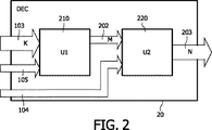
図2は、本発明の一部の実施形態によるマルチ・チャンネル・オーディオ復号器20の実施形態のブロック図を示す。復号器20は、K個のオーディオ信号103と関連パラメータ・データ104、105とをN個のオーディオ信号203に復号化するように構成される。これにおいては、KとNは、整数であり、N>K、K≧1である。K個のオーディオ信号103、即ち、代替ダウン・ミックス103と関連パラメータ・データ104、105は、N個のオーディオ信号203、即ち、マルチ・チャンネル・オーディオ信号203を表す。マルチ・チャンネル・オーディオ復号器20の例は、Nが6、即ち、5+1チャンネルに等しく、Kが2に等しい2チャンネルから5.1チャンネルへの復号器である。このようなマルチ・チャンネル・オーディオ復号器は、2チャンネル入力オーディオ信号、例えば、ステレオ入力オーディオ信号と関連パラメータとを5.1チャンネル出力オーディオ信号に復号化する。マルチ・チャンネル・オーディオ復号器20の他の例は、1チャンネルから5.1チャンネルへの復号器、2チャンネルから6.1チャンネルへの復号器、1チャンネルから6.1チャンネルへの復号器、2チャンネルから7.1チャンネルへの復号器、1チャンネルから7.1チャンネルへの復号器である。また、NがKより大きい限り、かつ、Kが1より大きいか、または1に等しい限り、NとKについて他の値を有する復号器が可能である。
FIG. 2 shows a block diagram of an embodiment of a
マルチ・チャンネル・オーディオ復号器20は、第1の装置210と、それに連結された状態で、第2の装置220とを含む。第1の装置210は、代替ダウン・ミックス103と修正パラメータ105の形である補強データとを受信し、代替ダウン・ミックス103と修正パラメータ105とから、M個の更なるオーディオ信号202、即ち、空間的ダウン・ミックス202、または、その近似値を再構築する。これにおいては、Mは、整数であり、M≧1である。修正パラメータ105は、空間的ダウン・ミックス202を表す。第1の装置210は、具体的には、修正パラメータ105が 絶対修正パラメータまたは相対修正パラメータであるかを判断し、相応にパラメータを適用するように構成される。具体的には、第1の装置210は、個々の信号ブロックに関する修正パラメータ105が受信ビットストリームの明示的データに基づいて相対パラメータまたは絶対パラメータであるか判断することができる。例えば、パラメータがその信号ブロックにおいて絶対修正パラメータまたは相対修正パラメータであるかを示す各信号ブロックについて単一のデータビットを含むことができる。
第2の装置220は、第1の装置210と修正パラメータ104とから空間的ダウン・ミックス202を受信する。第2の装置220は、空間的ダウン・ミックス202と修正パラメータ104とをマルチ・チャンネル・オーディオ信号203に復号化する。第2の装置220は、モノまたはステレオ・ダウン・ミックス・オーディオ信号202と関連パラメータ104をマルチ・チャンネル・オーディオ信号203とに復号化する従来のパラメータ系マルチ・チャンネル・オーディオ復号器とすることができる。
The
第1の装置210は、入力信号103から信号202を再構築することが必要または望ましいか判断するように構成される。このような再構築は、代替ダウン・ミックス103ではなく、空間的ダウン・ミックス信号202が第1の装置210に供給されるときには適用不可能である場合がある。第1の装置210は、入力信号103から、修正パラメータ105に含まれるのと類似のまたは同じ信号特性を生成することによって、かつ、これらの生成された信号特性を修正パラメータ105と比較することによってこれを判断することができる。この比較によって生成信号特性が修正パラメータ105と等しいかまたは実質的に等しいとわかった場合、入力信号103は、空間的ダウン・ミックス信号202と十分に類似するものであり、第1の装置210は、入力信号103を第2の装置220に転送することができる。この比較によって生成信号特性が修正パラメータ105と等しくないかまたは実質的に等しくないとわかった場合、入力信号103は、空間的ダウン・ミックス信号202に十分に類似するものではなく、第1の装置210は、入力信号103と修正パラメータ105とから空間的ダウン・ミックス信号202を再構築/近似処理することができる。
The
第1の装置210は、代替ダウン・ミックスから、代替ダウン・ミックス103を表す更なる修正パラメータ/特性を生成することができる。このような場合、第1の装置210は、代替ダウン・ミックス103と修正パラメータ105および更なる修正パラメータ(の差)とから空間的ダウン・ミックス202を再構築することができる。
The
修正パラメータ105と更なる修正パラメータは、それぞれ、空間的ダウン・ミックス202、代替ダウン・ミックス103の統計的特性を含むことができる。分散、相関、共分散などのこれらの統計的特性によって、これらのパラメータの導出元である信号が良好に表される。これらの統計的特性は、関連特性が修正パラメータ105内に含まれる特性と適合するように代替ダウン・ミックスを変換させることによって空間的ダウン・ミックス202を再構築する際に有用である。
The
図3は、本発明の一部の実施形態による送信システム70の実施形態のブロック図を示す。送信システム70は、送信チャンネル30、例えば、有線または無線通信リンクを介して符号化マルチ・チャンネル・オーディオ信号を受信器50に送信する送信器40を含む。送信器40は、上述したように、マルチ・チャンネル・オーディオ信号101を、空間的ダウン・ミックス102と、関連パラメータ104、105とに符号化するマルチ・チャンネル・オーディオ符号器10を含む。送信器40は、パラメータ104、105と、空間的ダウン・ミックス102または代替ダウン・ミックス103とを含む符号化マルチ・チャンネル・オーディオ信号を送信チャンネル30を介して受信器50に送信する手段41を更に含む。受信器50は、符号化マルチ・チャンネル・オーディオ信号を受信する手段51と、上述したように、代替ダウン・ミックス103または空間的ダウン・ミックス102と関連パラメータ104、105とをマルチ・チャンネル・オーディオ信号203に復号化するマルチ・チャンネル・オーディオ復号器20を含む。
FIG. 3 shows a block diagram of an embodiment of a transmission system 70 according to some embodiments of the invention. The transmission system 70 includes a
図4は、本発明の一部の実施形態によるマルチ・チャンネル・オーディオプレーヤ/レコーダ60の実施形態のブロック図を示す。オーディオプレーヤ/レコーダ60は、本発明の一部の実施形態によるマルチ・チャンネル・オーディオ復号器20およびマルチ・チャンネル・オーディオ符号器10もしくは本発明の一部の実施形態によるマルチ・チャンネル・オーディオ復号器20またはマルチ・チャンネル・オーディオ符号器10を含む。オーディオプレーヤ/レコーダ60は、独自の記憶装置、例えば、固体メモリまたはハードディスクを有することができる。また、オーディオプレーヤ/レコーダ60は、(記録可能)DVDディスクまたは(記録可能)CDディスクなどの着脱式記憶手段を容易にすることができる。代替ダウン・ミックス103とパラメータ104、105とを含む格納された符号化マルチ・チャンネル・オーディオ信号は、復号器20によって復号化して、オーディオプレーヤ/レコーダ60によってプレイつまり再生することができる。符号器10は、記憶手段上での格納に向けてマルチ・チャンネル・オーディオ信号を復号化することができる。
FIG. 4 shows a block diagram of an embodiment of a multi-channel audio player /
図5は、本発明の一部の実施形態によるマルチ・チャンネル・オーディオ符号器10のブロック図を示す。図5の符号器は、具体的には、図1の符号器10とすることができる。符号器10は、第1の装置110と、それに連結された状態で、第2の装置120とを含む。第1の装置110は、それぞれ、左前、左後、右前、右後、中央を含む5.1マルチ・チャンネル・オーディオ信号101と、低周波補強オーディオ信号lf、lr、rf、rr、co、lfeを受信する。第2の装置120は、それぞれ、左芸術的オーディオ信号と右芸術的オーディオ信号la、raとを含む芸術的ステレオ・ダウン・ミックス103を受信する。マルチ・チャンネル・オーディオ信号101と芸術的ダウン・ミックス103は、時間ドメイン・オーディオ信号である。第1および第2の装置110、120においては、これらの信号101、103は、セグメント化されて、周波数ドメインに変換される。
FIG. 5 shows a block diagram of a
第1の装置110においては、パラメータ・データ104を3段階で導出する。第1の段階においては、3対のオーディオ信号lfとrf、rfとrr、coとlfeをそれぞれセグメント化して、セグメント化信号を、それぞれ、セグメント化・変換装置112、113、114において周波数ドメインに変換させる。セグメント信号の結果的に得られる周波数ドメイン表現は、それぞれ、周波数ドメイン信号Lf、Lr、Rf、Rr、Co、LFEとして示される。第2の段階においては、3対のこれらの周波数ドメイン信号LfとLr、RfとRr、CoとLFEを、それぞれ、ダウン・ミキサ115、116、117においてダウンミックス処理して、それぞれ、モノ・オーディオ信号L、R、Cと、それぞれ、関連パラメータ141、142、143とを生成する。ダウン・ミキサ115、116、117は、従来のMPEG4パラメータ系ステレオ符号器とすることができる。最後に、第3の段階において、3つのモノ・オーディオ信号L、R、Cをダウン・ミキサ118内でダウン・ミックス処理して空間的ステレオ・ダウン・ミックス102と関連パラメータ144とを取得する。空間的ダウン・ミックス102は、信号LoとRoを含む。
In the
パラメータ・データ141、142、143、144は、第1の関連パラメータ・データ104の形で第1の補強データ内に含まれる。パラメータ・データ104と空間的ダウン・ミックス102は、5.1入力信号101を表す。
The
第2の装置においては、それぞれ、オーディオ信号laとraによって時間ドメインにおいて表される芸術的ダウン・ミックス信号103は、まず、セグメント化装置121内でセグメント化される。結果的に得られるセグメント化オーディオ信号127は、それぞれ、信号lasとrasを含む。次に、このセグメント化オーディオ信号127は、変換器122によって周波数ドメインに変換される。結果的に得られる周波数ドメイン信号126は、信号LaとRaを含む。最後に、セグメント化された芸術的ダウン・ミックス103の周波数ドメイン表現である周波数ドメイン信号126とセグメント化空間的ダウン・ミックス102の周波数ドメイン表現は、発生器123に供給され、発生器123は、芸術的ダウン・ミックス103が空間的ダウン・ミックス102により酷似するように、復号器が芸術的ダウン・ミックス103を修正/変換することを可能にする修正パラメータ105の形で更なる(第2の)補強データを生成する。
In the second device, the
特定の例においては、また、セグメント化時間ドメイン信号127は、セレクター124に供給される。セレクター124への他の2つの入力は、空間的ステレオ・ダウン・ミックス102の周波数ドメイン表現と制御信号128である。制御信号128は、セレクター124が芸術的ダウン・ミックス103または空間的ダウン・ミックス102を符号化マルチ・チャンネル・オーディオ信号の一部として出力するべきであるか判断する。空間的ダウン・ミックス102は、芸術的ダウン・ミックスがないときに選択することができる。制御信号128は、手作業で設定することができるか、または、芸術的ダウン・ミックス103の存在を感知することによって自動的に生成することができる。制御信号128は、対応する復号器20が後述するように制御信号128を利用することができるようにパラメータ・ビット・ストリーム内に含めることができる。したがって、この例示的な符号器によって、空間的ダウン・ミックス102または芸術的ダウン・ミックス103を含む信号を生成することができる。
In a particular example, segmented
セレクター124の出力信号102、103は、信号loとroとして示される。芸術的ステレオ・ダウン・ミックス127がセレクター124によって出力されなければならない場合、セグメント化時間ドメイン信号lasとrasは、重複加算によってセレクター124内で信号loとroに結合される。空間的ステレオ・ダウン・ミックス102が制御信号128によって表示されるように出力されなければならない場合、セレクター124は、信号LoとRoを時間ドメインに変換して、重複加算によって信号loとroに結合する。時間ドメイン信号loとroは、5.1チャンネルから2チャンネルへの符号器10のステレオ・ダウン・ミックスを成す。
The output signals 102 and 103 of the
発生器123を以下で更に詳細に説明する。発生器123の機能は、第2の補強データ、具体的には、芸術的ダウン・ミックス103がある意味で元の空間的ダウン・ミックス102に類似するように、芸術的ダウン・ミックス103の変換を記述する修正パラメータを判断することである。
一般に、この変換は、以下のように記述することができる。

![]()
![]()
![]()
![]()
(N+2)×2変換行列
あるいは、修正パラメータ105は、信号特性、例えば、空間的ダウン・ミックス102のエネルギーまたは電力値および相関値もしくはエネルギーまたは電力または相関値を含む。その後、復号器20は、芸術的ダウン・ミックス103から当該の信号特性を生成することができる。空間的ダウン・ミックス102と芸術的ダウン・ミックス103の信号特性によって、復号器20は、変換行列
具体的には、発生器123は、相対修正データも絶対修正データも生成し、かつ、個々の信号ブロック(またはセグメント)についてこのデータから選択するように構成される。したがって、符号化信号に関する修正パラメータ105は、異なる信号ブロックに向けて絶対修正データも相対修正データも含む。絶対修正データとは対照的に、相対修正データは、芸術的ダウン・ミックス103に対して空間的ダウン・ミックス102を記述する。具体的には、相対修正データは、空間的ダウン・ミックス・サンプルに(より密接に)対応するように芸術的ダウン・ミックス・サンプルを修正することを可能にする差分データとすることができ、一方、絶対ダウン・ミックス・データは、芸術的ダウン・ミックス・サンプルを参照または芸術的ダウン・ミックス・サンプルに依存することなく、直接、空間的ダウン・ミックス・サンプルに対応することができる。
Specifically, the
以下を含め、元のステレオ・ダウン・ミックス102に似るように芸術的ダウン・ミックス103を修正する方法が幾つかあることが理解されるであろう。
I.波形の適合。
II.統計的特性の適合。
It will be appreciated that there are several ways to modify the
I. Waveform fit.
II. Statistical property fit.
a.左右のチャンネルのエネルギーまたは電力の適合。 a. Adapt the energy or power of the left and right channels.
b.左右のチャンネルの共分散行列の適合。
III.左右のチャンネルのエネルギーまたは電力の拘束下での波形の可能な最良の適合を取得する。
IV.上述した方法IからIIIを混合する。
b. Fit the covariance matrix of the left and right channels.
III. Get the best possible fit of the waveform under the constraints of the energy or power of the left and right channels.
IV. Mix methods I through III described above.
明確にするために、(1)の補助チャンネル
![]()
I.波形適合(方法I)
(1) Auxiliary channel for clarity
![]()
I. Waveform fitting (Method I)
芸術的ダウン・ミックス103と空間的ダウン・ミックス102の波形の適合は、修正芸術的ダウン・ミックスの左信号も右信号も芸術的ステレオ・ダウン・ミックス103の左右の信号の線形結合として表すことによって得ることができる。
その後、(2)の行列
パラメータα1、α2、β1およびβ2を選ぶ方法は、空間的ダウン・ミックス信号LsとRsとその推定値(即ち、修正芸術的ダウン・ミックス信号
方法II.a:左右の信号のエネルギーを適合させることをここで論じる。それぞれ、
これらの選択で、それぞれ、信号
方法II.b:芸術的ステレオ・ダウン・ミックス103と空間的ダウン・ミックス102の共分散行列を適合させるには、これらの行列を以下のように固有値分解を使用して分解することができる。
![]()
![]()
![]()
![]()
行列
行列
(12)から、変換行列
(3)を仮定すると、パラメータα1、α2、β1およびβ2は、エネルギー拘束下で(4)と(5)を最小限に抑えることによって得ることができる。
異なる方法の混合に関して、可能な組み合わせとして、方法II.aと方法II.bの混合または方法II.aと方法IIIの混合が挙げられる。以下のように進むことができる。
a)方法II.b/IIIを使用したときに得られる
b)この波形適合が不良である場合、方法II.aを使用する。
c)この波形適合の質の関数として、変換行列を混合させることによって、2つの方法の漸進的な移行を確保する。
With regard to the mixing of the different methods, possible combinations of method II. a and method II. Mixing b or method II. A mixture of a and method III may be mentioned. You can proceed as follows.
a) Method II. Obtained when using b / III
b) If this waveform fit is bad, method II. Use a.
c) Ensure a gradual transition between the two methods by mixing the transformation matrix as a function of the quality of this waveform fit.
これを、数学的に以下のように表すことができる。 This can be expressed mathematically as follows.
(3)と(2)を使用して、変換行列
この行列は、2つのベクトル
方法II.bまたは方法IIIのいずれかを使用して得られた
方法II.bまたは方法IIIのいずれかを使用して得られた
![]()
![]()
![]()
![]()
方法II.a、II.b、IIIの変換行列
方法II.aと方法II.bを混合する変換行列
方法II.aと方法IIIを混合する変換行列
ここで、2つの補強層チャンネルに対応する2つの補助チャンネルを考慮すると、上記の方程式(1)は、以下のように書き換えることができる。
特定の例示的なシステムにおいては、第2の補強層は、2つの異なるタイプのデータを含むことができる。 In certain exemplary systems, the second reinforcement layer can include two different types of data.
第1のタイプのデータは、方程式(1)の行列T内に含まれたパラメータを含む。これらのパラメータは、この例においては、信号帯域全体について計算され、ある意味で空間的ダウン・ミックスに似るように芸術的ステレオ・ダウン・ミックスを変換させるものである。したがって、この種のパラメータは、元の空間的ダウン・ミックスにより酷似する修正芸術的ダウン・ミックスを実現することができるが、(必ずしも)復号器が空間的ダウン・ミックスを正確に生成することを可能にするわけではない。各時間/周波数タイルについては、4つのパラメータのみが必要であり、即ち、Tの値が必要とされる(T11、T12、T21、T22)。これらのパラメータは、絶対コーディングまたは差分コーディングすることができ、符号器10は、具体的には絶対符号化と差分符号化との間で切り替わることができる。
The first type of data includes the parameters included in the matrix T of equation (1). These parameters are calculated for the entire signal band in this example, and in a sense, transform the artistic stereo downmix to resemble a spatial downmix. Thus, this type of parameter can achieve a modified artistic downmix that more closely resembles the original spatial downmix, but (necessarily) ensures that the decoder generates the spatial downmix correctly. It doesn't make it possible. For each time / frequency tile, only four parameters are required, i.e. the value of T is required (T11, T12, T21, T22). These parameters can be absolute coding or differential coding, and the
第2のタイプのデータは、実際の空間的ダウン・ミックスに対応するものであり、この特定の例においては、空間的ダウン・ミックスの帯域限定バージョンの表現である。具体的には、このタイプのデータは、空間的ダウン・ミックスの低周波部分(例えば、1.7kHzを下回る周波数)を表す。これによって、同じ、例えば、統計的特性を有する信号をただ生成するのではなく、復号器にて空間的ダウン・ミックスのこの部分を非常に正確に再構築することが可能になる(行列Tの場合と同様に)。この種のデータは、芸術的ダウン・ミックスに絶対的にまたは相対的にコーディングすることができる。具体的には、このタイプのデータを差分符号化することができる。例えば、変換行列Tを芸術的ダウン・ミックスに適用すると(例えば、方程式(26)を参照されたい)、その信号と空間的ダウン・ミックスの差を符号化することができる。 The second type of data corresponds to the actual spatial downmix, and in this particular example is a representation of a band limited version of the spatial downmix. Specifically, this type of data represents the low frequency portion of the spatial down mix (eg, frequencies below 1.7 kHz). This makes it possible to reconstruct this part of the spatial down-mix very accurately at the decoder rather than just generating a signal with the same, eg statistical properties (of the matrix T As in the case). This kind of data can be coded absolutely or relative to an artistic down mix. Specifically, this type of data can be differentially encoded. For example, applying the transformation matrix T to an artistic down mix (see, eg, equation (26)) can encode the difference between that signal and the spatial down mix.
したがって、一部の実施形態においては、第2の補強データは、補強データの第1の部分と第2の部分に分割され、第1の部分は、第2の部分ほど正確には空間的ダウン・ミックスを記述しない。一般的に、第2の補強データの第1の部分の対応するデータ転送速度は、第2の部分より遅い。第2の補強データの第2の部分の補強データは、ダウン・ミックスの一部のみに関連することができ、具体的には、低周波部分にのみ関連することができる。 Thus, in some embodiments, the second augmentation data is divided into a first portion and a second portion of the augmentation data, where the first portion is more accurately spatially down than the second portion.・ Do not describe the mix. In general, the corresponding data transfer rate of the first portion of the second augmented data is slower than the second portion. The reinforcement data of the second part of the second reinforcement data can be related only to a part of the down mix, in particular it can only be related to the low frequency part.
一部の実施形態においては、発生器123は、第2の補強データの第1の部分と第2の部分の両方について、個別にまたはまとめて、絶対データと相対データとから選択するように配置することができる。他の実施形態においては、発生器123は、データの部分の1つのみについて絶対データと相対データから選択することができる。具体的には、以下では、第2の補強データの第1の部分がTのパラメータを含み、一方、第2の部分が空間的ダウン・ミックスの低周波表現を含み、絶対データと相対データとからの動的な選択は、第2の補強データの第2の部分にのみ適用される種々の実施形態について説明する。
In some embodiments, the
第2の補強データの第2の部分の相対データは、これらの実施形態においては、例えば、第1の部分の補強データが適用された後の芸術的ダウン・ミックスに対する差分値(即ち、修正芸術的ダウン・ミックスに対する差分値)として生成することができる。 The relative data of the second part of the second augmentation data is, in these embodiments, for example the difference value for the artistic down-mix after the first part of the augmentation data has been applied (ie the modified art). As a difference value for a dynamic down-mix).
以下においては、発生器123が第2の補強データの第2の部分について絶対データと相対データとからのみ選択する実施形態について以下で説明する。
In the following, an embodiment in which the
第2の補強データの第1の部分と第2の部分の一部に関する絶対補強データは、この例においては、以下を設定することによって関連時間/周波数タイルについて導出することができる。
更に、第2の補強データの第1および第2の部分のその部分については、関連時間/周波数タイルに関する相対補強データは、具体的には、以下を設定することによって差分データとして導出することができる。
ここで、パラメータT11、T12、T21、T22は、方程式(2)の行列Tを構成する。
このようにして、発生器123は、芸術的ダウン・ミックス103について絶対補強データと相対補強データの両方を生成することができ、復号器は、マルチ・チャンネル補強データの生成に使用される空間的ダウン・ミックス102により酷似する修正芸術的ダウン・ミックスを生成することができる。
In this way, the
発生器123は、更に、絶対補強データと相対補強データとから選択するように構成される。この選択は、この特定の例においては、個々の信号ブロック(例えば、個々のセグメント)について、かつ、これらの信号ブロック内の信号の特性に基づいて行われる。具体的には、発生器123は、任意の信号ブロックについて絶対補強データと相対補強データの特性を評価することができ、任意の信号ブロックについてどちらのデータを補強層に含めるべきか判断することができる。更に、発生器123は、どちらのデータが選択されたかの表示を含むことができ、その結果、復号器は、受信補強データを正しく適用することができる。
The
一部の実施形態においては、発生器123は、符号化を評価して、絶対補強データまたは相対補強データを最も効率的に符号化することができる(例えば、任意の精度を得るための最少数のビットで)か判断することができる。強引な方法として、実際に両方のタイプの補強データを符号化して符号化データサイズを比較することができる。しかしながら、これは、一部の実施形態においては複雑な方法となる恐れがあり、例示的な符号器10においては、発生器123は、相対補強データの信号エネルギーに対する絶対補強データの信号エネルギーを評価して、2つの比較に基づいてどちらのタイプのデータを含めるべきか選択する。
In some embodiments, the
具体的には、オーディオ・コーダについては、ビットレートに関して、できるだけ小さなエネルギーで信号を符号化することが有益であることが多い。したがって、発生器123は、最低信号エネルギーを有するタイプの補強データを選択する。特に、相対補強データは、
![]()
![]()
異なる補強データ間の切り替えに関する問題は、一部の顕著な人為的影響が起こる恐れがあるということである。例示的符号器10においては、発生器123は、異なる補強データ間で漸進的に切り替わる機能性も含む。したがって、切り替わりは、1つの信号ブロック内の1つのタイプの補強データから次の信号ブロック内の別のタイプに直に切り替わるのではなく、一方のセットのデータから他方のセットに漸進的に行われる。
The problem with switching between different augmentation data is that some significant artifacts can occur. In the
したがって、(1つの信号ブロックを下回るかまたは上回る持続時間を有する)時間間隔中、発生器123は、絶対補強データと相対補強データの結合として補強データを生成する。この結合は、例えば、異なるタイプのデータ間の補間によって達成することができるか、または、この結合では、重複加算法を用いることができる。
Thus, during a time interval (having a duration below or above one signal block), the
特定の例として、異なるタイプの補強データ間で急に切り替わる
![]()
![]()
現在のフレームが差分コーディングされる場合。
ここで、αkは、k番目のフレーム内のαの値を示し、δは、適応速度である。δ=0.33という値は、多くのシナリオにおいて確実に人為的影響がない符号化を実現することができる。方程式(29)内に示す信号
![]()
![]()
The current frame is differentially coded.
Here, α k indicates the value of α in the k-th frame, and δ is the adaptation speed. A value of δ = 0.33 can realize coding without artifacts reliably in many scenarios. Signal shown in equation (29)
ここの説明では個別にこれらのM個のチャンネルの各々の(チャンネル間の)コーディングと共に差分モードと絶対モードを用いることが中心となっているが、他の実施形態では、異なる符号化法を用いることができることが理解されるであろう。例えば、M=2の場合、次のステップは、例えば、ステレオ信号の(チャンネル間の)コーディングを行うときにはM/Sコーディング(Mid/Sideコーディング、したがって、和信号と差信号をコーディング)を適用することとすることができる。多くの実施形態においては、これは、個々のチャンネルの(チャンネル間の)コーディングの差分モードと絶対モードの両方において有利であろう。 The description here focuses on using differential mode and absolute mode with coding (interchannel) for each of these M channels individually, but other embodiments use different encoding methods. It will be understood that this is possible. For example, if M = 2, the next step is to apply M / S coding (Mid / Side coding, thus coding sum and difference signals), for example when coding stereo signals (between channels). Can be. In many embodiments, this may be advantageous in both differential and absolute modes of coding of individual channels (between channels).
変換行列T'の諸要素は、実数値または複素数値とすることができる。これらの諸要素は、以下のように修正パラメータに符号化することができる。実数でありかつ正である変換行列
図6は、図5の発生器123の例をより詳細に示す。この例においては、発生器123は、信号ブロック・プロセッサ145を含み、信号ブロック・プロセッサ145は、周波数ドメイン空間的ダウン・ミックス102と周波数ドメイン芸術的ダウン・ミックス126とを受信して、信号を信号ブロックに分割する。各信号ブロックは、所定の持続時間の時間間隔に対応することができる。一部の実施形態においては、信号ブロックは、あるいはまたは更に、周波数ドメイン内で分割することができ、かつ、例えば、変換サブチャンネルは、異なる信号ブロックでまとめてグループ化することができる。
FIG. 6 shows an example of the
信号ブロック・プロセッサ145は、絶対補強データ・プロセッサ146に連結され、絶対補強データ・プロセッサ146は、先述したように、個々の信号ブロックについて絶対補強データを生成する。更に、信号ブロック・プロセッサ145は、相対補強データ・プロセッサ147に連結され、相対補強データ・プロセッサ147は、先述したように、個々の信号ブロックについて相対補強データを生成する。相対補強データと絶対補強データは、信号ブロック内の信号特性に基づいて判断され、具体的には、任意の時間/周波数タイル・グループに関する補強データは、その時間/周波数タイル・グループのみに基づいて判断することができる。
絶対補強データ・プロセッサ146は、第1の信号エネルギー・プロセッサ148に連結され、第1の信号エネルギー・プロセッサ148は、先述したように、各信号ブロック内の絶対補強データの信号エネルギーを判断する。同様に、相対補強データ・プロセッサ147は、第2の信号エネルギー・プロセッサ149に連結され、第2の信号エネルギー・プロセッサ149は、先述したように、各信号ブロック内の相対補強データの信号エネルギーを判断する。
The absolute
第1および第2の信号エネルギー・プロセッサ148、149は、選択プロセッサ150に連結され、選択プロセッサ150は、各信号ブロックについて、どちらのタイプが最低信号エネルギーを有するかによって絶対補強データまたは相対補強データから選択する。
The first and second
選択プロセッサ150は、補強データ・プロセッサ151に供給され、補強データ・プロセッサ151は、更に、補強データ・プロセッサ146と相対補強データ・プロセッサ147とに連結される。選択プロセッサ151は、どちらのタイプの補強データが選択されたかを示す制御信号を受信して、相応に、その補強データを選択補強データとして生成する。更に、選択プロセッサ151は、切り替え時間間隔中の絶対パラメータと相対パラメータ間の補間を含む漸進的な切り替えを行うように配置される。
The
選択プロセッサ151は、符号化プロセッサ152に連結され、符号化プロセッサ152は、特定のプロトコルに従って補強データを符号化する。更に、符号化プロセッサ152は、例えば、各信号ブロックについてビットを設定してデータタイプを表示することによって、どちらのタイプのデータが選択されているかを示すデータを符号化する。符号化プロセッサ152からのこの符号化データは、符号器10によって生成された符号化ビット・ストリーム内に含まれる。
The
図7は、具体的には図2のオーディオ復号器20とすることができる、本発明の一部の実施形態によるマルチ・チャンネル・オーディオ復号器の別の実施形態のブロック図を示す。
FIG. 7 shows a block diagram of another embodiment of a multi-channel audio decoder according to some embodiments of the present invention, which may specifically be the
復号器20は、第1の装置210と、それに連結された状態で、第2の装置220を含む。第1の装置210は、ダウン・ミックス信号loとroおよび修正パラメータ105を入力として受信する。この入力は、例えば、図1または図5の符号器10からの単一のビット・ストリームとして受信することができる。ダウン・ミックス信号loとroは、空間的ダウン・ミックス102または芸術的ダウン・ミックス103の一部とすることができる。
The
第1の装置210は、セグメント化・変換装置211とダウン・ミックス修正装置212とを含む。ダウン・ミックス信号loとroは、それぞれ、セグメント化され、セグメント化信号は、セグメント化・変換装置211内で周波数ドメインに変換される。セグメント化ダウン・ミックス信号の結果的に得られる周波数ドメイン表現は、それぞれ、周波数ドメイン信号LoとRoとして示される。次に、周波数ドメイン信号LoとRoは、ダウン・ミックス修正装置212内で処理される。ダウン・ミックス修正装置212の機能は、空間的ダウン・ミックス202に似るように入力ダウン・ミックスを修正すること、即ち、芸術的ダウン・ミックス103と修正パラメータ105から空間的ダウン・ミックス202を再構築することである。
The
空間的ダウン・ミックス102が復号器20によって受信された場合、ダウン・ミックス修正装置212は、ダウン・ミックス信号LoとRoを修正する必要はなく、これらのダウン・ミックス信号LoとRoは、単に、空間的ダウン・ミックス202のダウン・ミックス信号LdとRdとして第2の装置220に渡すことができる。制御信号217は、入力ダウン・ミックスの修正の必要性があるかどうか、即ち、入力ダウン・ミックスが空間的ダウン・ミックスであるのかそれとも代替ダウン・ミックスであるのかを表示することができる。制御信号217の生成は、例えば、入力ダウン・ミックスと、所望の空間的ダウン・ミックスの信号特性を記述することができる関連パラメータ105とを分析することによって、復号器20内で内部的に行なうことができる。入力ダウン・ミックスが所望の信号特性に適合する場合、修正が不要であることを表示するように制御信号217を設定することができる。あるいは、制御信号217は、手作業で設定することができるか、または、その設定は、例えば、パラメータセット105において符号化マルチ・チャンネル・オーディオ信号の一部として受信することができる。
When the spatial down
符号器20が芸術的ダウン・ミックス103を受信し、制御信号217が、受信ダウン・ミックス信号LoとRoはダウン・ミックス修正装置212によって修正されるべきであると表示する場合、復号器は、受信修正パラメータの表現によって2通りに動作することができる。パラメータが芸術的ダウン・ミックスから空間的ダウン・ミックスへの相対変換を表す場合(即ち、パラメータが相対補強データである場合)、符号器内で行われる動作と逆に修正パラメータを芸術的ダウン・ミックスに適用することによって、直接、変換変数が取得される。異なる実施形態においては、これは、例えば、第2の補強データの第2の部分に適用することができる。
If
一方、送信パラメータが空間的ダウン・ミックスの絶対特性を表す場合、復号器は、直接、空間的ダウン・ミックス・サンプルによって芸術的ダウン・ミックス・サンプルを置き換えることができる。例えば、第2の補強データの第2の部分が単に空間的ダウン・ミックスの時間/周波数タイル・サンプルにある場合、復号器は、直接、芸術的ダウン・ミックスの対応する時間/周波数タイル・サンプルをこれらで置き換えることができる。復号器が、まず、実際に送信された芸術的ダウン・ミックスの対応する特性を計算することも可能であることが理解されるであろう。この情報(送信パラメータと送信芸術的ダウン・ミックスの算出特性)を用いて、送信芸術的ダウン・ミックス(の特性)から空間的ダウン・ミックス(の特性)への変換を記述する変換変数が判断される。より具体的にいうと、変換行列Tの判断は、先述した方法II.aまたは(若干修正された)II.bを用いて行なうことができる。 On the other hand, if the transmission parameter represents the absolute characteristic of the spatial down mix, the decoder can directly replace the artistic down mix sample with the spatial down mix sample. For example, if the second portion of the second augmentation data is simply in the spatial downmix time / frequency tile sample, then the decoder directly corresponds to the artistic downmix corresponding time / frequency tile sample. Can be replaced with these. It will be appreciated that the decoder can also first calculate the corresponding characteristics of the actually transmitted artistic down mix. Using this information (transmission parameters and transmission artistic down-mix calculation characteristics), a transformation variable describing the transformation from transmission artistic down-mix (characteristic) to spatial down-mix (characteristic) is determined. Is done. More specifically, the transformation matrix T is determined by the method II. a or (slightly modified) II. b can be used.
方法II.aは、絶対エネルギーが第2の補強データの第1の部分において送信された場合に用いることができる。送信(絶対)パラメータ
![]()
![]()
送信ダウン・ミックス
変換行列
具体的には、ダウン・ミックス修正装置212は、芸術的ダウン・ミックスと修正パラメータ105を受信ビット・ストリームから抽出する機能性を含む。芸術的ダウン・ミックスは、(復号器によって使用される信号ブロックに対応する)信号ブロックに分割される。各信号ブロックについては、ダウン・ミックス修正装置212は、ビット・ストリームの受信データの表示を評価して、この信号ブロックについて第1および第2の部分には相対第2の補強データまたは絶対第2の補強データが供給されているか判断する。その後、ダウン・ミックス修正装置212は、表示データに応答して、絶対補強データまたは相対補強データとして第2の補強データの第1および第2の部分を適用する。
Specifically, the
変換行列要素T12とT21が0に設定されたとき、複雑性は低いが高い性能を達成することができることが既にわかっている。以下においては、ダウン・ミックス修正装置212の一部の特定の実行例について、この制限と共に説明する。しかしながら、種々の実行例は、T12およびT21もしくはT12またはT21が0と異なる場合に容易に拡張することができることが理解されるであろう。
When the conversion matrix elements T 12 and T 21 is set to 0, is already known to be capable of low complexity is to achieve high performance. In the following, some specific implementations of the
芸術的ダウン・ミックス信号向けに送信された第2の補強データの第2の部分の補強データがない場合、第1の装置210を図8に示すように実行することができる。時間ドメイン・ステレオ・ダウン・ミックス信号loとroが、まず、セグメント化されて、QMF変換によって周波数ドメインに変換され、その結果、芸術的ステレオ・ダウン・ミックスの時間/周波数タイルを表す信号LaとRaが得られる。次に、これらの信号は、変換行列Tを用いて変換され、その結果、信号T11LaとT12Raが得られる。
If there is no augmentation data for the second portion of the second augmentation data transmitted for the artistic down-mix signal, the
補強データは、時間ドメインおよび周波数ドメインもしくは時間ドメインまたは周波数ドメインにおいて生成しかつ適用することができることが理解されるであろう。したがって、コーディングされた時間ドメイン補強データ(Lenh、Renh)をビット・ストリーム内に含めることが可能である。しかしながら、一部の適用においては、時間ドメイン補強データではなく、コーディングされた周波数ドメイン補強データ含めることが有利である可能性がある。例えば、多くの符号器においては、補強データは、時間/周波数タイルに関しては周波数ドメイン内で生成され、かつ、時間ドメイン信号を生成するために、周波数ドメインから時間ドメインへの変換が符号器にて必要とされる。更に、当該の補強データを適用するために、復号器は、データを時間ドメインから周波数ドメインに変換する。したがって、ドメイン変換回数は、補強データを周波数ドメインに含めることによって少なくすることができる。 It will be appreciated that the augmentation data can be generated and applied in the time domain and frequency domain or time domain or frequency domain. Accordingly, coded time domain augmentation data (L enh , R enh ) can be included in the bit stream. However, in some applications it may be advantageous to include coded frequency domain reinforcement data rather than time domain reinforcement data. For example, in many encoders, augmentation data is generated in the frequency domain for time / frequency tiles, and a frequency domain to time domain transform is performed at the encoder to generate a time domain signal. Needed. Furthermore, in order to apply the augmented data, the decoder converts the data from the time domain to the frequency domain. Therefore, the number of domain transformations can be reduced by including reinforcement data in the frequency domain.
一部の実施形態においては、芸術的ダウン・ミックスと補強データとを生成するために、異なる時間から周波数への変換を用いることができる。例えば、芸術的ダウン・ミックスの符号化では、QMF変換を用いることができ、一方、補強データでは、MDCT変換が用いられる。この場合、補強データは、(MDCT)周波数ドメイン内に含めることができ、2つの周波数ドメイン間で直接行われる変換は、図9に示すように、ダウン・ミックス修正装置212によって行なうことができる。
In some embodiments, different time-to-frequency transformations can be used to generate artistic downmix and augmentation data. For example, artistic down-mix encoding can use QMF transform, while augmented data uses MDCT transform. In this case, the augmentation data can be included in the (MDCT) frequency domain, and the conversion performed directly between the two frequency domains can be performed by the down-
この例においては、変換行列T*は、単に、方程式(2)の変換行列Tとすることができる。しかしながら、スイッチング時の人為的影響を低減するために、T*は、方程式(2)の変換行列Tに対応することができるが、漸進的な切り替えに向けて修正される。具体的には、行列T*は、方程式(30)によって求められるような因数αを含むことができ、その場合、絶対補強データまたは相対補強データに関する判断は、ビット・ストリームから検索される。この方法は、第2の補強データの第2の部分の補強層データが存在する信号ブロック/周波数帯域に使用され、その他の場合、図8の方法を用いることができる。 In this example, the transformation matrix T * can simply be the transformation matrix T of equation (2). However, T * can correspond to the transformation matrix T in equation (2), but is modified for gradual switching in order to reduce artifacts during switching. Specifically, the matrix T * can include a factor α as determined by equation (30), in which case a decision regarding absolute or relative reinforcement data is retrieved from the bit stream. This method is used for signal blocks / frequency bands in which the enhancement layer data of the second part of the second enhancement data exists, and in other cases, the method of FIG.
補強データ(Lenh、Renh)が時間ドメインにおいて提供された場合、図10に示すように、図9と類似の方法を用いることができる。しかしながら、この場合、周波数から周波数への変換の代わりに、時間から周波数への変換が用いられ、この時間から周波数への変換は、具体的には、芸術的ダウン・ミックスの符号化にQMF変換が用いられるときに時間からQMFへのドメイン変換によるものとすることができる。したがって、この例においては、補強データは、周波数ドメインにおいて適用される。 If reinforcement data (L enh , R enh ) is provided in the time domain, a method similar to FIG. 9 can be used, as shown in FIG. However, in this case, instead of frequency-to-frequency conversion, time-to-frequency conversion is used, and this time-to-frequency conversion is specifically a QMF conversion for artistic downmix coding. Can be due to time-to-QMF domain conversion. Therefore, in this example, the reinforcement data is applied in the frequency domain.
多くの実施形態においては、第1の装置210において1回の時間ドメインから周波数ドメインへの変換しか用いられない時間ドメイン補強データに関する復号器の実行を用いることができる。
In many embodiments, a decoder implementation for time domain augmentation data that only uses one time domain to frequency domain transform in the
具体的には、以下の差分補強データ・パラメータを使用することができる。
図11は、方程式(34)と方程式(35)に基づく時間ドメイン補強データに関するダウン・ミックス修正装置212の効率的な実行が行われることを示す。明瞭さを期すために、行列TのT12とT21は、0に設定される。図10の実行例と比較すると、図11の実行例によって必要とされる時間からQMFへのドメイン変換は1回だけである。
FIG. 11 shows that an efficient implementation of the down-
したがって、上述したように、ダウン・ミックス修正装置212は、マルチ・チャンネル補強データに使用される空間的ダウン・ミックスに非常に酷似している信号202を生成する。これは、第2の装置220によって効果的に使用して2チャンネル・オーディオ信号を完全サラウンド・サウンド・マルチ・チャンネル信号に拡張することができる。更に、各信号ブロックについて最も妥当なタイプの補強データ(相対または絶対)を動的にかつ柔軟に選択することによって、実質的により効率的な符号化が達成され、かつ、質とデータ転送速度との比率が向上したマルチ・チャンネル符号化/復号化が達成される。
Thus, as described above, the
第2の装置220は、再構築空間的ダウン・ミックス202と関連パラメータ104とを5.1チャンネル出力信号203に復号化する従来の2チャンネルから5.1チャンネルへの復号器とすることができる。先述したように、パラメータ・データ104は、パラメータ・データ141、142、143、144を含む。第2の装置220は、符号器10内の第1の装置110の逆の処理を行う。第2の装置220は、アップ・ミキサ221を含み、アップ・ミキサ221は、ステレオ・ダウン・ミックスと関連パラメータ144とを3つのモノ・オーディオ信号L、R、Cに変換し、それぞれ、モノ・オーディオ信号L、R、Cの各々は、それぞれ、相関分離器222、225、228内で相関分離される。その後、混合行列223によってモノ・オーディオ信号、その相関分離オーディオ信号、関連パラメータ141が信号LfとLrに変換される。同様に、混合行列226によって、モノ・オーディオ信号R、その相関分離オーディオ信号、関連パラメータ142が、信号RfとRrに変換され、混合行列229によって、モノ・オーディオ信号C、その相関分離オーディオ信号、関連パラメータ143が信号CoとLFEに変換される。最後に、3つの対のセグメント化周波数ドメイン信号LfとLr、RfとRf、CoとLFEは、それぞれ、3つの対の出力信号lfとlr、rfとrr、coとlfeを取得するために、それぞれ、逆変換器224、227、230において時間ドメインに変換され、かつ、重複加算によって結合される。出力信号lfとlr、rfとrr、coとlfeは、復号化マルチ・チャンネル・オーディオ信号203を成す。
The
マルチ・チャンネル・オーディオ符号器10とマルチ・チャンネル・オーディオ復号器20は、デジタル・ハードウェアによって、または、デジタル信号プロセッサまたは汎用マイクロプロセッサによって実行されるソフトウェアによって実行することができる。
以上の説明では、明瞭さを期すために、異なる機能装置およびプロセッサを参照しながら本発明の種々の実施形態を説明したことが理解されるであろう。しかしながら、本発明から逸脱することなく、異なる機能装置またはプロセッサ間での機能性の任意の適切な配分を用いることができることが明らかであろう。例えば、別個のプロセッサまたは制御装置によって実行されるように示した機能性は、同じプロセッサまたは制御装置によって実行することができる。したがって、特定の機能装置への言及は、厳密な論理的または物理的構造または構成を示すのではなく、説明した機能性を実現する適切な手段への言及としてのみ見るべきである。 It will be understood that the foregoing description has described various embodiments of the invention with reference to different functional units and processors for the sake of clarity. However, it will be apparent that any suitable distribution of functionality between different functional devices or processors may be used without departing from the invention. For example, functionality illustrated to be performed by separate processors or controllers can be performed by the same processor or controller. Accordingly, references to specific functional devices should not be seen as strict logical or physical structures or configurations, but only as references to appropriate means of implementing the described functionality.
本発明は、ハードウェア、ソフトウェア、ファームウェアまたはこれらの任意の組み合わせを含む任意の適切な形態で実行することができる。本発明は、任意選択的に、1つまたはそれ以上のデータ・プロセッサおよびデジタル信号プロセッサもしくは1つまたはそれ以上のデータ・プロセッサまたはデジタル信号プロセッサ上で実行されるコンピュータ・ソフトウェアとして、少なくとも部分的に実行することができる。本発明の実施形態の要素および構成品は、任意の適切な方法で物理的、機能的、および論理的に実行することができる。実際、機能性は、単一の装置内で、複数の装置内で、または他の機能装置の一部として実行することができる。この点を踏まえると、本発明は、単一の装置内で実行することができるか、または、異なる装置およびプロセッサ間に物理的かつ機能的に配分することができる。 The invention can be implemented in any suitable form including hardware, software, firmware or any combination of these. The present invention is optionally at least partially as computer software running on one or more data processors and digital signal processors or one or more data processors or digital signal processors. Can be executed. The elements and components of an embodiment of the invention may be physically, functionally and logically implemented in any suitable way. Indeed, the functionality can be performed within a single device, within multiple devices, or as part of another functional device. In light of this, the present invention can be executed within a single device or can be physically and functionally distributed between different devices and processors.
本発明を一部の実施形態に関連して説明してきたが、本明細書で定める特定の形態に限定されることを意図するものではない。むしろ、本発明の範囲は、添付の特許請求の範囲によってのみ限定される。更に、機能は特定の実施形態に関連して説明されているように思われる場合があるが、当業者は、説明した種々の実施形態の様々な特長は、本発明に従って組み合わせることができることを認識するであろう。特許請求の範囲においては、「を含む」という用語は、他の要素またはステップの存在を除外するものではない。 Although the present invention has been described in connection with some embodiments, it is not intended to be limited to the specific form set forth herein. Rather, the scope of the present invention is limited only by the accompanying claims. Further, while functions may appear to be described in connection with particular embodiments, those skilled in the art will recognize that the various features of the various described embodiments can be combined in accordance with the present invention. Will do. In the claims, the term “comprising” does not exclude the presence of other elements or steps.
更に、個別に記載しているが、複数の手段、要素または方法のステップは、例えば、単一の装置またはプロセッサによって実行することができる。更に、個々の特長は、異なる請求項に含むことができるが、これらは、恐らくは有利に組み合わせることができ、異なる請求項に含めることは、種々の特長の組み合わせが実現不可能および不利もしくは実現不可能または不利であることを意味するものではない。また、1つのカテゴリーの請求項内に特長を含めることは、このカテゴリーへの限定を意味するのではなく、その特長が必要に応じて他の請求項のカテゴリーに等しく適用可能であることを示すものである。更に、請求項内での種々の特長の順番は、種々の特長を加工しなければならない何らかの特定の順番を意味するものではなく、特に、方法に関する請求項における個々のステップの順番は、この順番で個々のステップを実行しなければならないことを意味するものではない。むしろ、個々のステップは、任意の適切な順番で実行することができる。更に、単数での言及は、複数を排除するものではない。したがって、「1つの」、「第1の」、「第2の」などの言及は、複数を排除するものではない。請求項内の各種参照符号は、単に、明確にする例として提示されているものであり、いかなる点においても種々の請求項の範囲を限定すると解釈すべきではない。 Furthermore, although individually listed, a plurality of means, elements or method steps may be implemented by eg a single device or processor. Furthermore, although individual features may be included in different claims, they may possibly be combined in an advantageous manner, and inclusion in different claims may result in a combination of various features not feasible and disadvantageous or not feasible. It does not mean that it is possible or disadvantageous. Also, including a feature within a category of claims does not imply a limitation to this category, but indicates that the feature is equally applicable to other claim categories as needed. Is. Further, the order of the various features in the claims does not imply any particular order in which the various features must be processed, and in particular, the order of the individual steps in the method claims. Does not mean that individual steps must be performed. Rather, the individual steps can be performed in any suitable order. Further, singular references do not exclude a plurality. Thus, references to “one”, “first”, “second”, etc. do not exclude a plurality. Various reference signs in the claims are provided merely as a clarifying example and shall not be construed as limiting the scope of the various claims in any way.
10 マルチ・チャンネル・オーディオ符号器
20 マルチ・チャンネル・オーディオ復号器
30 送信チャンネル
40 送信器
50 受信器
60 マルチ・チャンネル・オーディオプレーヤ/レコーダ
70 送信システム
101 マルチ・チャンネル・オーディオ信号
102 ダウン・ミックス・オーディオ信号
103 代替ダウン・ミックス信号
104 第1の関連パラメータ・データ
105 第2の関連パラメータ・データ
110 第1の符号化装置
112〜114 セグメント化・変換装置
115〜118 ダウン・ミキサ
120 第2の符号化装置
121 セグメント化装置
122 変換器
123 発生器
124 セレクター
126 周波数ドメイン信号
127 セグメント化オーディオ信号
128 制御信号
141〜144 パラメータ・データ
145 信号ブロック・プロセッサ
146 絶対補強データ・プロセッサ
147 相対補強データ・プロセッサ
148 第1の信号エネルギー・プロセッサ
149 第2の信号エネルギー・プロセッサ
150 選択プロセッサ
151 補強データ・プロセッサ
152 符号化プロセッサ
202 空間的ダウン・ミックス
203 マルチ・チャンネル・オーディオ信号
210 第1の装置
211 セグメント化・変換装置
212 ダウン・ミックス修正装置
217 制御信号
220 第2の装置
221 アップ・ミキサ
222、225、228 相関分離器
223、226、229 混合行列
224、227、230 逆変換器
10
Claims (29)
前記Nチャンネル・オーディオ信号から、空間的ダウン・ミックスにより、Mチャンネルの空間的ダウン・ミックス信号および第1の補強データを生成する手段であって、Mは、Nより小さく、前記空間的ダウン・ミックス信号および前記第1の補強データから、前記Nチャンネル・オーディオ信号の再構築が可能である前記手段と、
前記Nチャンネル・オーディオ信号から、前記空間的ダウン・ミックスとは異なる代替ダウン・ミックスにより、Mチャンネルの代替ダウン・ミックス信号を生成する手段と、
前記空間的ダウン・ミックス信号および前記代替ダウン・ミックス信号を比較することにより、第2の補強データを生成する補強手段であって、前記第2の補強データは、前記代替ダウン・ミックス信号を参照することなく前記空間的ダウン・ミックス信号の再構築を可能とする絶対補強データ、または、前記代替ダウン・ミックス信号を参照しながらの前記空間的ダウン・ミックス信号の再構築を可能とする相対補強データである補強手段と、
前記代替ダウン・ミックス信号と、前記第1の補強データと、前記第2の補強データとを含む符号化出力信号を生成する手段と
を含むマルチ・チャンネル・オーディオ符号器。A multi-channel audio encoder for encoding an N-channel audio signal,
From the N-channel audio signal, the spatial down-mix, and means for generating a spatial down-mix signal and the first enhancement data of M channels, M is rather smaller than N, the spatial down Said means capable of reconstructing said N-channel audio signal from a mix signal and said first augmentation data ;
Means for generating an M channel alternative down mix signal from the N channel audio signal by an alternative down mix different from the spatial down mix ;
Reinforcing means for generating second augmentation data by comparing the spatial downmix signal and the alternative downmix signal, wherein the second augmentation data refers to the alternative downmix signal Absolute augmentation data that allows reconstruction of the spatial down-mix signal without having to do so, or relative reinforcement that allows reconstruction of the spatial down-mix signal with reference to the alternative down-mix signal Data reinforcement means,
A multi-channel audio encoder comprising: means for generating an encoded output signal including the alternative down-mix signal, the first augmented data, and the second augmented data.
前記Nチャンネル・オーディオ信号に対して、空間的ダウン・ミックスとは異なる代替ダウン・ミックスを施して得られた、Mチャンネルの代替ダウン・ミックス信号であって、Mが、Nより小さい前記信号と、
前記代替ダウン・ミックス信号と異なる、Mチャンネルの空間的ダウン・ミックス信号に対するマルチ・チャンネル拡張用第1の補強データと、
第2の補強データであって、前記代替ダウン・ミックス信号を参照することなく前記空間的ダウン・ミックス信号の構築を可能とする絶対補強データ、または、前記代替ダウン・ミックス信号を参照しながらの前記空間的ダウン・ミックス信号の構築を可能とする相対補強データである第2の補強データと、
信号ブロックに関する前記第2の補強データが前記絶対補強データであるのかそれとも前記相対補強データであるのかを示す表示データと
を含む符号化オーディオ信号を受信する手段と、
前記表示データを参照して、前記第2の補強データが前記絶対補強データであることが示されている場合には該第2の補強データに応答して、前記第2の補強データが前記相対補強データであることが示されている場合には前記代替ダウン・ミックス信号と前記第2の補強データとに応答して、前記空間的ダウン・ミックス信号を生成する生成手段と、
前記空間的ダウン・ミックス信号と、前記第1の補強データとに応答してNチャンネル復号化信号を生成する手段と
を含むマルチ・チャンネル・オーディオ復号器。A multi-channel audio decoder for decoding an N-channel audio signal,
An M channel alternative down-mix signal obtained by subjecting the N channel audio signal to an alternative down mix different from a spatial down mix, wherein M is less than N ,
A first augmentation data for multi-channel expansion for an M-channel spatial down-mix signal different from the alternative down-mix signal;
Second augmentation data, absolute augmentation data that allows construction of the spatial downmix signal without referring to the alternative downmix signal, or while referring to the alternative downmix signal Second reinforcement data that is relative reinforcement data that enables construction of the spatial down-mix signal ;
It means for receiving an encoded audio signal that includes a display data indicating whether the second enhancement data relating to the signal block of the an absolute reinforcement is the one or the relative enhancement data is data,
When it is indicated that the second reinforcement data is the absolute reinforcement data with reference to the display data, the second reinforcement data is the relative data in response to the second reinforcement data. Generating means for generating the spatial down-mix signal in response to the alternative down-mix signal and the second augmentation data if indicated to be augmentation data;
A multi-channel audio decoder comprising: a means for generating an N-channel decoded signal in response to the spatial down-mix signal and the first augmented data.
前記Nチャンネル・オーディオ信号から、空間的ダウン・ミックスにより、Mチャンネルの空間的ダウン・ミックス信号および第1の補強データを生成するステップであって、MがNより小さく、前記空間的ダウン・ミックス信号および前記第1の補強データから、前記Nチャンネル・オーディオ信号の再構築が可能である前記ステップと、
前記Nチャンネル・オーディオ信号から、前記空間的ダウン・ミックスとは異なる代替ダウン・ミックスにより、Mチャンネルの代替ダウン・ミックス信号を生成するステップと、
前記空間的ダウン・ミックス信号および前記代替ダウン・ミックス信号を比較することにより、第2の補強データを生成するステップであって、前記第2の補強データは、前記代替ダウン・ミックス信号を参照することなく前記空間的ダウン・ミックス信号の再構築を可能とする絶対補強データ、または、前記代替ダウン・ミックス信号を参照しながらの前記空間的ダウン・ミックス信号の再構築を可能とする相対補強データである前記ステップと、
前記代替ダウン・ミックス信号と、前記第1の補強データと、前記第2の補強データとを含む符号化出力信号を生成するステップと
を含む方法。A method of encoding an N-channel audio signal, comprising:
From the N-channel audio signal, the spatial down-mix, comprising the steps of generating a spatial down-mix signal and the first enhancement data of M channels, M is rather smaller than N, the spatial down The step of reconstructing the N-channel audio signal from a mix signal and the first augmentation data ;
Generating an M channel alternative down mix signal from the N channel audio signal with an alternative down mix different from the spatial down mix ;
Generating second augmentation data by comparing the spatial downmix signal and the alternative downmix signal, the second augmentation data refer to the alternative downmix signal; Absolute augmentation data that allows reconstruction of the spatial down-mix signal without reference, or relative reinforcement data that allows reconstruction of the spatial down-mix signal while referring to the alternative down-mix signal Said step,
Method comprising the the alternative down-mix signal, and the first enhancement data, and generating an encoded output signal comprising a second enhancement data.
前記Nチャンネル・オーディオ信号に対して、空間的ダウン・ミックスとは異なる代替ダウン・ミックスを施して得られた、Mチャンネルの代替ダウン・ミックス信号であって、MがNより小さい前記信号と、
前記代替ダウン・ミックス信号と異なる、Mチャンネルの空間的ダウン・ミックス信号に対するマルチ・チャンネル拡張用第1の補強データと、
第2の補強データであって、前記代替ダウン・ミックス信号を参照することなく前記空間的ダウン・ミックス信号の構築を可能とする絶対補強データ、または、前記代替ダウン・ミックス信号を参照しながらの前記空間的ダウン・ミックス信号の構築を可能とする相対補強データである第2の補強データと、
信号ブロックに関する前記第2の補強データが前記絶対補強データであるのかそれとも前記相対補強データであるのかを示す表示データと
を含む符号化オーディオ信号を受信するステップと、
前記表示データを参照して、前記第2の補強データが前記絶対補強データであることが示されている場合には該第2の補強データに応答して、前記第2の補強データが前記相対補強データであることが示されている場合には前記代替ダウン・ミックス信号と前記第2の補強データとに応答して、前記空間的ダウン・ミックス信号を生成するステップと、
前記空間的ダウン・ミックス信号と、前記第1の補強データとに応答してNチャンネル復号化信号を生成するステップと
を含む方法。A method for decoding an N-channel audio signal, comprising:
An M channel alternative down mix signal obtained by subjecting the N channel audio signal to an alternative down mix different from a spatial down mix, wherein the M is less than N;
A first augmentation data for multi-channel expansion for an M-channel spatial down-mix signal different from the alternative down-mix signal;
Second augmentation data, absolute augmentation data that allows construction of the spatial downmix signal without referring to the alternative downmix signal, or while referring to the alternative downmix signal Second reinforcement data that is relative reinforcement data that enables construction of the spatial down-mix signal ;
Receiving an encoded audio signal that includes a display data indicating whether the related signal blocks a second enhancement data that the the absolute reinforcement is the one or the relative enhancement data is data,
When it is indicated that the second reinforcement data is the absolute reinforcement data with reference to the display data, the second reinforcement data is the relative data in response to the second reinforcement data. Generating the spatial down-mix signal in response to the alternative down-mix signal and the second augmentation data if indicated to be augmentation data;
The method comprising the spatial down-mix signal, and generating an N-channel decoded signal in response to said first enhancement data.
前記符号化するステップが、
前記Nチャンネル・オーディオ信号から、空間的ダウン・ミックスにより、Mチャンネルの空間的ダウン・ミックス信号および第1の補強データを生成するステップであって、MがNより小さく、前記空間的ダウン・ミックス信号および前記第1の補強データから、前記Nチャンネル・オーディオ信号の再構築が可能である前記ステップと、
前記Nチャンネル・オーディオ信号から、前記空間的ダウン・ミックスとは異なる代替ダウン・ミックスにより、Mチャンネルの代替ダウン・ミックス信号を生成するステップと、
前記空間的ダウン・ミックス信号および前記代替ダウン・ミックス信号を比較することにより、第2の補強データを生成するステップであって、前記第2の補強データは、前記代替ダウン・ミックス信号を参照することなく前記空間的ダウン・ミックス信号の再構築を可能とする絶対補強データ、または、前記代替ダウン・ミックス信号を参照しながらの前記空間的ダウン・ミックス信号の再構築を可能とする相対補強データである前記ステップと、
前記代替ダウン・ミックス信号と、前記第1の補強データと、前記第2の補強データとを含む、符号化出力信号を生成するステップと
を含む方法。A method of transmitting an encoded multi-channel audio signal, the method comprising encoding an N-channel audio signal;
Said encoding step comprises:
Generating an M-channel spatial down-mix signal and first augmented data from the N-channel audio signal by spatial down-mixing, wherein M is less than N and the spatial down-mix The step of reconstructing the N-channel audio signal from a signal and the first augmentation data;
Generating an M channel alternative down mix signal from the N channel audio signal with an alternative down mix different from the spatial down mix;
Generating second augmentation data by comparing the spatial downmix signal and the alternative downmix signal, the second augmentation data refer to the alternative downmix signal; Absolute augmentation data that allows reconstruction of the spatial down-mix signal without reference, or relative reinforcement data that allows reconstruction of the spatial down-mix signal while referring to the alternative down-mix signal Said step,
Method comprising the the alternative down-mix signal, and the first enhancement data, and a second enhancement data, and generating an encoded output signal.
前記復号化するステップが、
Nチャンネル・オーディオ信号に対して、空間的ダウン・ミックスとは異なる代替ダウン・ミックスを施して得られた、Mチャンネルの代替ダウン・ミックス信号であって、MがNより小さい前記信号と、
前記代替ダウン・ミックス信号と異なる、Mチャンネルの空間的ダウン・ミックス信号に対するマルチ・チャンネル拡張用第1の補強データと、
第2の補強データであって、前記代替ダウン・ミックス信号を参照することなく前記空間的ダウン・ミックス信号の構築を可能とする絶対補強データ、または、前記代替ダウン・ミックス信号を参照しながらの前記空間的ダウン・ミックス信号の構築を可能とする相対補強データである第2の補強データと、
信号ブロックに関する前記第2の補強データが前記絶対補強データであるのかそれとも前記相対補強データであるのかを示す表示データと
を含む符号化オーディオ信号を受信するステップと、
前記表示データを参照して、前記第2の補強データが前記絶対補強データであることが示されている場合には該第2の補強データに応答して、前記第2の補強データが前記相対補強データであることが示されている場合には前記代替ダウン・ミックス信号と前記第2の補強データとに応答して、前記空間的ダウン・ミックス信号を生成するステップと、
前記空間的ダウン・ミックス信号と、前記第1の補強データとに応答してNチャンネル復号化信号を生成するステップと
を含む方法。A method of receiving an encoded multi-channel audio signal, the method comprising: decoding the encoded multi-channel audio signal;
The decoding step comprises:
An M-channel alternative down-mix signal obtained by performing an alternative down-mix different from the spatial down-mix on the N-channel audio signal, wherein the signal has M smaller than N;
A first augmentation data for multi-channel expansion for an M-channel spatial down-mix signal different from the alternative down-mix signal;
Second augmentation data, absolute augmentation data that allows construction of the spatial downmix signal without referring to the alternative downmix signal, or while referring to the alternative downmix signal Second reinforcement data that is relative reinforcement data that enables construction of the spatial down-mix signal;
Display data indicating whether the second reinforcement data relating to the signal block is the absolute reinforcement data or the relative reinforcement data;
Receiving an encoded audio signal comprising:
When it is indicated that the second reinforcement data is the absolute reinforcement data with reference to the display data, the second reinforcement data is the relative data in response to the second reinforcement data. Generating the spatial down-mix signal in response to the alternative down-mix signal and the second augmentation data if indicated to be augmentation data ;
The method comprising the spatial down-mix signal, and generating an N-channel decoded signal in response to said first enhancement data.
Nチャンネル・オーディオ信号から、空間的ダウン・ミックスにより、Mチャンネルの空間的ダウン・ミックス信号および第1の補強データを生成するステップであって、MがNより小さく、前記空間的ダウン・ミックス信号および前記第1の補強データから、前記Nチャンネル・オーディオ信号の再構築が可能である前記ステップと、
前記Nチャンネル・オーディオ信号から、前記空間的ダウン・ミックスとは異なる代替ダウン・ミックスにより、Mチャンネルの代替ダウン・ミックス信号を生成するステップと、
前記空間的ダウン・ミックス信号および前記代替ダウン・ミックス信号を比較することにより、第2の補強データを生成するステップであって、前記第2の補強データは、前記代替ダウン・ミックス信号を参照することなく前記空間的ダウン・ミックス信号の再構築を可能とする絶対補強データ、または、前記代替ダウン・ミックス信号を参照しながらの前記空間的ダウン・ミックス信号の再構築を可能とする相対補強データである前記ステップと、
前記代替ダウン・ミックス信号と、前記第1の補強データと、前記第2の補強データとを含む、符号化出力信号を生成するステップと、
送信器から受信器に前記符号化出力信号を送信するステップと、
前記受信器にて前記符号化出力信号を受信するステップと、
前記第2の補強データが前記絶対補強データである場合には該第2の補強データに応答して、前記第2の補強データが前記相対補強データである場合には前記代替ダウン・ミックス信号と前記第2の補強データとに応答して、前記空間的ダウン・ミックス信号を生成するステップと、
前記空間的ダウン・ミックス信号と、前記第1の補強データとに応答してNチャンネル復号化信号を生成するステップと
を含む、方法。A method of transmitting and receiving audio signals,
Generating an M-channel spatial down-mix signal and first augmented data from an N-channel audio signal by spatial down-mixing, wherein M is less than N and the spatial down-mix signal And the step of reconstructing the N-channel audio signal from the first augmentation data;
Generating an M channel alternative down mix signal from the N channel audio signal with an alternative down mix different from the spatial down mix;
Generating second augmentation data by comparing the spatial downmix signal and the alternative downmix signal, the second augmentation data refer to the alternative downmix signal; Absolute augmentation data that allows reconstruction of the spatial down-mix signal without reference, or relative reinforcement data that allows reconstruction of the spatial down-mix signal while referring to the alternative down-mix signal Said step,
Generating an encoded output signal including the alternative down-mix signal, the first augmentation data, and the second augmentation data;
Transmitting the encoded output signal from a transmitter to a receiver;
Receiving the encoded output signal at the receiver;
When the second reinforcement data is the absolute reinforcement data, in response to the second reinforcement data, and when the second reinforcement data is the relative reinforcement data, the substitute down-mix signal Generating the spatial down-mix signal in response to the second augmentation data;
Generating an N-channel decoded signal in response to the spatial down-mix signal and the first augmentation data .
Applications Claiming Priority (7)
| Application Number | Priority Date | Filing Date | Title |
|---|---|---|---|
| EP05102515.3 | 2005-03-30 | ||
| EP05102515 | 2005-03-30 | ||
| EP05103085 | 2005-04-18 | ||
| EP05103085.6 | 2005-04-18 | ||
| EP06100245 | 2006-01-11 | ||
| EP06100245.7 | 2006-01-11 | ||
| PCT/IB2006/050826 WO2006103586A1 (en) | 2005-03-30 | 2006-03-16 | Audio encoding and decoding |
Publications (3)
| Publication Number | Publication Date |
|---|---|
| JP2008535015A JP2008535015A (en) | 2008-08-28 |
| JP2008535015A5 JP2008535015A5 (en) | 2009-05-07 |
| JP5106383B2 true JP5106383B2 (en) | 2012-12-26 |
Family
ID=36607294
Family Applications (1)
| Application Number | Title | Priority Date | Filing Date |
|---|---|---|---|
| JP2008503634A Active JP5106383B2 (en) | 2005-03-30 | 2006-03-16 | Audio encoding and decoding |
Country Status (11)
| Country | Link |
|---|---|
| US (1) | US7840411B2 (en) |
| EP (1) | EP1866913B1 (en) |
| JP (1) | JP5106383B2 (en) |
| KR (2) | KR101346120B1 (en) |
| CN (2) | CN101151660B (en) |
| AT (1) | ATE406651T1 (en) |
| BR (1) | BRPI0608756B1 (en) |
| DE (1) | DE602006002501D1 (en) |
| ES (1) | ES2313646T3 (en) |
| MX (1) | MX2007011995A (en) |
| WO (1) | WO2006103586A1 (en) |
Families Citing this family (32)
| Publication number | Priority date | Publication date | Assignee | Title |
|---|---|---|---|---|
| EP1801782A4 (en) * | 2004-09-28 | 2008-09-24 | Matsushita Electric Ind Co Ltd | Scalable encoding apparatus and scalable encoding method |
| EP1876585B1 (en) * | 2005-04-28 | 2010-06-16 | Panasonic Corporation | Audio encoding device and audio encoding method |
| RU2007139784A (en) * | 2005-04-28 | 2009-05-10 | Мацусита Электрик Индастриал Ко., Лтд. (Jp) | AUDIO ENCODING DEVICE AND AUDIO ENCODING METHOD |
| US7461106B2 (en) * | 2006-09-12 | 2008-12-02 | Motorola, Inc. | Apparatus and method for low complexity combinatorial coding of signals |
| CA2672165C (en) | 2006-12-12 | 2014-07-29 | Ralf Geiger | Encoder, decoder and methods for encoding and decoding data segments representing a time-domain data stream |
| US8576096B2 (en) * | 2007-10-11 | 2013-11-05 | Motorola Mobility Llc | Apparatus and method for low complexity combinatorial coding of signals |
| US8209190B2 (en) * | 2007-10-25 | 2012-06-26 | Motorola Mobility, Inc. | Method and apparatus for generating an enhancement layer within an audio coding system |
| US20090234642A1 (en) * | 2008-03-13 | 2009-09-17 | Motorola, Inc. | Method and Apparatus for Low Complexity Combinatorial Coding of Signals |
| US8639519B2 (en) * | 2008-04-09 | 2014-01-28 | Motorola Mobility Llc | Method and apparatus for selective signal coding based on core encoder performance |
| RU2495503C2 (en) * | 2008-07-29 | 2013-10-10 | Панасоник Корпорэйшн | Sound encoding device, sound decoding device, sound encoding and decoding device and teleconferencing system |
| US8200496B2 (en) * | 2008-12-29 | 2012-06-12 | Motorola Mobility, Inc. | Audio signal decoder and method for producing a scaled reconstructed audio signal |
| US8219408B2 (en) * | 2008-12-29 | 2012-07-10 | Motorola Mobility, Inc. | Audio signal decoder and method for producing a scaled reconstructed audio signal |
| US8175888B2 (en) * | 2008-12-29 | 2012-05-08 | Motorola Mobility, Inc. | Enhanced layered gain factor balancing within a multiple-channel audio coding system |
| US8140342B2 (en) * | 2008-12-29 | 2012-03-20 | Motorola Mobility, Inc. | Selective scaling mask computation based on peak detection |
| US8423355B2 (en) * | 2010-03-05 | 2013-04-16 | Motorola Mobility Llc | Encoder for audio signal including generic audio and speech frames |
| US8428936B2 (en) * | 2010-03-05 | 2013-04-23 | Motorola Mobility Llc | Decoder for audio signal including generic audio and speech frames |
| RU2551792C2 (en) * | 2010-06-02 | 2015-05-27 | Конинклейке Филипс Электроникс Н.В. | Sound processing system and method |
| DK2691951T3 (en) | 2011-03-28 | 2016-11-14 | Dolby Laboratories Licensing Corp | TRANSFORMATION WITH REDUCED COMPLEXITY OF AN Low-Frequency |
| CN102802112B (en) * | 2011-05-24 | 2014-08-13 | 鸿富锦精密工业(深圳)有限公司 | Electronic device with audio file format conversion function |
| US9129600B2 (en) | 2012-09-26 | 2015-09-08 | Google Technology Holdings LLC | Method and apparatus for encoding an audio signal |
| TWI546799B (en) | 2013-04-05 | 2016-08-21 | 杜比國際公司 | Audio encoder and decoder |
| EP2830052A1 (en) * | 2013-07-22 | 2015-01-28 | Fraunhofer-Gesellschaft zur Förderung der angewandten Forschung e.V. | Audio decoder, audio encoder, method for providing at least four audio channel signals on the basis of an encoded representation, method for providing an encoded representation on the basis of at least four audio channel signals and computer program using a bandwidth extension |
| EP2830333A1 (en) * | 2013-07-22 | 2015-01-28 | Fraunhofer-Gesellschaft zur Förderung der angewandten Forschung e.V. | Multi-channel decorrelator, multi-channel audio decoder, multi-channel audio encoder, methods and computer program using a premix of decorrelator input signals |
| EP2830050A1 (en) | 2013-07-22 | 2015-01-28 | Fraunhofer-Gesellschaft zur Förderung der angewandten Forschung e.V. | Apparatus and method for enhanced spatial audio object coding |
| EP2830047A1 (en) | 2013-07-22 | 2015-01-28 | Fraunhofer-Gesellschaft zur Förderung der angewandten Forschung e.V. | Apparatus and method for low delay object metadata coding |
| EP2830045A1 (en) | 2013-07-22 | 2015-01-28 | Fraunhofer-Gesellschaft zur Förderung der angewandten Forschung e.V. | Concept for audio encoding and decoding for audio channels and audio objects |
| CN103413553B (en) * | 2013-08-20 | 2016-03-09 | 腾讯科技(深圳)有限公司 | Audio coding method, audio-frequency decoding method, coding side, decoding end and system |
| US9067135B2 (en) * | 2013-10-07 | 2015-06-30 | Voyetra Turtle Beach, Inc. | Method and system for dynamic control of game audio based on audio analysis |
| EP2879408A1 (en) | 2013-11-28 | 2015-06-03 | Thomson Licensing | Method and apparatus for higher order ambisonics encoding and decoding using singular value decomposition |
| CN105206278A (en) * | 2014-06-23 | 2015-12-30 | 张军 | 3D audio encoding acceleration method based on assembly line |
| US10547960B2 (en) | 2014-09-01 | 2020-01-28 | Sony Semiconductor Solutions Corporation | Audio processing apparatus |
| CN114072874A (en) * | 2019-07-08 | 2022-02-18 | 沃伊斯亚吉公司 | Method and system for metadata in a codec audio stream and efficient bit rate allocation for codec of an audio stream |
Family Cites Families (21)
| Publication number | Priority date | Publication date | Assignee | Title |
|---|---|---|---|---|
| DE19628293C1 (en) * | 1996-07-12 | 1997-12-11 | Fraunhofer Ges Forschung | Encoding and decoding audio signals using intensity stereo and prediction |
| SG54379A1 (en) * | 1996-10-24 | 1998-11-16 | Sgs Thomson Microelectronics A | Audio decoder with an adaptive frequency domain downmixer |
| US5946352A (en) * | 1997-05-02 | 1999-08-31 | Texas Instruments Incorporated | Method and apparatus for downmixing decoded data streams in the frequency domain prior to conversion to the time domain |
| US6122619A (en) * | 1998-06-17 | 2000-09-19 | Lsi Logic Corporation | Audio decoder with programmable downmixing of MPEG/AC-3 and method therefor |
| US6539357B1 (en) * | 1999-04-29 | 2003-03-25 | Agere Systems Inc. | Technique for parametric coding of a signal containing information |
| SE519985C2 (en) * | 2000-09-15 | 2003-05-06 | Ericsson Telefon Ab L M | Coding and decoding of signals from multiple channels |
| ATE315823T1 (en) * | 2002-02-18 | 2006-02-15 | Koninkl Philips Electronics Nv | PARAMETRIC AUDIO CODING |
| DE60331535D1 (en) * | 2002-04-10 | 2010-04-15 | Koninkl Philips Electronics Nv | Coding and decoding for multi-channel signals |
| BRPI0305434B1 (en) * | 2002-07-12 | 2017-06-27 | Koninklijke Philips Electronics N.V. | Methods and arrangements for encoding and decoding a multichannel audio signal, and multichannel audio coded signal |
| KR100528325B1 (en) * | 2002-12-18 | 2005-11-15 | 삼성전자주식회사 | Scalable stereo audio coding/encoding method and apparatus thereof |
| US7447317B2 (en) * | 2003-10-02 | 2008-11-04 | Fraunhofer-Gesellschaft Zur Foerderung Der Angewandten Forschung E.V | Compatible multi-channel coding/decoding by weighting the downmix channel |
| US7394903B2 (en) * | 2004-01-20 | 2008-07-01 | Fraunhofer-Gesellschaft Zur Forderung Der Angewandten Forschung E.V. | Apparatus and method for constructing a multi-channel output signal or for generating a downmix signal |
| SE0400998D0 (en) * | 2004-04-16 | 2004-04-16 | Cooding Technologies Sweden Ab | Method for representing multi-channel audio signals |
| US7391870B2 (en) * | 2004-07-09 | 2008-06-24 | Fraunhofer-Gesellschaft Zur Foerderung Der Angewandten Forschung E V | Apparatus and method for generating a multi-channel output signal |
| PL2175671T3 (en) * | 2004-07-14 | 2012-10-31 | Koninl Philips Electronics Nv | Method, device, encoder apparatus, decoder apparatus and audio system |
| TWI393121B (en) * | 2004-08-25 | 2013-04-11 | Dolby Lab Licensing Corp | Method and apparatus for processing a set of n audio signals, and computer program associated therewith |
| SE0402652D0 (en) * | 2004-11-02 | 2004-11-02 | Coding Tech Ab | Methods for improved performance of prediction based multi-channel reconstruction |
| US7787631B2 (en) * | 2004-11-30 | 2010-08-31 | Agere Systems Inc. | Parametric coding of spatial audio with cues based on transmitted channels |
| US7903824B2 (en) * | 2005-01-10 | 2011-03-08 | Agere Systems Inc. | Compact side information for parametric coding of spatial audio |
| EP1691348A1 (en) * | 2005-02-14 | 2006-08-16 | Ecole Polytechnique Federale De Lausanne | Parametric joint-coding of audio sources |
| US7573912B2 (en) * | 2005-02-22 | 2009-08-11 | Fraunhofer-Gesellschaft Zur Foerderung Der Angewandten Forschunng E.V. | Near-transparent or transparent multi-channel encoder/decoder scheme |
-
2006
- 2006-03-16 KR KR1020077025145A patent/KR101346120B1/en active IP Right Grant
- 2006-03-16 ES ES06727674T patent/ES2313646T3/en active Active
- 2006-03-16 CN CN2006800106527A patent/CN101151660B/en active Active
- 2006-03-16 MX MX2007011995A patent/MX2007011995A/en active IP Right Grant
- 2006-03-16 US US11/909,742 patent/US7840411B2/en active Active
- 2006-03-16 JP JP2008503634A patent/JP5106383B2/en active Active
- 2006-03-16 BR BRPI0608756-6A patent/BRPI0608756B1/en active IP Right Grant
- 2006-03-16 EP EP06727674A patent/EP1866913B1/en active Active
- 2006-03-16 DE DE602006002501T patent/DE602006002501D1/en active Active
- 2006-03-16 KR KR1020137014310A patent/KR20130079627A/en not_active Application Discontinuation
- 2006-03-16 WO PCT/IB2006/050826 patent/WO2006103586A1/en active Application Filing
- 2006-03-16 CN CN2006800102009A patent/CN101151658B/en active Active
- 2006-03-16 AT AT06727674T patent/ATE406651T1/en not_active IP Right Cessation
Also Published As
| Publication number | Publication date |
|---|---|
| KR20130079627A (en) | 2013-07-10 |
| CN101151658A (en) | 2008-03-26 |
| CN101151660B (en) | 2011-10-19 |
| JP2008535015A (en) | 2008-08-28 |
| WO2006103586A1 (en) | 2006-10-05 |
| MX2007011995A (en) | 2007-12-07 |
| EP1866913B1 (en) | 2008-08-27 |
| ES2313646T3 (en) | 2009-03-01 |
| US20100153118A1 (en) | 2010-06-17 |
| CN101151660A (en) | 2008-03-26 |
| CN101151658B (en) | 2011-07-06 |
| US7840411B2 (en) | 2010-11-23 |
| DE602006002501D1 (en) | 2008-10-09 |
| KR20070116174A (en) | 2007-12-06 |
| KR101346120B1 (en) | 2014-01-02 |
| EP1866913A1 (en) | 2007-12-19 |
| BRPI0608756A2 (en) | 2011-03-15 |
| BRPI0608756B1 (en) | 2019-06-04 |
| ATE406651T1 (en) | 2008-09-15 |
Similar Documents
| Publication | Publication Date | Title |
|---|---|---|
| JP5106383B2 (en) | Audio encoding and decoding | |
| RU2411594C2 (en) | Audio coding and decoding | |
| JP5311597B2 (en) | Multi-channel encoder | |
| JP4616349B2 (en) | Stereo compatible multi-channel audio coding | |
| US8433583B2 (en) | Audio decoding | |
| JP5179881B2 (en) | Parametric joint coding of audio sources | |
| JP5455647B2 (en) | Audio decoder | |
| TWI455614B (en) | Method, device and encoder apparatus, decoder apparatus and audio system | |
| CN109448741B (en) | 3D audio coding and decoding method and device | |
| JP2008536184A (en) | Adaptive residual audio coding | |
| JPWO2006022190A1 (en) | Audio encoder |
Legal Events
| Date | Code | Title | Description |
|---|---|---|---|
| A521 | Request for written amendment filed |
Free format text: JAPANESE INTERMEDIATE CODE: A523 Effective date: 20090313 |
|
| A621 | Written request for application examination |
Free format text: JAPANESE INTERMEDIATE CODE: A621 Effective date: 20090313 |
|
| A131 | Notification of reasons for refusal |
Free format text: JAPANESE INTERMEDIATE CODE: A131 Effective date: 20110920 |
|
| A601 | Written request for extension of time |
Free format text: JAPANESE INTERMEDIATE CODE: A601 Effective date: 20111219 |
|
| A602 | Written permission of extension of time |
Free format text: JAPANESE INTERMEDIATE CODE: A602 Effective date: 20111227 |
|
| A521 | Request for written amendment filed |
Free format text: JAPANESE INTERMEDIATE CODE: A523 Effective date: 20120319 |
|
| TRDD | Decision of grant or rejection written | ||
| A01 | Written decision to grant a patent or to grant a registration (utility model) |
Free format text: JAPANESE INTERMEDIATE CODE: A01 Effective date: 20120904 |
|
| A01 | Written decision to grant a patent or to grant a registration (utility model) |
Free format text: JAPANESE INTERMEDIATE CODE: A01 |
|
| A61 | First payment of annual fees (during grant procedure) |
Free format text: JAPANESE INTERMEDIATE CODE: A61 Effective date: 20121002 |
|
| R150 | Certificate of patent or registration of utility model |
Ref document number: 5106383 Country of ref document: JP Free format text: JAPANESE INTERMEDIATE CODE: R150 Free format text: JAPANESE INTERMEDIATE CODE: R150 |
|
| FPAY | Renewal fee payment (event date is renewal date of database) |
Free format text: PAYMENT UNTIL: 20151012 Year of fee payment: 3 |
|
| R250 | Receipt of annual fees |
Free format text: JAPANESE INTERMEDIATE CODE: R250 |
|
| R250 | Receipt of annual fees |
Free format text: JAPANESE INTERMEDIATE CODE: R250 |
|
| R250 | Receipt of annual fees |
Free format text: JAPANESE INTERMEDIATE CODE: R250 |
|
| R250 | Receipt of annual fees |
Free format text: JAPANESE INTERMEDIATE CODE: R250 |
|
| R250 | Receipt of annual fees |
Free format text: JAPANESE INTERMEDIATE CODE: R250 |
|
| R250 | Receipt of annual fees |
Free format text: JAPANESE INTERMEDIATE CODE: R250 |
|
| R250 | Receipt of annual fees |
Free format text: JAPANESE INTERMEDIATE CODE: R250 |
|
| R250 | Receipt of annual fees |
Free format text: JAPANESE INTERMEDIATE CODE: R250 |
|
| R250 | Receipt of annual fees |
Free format text: JAPANESE INTERMEDIATE CODE: R250 |