JP5106141B2 - Image forming apparatus and image forming apparatus cleaning method - Google Patents
Image forming apparatus and image forming apparatus cleaning method Download PDFInfo
- Publication number
- JP5106141B2 JP5106141B2 JP2008007153A JP2008007153A JP5106141B2 JP 5106141 B2 JP5106141 B2 JP 5106141B2 JP 2008007153 A JP2008007153 A JP 2008007153A JP 2008007153 A JP2008007153 A JP 2008007153A JP 5106141 B2 JP5106141 B2 JP 5106141B2
- Authority
- JP
- Japan
- Prior art keywords
- cleaning
- recording material
- roller
- image forming
- width
- Prior art date
- Legal status (The legal status is an assumption and is not a legal conclusion. Google has not performed a legal analysis and makes no representation as to the accuracy of the status listed.)
- Active
Links
Images


Description
本発明は、例えば電子写真方式にて、シート等の記録材上に画像を形成する機能を備えた、複写機、プリンタなどの画像形成装置及び画像形成装置のクリーニング方法に関するものである。 The present invention relates to an image forming apparatus such as a copying machine and a printer having a function of forming an image on a recording material such as a sheet, for example, by an electrophotographic method, and a method for cleaning the image forming apparatus.
像担持体としての感光ドラム表面に形成した現像剤像(トナー像)を、紙等の記録材に転写する工程を含む周知の電子写真方式の画像形成装置において、次のように構成したものが実用化されている。まず、感光ドラムとこれに圧接する転写ローラ等の転写部材との間の当接部に形成された転写部位に記録材を通過させ、このタイミングに合わせて転写部材に転写電圧を印加する。そして、この印加転写電圧によって形成される電界の作用で感光ドラム表面のトナー像を記録材に転移させる。 In a known electrophotographic image forming apparatus including a step of transferring a developer image (toner image) formed on the surface of a photosensitive drum as an image carrier to a recording material such as paper, the image forming apparatus configured as follows It has been put into practical use. First, a recording material is passed through a transfer portion formed at a contact portion between a photosensitive drum and a transfer member such as a transfer roller that is pressed against the photosensitive drum, and a transfer voltage is applied to the transfer member in accordance with this timing. The toner image on the surface of the photosensitive drum is transferred to the recording material by the action of an electric field formed by the applied transfer voltage.
カラー画像形成装置としては、複数個の像担持体を1列に並べて、各像担持体で順次トナー像を形成し、そのトナー像を記録材に直接あるいは中間転写体を介して転写する装置構成が一般的である。 As a color image forming apparatus, a configuration in which a plurality of image carriers are arranged in a line, toner images are sequentially formed on each image carrier, and the toner images are transferred directly to a recording material or via an intermediate transfer member. Is common.
また、近年のプリンタ需要の多様化から、特にカラー画像形成装置において、余白無し印字に対する要望が高まっている。余白無し印字とは、従来は一回り大きな記録材上に印刷後にその余白をカットしていた作業を簡略化するために、予め記録材上の周囲に余白マージンを作らず、記録材全面(全域)に画像印刷を行うことをいうものである。 Also, with the recent diversification of printer demand, there is a growing demand for marginless printing, particularly in color image forming apparatuses. In order to simplify the work of cutting the margin after printing on a slightly larger recording material in the past, the marginless printing does not create a margin margin around the recording material in advance. ) To perform image printing.
図17により余白無し印字に対応している電子写真方式のフルカラー画像形成装置の一例を簡単に説明する。 An example of an electrophotographic full-color image forming apparatus compatible with marginless printing will be briefly described with reference to FIG.
画像形成装置は、イエロー(Y),マゼンタ(M),シアン(C),ブラック(K)の4色の画像形成部(画像形成ステーション110)110a,110b,110c,110dを備えている。そして、各ステーションは像担持体として感光ドラム111(111a〜111d)を有する。 The image forming apparatus includes four color image forming units (image forming stations 110) 110a, 110b, 110c, and 110d of yellow (Y), magenta (M), cyan (C), and black (K). Each station has a photosensitive drum 111 (111a to 111d) as an image carrier.
以下に、画像形成動作について説明する。なお、以下の説明においては、各画像形成ステーション110a,110b,110c,110dのうち1つの画像形成ステーションについて説明するものとし、イエロー(Y),マゼンタ(M),シアン(C),ブラック(K)を表すa〜dの符号は省略する。
The image forming operation will be described below. In the following description, one of the
まず、各ステーションの感光ドラム111の表面が一次帯電ローラ112により一様に帯電される。そして、レーザ露光器113により原稿を色分解した画像露光が施され、感光ドラム111の表面に原稿の分解色と対応した静電潜像が形成され、静電潜像が現像器114によりマイナストナーを用いて現像される。これにより、感光ドラム111の表面に各色のトナー像が形成される。 First, the surface of the photosensitive drum 111 at each station is uniformly charged by the primary charging roller 112. The laser exposure unit 113 performs image exposure for color separation of the document, and forms an electrostatic latent image corresponding to the color separation of the document on the surface of the photosensitive drum 111. Developed using As a result, a toner image of each color is formed on the surface of the photosensitive drum 111.
感光ドラム111上の各色のトナー像は、中間転写ベルト101上に一次転写電源の一次転写電圧を印加する電源116から一次転写電圧が印加された転写手段としての一次転写ローラ115により順次重ね合わされて一次転写される。尚、転写後の感光ドラム111は、表面に付着している転写残トナーがドラムクリーナ117によって除去され、次の画像形成に供される。
The toner images of the respective colors on the photosensitive drum 111 are sequentially superimposed on the
その後、中間転写ベルト101上の4色のトナー像は、中間転写ベルト101に搬送された記録材Pに、二次転写電源121から二次転写電圧が印加された二次転写ローラ102により一括して二次転写される。そして、二次転写が終了した記録材Pは、定着器103に搬送され、定着ローラ130と加圧ローラ131により加圧および加熱され、4色のトナーが溶融混色され記録材P上に定着し、記録材Pにフルカラー画像が形成される。
Thereafter, the four color toner images on the
一方、二次転写を終了した中間転写ベルト101は、ベルトクリーナ104によって表面に残留した転写残トナーが除去される。
On the other hand, the residual toner remaining on the surface of the
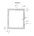
図4に示すように、本画像形成装置において記録材Pに余白無し印字を行う場合には、記録材Pに対する印字領域を決定するマスク領域Eを、塗り足し領域Bの分だけ記録材Pよりも大きな領域としている。塗り足し領域Bは、記録材Pの先端部、後端部、左端部、右端部について各々所定の長さET、EB、EL、ERの幅を有する。 As shown in FIG. 4, when printing without margins on the recording material P in the image forming apparatus, a mask area E for determining a printing area for the recording material P is set more than the recording material P by the amount of the additional area B. It is also a big area. The added area B has predetermined lengths ET, EB, EL, and ER for the front end, rear end, left end, and right end of the recording material P, respectively.
そして、塗り足し領域の部分までを含めた画像を感光ドラム上に形成し、これを記録材Pに転写して余白無し印字を達成している。 Then, an image including the part of the added area is formed on the photosensitive drum, and this is transferred to the recording material P to achieve marginless printing.
このような方法で画像形成を行うことで、次のようなばらつきが生じたとしても、常に記録材P上に良好な余白無し印字を行うことができる。それは、記録材Pが二次転写ニップ部を通過する際の、中間転写ベルト101上画像と記録材Pの相対位置関係に関する搬送方向(画像形成装置のプロセス方向)とこれと垂直な方向(画像形成装置の走査方向)のばらつきである。また、記録材P寸法に関するプロセス方向と走査方向のばらつきである。
By performing image formation by such a method, it is possible to always perform good marginless printing on the recording material P even if the following variations occur. That is, when the recording material P passes through the secondary transfer nip portion, the conveyance direction (process direction of the image forming apparatus) relating to the relative positional relationship between the image on the
また、二次転写時に記録材Pより外側にある塗り足し領域のトナーの一部は、二次転写ローラ102に付着することになる。この付着トナーは、記録材Pの裏汚れの原因となり得るため、二次転写ローラ102に当接している二次転写ローラクリーナ122で除去される。
In addition, a part of the toner in the added area outside the recording material P during the secondary transfer adheres to the
図5に示すように、二次転写部において二次転写工程を終えた記録材P上には、表面のみならず、端部を取り囲む周囲四辺部の紙こば面Paの一部においてもトナーtが転写されている。この記録材Pが、定着器103内に進入する際、定着ニップ部において、紙こば面上のトナーtaが未定着のままとなり、定着ローラ130及び加圧ローラ131表面上にオフセットする現象が発生する。このオフセットトナーが各ローラ表面に付着すると、記録材Pの表面及び裏面の汚れを引き起こす。そのため、定着ローラ130及び加圧ローラ131の表面には、それぞれクリーニングローラ132,133が当接されており、これらを用い、両ローラ表面に付着したトナーが回収される。
As shown in FIG. 5, on the recording material P that has been subjected to the secondary transfer process in the secondary transfer portion, toner is not only present on the surface but also on a part of the paper surface Pa on the four sides surrounding the end portion. t is transferred. When the recording material P enters the
ところが、上記構成の定着装置を使用し、余白無し印字動作を継続していると、各クリーニングローラ上のトナー付着量が増し、クリーニングローラ上のトナーが定着ローラや加圧ローラに逆流し、記録材の汚れを引き起こすという問題が生じることが懸念される。 However, if the fixing device configured as described above is used and the marginless printing operation is continued, the toner adhesion amount on each cleaning roller increases, and the toner on the cleaning roller flows backward to the fixing roller and the pressure roller, thereby recording. There is a concern that the problem of causing soiling of the material may occur.
これに対しては、次に示すようなクリーニング制御方法が開示されている(例えば、特許文献1参照)。それは、印字動作を一定枚数行った後に、定着装置を温度コントロールした状態で空回転動作させ、意図的にクリーニングローラ上のトナーを定着/加圧ローラに逆流させ、さらにクリーニング材を定着ニップ部に搬送し通過させるものである。このようにして、クリーニングローラ上に付着したトナーを再回収している。
しかしながら、上記クリーニング制御方法を、余白無し印字を行うことが可能な画像形成装置に適用する場合には、以下のような課題が生じることが懸念される。 However, when the cleaning control method is applied to an image forming apparatus capable of performing marginless printing, there is a concern that the following problems may occur.
すなわち、あるサイズの記録材を使用して余白無し印字を継続した場合、各クリーニングローラ上でトナーが付着する走査方向の領域幅は、通紙した記録材の幅に対して拡がりを持ったものとなる場合がある。これは、クリーニングローラ表面に付着したトナーが、各クリーニングローラと、定着ローラ又は加圧ローラで形成されるクリーニングニップ内の圧力の作用により、押し潰され走査方向に拡がるためである。 In other words, when printing without margins using a recording material of a certain size, the area width in the scanning direction where the toner adheres on each cleaning roller is wider than the width of the recording material that has passed through. It may become. This is because the toner adhering to the surface of the cleaning roller is crushed and spread in the scanning direction by the action of the pressure in the cleaning nip formed by each cleaning roller and the fixing roller or pressure roller.
一方で、余白無し印字動作中に記録材が定着装置内を搬送される際や、クリーニング制御実施中にクリーニング材が定着装置内を搬送される際には、定着装置と記録材或いはクリーニング材との間の相対位置関係に走査方向のばらつきが生じることもある。 On the other hand, when the recording material is conveyed in the fixing device during the marginless printing operation or when the cleaning material is conveyed in the fixing device during the cleaning control, the fixing device and the recording material or the cleaning material Variations in the scanning direction may occur in the relative positional relationship between the two.
このような状況で余白無し印字が行われた記録材と同一の幅を有するクリーニング材を通紙しクリーニング制御を行ったとしても、クリーニングローラ上に付着したトナーの一部を再回収することはできても、全てのトナーを再回収することはできない場合がある。 Even if a cleaning material having the same width as the recording material on which printing without margins is performed in this situation and the cleaning control is performed, a part of the toner adhering to the cleaning roller may not be recovered again. Even if it can, all the toner may not be collected again.
これは、定着装置内に残留したトナーが以降の印字動作において、記録材の汚れを引き起こすという余白無し印字時特有の問題である。 This is a problem peculiar to marginless printing in which the toner remaining in the fixing device causes the recording material to become dirty in the subsequent printing operation.
装置の最大用紙幅を持つ記録材で余白無し印字が行われた場合、各クリーニングローラ上で紙こばトナーが付着する走査方向の領域幅は最大通紙幅より大きくなる。 When marginless printing is performed with a recording material having the maximum sheet width of the apparatus, the area width in the scanning direction to which the paper dust toner adheres on each cleaning roller is larger than the maximum sheet passing width.
従って、前述した特許文献1に開示されているクリーニング制御を、クリーニング材として最大通紙幅の記録材を用いて行っても、定着/加圧ローラに逆流・付着させたオフセットトナーを完全に回収することはできないことが懸念される。
Therefore, even when the cleaning control disclosed in
従って、余白無し印字を行える記録材の最大幅は、装置の最大用紙幅よりも狭く設定し、通紙できるクリーニング材幅やクリーニングローラ幅を余白無し印字が可能な最大記録材幅より広くすれば良い。 Therefore, the maximum width of the recording material that can be printed without margins should be set narrower than the maximum paper width of the device, and the width of the cleaning material that can be passed through and the cleaning roller width should be wider than the maximum recording material width that can be printed without margins. good.
しかしながら、例えば、特許文献2に開示されているように、装置の最大用紙幅よりもクリーニングローラ幅を長く設定してしまった場合、以下のような問題が懸念される。
However, for example, as disclosed in
すなわち、クリーニングローラ上に付着したトナーが装置の最大用紙幅より外側まで広がってしまうことが考えられる。この状態でクリーニングローラ上のトナーを定着/加圧ローラに逆流させてクリーニング材に回収しようとすると、装置の最大用紙幅を有するクリーニング材を通紙しても装置の最大用紙幅より外側のトナーは定着/加圧ローラに残留してしまう。 That is, it is conceivable that the toner attached on the cleaning roller spreads outside the maximum sheet width of the apparatus. In this state, if the toner on the cleaning roller is caused to flow back to the fixing / pressurizing roller and collected on the cleaning material, the toner outside the maximum paper width of the device is passed even if the cleaning material having the maximum paper width of the device is passed. Remains on the fixing / pressure roller.
このようにして定着/加圧ローラの最大用紙幅外に付着したトナーを除去する手段はない。よって、これらのトナーが逆に通紙領域に入り込んで記録材を汚したり、ローラ上にトナーが固着した状態で装置が起動されることによって定着/加圧ローラが傷ついてしまう等の問題が懸念される。 There is no means for removing the toner adhering outside the maximum sheet width of the fixing / pressure roller in this way. Therefore, there is a concern that these toners may enter the paper passing area to contaminate the recording material, or the fixing / pressing roller may be damaged when the apparatus is started in a state where the toner is fixed on the roller. Is done.
また、余白がある印字を行う場合や、ジャムリカバリー時のクリーニングをクリーニングローラを用いて行うと、クリーニングローラに蓄積できるトナー量をすぐに越え、クリーニング不良が発生してしまうという問題も懸念される。 In addition, when printing with margins or when cleaning during jam recovery is performed using a cleaning roller, there is a concern that the amount of toner that can be accumulated on the cleaning roller will quickly exceed the amount of toner that will cause a cleaning failure. .
本発明は上記したような事情に鑑みてなされたものであり、余白無し印字を行うことのできる画像形成装置において、定着手段のクリーニング制御を良好に行い、記録材の汚れを防止することを目的とする。 SUMMARY OF THE INVENTION The present invention has been made in view of the above circumstances, and an object of the present invention is to satisfactorily perform cleaning control of a fixing unit and prevent contamination of a recording material in an image forming apparatus capable of performing marginless printing. And
上記目的を達成するために本発明にあっては、
記録材に未定着トナー画像を形成する画像形成手段と、
定着ニップ部を形成する回転体と、前記回転体に当接するクリーニング部材を有し、前記定着ニップ部で記録材を挟持搬送しつつ未定着トナー画像を記録材に定着する定着手段と、
を有し、記録材の全域に画像を形成する余白無し画像形成モードと、記録材の端部に余白を残して画像を形成する余白有り画像形成モードと、を実行できる画像形成装置において、
前記余白無し画像形成モードで使用できる最大幅の記録材の幅をW1、前記余白有り画像形成モードで使用できる最大幅の記録材の幅をW2、前記クリーニング部材の幅をWCP、とすると、W1<WCP<W2の関係を有することを特徴とする。
In order to achieve the above object, the present invention provides:
Image forming means for forming an unfixed toner image on a recording material ;
A rotating member that forms a fixing nip portion; and a fixing unit that fixes a non-fixed toner image on the recording material while sandwiching and conveying the recording material at the fixing nip portion, and a cleaning member that contacts the rotating member .
Anda no-margin image formation mode for forming an image on the entire area of the serial Rokuzai, in an image forming apparatus that can perform, and the margin image formation mode for forming an image, leaving a margin on the edge portion of the recording material,
Wherein the width of the recording material of the maximum width that can be used in no-margin image formation mode W1, and the width of the recording material of the maximum width that can be used in the the margin image formation mode W2, WCP the width of the cleaning member, that, W1 <characterized by having a relationship of WCP <W2.
本発明によれば、余白無し印字を行うことのできる画像形成装置において、定着手段のクリーニング制御を良好に行い、記録材の汚れを防止することが可能となる。 According to the present invention, in an image forming apparatus capable of performing marginless printing, it is possible to satisfactorily control the cleaning of the fixing unit and prevent the recording material from being stained.
以下に図面を参照して、この発明を実施するための最良の形態を例示的に詳しく説明する。ただし、この実施の形態に記載されている構成部品の寸法、材質、形状それらの相対配置などは、発明が適用される装置の構成や各種条件により適宜変更されるべきものであり、この発明の範囲を以下の実施の形態に限定する趣旨のものではない。 The best mode for carrying out the present invention will be exemplarily described in detail below with reference to the drawings. However, the dimensions, materials, shapes, and relative arrangements of the components described in this embodiment should be appropriately changed according to the configuration of the apparatus to which the invention is applied and various conditions. It is not intended to limit the scope to the following embodiments.
図1は、本発明の実施例1に係る画像形成装置Aの概略構成を示す断面図である。図2は、画像形成装置Aと画像送信装置との接続状態を示す概略図である。
FIG. 1 is a cross-sectional view illustrating a schematic configuration of an image forming apparatus A according to
本実施例に係る画像形成装置で使用可能な記録材は、幅320mm×長さ450mmのA3ノビサイズまでである。またプロセススピードは117mm/秒である。A4横送りの印字速度としては、24枚/分が可能である。 The recording material that can be used in the image forming apparatus according to the present embodiment is up to A3 Nobi size of 320 mm wide × 450 mm long. The process speed is 117 mm / second. A printing speed of A4 horizontal feed can be 24 sheets / minute.
本実施例の画像形成装置Aは、図2に示したように、画像送信装置としてのパソコン91とケーブル92を介して接続されている。画像データは、パソコン91からケーブル92を経由して、画像形成装置Aに送信される。
As shown in FIG. 2, the image forming apparatus A of the present embodiment is connected to a
画像形成装置Aは、記録材Pに対して、余白無しの印字を行うための余白無し印字モードと、通常の余白有りの印字を行うための余白有り印字モードと、による画像形成を行う機能を備えている。ここで、余白無し印字モードは、記録材の全域に画像を形成する第1の画像形成モードを構成している。余白有り印字モードは、記録材の端部に余白を残して画像を形成する第2の画像形成モードを構成している。 The image forming apparatus A has a function of performing image formation on the recording material P by a marginless printing mode for performing printing without margins and a printing mode with margins for performing printing with ordinary margins. I have. Here, the marginless printing mode constitutes a first image forming mode in which an image is formed on the entire area of the recording material. The printing mode with a margin constitutes a second image forming mode in which an image is formed while leaving a margin at the end of the recording material.
<画像形成装置の構成と動作について>
本実施例に係る画像形成装置Aは、4ドラム、中間転写方式のフルカラープリンタに構成されている。
<Configuration and operation of image forming apparatus>
The image forming apparatus A according to the present embodiment is configured as a four-drum, intermediate transfer type full-color printer.
図1に示すように、画像形成装置Aは、イエロー(Y),マゼンタ(M),シアン(C),ブラック(K)の4色の画像形成部(画像形成ステーション10)10a,10b,10c,10dを有している。さらに、中間転写体としての中間転写ベルト1を含む転写装置、及び定着手段としての定着装置3を有する。ここで、各画像形成ステーション10a〜10d及び転写装置は、画像形成手段を構成している。
As shown in FIG. 1, the image forming apparatus A includes four color image forming units (image forming stations 10) 10a, 10b, and 10c of yellow (Y), magenta (M), cyan (C), and black (K). , 10d. Further, the image forming apparatus includes a transfer device including the
各画像形成ステーション10a,10b,10c,10dは画像形成ユニットに構成され、それぞれ像担持体としての感光ドラム(ドラム状電子写真感光体)11a,11b,11c,11dが矢印方向に回転可能に設置されている。
Each of the
この感光ドラム11a,11b,11c,11dの外周表面上に、それぞれ感光ドラム表面を一様に帯電する一次帯電ローラ12a,12b,12c,12dが配置されている。そして、一次帯電ローラにより帯電された感光ドラム表面に対して、画像信号に対応して変調されたレーザ光を露光するレーザ露光器13a,13b,13c,13dが、一次帯電ローラに対して感光ドラム回転方向下流側に配置されている。
On the outer peripheral surfaces of the
さらに、レーザ露光器より感光ドラム回転方向下流側には、現像器14a,14b,14c,14dが配置される。現像器14a,14b,14c,14dは、レーザ露光により形成された感光ドラム表面上の各色の静電潜像を、対応する色のイエロー,マゼンタ,シアン,ブラックのトナー(現像剤)を用いて現像する。
Further, developing
感光ドラム11a,11b,11c,11dの中間転写ベルト1を挟んだ位置(転写位置)には、感光ドラムとともに一次転写部を形成する一次転写ローラ15a,15b,1
5c,15dが対向設置されている。この一次転写ローラ15a,15b,15c,15dには,一次転写電源としてそれぞれ一次転写電源16a,16b,16c,16dが接続され,それぞれ可変な一次転写電圧Vy,Vm,Vc,Vkが印加される。
5c and 15d are installed facing each other. Primary
中間転写ベルト1は、駆動ローラ1a,テンションローラ1b,二次転写対向ローラ1cの3本のローラに張架して設置され、各画像形成ステーション10a〜10dを縦貫して、感光ドラム11a〜11dに接触配置されている。中間転写ベルト1は、駆動ローラ1aにより図1に示す矢印方向に回転駆動される。
The
感光ドラム11a,11b,11c,11dの一次転写ローラ15a,15b,15c,15dの下流側には、ドラムクリーナ17a,17b,17c,17dが設置されている。また、中間転写ベルト1の表面には、ベルトクリーナ4が配置されている。
以上のように構成された画像形成装置の画像形成動作について、イエローの画像形成ステーション10aを例にして説明する。
The image forming operation of the image forming apparatus configured as described above will be described using the yellow
イエローステーション10aの感光ドラム11aは、アルミニウムの円筒体表面に光導電層を有している。そして、図1に示す矢印方向へ回転する過程で次のような動作が行われる。一次帯電ローラ12aにより表面を一様にマイナス帯電(帯電電位=−600V)され、次いでレーザ露光器13aにより画像露光が行われ(露光後の表面電位=−200V)、感光ドラム11aの表面に原稿のイエロー画像成分と対応した静電潜像が形成される。この潜像は、現像器14aによりマイナス帯電したイエロートナーを用いて現像され、潜像がイエロートナー像(現像剤像)として可視化される。
The
得られたイエロートナー像は、一次転写ローラ15aに一次転写電源16aから一次転写電圧を印加することによって、中間転写ベルト1上に一次転写される。転写後の感光ドラム11aは、表面に付着している転写残トナーがドラムクリーナ17aによって除去され、次の画像形成に供される。
The obtained yellow toner image is primarily transferred onto the
以上の画像形成動作を、各画像形成ステーション10a〜10dにおいて所定のタイミングを持って行い、感光ドラム11a〜11d上のトナー像をそれぞれの一次転写部で中間転写ベルト1上に順次重ねて一次転写する。
The above image forming operation is performed at a predetermined timing in each of the
フルカラーモードの場合は、中間転写ベルト1に対してイエロー,マゼンタ,シアン,ブラックの順でトナー像が順次転写され、単色や2〜3色モードの場合は、必要な色のトナー像が上記と同じ順で転写される。その後、中間転写ベルト1上の4色のトナー像は、中間転写ベルト1の図1に示す矢印方向の回動に伴い、二次転写ローラ2が中間転写ベルト1を挟んで接地された二次転写対向ローラ1cと当接することで構成された二次転写部(二次転写ニップ部)に移動される。
In the full color mode, the toner images are sequentially transferred to the
そして、給送ローラ9により所定のタイミングをもって供給された記録材P上に、二次転写ローラ2に二次転写電源21から二次転写電圧が印加されることにより一括して二次転写される。
Then, a secondary transfer voltage is applied to the
二次転写部を通過した未定着トナー像を載せた記録材Pは、定着装置3へと搬送され、加熱部材としての定着ローラ30と加圧部材としての加圧ローラ31とで構成される定着ニップ部で挟持搬送されることで加熱・加圧されて永久定着像となる。また、定着装置3から排出された記録材Pは、装置外の排出トレイ8に排出される。定着ローラ30と加圧ローラ31とは、定着装置3に回転可能に設けられている。
The recording material P on which the unfixed toner image that has passed through the secondary transfer portion is placed is conveyed to the fixing device 3 and is composed of a fixing
図3は、記録材保持手段としての記録材カセット5を示す概略斜視図である。以下、図3を用いて記録材カセット5について説明する。
FIG. 3 is a schematic perspective view showing a
記録材Pは、記録材カセット5内に一対の長手位置規制板52により、感光ドラム11a〜11d、中間転写ベルト1、定着ローラ30、加圧ローラ31、及びクリーニングローラ32,33と、長手方向の中心(走査方向の中心)が整列されて蓄積されている。
The recording material P includes a
これにより、記録材カセット5から搬送された記録材Pは、感光ドラム11a〜11d、中間転写ベルト1、定着ローラ30、加圧ローラ31及びクリーニングローラ32,33と、長手方向の中心が整列した状態で二次転写部、定着ニップ部に挿通される。
As a result, the recording material P conveyed from the
つまり、本実施例の画像形成装置はいわゆる中央基準構成となっている。ピックアップローラ対51により記録材カセット5から取り出された記録材Pは、給送装置6の搬送ローラ61と、給送ローラ9により、中間転写ベルト1上のトナー像に同期した所定のタイミングで二次転写部に挿通される。ここで、本実施例においては、ピックアップローラ対51と、給送装置6の搬送ローラ61と、給送ローラ9とは、後述する吐出しクリーニングモード時にクリーニング材を搬送する搬送手段を構成している。
That is, the image forming apparatus of this embodiment has a so-called central reference configuration. The recording material P taken out from the
図4は、記録材Pに対する塗り足し領域を示す図である。図5は、紙こばトナーの付着状態を示す図である。図6は、定着ローラ30及び加圧ローラ31の表面上のオフセットトナーを示す図である。
FIG. 4 is a diagram showing a region to be added to the recording material P. FIG. 5 is a diagram illustrating a state where paper dust toner is attached. FIG. 6 is a diagram illustrating offset toner on the surfaces of the fixing
本画像形成装置において記録材Pに余白無し印字を行う場合には、通常の余白有りの印字を行う場合に記録材P内の印字領域を決定するマスク領域Eが、図4に示すように、塗り足し領域Bの分だけ記録材Pよりも大きな領域とされる。ここで、本実施例において塗り足し領域Bは、図4に示すように、記録材Pの先端部ET、後端部EB、左端部EL、右端部ERについて各々2mmの幅を有する。 When performing printing without margins on the recording material P in this image forming apparatus, a mask area E that determines a printing area in the recording material P when performing printing with ordinary margins, as shown in FIG. The area B is larger than the recording material P by the added area B. Here, in the present embodiment, the additional region B has a width of 2 mm for each of the front end ET, the rear end EB, the left end EL, and the right end ER of the recording material P as shown in FIG.
そして、塗り足し領域Bの画像部分までを含めた画像を感光ドラム上に形成し、これを中間転写ベルト1を介して、記録材P上に転写して余白無し印字画像を得る。
Then, an image including the image portion of the added area B is formed on the photosensitive drum, and this is transferred onto the recording material P via the
なお、二次転写時に記録材Pより外側にある塗り足し領域のトナーの一部は、二次転写ローラ2上に付着することになる。この付着トナーは、二次転写ローラ2に当接している二次転写ローラクリーナ22で除去される。
Note that a part of the toner in the added area outside the recording material P during the secondary transfer adheres to the
一方で、二次転写部において二次転写工程を終えた記録材P上には、図5に示したように、表面のみならず、端部を取り囲む周囲四辺の裁断面部分である紙こば面Paの一部に対してもトナーtが転写されている。この記録材Pが定着装置3内に進入した場合、図6に示したように、定着ニップ部において紙こば面上のトナーtaが未定着のままとなり、定着ローラ30及び加圧ローラ31の表面上にオフセットする現象が発生することが懸念される。このオフセットトナーが各ローラ表面に付着すると、記録材Pの表面及び裏面の汚れを引き起こす。
On the other hand, on the recording material P that has been subjected to the secondary transfer process in the secondary transfer portion, as shown in FIG. 5, not only the surface but also a paper sheet that is a cut surface portion of the surrounding four sides surrounding the end portion. The toner t is also transferred to a part of the surface Pa. When the recording material P enters the fixing device 3, as shown in FIG. 6, the toner ta on the paper surface remains unfixed at the fixing nip portion, and the fixing
ここで、図7は本実施例における定着装置の一例を示したものである。 Here, FIG. 7 shows an example of a fixing device in the present embodiment.
上述の記録材汚れを防止するため、本実施例の定着装置の定着ローラ30及び加圧ローラ31には、それぞれ定着・加圧ローラに対して当接・離間を選択的に行える(接離可能な)回収手段としてのクリーニングローラ32,33が回転自在に備えられている。定着装置の構成、クリーニングローラ32及び33の当接離間機構については後述する。
In order to prevent the above-described recording material contamination, the fixing
これらクリーニングローラが定着・加圧ローラに対して当接することで、定着・加圧ローラ表面に付着したトナーをクリーニングローラ32,33上に回収する。この動作を、以下、定着・加圧ローラクリーニング動作と呼ぶ。
When these cleaning rollers come into contact with the fixing / pressure roller, the toner adhering to the surface of the fixing / pressure roller is collected on the
かくして、4色のトナー像が転写、定着された余白無しのフルカラー画像が記録材P上に得られる。 In this way, a full-color image without margins on which toner images of four colors are transferred and fixed is obtained on the recording material P.
<定着装置の詳細な説明>
ここで、図7を用いて本実施例に係る定着装置の構成について詳細な説明を行う。
<Detailed description of fixing device>
Here, the configuration of the fixing device according to the present embodiment will be described in detail with reference to FIG.
定着ローラ30は、外径46mm、厚み2mmの鉄の芯金上に、耐熱性を有しかつ硬度の低い厚み2mmのシリコーンゴム弾性層を設け、更にその上に厚み50umのPFA樹脂層を設けており、また、内部はヒータ94によって加熱されるようになっている。
The fixing
定着ローラ30の温度は、次のようにして、前記表面温度が所定の温度(例えば180℃程度)となるよう既知の制御方法でコントロールされる。すなわち、定着ローラ30に対して設けられた不図示の温度検知素子によって定着ローラ30の表面温度を検知させ、温度制御回路がヒータを断続的に作動させる。
The temperature of the fixing
一方、定着ローラ30に圧接し回転する加圧ローラ31は、外径44mm、厚み2mmの鉄の芯金上に、耐熱性を有しかつ硬度の低い厚み2mmのシリコーンゴム弾性層を設け、更にその上に厚み50umのPFA樹脂層を設けた構造をなしている。但し、内部にヒータは持たない。加圧ローラ31は両端に設けられたバネ81により、定着ローラ30に対して980Nの圧力で当接されている。
On the other hand, the
クリーニングローラ32,33は、アルミニウム製の金属ローラであり、外径は10mmである。また、それぞれ定着ローラ30と加圧ローラ31に対する当接/離間が選択可能である。当接時の加圧力は19.6Nである。
The cleaning
本実施例のクリーニングローラは、定着・加圧ローラクリーニング動作時と、吐出しクリーニング動作(吐出しクリーニングモード)時にのみ、定着・加圧ローラに対して当接する。ここで、定着・加圧ローラクリーニングとは、余白無し印字モードでの印字動作時(画像形成動作時)に、余白無し印字を行うことで定着・加圧ローラに付着する紙こばトナーを回収することをいう。また、吐出しクリーニングとは、クリーニングローラに蓄積したトナーを定着・加圧ローラ上に逆流させてクリーニング材により回収除去することをいう。これらのクリーニング動作は、制御手段としてのプリンタコントローラにより制御され実行されるものであり、クリーニング動作の詳細な説明は後述する。 The cleaning roller of this embodiment contacts the fixing / pressure roller only during the fixing / pressure roller cleaning operation and the discharge cleaning operation (discharge cleaning mode). Here, fixing and pressure roller cleaning refers to the collection of paper dust adhering to the fixing and pressure roller by performing marginless printing during the printing operation (image forming operation) in the marginless printing mode. To do. The discharge cleaning means that the toner accumulated on the cleaning roller is caused to flow backward on the fixing / pressure roller and collected and removed by a cleaning material. These cleaning operations are controlled and executed by a printer controller as a control means, and a detailed description of the cleaning operation will be described later.
図8は、クリーニングローラ32の形状を説明するための図である。
FIG. 8 is a view for explaining the shape of the cleaning
図8に示すように、クリーニングローラ32の両端部には回転軸部32cが設けられており、定着装置に設けられた不図示の軸受けに回転自在に支持されている。両端部の回転軸を除いたローラの有効長WCP(クリーニングローラ32が定着ローラ30に当接する部分の幅WCP)は305mmである。クリーニングローラ33はクリーニングローラ32と全く同じものを用いている。
As shown in FIG. 8,
<定着・加圧ローラクリーニング機構について>
ここで、本実施例の画像形成装置における、クリーニングローラ32,33の定着・加圧ローラクリーニング機構及び、その動作について図7を用いて説明する。
<Fixing and pressure roller cleaning mechanism>
Here, the fixing / pressure roller cleaning mechanism of the cleaning
クリーニングローラ32は、定着ローラ30の外周面(表面)に付着したオフセットトナーなどを清掃および回収する機能を有する。ここでは、クリーニングローラ32としてアルミ無垢のローラを用いている。クリーニングローラ33も同様である。
The cleaning
本実施例におけるクリーニングローラ32,33表面の中心線平均粗さをRa(c)とすると、0.20<Ra(c)≦0.50μmを満たすように設定されている。一方、定着ローラ10表面の中心線平均粗さをRa(s)とすると、0.05<Ra(s)≦0.20μmを満たすように設定されている。
When the center line average roughness of the surfaces of the cleaning
定着ローラ10の表面粗さRa(s)は、定着時に記録材上のトナーが定着ローラにオフセットしないように上記値に設定される。また、クリーニングローラ32,33の表面粗さRa(c)はRa(s)<Ra(c)の関係を満たし、良好なクリーニング性を確保できるように上記値に設定される。
The surface roughness Ra (s) of the fixing roller 10 is set to the above value so that the toner on the recording material is not offset to the fixing roller during fixing. Further, the surface roughness Ra (c) of the cleaning
定着ローラ30と並列に配置されたクリーニングローラ32は、第1リンクアーム70の一端に回転自在に保持されている。第1リンクアーム70は第1アーム軸76によりフレーム84に回動自在に支持され、第1バネ82によって定着ローラ30に対して所定の圧力で付勢されている。この付勢力によってクリーニングローラ32は定着ローラ30表面に圧接されている。
The cleaning
また、加圧ローラ31と並列に配置されたクリーニングローラ33は、第2リンクアーム71の一端に回転自在に保持されている。第2リンクアーム71は第2アーム軸77により加圧フレーム79に回動自在に支持され、第2バネ83によって加圧ローラ31に対して所定の圧力で付勢されている。この付勢力によってクリーニングローラ33は加圧ローラ31表面に圧接されている。
The cleaning
そして、第2リンクアーム71の他端には、カム軸72に固定保持されたクリーニング離間カム74と当接出来るようにピン78が形成されている。また、第1リンクアーム70の他端にはピン78に当接すべく当接部85が形成されている。
A
ここで、図9にクリーニングカム周辺の拡大断面図を示す。 Here, FIG. 9 shows an enlarged cross-sectional view around the cleaning cam.
クリーニング離間カム74はその外周面にカム面として、ピン78の外周面と接触してピン78を押し下げる大径部74aと、ピン78と接触しない小径部74bをそれぞれ2ヵ所ずつ有している。
The cleaning
クリーニングローラ32を有する第1リンクアーム70と、クリーニングローラ33を有する第2リンクアーム71と、カム軸72に設けられたクリーニング離間カム74とを備えるクリーニングローラ当接・離間機構において、カム軸72が時計方向へ回転する。すると、ピン78がクリーニング離間カム74の大径部74aで押し下げられて第2アーム軸77を中心に第2リンクアーム71を時計方向へ回動させる。これにより、クリーニングローラ33が加圧ローラ31表面から離間する。
In a cleaning roller abutting / separating mechanism including a
これと同時にピン78が第1リンクアーム70の当接部85に当接して第1リンクアーム70を第1アーム軸76を中心に反時計方向へ回動させる。これにより、クリーニングローラ32が定着ローラ30表面から離間する。
At the same time, the
なお、図9中の73は定着ローラ30と加圧ローラ31の当接離間を司る圧解除カムである。圧解除カム73は楕円形状をしており、クリーニング離間カム74と同軸となるように、カム軸72に固定されている。カム軸72が時計方向に回転し、圧解除カム73の
大径部が加圧フレーム79に設けられた圧解除コロ75を押し下げることにより、定着ローラ30と加圧ローラ31が離間される。
Note that
図10は、本実施例の定着装置における各ローラの当接離間状態を説明するための図である。 FIG. 10 is a diagram for explaining a contact and separation state of each roller in the fixing device of this embodiment.
カム軸72に対して圧解除カム73及びクリーニング離間カム74が図9のように固定されることによって、本実施例の装置では定着・加圧ローラの当接離間、クリーニングローラの当接離間に関して図10に示す状態I〜状態IIIの3状態を選択可能である。
By fixing the
本実施例では、余白無し印字が行われる場合のみ、上記機構によってクリーニングローラ32,33を定着ローラ30、加圧ローラ31それぞれに対して当接させ(状態I)、
定着ローラ30、加圧ローラ31上のオフセットトナーをクリーニングする。
In the present embodiment, the cleaning
The offset toner on the fixing
余白無し印字終了後は、再びクリーニングローラ32,33を定着ローラ30、加圧ローラ31それぞれから離間する(状態III)。余白有り印字時は状態IIで印字動作を行う
。
After printing without margins, the cleaning
<記録材サイズ、及びクリーニングローラの長さ規定>
図11は、記録材Pのサイズとクリーニングローラ32との長さ(幅)の関係を示す図である。
<Regulation of recording material size and cleaning roller length>
FIG. 11 is a diagram showing the relationship between the size of the recording material P and the length (width) of the cleaning
本実施例の画像形成装置では、記録材カセット5にセットされた記録材のサイズが既知の検知手段により検知される。
In the image forming apparatus of the present embodiment, the size of the recording material set in the
ここで、以下の説明において、記録材が画像形成装置内を搬送される際の、走査方向(記録材搬送方向に直交する方向(幅方向))のサイズを記録材の「幅」、プロセス方向(記録材搬送方向)のサイズを記録材の「長さ」とする。この場合、本画像形成装置で設定可能な記録材の幅は100mm〜320mm、長さは148mm〜450mmの範囲である。 Here, in the following description, when the recording material is conveyed in the image forming apparatus, the size in the scanning direction (direction perpendicular to the recording material conveyance direction (width direction)) is the “width” of the recording material, and the process direction The size in (recording material conveyance direction) is the “length” of the recording material. In this case, the width of the recording material that can be set in the image forming apparatus is in the range of 100 mm to 320 mm, and the length is in the range of 148 mm to 450 mm.
また、本実施例の画像形成装置においてユーザがパソコン91から画像データの送信を行う際、前述の余白無し印字モードで印字動作を行うか、余白有りモードで印字動作を行うかの設定を行える。余白無し印字モードを使用した場合は、記録材Pの全面に対して印字が行われた最終画像が得られ、余白有り印字モードを使用した場合には、記録材Pの先端部、後端部、左端部、右端部に5mm幅の余白が形成された最終画像が得られる。
In the image forming apparatus of the present embodiment, when the user transmits image data from the
ここで、本画像形成装置においては、余白無し印字モードにより動作可能な最大の記録材の幅W1は297mm(A4サイズ横送り又はA3サイズの記録材通紙時の幅に対応)である。これに対し、前述のようにクリーニングローラ32,33の有効長WCPは305mmであるから、定着ローラ30及び加圧ローラ31の表面上にオフセットした紙こばトナーを確実に回収できる。
Here, in this image forming apparatus, the maximum width W1 of the recording material that can be operated in the marginless printing mode is 297 mm (corresponding to the width at the time of A4 size lateral feeding or A3 size recording material passing). In contrast, since the effective length WCP of the cleaning
一方、余白有り印字モードにより動作可能な最大の記録材の幅W2(本実施例の画像形成装置に通紙可能な最大記録材幅)は320mm(A3ノビサイズの記録材通紙時の幅に対応)である。 On the other hand, the maximum width W2 of the recording material that can be operated in the margin printing mode (maximum recording material width that can be passed through the image forming apparatus of the present embodiment) corresponds to the width when passing through the recording material of A3 size. ).
本実施例の画像形成装置において前述の吐出しクリーニング制御実施時に使用されるクリーニング材として、幅WCLが320mm(=余白有り印字モードにより動作可能な最大の記録材幅W2)である白紙のA3ノビサイズの普通紙を用いる。このクリーニングを
記録材カセット5内にセットし、これを用いてクリーニングローラから定着/加圧ローラに吐出された紙こばトナーを確実に回収できる。
As the cleaning material used in the image forming apparatus according to the present embodiment when the above-described discharge cleaning control is performed, a white paper A3 Novi size having a width WCL of 320 mm (= the maximum recording material width W2 operable in the print mode with a margin). Use plain paper. This cleaning is set in the
これらを簡潔に表すと、図11に示されるように、
W1<WCP<W2
WCL=W2
の2つの関係が、本実施例の画像形成装置では満たされている。
These can be expressed simply as shown in FIG.
W1 <WCP <W2
WCL = W2
These two relationships are satisfied in the image forming apparatus of this embodiment.
ここで、クリーニングローラ32,33の有効長WCPを最大記録材幅W2より狭く設定した理由を説明する。
Here, the reason why the effective length WCP of the cleaning
クリーニングローラ32,33の有効長WCPを320mm(=W2)よりも長くした場合を考える。
Consider a case where the effective length WCP of the cleaning
この場合、余白無し印字時にクリーニングローラ上に付着した紙こばトナーが最大記録材幅W2より外側まで広がる可能性がある。 In this case, the paper dust toner adhering to the cleaning roller during marginless printing may spread outside the maximum recording material width W2.
クリーニングローラ上で最大記録材幅W2より外側まで広がったトナーを、前述の吐出しクリーニング制御により定着/加圧ローラに逆流させてクリーニング材で回収しようとしても次のようなことが懸念される。それは、装置の最大記録材幅W2をもつクリーニング材を通紙しても、装置の最大記録材幅W2より外側のトナーは定着/加圧ローラに残留してしまうことである。 Even if the toner that spreads outside the maximum recording material width W2 on the cleaning roller is caused to flow back to the fixing / pressurizing roller by the above-described discharge cleaning control and is collected by the cleaning material, the following may be caused. That is, even when a cleaning material having the maximum recording material width W2 of the apparatus is passed, toner outside the maximum recording material width W2 of the apparatus remains on the fixing / pressure roller.
このようにして定着/加圧ローラの最大記録材幅外に付着したトナーを除去する手段はない。よって、これらのトナーが逆に通紙領域に入り込んで記録材を汚したり、ローラ上にトナーが固着した状態で装置が起動されることによって定着/加圧ローラが傷ついてしまう等の問題が懸念される。 There is no means for removing the toner adhering outside the maximum recording material width of the fixing / pressure roller in this way. Therefore, there is a concern that these toners may enter the paper passing area to contaminate the recording material, or the fixing / pressing roller may be damaged when the apparatus is started in a state where the toner is fixed on the roller. Is done.
従って、本実施例の画像形成装置では、クリーニングローラ32,33の有効長WCPが最大記録材幅W2を超えないように設定されている。
Therefore, in the image forming apparatus of this embodiment, the effective length WCP of the cleaning
本実施例では、前述の関係に反する設定は、パソコン91上でユーザが行えないようになっている。つまり、記録材カセット5にセットされた記録材の幅が297mm以下である場合は、余白無し印字モードと余白有り印字モードのいずれを指定しても画像データの送信を行うことができる。しかし、記録材カセット5にセットされた記録材の幅が297mmより大きな幅である場合は、余白有り印字モードを指定しての画像データの送信しか行えない。
In the present embodiment, the setting contrary to the above-described relationship cannot be performed by the user on the
<余白無し印字における定着・加圧ローラクリーニング制御>
ここで、本実施例の画像形成装置における、余白無し印字時の定着・加圧ローラクリーニング制御について説明する。
<Fixing and pressure roller cleaning control for marginless printing>
Here, fixing and pressure roller cleaning control at the time of marginless printing in the image forming apparatus of the present embodiment will be described.
図12は、余白無し印字時の動作フローチャートを示す図である。 FIG. 12 is a diagram illustrating an operation flowchart for printing without margins.
パソコン91からのプリントリクエストを受信すると、余白無し印字が指定されているかを判断し(S1)、余白無し印字指定である場合には記録材サイズWが余白無し印字可能なサイズ(W≦297mm)であるかを確認する(S2)。余白無し印字が指定されていないと判断した場合には、余白有り印字動作を実行する(S15)。
When a print request is received from the
記録材サイズが余白無し印字可能なサイズであれば、余白無し印字動作を開始し、記録
材サイズが不適切な場合はエラーとする(S16)。
If the recording material size is a size that allows printing without margins, the marginless printing operation is started, and if the recording material size is inappropriate, an error is determined (S16).
余白無し印字動作を開始する場合、まずクリーニングローラ32,33を定着/加圧ローラに対して当接し(S3、前述した状態IIIから状態Iへ状態遷移する)、定着装置の回転駆動、プリント温調を開始する(S4)。その後、記録材がカセットから給送され(S6)、余白無しトナー像が形成された記録材が定着装置に通紙され、余白無しの永久画像が得られる(S7,S8)。
When the marginless printing operation is started, the cleaning
本実施例の画像形成装置では、余白無し印字が行われたページ数が、画像形成装置内に設けられたプリンタコントローラの余白無し印字ページ数カウンタによって、カウントされる(S5)。記録媒体としては、プリンタコントローラ内のメモリ(RAMや書き換え可能なROM等)が用いられる。余白無し印字動作の開始時に、上記余白無し印字ページ数カウンタの値Nが確認され、この値Nに余白無し印字を行ったページ数nを加算していく。 In the image forming apparatus of this embodiment, the number of pages on which marginless printing has been performed is counted by a marginless printing page number counter of a printer controller provided in the image forming apparatus (S5). As the recording medium, a memory (RAM, rewritable ROM, etc.) in the printer controller is used. At the start of the marginless printing operation, the value N of the marginless printing page number counter is confirmed, and the number n of pages for which marginless printing has been performed is added to this value N.
図12に示すフローチャート内の余白無し印字カウンタ加算値n決定処理(S9)では、以下のようにして加算値nを決定する。 In the marginless print counter addition value n determination process (S9) in the flowchart shown in FIG. 12, the addition value n is determined as follows.
図13に余白無し印字カウンタ加算値n決定処理のフローチャートを示す。 FIG. 13 shows a flowchart of the marginless print counter addition value n determination process.
ここでは、自動検知されたカセット5内の記録材の長さLを確認し(S21)、A4サイズ(横送り)の長さ210mmと比較する(S22)。記録材がA4サイズ以下の長さであれば加算値nを1とし(S23)、A4サイズより長ければ加算値nを2とする(S24)。
Here, the automatically detected length L of the recording material in the
記録材の長さLによりカウンタ加算値を変えるのは、記録材左右の紙こばトナーが、(記録材サイズが変わらない限り)常時クリーニングローラ上の同じ長手位置に付着し続けるからである。記録材の長さが長ければ、クリーニングローラ上の同じ長手位置に付着するトナー量が増えてクリーニング性の低下を促進するため、長い記録材に対しては加算値を大きく設定する。 The reason why the counter addition value is changed according to the length L of the recording material is that the paper dust toner on the left and right of the recording material always adheres to the same longitudinal position on the cleaning roller (unless the recording material size is changed). If the length of the recording material is long, the amount of toner adhering to the same longitudinal position on the cleaning roller is increased, and the deterioration of the cleaning property is promoted. Therefore, a large addition value is set for a long recording material.
このようにして加算値nが決定されると、これを加算した値が新たな余白無し印字ページ数カウンタの値Nとして更新される(S10)。 When the addition value n is determined in this way, the value obtained by adding the addition value n is updated as the value N of the new marginless print page number counter (S10).
その後、両面印字指定であれば(S13でYes)、不図示の自動両面機構を用いた既知の方法で記録材を反転させた後、再給送して記録材裏面に印字を行う(S14)。 Thereafter, if double-sided printing is specified (Yes in S13), the recording material is reversed by a known method using an automatic double-side mechanism (not shown), and then fed again to print on the back surface of the recording material (S14). .
両面印字の指定がなく(S13でNo)、新たなプリントリクエストを受信していなければ(S17でNo)、印字終了処理(後回転温調、回転停止)を行い、クリーニングローラを離間させる(S18〜20)。 If double-sided printing is not designated (No in S13) and no new print request has been received (No in S17), a print end process (post-rotation temperature adjustment, rotation stop) is performed, and the cleaning roller is separated (S18). ~ 20).
新たなプリントリクエストを受信していれば(S17でYes)、印字動作を続行する。 If a new print request has been received (Yes in S17), the printing operation is continued.
本実施例では、余白無し印字の終了前に余白あり印字のプリントリクエストを受信した場合、クリーニングローラを当接したまま余白あり印字を行う(余白無し印字ページ数カウンタの値Nにカウントされる)。 In the present embodiment, when a print request for printing with margins is received before the end of printing without margins, printing with margins is performed with the cleaning roller in contact (counted to the value N of the page number counter without margins). .
余白無し印字から余白あり印字への移行時間を省略するため、本実施例ではこのように処理を行うが、余白無し印字を終了させてから余白あり印字を開始しても良い。 In this embodiment, the processing is performed in this way in order to omit the transition time from marginless printing to printing with margins. However, printing with margins may be started after completion of marginless printing.
<吐出しクリーニング制御(吐出しクリーニングモード)>
上記余白無し印字動作において、余白無し印字ページ数カウンタの値Nが1k(1000)ページを超えると(S11でYes)、吐出しクリーニングの実行を促すメッセージが表示される(S12)。
<Discharge cleaning control (discharge cleaning mode)>
In the marginless printing operation, if the value N of the marginless printing page number counter exceeds 1k (1000) pages (Yes in S11), a message prompting execution of ejection cleaning is displayed (S12).
パソコン91上には、記録材カセット5内にクリーニング材として白紙のA3ノビサイズ(幅320mm×長さ450mm)の普通紙を一枚セットし、吐出しクリーニング制御を開始するためのパソコン操作を行うよう、メッセージが表示される。ユーザがこのメッセージに従うと、画像形成装置に吐出しクリーニング実行要求が送られ、クリーニングローラ上のトナーを、クリーニング材上に再回収するためのシーケンスが稼働する。
On the
図14は、吐出しクリーニング制御の動作フローチャートを示す図である。 FIG. 14 is a diagram illustrating an operation flowchart of the discharge cleaning control.
吐出しクリーニング実行要求を受信すると、記録材カセット5の記録材サイズがA3ノビサイズ(幅320mm×長さ450mm)であるかを確認する(S31,32)。ここで、S31を実行する制御手段と記録材カセット5の記録材のサイズを検出するセンサとは検出手段を構成し、S32を実行する制御手段は判断手段を構成している。
When the ejection cleaning execution request is received, it is confirmed whether the recording material size of the
記録材サイズが上記サイズであれば、吐出しクリーニング制御が開始される(実行可能となる)。 If the recording material size is the above size, ejection cleaning control is started (becomes executable).
記録材サイズが不適合であれば、エラーとする。そして、記録材カセット5内にクリーニング材として白紙のA3ノビサイズ(幅320mm×長さ450mm)の普通紙を一枚セットし、吐出しクリーニング制御を開始するためのパソコン操作を行うよう、再度メッセージが表示される(S44)。
An error occurs if the recording material size is incompatible. Then, a message is displayed again to set a sheet of plain A3 paper (width: 320 mm x length: 450 mm) as a cleaning material in the
吐出しクリーニング制御が開始されると、まずクリーニングローラ32,33を定着ローラ30、加圧ローラ31それぞれに対して当接させ(S33)、その後、制御温度(所定の温度状態)180℃で定着装置の空回転が60sec行われる(S34〜37)。このとき、クリーニングローラ上のトナーが下記原理により定着/加圧ローラ上へ吐出される。ここで、S33〜S37を実行する制御手段が、移動手段を構成している。
When the discharge cleaning control is started, the cleaning
クリーニングローラ32,33を定着ローラ30、加圧ローラ31に当接させて空回転を行うことにより、クリーニングローラ32,33はそれぞれ定着ローラ、加圧ローラとほぼ同じ温度まで昇温する。
By causing the cleaning
ここで、クリーニングローラ32と定着ローラ30に着目する。
Here, attention is paid to the cleaning
余白無し印字時は、
定着ローラ温度>クリーニングローラ温度、且つ、
定着ローラ表面粗さRa(s)<クリーニングローラ表面粗さRa(c)
であるので、定着ローラ上のオフセットトナーはクリーニングローラ上に回収される。
When printing without margins,
Fixing roller temperature> cleaning roller temperature, and
Fixing roller surface roughness Ra (s) <Cleaning roller surface roughness Ra (c)
Therefore, the offset toner on the fixing roller is collected on the cleaning roller.
しかしながら、上記空回転を行った場合は前述のように、
定着ローラ温度≒クリーニングローラ温度
となる。さらにクリーニングローラ32の表面は被覆層が無く、金属のままであるためトナーへの熱伝導性が定着ローラよりも高い。
However, when the idle rotation is performed, as described above,
The fixing roller temperature is equal to the cleaning roller temperature. Further, since the surface of the cleaning
これらの理由から、定着ローラ30とクリーニングローラ32との当接部では、定着ロ
ーラ30側のトナーの粘性がクリーニングローラ32側よりも高くなる。従って、トナーは定着ローラ表面の方に付着し易くなる。また、クリーニングローラ33と加圧ローラ31の間においてもこれと同じ現象が起こる。
For these reasons, the toner viscosity on the fixing
本実施例では、上記現象によりクリーニングローラ32,33に蓄積したトナーを定着ローラ30、加圧ローラ31に吐出すことができる。
In this embodiment, the toner accumulated on the
定着装置の空回転時間はタイマーでカウントされており、カウント値TRが60secに到達すると、記録材カセット5からクリーニング材としての記録材が給送される(S38)。このようにして、上述のように定着/加圧ローラ上に吐出されたトナーがクリーニング材上に回収される。 The idle rotation time of the fixing device is counted by a timer, and when the count value TR reaches 60 sec, a recording material as a cleaning material is fed from the recording material cassette 5 (S38). In this way, the toner discharged onto the fixing / pressure roller as described above is collected on the cleaning material.
クリーニング材が装置から排出されると(S39)、印字終了処理(後回転温調、回転停止)を行いクリーニングローラを離間させる(S40,41)。 When the cleaning material is discharged from the apparatus (S39), the printing end process (post-rotation temperature adjustment, rotation stop) is performed, and the cleaning roller is separated (S40, 41).
上記動作が終了すると、余白無し印字ページ数カウンタの値Nをリセット(N=0)して(S42)、吐出しクリーニングの終了を知らせるメッセージを表示する(S43)。 When the above operation is completed, the value N of the blank page number counter is reset (N = 0) (S42), and a message notifying the end of the discharge cleaning is displayed (S43).
このような吐出しクリーニングを定期的に行うことで、クリーニングローラに付着したトナーを回収するための機構を設けることなく、長期間に渡って良好なクリーニング性が保証できる。 By periodically performing such discharge cleaning, a good cleaning property can be ensured over a long period without providing a mechanism for collecting the toner adhering to the cleaning roller.
<JAM発生時のクリーニング>
本実施例の画像形成装置で画像形成動作中に記録材ジャム(紙詰まり)が発生した場合の、定着装置クリーニング(ジャム処理クリーニングモード)について説明する。
<Cleaning when JAM occurs>
The fixing device cleaning (jam processing cleaning mode) when a recording material jam (paper jam) occurs during the image forming operation of the image forming apparatus of this embodiment will be described.
ジャムが発生した場合、画像形成装置は緊急停止し、ユーザがジャム紙及び機内残留紙を取り除いてジャム処理を行う。ジャム処理後、定着ローラ、加圧ローラには多量のオフセットトナーが付着している。 When a jam occurs, the image forming apparatus stops urgently, and the user removes the jammed paper and the residual paper in the apparatus and performs jam processing. After the jam processing, a large amount of offset toner adheres to the fixing roller and the pressure roller.
本実施例では、このオフセットトナーを除去する際、クリーニングローラ32,33に回収するのではなく、クリーニング材を通紙して直接クリーニング材上にオフセットトナーを回収する。
In this embodiment, when the offset toner is removed, the offset toner is not collected on the
これは、ジャム時のオフセットトナーをクリーニングローラに回収すると、クリーニングローラ上のトナーがすぐに蓄積限界量を超えてしまい、余白無し印字中にトナーが定着、加圧ローラ上に逆流してしまうことが懸念されるからである。 This is because when the offset toner at the time of jam is collected on the cleaning roller, the toner on the cleaning roller immediately exceeds the accumulation limit amount, and the toner is fixed and flows backward onto the pressure roller during printing without margins. This is because of concern.
従って、本実施例でのジャムリカバリー時には、上述のようにクリーニング材上にオフセットトナーを直接回収させることにより、前述した吐出しクリーニングを行う頻度を低減させることができ、ユーザビリティの向上が可能となる。 Therefore, at the time of jam recovery in this embodiment, by collecting the offset toner directly on the cleaning material as described above, the frequency of performing the above-described discharge cleaning can be reduced, and usability can be improved. .
ジャム発生時の記録材幅をW、上記同様にクリーニング材の幅をWCLとすると、余白無し印字中にジャムが発生した場合(ジャム処理クリーニングモード時)、
W<WCL
である記録材をクリーニング材として用いる。
Assuming that the width of the recording material at the time of jam occurrence is W, and the width of the cleaning material is WCL as described above, if a jam occurs during printing without margins (in the jam processing cleaning mode),
W <WCL
This recording material is used as a cleaning material.
本実施例では、報知手段としてのパソコン91上に、
W<WCL
を満たす記録材をクリーニング材として使用するようにユーザに促すメッセージが表示さ
れる。
In the present embodiment, on the
W <WCL
A message prompting the user to use a recording material satisfying the condition as a cleaning material is displayed.
本実施例では、記録材カセット5内にセットされているA3ノビサイズ(幅320mm×長さ450mm)の普通紙をクリーニング材として用いる。
In this embodiment, plain paper of A3 size (width 320 mm × length 450 mm) set in the
このようにすることで、余白無し印字によって付着した紙こばトナーも含め、ジャム紙から定着、加圧ローラにオフセットしたトナーのすべてを確実に回収できる。 In this way, all of the toner fixed from the jammed paper and offset to the pressure roller can be reliably collected, including paper dust toner adhered by marginless printing.
一方、余白有り印字中にジャムが発生した場合、
W≦WCL
である記録材をクリーニング材として用いれば良い。
On the other hand, if a jam occurs during printing with margins,
W ≦ WCL
That is, the recording material may be used as a cleaning material.
本実施例では、ジャム発生時と同じサイズの紙(W=WCL)をクリーニング材として用いる。従って、印字時に選択されていた記録材カセットにセットされている記録材をそのままクリーニング材として通紙すればよい。 In this embodiment, the same size paper (W = WCL) as when a jam occurs is used as the cleaning material. Accordingly, the recording material set in the recording material cassette selected at the time of printing may be passed as a cleaning material as it is.
以上説明したように、本実施例では、余白無し印字モードで動作可能な最大の記録材幅W1、余白有り印字モードで動作可能な最大の記録材幅W2、クリーニングローラの有効長WCPの関係を
W1<WCP<W2
としている。さらに、余白無し印字実行時のみ、クリーニングローラによる定着、加圧ローラクリーニングを行っている。
As described above, in this embodiment, the relationship between the maximum recording material width W1 that can be operated in the marginless printing mode, the maximum recording material width W2 that can be operated in the printing mode with margins, and the effective length WCP of the cleaning roller. W1 <WCP <W2
It is said. Further, only when printing without margins is performed, fixing by the cleaning roller and pressure roller cleaning are performed.
これにより、余白無し印字動作により定着、加圧ローラに付着した紙こばトナーを確実にクリーニングローラで回収できる。 Accordingly, the paper toner attached to the fixing and pressure roller by the marginless printing operation can be reliably collected by the cleaning roller.
このような構成、動作を採用することにより、良好なクリーニング性を長期間維持できる画像形成装置を提供することが可能となる。 By adopting such a configuration and operation, it is possible to provide an image forming apparatus that can maintain good cleaning performance for a long period of time.
本実施例では、クリーニングローラによって定着、加圧ローラのクリーニングを行うのは余白無し印字時のみであり、ジャム発生時に定着、加圧ローラに付着したトナーはクリーニング材に直接回収している。従って、クリーニング手段の長寿命化が図れ、更に長期間に渡り記録材の汚れを確実に防止できる。 In this embodiment, the fixing roller and the pressure roller are cleaned by the cleaning roller only at the time of printing without margins, and the toner adhering to the fixing and pressure roller when a jam occurs is directly collected by the cleaning material. Therefore, the life of the cleaning means can be extended, and the recording material can be reliably prevented from being contaminated for a long period of time.
更に、ジャム発生時のクリーニングにおいて使用されるクリーニング材の幅は、印字モード(余白無し/有り)や印字時の記録材幅に応じて選択されるので、ジャムリカバリー後の記録材汚れが確実に防止できる。 In addition, the width of the cleaning material used for cleaning when a jam occurs is selected according to the printing mode (with or without margins) and the recording material width at the time of printing. Can be prevented.
なお、本実施例においては、吐出しクリーニング制御実施時に使用されるクリーニング材幅WCLは、
WCL=W2
を満たすものであったが、これに限るものではない。余白無し印字動作により定着、加圧ローラに付着した紙こばトナーをクリーニングローラで回収する効果を得るためには、クリーニング材幅WCLは、余白無し印字モードにより動作可能な最大の記録材の幅W1より大きいものであればよい。この場合には、上述した図14に示す吐出しクリーニング制御のS32で、
W1<WCL
が満たされると判断された場合に、吐出しクリーニング制御が実行されるようにするとよい。また、幅W2より大きいクリーニング材は、通常、記録材カセットに入らないため、クリーニング材幅WCLの上限を設定する必要はないが、幅W2より大きいクリーニング
材が記録材カセットに入ってしまった場合を考えて幅WCLの上限を設定しておいてもよい。この場合には、上述した図14に示す吐出しクリーニング制御のS32で、
W1<WCL≦W2
が満たされると判断された場合に、吐出しクリーニング制御が実行されるようにするとよい。
In the present embodiment, the cleaning material width WCL used during the discharge cleaning control is
WCL = W2
However, the present invention is not limited to this. The cleaning material width WCL is the maximum width of the recording material that can be operated in the marginless printing mode in order to obtain the effect of collecting the paper toner attached to the pressure roller by the marginless printing operation with the cleaning roller. It may be larger than W1. In this case, in S32 of the discharge cleaning control shown in FIG.
W1 <WCL
When it is determined that the above is satisfied, the discharge cleaning control may be executed. In addition, since the cleaning material larger than the width W2 does not normally enter the recording material cassette, there is no need to set the upper limit of the cleaning material width WCL. However, when the cleaning material larger than the width W2 enters the recording material cassette. In consideration of the above, an upper limit of the width WCL may be set. In this case, in S32 of the discharge cleaning control shown in FIG.
W1 <WCL ≦ W2
When it is determined that the above is satisfied, the discharge cleaning control may be executed.
本発明の実施例2に係る画像形成装置は、実施例1の画像形成装置と同様に、図1の構成を有する。また、画像形成装置の動作や構成部品等も、実施例1の画像形成装置と同様である。 The image forming apparatus according to the second embodiment of the present invention has the configuration shown in FIG. 1 as with the image forming apparatus according to the first embodiment. Further, the operation and components of the image forming apparatus are the same as those of the image forming apparatus of the first embodiment.
本実施例の特徴は、吐出しクリーニング制御実施時にクリーニング材として使用される記録材が、必ずしも、実施例1のように画像形成装置の余白有り印字モードで使用可能な最大幅の記録材ではない点である。すなわち、本実施例では、吐出しクリーニング制御実施時にクリーニング材として使用される記録材が、画像形成装置の余白無し印字モードによって印字動作が行われた記録材の使用履歴に応じて変更されることを特徴としている。 The feature of this embodiment is that the recording material used as the cleaning material at the time of performing the ejection cleaning control is not necessarily the maximum width recording material that can be used in the printing mode with margins of the image forming apparatus as in the first embodiment. Is a point. That is, in this embodiment, the recording material used as the cleaning material when performing the discharge cleaning control is changed according to the usage history of the recording material on which the printing operation has been performed in the marginless printing mode of the image forming apparatus. It is characterized by.
本実施例の画像形成装置においても、余白無し印字モードにより動作可能な最大の記録材の幅は297mm(A4サイズ横送り又はA3サイズの記録材通紙時の幅に対応)である。また、余白有り印字モードにより動作可能な最大の記録材の幅は320mm(A3ノビサイズの記録材通紙時の幅に対応)である。 Also in the image forming apparatus of the present embodiment, the maximum width of the recording material that can be operated in the marginless printing mode is 297 mm (corresponding to the width at the time of A4 size lateral feeding or A3 size recording material passing). In addition, the maximum width of the recording material that can be operated in the margin printing mode is 320 mm (corresponding to the width when the A3 Nobi size recording material is passed).
本実施例の画像形成装置においては、画像形成装置内のプリンタコントローラによって、余白無し印字が行われたページ数が実施例1と同じ方法でカウントされるのに加え、その際に使用された記録材の最大幅W1mが記憶される。ここで、プリンタコントローラは、記録材幅記憶手段を構成している。
In the image forming apparatus of this embodiment, the number of pages on which marginless printing has been performed is counted by the same method as in
余白無し印字がA4サイズ以下の記録材を使用して行われたときは1ページ、A4サイズ以上A3サイズ以下の記録材を使用して行われたときは2ページとカウントされる。 When printing without margins is performed using a recording material of A4 size or less, it is counted as one page, and when printing is performed using a recording material of A4 size or more and A3 size or less, it is counted as two pages.
このようにしてカウントされた余白無し印字ページ数が、累積で1kページに到達すると、パソコン91上には、次のようなメッセージが表示される。それは、記録材カセット5内にクリーニング材として、その幅WCLが余白無し印字中に使用された最大幅の記録材よりも幅広である白紙の普通紙を一枚セットし、吐出しクリーニング制御を開始するためのパソコン操作を行うことを促すメッセージである。
When the number of marginless print pages counted in this way reaches 1k pages in total, the following message is displayed on the
下表1に、余白無し印字中に使用された最大の記録材の幅と、クリーニング材として使用されるべき記録材としてメッセージ表示される記録材の種類と、の関係を示す。 Table 1 below shows the relationship between the maximum width of the recording material used during marginless printing and the type of recording material displayed as a message as the recording material to be used as the cleaning material.

ユーザがこのメッセージに従うと、クリーニングローラ上のトナーを、クリーニング材上に再回収するためのシーケンスが稼働する。 When the user follows this message, a sequence for recollecting the toner on the cleaning roller onto the cleaning material is activated.
図15は、本実施例における吐出しクリーニング制御の動作フローチャートを示す図である。 FIG. 15 is a diagram illustrating an operation flowchart of the discharge cleaning control in this embodiment.
吐出しクリーニング実行要求を受信すると、記録材カセット5の記録材サイズWと余白無し印字を行った記録材の最大幅W1mを比較する(S51〜53)。このとき、
W1m<W
であれば(S53でYes)、吐出しクリーニング制御が開始される。
When the ejection cleaning execution request is received, the recording material size W of the
W1m <W
If so (Yes in S53), the discharge cleaning control is started.
記録材サイズが不適合であれば、エラーとし、記録材カセット5内にクリーニング材として、その幅が
W1m<W
である白紙の普通紙を一枚セットし、吐出しクリーニング制御を開始するためのパソコン操作を行うよう、再度メッセージが表示される(S54)。その後の制御は実施例1と同じである。
If the recording material size is incompatible, an error occurs and the width of the
A message is displayed again to perform a personal computer operation for setting one sheet of plain white paper and starting discharge control (S54). The subsequent control is the same as in the first embodiment.
以上のように、本実施例の画像形成装置においては、
W1m<WCL
なる関係が成り立っている。
As described above, in the image forming apparatus of this embodiment,
W1m <WCL
The relationship is established.
従って、本実施例では、次のような場合であっても、余白無し印字中に使用された最大幅の記録材よりも幅広のクリーニング材を用いてクリーニング制御を行うことで、クリー
ニングローラ上に付着した全トナーを確実に再回収することができる。それは余白無しの印字が可能な幅の記録材を用いて余白無しの印字動作を継続し、各クリーニングローラにより回収されたトナーのクリーニングローラ上での付着領域の幅が、クリーニングニップ内の圧力の作用で、前記記録材の幅に対して拡がっていた場合である。
Therefore, in this embodiment, even in the following cases, the cleaning control is performed using the cleaning material wider than the maximum width recording material used during the marginless printing, so that the cleaning roller is placed on the cleaning roller. All the adhered toner can be reliably recovered again. It continues the printing operation without margin using a recording material having a width capable of printing without margin, and the width of the adhesion area on the cleaning roller of the toner collected by each cleaning roller is the pressure of the pressure in the cleaning nip. This is a case where it has expanded with respect to the width of the recording material.
また、余白無し印字動作中、次のようなばらつきが生じていたとしても、上述の設定が満たされている限り、クリーニング制御によってクリーニングローラ上に付着した全トナーを確実に再回収することができる。それは、前記記録材が定着装置内を搬送される際の定着装置との相対位置関係に生じる、走査方向のばらつき(位置ズレ)である。また、それは、前記クリーニング材を用いてクリーニング制御を実施中、前記クリーニング材が定着装置内を搬送される際の定着装置との相対位置関係に生じる、走査方向のばらつき(位置ズレ)である。また、それは、余白無し印字を行う前記記録材や、クリーニング制御を行う前記クリーニング材の寸法自体に生じる、幅のばらつきである。 Also, even if the following variation occurs during the marginless printing operation, as long as the above setting is satisfied, all the toner adhering to the cleaning roller can be reliably recovered by the cleaning control. . This is a variation (positional deviation) in the scanning direction that occurs in a relative positional relationship with the fixing device when the recording material is conveyed in the fixing device. Further, this is a variation (positional deviation) in the scanning direction that occurs in the relative positional relationship with the fixing device when the cleaning material is conveyed through the fixing device during the cleaning control using the cleaning material. It is also a variation in width that occurs in the dimensions of the recording material that performs printing without margins and the cleaning material that performs cleaning control.
また、クリーニング制御実施時に使用されるクリーニング材の種類の選択範囲が広がり、ユーザがクリーニング材を準備する上での負担が軽減される。 In addition, the selection range of the type of cleaning material used when performing the cleaning control is expanded, and the burden on the user when preparing the cleaning material is reduced.
以上説明したように本実施例では、使用される記録材とクリーニング材の幅の関係が、余白無し印字モードでの使用履歴のある最大の記録材幅をW1m、クリーニング制御で使用されるクリーニング材の幅をWCLとすると、
W1m<WCL
と設定されている。すなわち、クリーニング材幅WCLは余白無し印字時に用いられた記録材幅に応じて決定され、クリーニングローラ上のトナーをすべて回収可能な幅とされる。
As described above, in this embodiment, the width of the recording material to be used and the width of the cleaning material is set to W1 m, which is the maximum recording material width that has been used in the marginless printing mode, and the cleaning material used in the cleaning control. If the width of is WCL,
W1m <WCL
Is set. That is, the cleaning material width WCL is determined in accordance with the recording material width used during marginless printing, and is a width capable of collecting all the toner on the cleaning roller.
これにより、画像形成装置の余白有り印字モードで使用可能な最大幅の記録材をクリーニング材として使用せずとも、吐出しクリーニング制御によりクリーニングローラ上に付着したトナーを確実に再回収し、記録材の汚れを防止することができる。 As a result, the recording material having the maximum width that can be used in the printing mode with margins of the image forming apparatus is used as a cleaning material, and the toner adhered to the cleaning roller is reliably recovered again by the discharge cleaning control. Can prevent dirt.
なお、本実施例に係る画像形成装置も実施例1に係る画像形成装置と同様の構成を備えるものである。すなわち、余白無し印字モードで動作可能な最大の記録材幅W1、余白有り印字モードで動作可能な最大の記録材幅W2、クリーニングローラの有効長WCPの関係が、
W1<WCP<W2
である。さらに、余白無し印字実行時のみクリーニングローラによる定着、加圧ローラクリーニングを行っている。
Note that the image forming apparatus according to the present embodiment also has the same configuration as the image forming apparatus according to the first embodiment. That is, the relationship between the maximum recording material width W1 operable in the marginless printing mode, the maximum recording material width W2 operable in the marginal printing mode, and the effective length WCP of the cleaning roller is as follows.
W1 <WCP <W2
It is. Furthermore, fixing and cleaning with a pressure roller are performed only when printing without margins is performed.
従って、実施例1と同様に、良好なクリーニング性を長期間維持できる画像形成装置を提供することが可能である。 Therefore, as in the first embodiment, it is possible to provide an image forming apparatus that can maintain good cleaning properties for a long period of time.
図16は、本発明の実施例3に係る画像形成装置を示す概略断面図である。 FIG. 16 is a schematic sectional view showing an image forming apparatus according to Embodiment 3 of the present invention.
本実施例の画像形成装置A’においては、実施例1で述べた記録材カセットを複数個有する以外は、実施例1の画像形成装置Aと同様の構成であり、同様の構成部分については同一の符号を付して、その説明は省略する。 The image forming apparatus A ′ according to the present embodiment has the same configuration as the image forming apparatus A according to the first embodiment except that a plurality of recording material cassettes described in the first embodiment are provided. The description is abbreviate | omitted and the description is abbreviate | omitted.
本実施例の画像形成装置A’は、記録材保持手段として記録材カセット5に加え、記録材カセット5α、記録材カセット5β、記録材カセット5γを有する。各記録材カセットの構成は、図3で示した構成と同様である。
The image forming apparatus A 'according to the present exemplary embodiment includes a recording material cassette 5α, a recording material cassette 5β, and a recording material cassette 5γ in addition to the
記録材Pは各記録材カセット内のそれぞれ一対の長手位置規制板により、感光ドラム11a〜11d、中間転写ベルト1、定着ローラ30、加圧ローラ31、クリーニングローラ32,33と長手中心が整列されて蓄積されている。これにより、各記録材カセットから取り出された記録材Pは、感光ドラム11a〜11d、中間転写ベルト1、定着ローラ30、加圧ローラ31、クリーニングローラ32,33と長手中心が整列した状態で二次転写部、定着ニップ部に挿通される。つまり、本実施例の画像形成装置も中央基準構成となっている。
The longitudinal center of the recording material P is aligned with the
各記録材カセットに付属のピックアップローラ対51,51α,51β,51γにより各記録材カセットから取り出された記録材Pは、給送装置6の搬送ローラ61,61α,61β,61γと、給送ローラ9により、所定のタイミングで二次転写部に挿通される。所定のタイミングとは、中間転写ベルト1上のトナー像に同期したタイミングである。
The recording material P taken out from each recording material cassette by the pick-up
ここで、本実施例の画像形成装置における特徴について述べる。 Here, characteristics of the image forming apparatus according to the present embodiment will be described.
本実施例の画像形成装置においては、各記録材カセット内にセットされている記録材のサイズ(幅)を自動的に判別するための検出手段として不図示の(機械的或いは光学的な)機構が備えられている。 In the image forming apparatus of this embodiment, a mechanism (not shown) (mechanical or optical) as a detection means for automatically determining the size (width) of the recording material set in each recording material cassette Is provided.
上記機構により得られたサイズ情報は、画像形成装置内のプリンタコントローラによって記憶される。いずれの記録材カセットに関しても、設定可能な記録材の幅は100mm〜320mm、長さは148mm〜450mmの範囲である。 The size information obtained by the above mechanism is stored by a printer controller in the image forming apparatus. For any recording material cassette, the width of the recording material that can be set is in the range of 100 mm to 320 mm, and the length is in the range of 148 mm to 450 mm.
そして、パソコン91から画像データの送信を行う際、使用する記録材(記録材カセット)の指定と、余白無し又は余白有りの印字モードの指定を行えるが、さらに本画像形成装置においては、次のような決定がなされる。すなわち、プリンタコントローラにおいて、記憶された各記録材カセットにセットされた記録材サイズの情報に基づき、記録材カセット毎にどの印字モードが指定可能か、が決定される。ここで、どの印字モードが指定可能かが決定されるとは、余白無し印字モードによる印字動作の可否と、余白有り印字モードによる印字動作の可否とが決定されることをいう。また、プリンタコントローラは、記録材幅記憶手段及び決定手段を構成している。
When transmitting image data from the
また、実施例1では、吐出しクリーニング制御実施時に、ユーザが所定サイズのクリーニング材を記録材カセットにセットし、その後パソコン91上でクリーニング制御を開始するためのパソコン操作を行うことで制御が開始される構成であった。これに対し本実施例の画像形成装置では、吐出しクリーニング制御時に使用されるクリーニング材として、ある一つの記録材カセットにセットされた記録材が自動的に選択され、制御開始時にはそれが自動的に使用される。
In the first embodiment, when the discharge cleaning control is performed, the user sets a cleaning material of a predetermined size in the recording material cassette, and then starts the personal computer operation on the
以下に、例を述べる。 An example is described below.
表2には、記録材カセット5にはA3サイズ、記録材カセット5αにはA4横送りサイズ、カセット5βにはA3フルブリードサイズ、カセット5γにはA3ノビサイズの記録材がそれぞれセットされているケースを示す。ここで、A3サイズの記録材の幅は297mm、A4横送りサイズの記録材の幅は297mm、A3フルブリードサイズの記録材の幅は312mm、A3ノビサイズの記録材は幅320mm×長さ450mmである。
In Table 2, the
この場合、ユーザがパソコン91上で記録材カセット5、記録材カセット5αを指定して画像データを送信する場合は、余白有り印字、余白無し印字の何れのモードも指定可能である。一方で、記録材カセット5β、記録材カセット5γを指定して画像データを送信する場合には、余白無し印字のモードの指定は不可能で、余白有り印字のモードの指定のみが可能である。
In this case, when the user designates the
ここで、各記録材カセットにセットされた記録材を任意の配分で使用しながら印字動作が継続された場合、実施例1同様、プリンタコントローラによって余白無し印字が行われたページ数がカウントされ、吐出しクリーニング制御の実施タイミングが決定される。 Here, when the printing operation is continued while using the recording material set in each recording material cassette in an arbitrary distribution, the number of pages on which marginless printing is performed by the printer controller is counted as in the first embodiment. The execution timing of the discharge cleaning control is determined.
この際、クリーニング材としては、記録材カセット5β又は記録材カセット5γにセットされた記録材が使用可能であるが、本例では記録材カセット5γにセットされた記録材が自動的に搬送され使用される。 At this time, the recording material set in the recording material cassette 5β or the recording material cassette 5γ can be used as the cleaning material, but in this example, the recording material set in the recording material cassette 5γ is automatically conveyed and used. Is done.
つまり、本例では、上述した実施例のように、ユーザが記録材カセット内にクリーニング材をセットしクリーニング制御を開始するためのパソコン操作を行わなくても、記録材カセット5γ内にセットされた記録材がクリーニング材として自動的に搬送される。そして、吐出しクリーニング制御が実施される。 That is, in this example, as in the above-described embodiment, the user sets the cleaning material in the recording material cassette and does not perform the personal computer operation for starting the cleaning control. The recording material is automatically conveyed as a cleaning material. Then, discharge cleaning control is performed.
クリーニング材として用いられる記録材がセットされた記録材カセットを、上記のように自動選択する以外の動作については、上述した実施例でのフローと同じである。 The operations other than automatically selecting the recording material cassette in which the recording material used as the cleaning material is set as described above are the same as those in the above-described embodiment.
表3には、記録材カセット5にはLETTER横送りサイズ、記録材カセット5αにはA4横送りサイズ、カセット5βにはA4縦送りサイズ、カセット5γにはB4サイズの記録材がそれぞれセットされているケースを示す。ここで、LETTER横送りサイズの記録材の幅は279mm、A4横送りサイズの記録材の幅は297mm、A4縦送りサイズの記録材の幅は210mm、B4サイズの記録材の幅は257mmである。
In Table 3, the
この場合、ユーザがパソコン91上で記録材カセット5、記録材カセット5β、記録材カセット5γを指定して画像データを送信する場合は、余白有り印字、余白無し印字の何れのモードも指定可能である。一方で、記録材カセット5αを指定して画像データを送信する場合には、余白無し印字のモードの指定は不可能で、余白有り印字のモードの指定のみが可能である。
In this case, when the user designates the
本ケースにおいては、各記録材カセットにセットされた記録材を任意の配分で使用しながら印字動作が継続された場合、所定タイミングにて、記録材カセット5αにセットされた記録材が自動的に搬送され、クリーニング制御が実施される。 In this case, when the printing operation is continued while using the recording material set in each recording material cassette in an arbitrary distribution, the recording material set in the recording material cassette 5α is automatically set at a predetermined timing. It is transported and cleaning control is performed.
上記何れのケースにおいても、使用される記録材とクリーニング材の幅の関係が、次のような関係を満たす。すなわち、余白無し印字モードで使用される最大の記録材の幅をW1t、余白有り印字モードで使用される最大の記録材の幅をW2t、クリーニング制御で使用されるクリーニング材の幅をWCLtとすると、
W1t<W2t=WCLt
を満たす。
In any of the above cases, the relationship between the recording material used and the width of the cleaning material satisfies the following relationship. That is, the width of the largest recording material used in the marginless printing mode is W1t, the width of the largest recording material used in the printing mode with margins is W2t, and the width of the cleaning material used in the cleaning control is WCLt. ,
W1t <W2t = WCLt
Meet.
従って、各記録材カセットにセットされた記録材を任意の配分で使用しながら印字動作が継続されたとしても、次のような制御を実施することで、良好なクリーニングを行い、記録材の汚れを防止することができる。すなわち、本ケースでは、所定タイミングにおいて所定の記録材カセットよりクリーニング材としての記録材を自動的に搬送しクリーニング制御を実施することで、良好なクリーニングを行い、記録材の汚れを防止することができるものである。 Therefore, even if the printing operation is continued while using the recording material set in each recording material cassette in an arbitrary distribution, the following control is performed to perform good cleaning, and the recording material becomes dirty. Can be prevented. That is, in this case, a recording material as a cleaning material is automatically conveyed from a predetermined recording material cassette at a predetermined timing and cleaning control is performed, so that good cleaning can be performed and contamination of the recording material can be prevented. It can be done.
また、クリーニング制御実施時にユーザがクリーニング材を記録材カセットにセットしなければならない煩わしさも解消される。 Further, the troublesomeness that the user has to set the cleaning material in the recording material cassette when performing the cleaning control is also eliminated.
以上説明したように、本実施例の画像形成装置は、複数の記録材カセットを有している。そして、各記録材カセットにセットされた記録材の幅情報を元に、各記録材カセットにセットされた記録材を使用して、余白無し印字モードでの印字動作が可能か否か、余白有り印字モードでの印字動作が可能か否かを決定することができる。 As described above, the image forming apparatus of this embodiment has a plurality of recording material cassettes. Based on the width information of the recording material set in each recording material cassette, whether or not the printing operation in the marginless printing mode is possible using the recording material set in each recording material cassette, there is a margin. It is possible to determine whether or not the printing operation in the printing mode is possible.
そして、吐出しクリーニング制御実施時に、自動的に使用される記録材がセットされた
記録材カセットが決定される。すなわち、余白無し印字モードでの印字動作が否であって余白有り印字モードでの印字動作が可と決定された記録材カセットが決定され、この記録材カセットが複数ある場合には、それらのうち最大幅の記録材を保持する記録材カセットが決定される。
Then, when the ejection cleaning control is performed, a recording material cassette in which a recording material to be used automatically is set is determined. That is, a recording material cassette that is determined not to be capable of printing in the marginless printing mode and is allowed to perform the printing operation in the marginal printing mode is determined, and when there are a plurality of recording material cassettes, The recording material cassette that holds the maximum width recording material is determined.
これにより、クリーニングローラ上に付着したトナーを確実に再回収し、記録材の汚れを防止することができる。さらには、吐出しクリーニング制御実施時にユーザがクリーニング材を記録材カセットにセットしなければならない煩わしさを解消し、画像形成装置使用に際するユーザの利便性も高めることもできる。 As a result, the toner adhering to the cleaning roller can be reliably recovered again and the recording material can be prevented from being stained. Furthermore, it is possible to eliminate the inconvenience that the user has to set the cleaning material in the recording material cassette when performing the discharge cleaning control, and the convenience of the user when using the image forming apparatus can be improved.
なお、本実施例に係る画像形成装置も実施例1に係る画像形成装置と同様の構成を備えるものである。すなわち、余白無し印字モードで動作可能な最大の記録材幅W1、余白有り印字モードで動作可能な最大の記録材幅W2、クリーニングローラの有効長WCPの関係が、
W1<WCP<W2
である。さらに、余白無し印字実行時のみクリーニングローラによる定着、加圧ローラクリーニングを行うものである。
Note that the image forming apparatus according to the present embodiment also has the same configuration as the image forming apparatus according to the first embodiment. That is, the relationship between the maximum recording material width W1 operable in the marginless printing mode, the maximum recording material width W2 operable in the marginal printing mode, and the effective length WCP of the cleaning roller is as follows.
W1 <WCP <W2
It is. Furthermore, fixing with a cleaning roller and pressure roller cleaning are performed only when marginless printing is performed.
従って、実施例1と同様に、良好なクリーニング性を長期間維持できる画像形成装置を提供することが可能である。 Therefore, as in the first embodiment, it is possible to provide an image forming apparatus that can maintain good cleaning properties for a long period of time.
3 定着装置
10 画像形成ステーション
11 感光ドラム
30 定着ローラ
31 加圧ローラ
32,33 クリーニングローラ
P 記録材
3 Fixing device 10 Image forming station 11
Claims (4)
定着ニップ部を形成する回転体と、前記回転体に当接するクリーニング部材を有し、前記定着ニップ部で記録材を挟持搬送しつつ未定着トナー画像を記録材に定着する定着手段と、
を有し、記録材の全域に画像を形成する余白無し画像形成モードと、記録材の端部に余白を残して画像を形成する余白有り画像形成モードと、を実行できる画像形成装置において、
前記余白無し画像形成モードで使用できる最大幅の記録材の幅をW1、前記余白有り画像形成モードで使用できる最大幅の記録材の幅をW2、前記クリーニング部材の幅をWCP、とすると、W1<WCP<W2の関係を有することを特徴とする画像形成装置。 Image forming means for forming an unfixed toner image on a recording material ;
A rotating member that forms a fixing nip portion; and a fixing unit that fixes a non-fixed toner image on the recording material while sandwiching and conveying the recording material at the fixing nip portion, and a cleaning member that contacts the rotating member .
Anda no-margin image formation mode for forming an image on the entire area of the serial Rokuzai, in an image forming apparatus that can perform, and the margin image formation mode for forming an image, leaving a margin on the edge portion of the recording material,
Wherein the width of the recording material of the maximum width that can be used in no-margin image formation mode W1, and the width of the recording material of the maximum width that can be used in the the margin image formation mode W2, WCP the width of the cleaning member, that, W1 An image forming apparatus having a relationship of <WCP <W2.
使用するクリーニングシートより小さな幅の記録材に制限することを特徴とする請求項1に記載の画像形成装置。 The apparatus can execute a cleaning mode in which the toner attached to the cleaning member is moved to the rotating body and the cleaning sheet is passed through the fixing nip portion to collect the toner with the cleaning sheet. Among the recorded recording materials, the recording material having the maximum width is set as the cleaning sheet used in the cleaning mode, and the recording material having the maximum width that can be set in the marginless image forming mode is set in the cleaning mode.
2. The image forming apparatus according to claim 1 , wherein the recording material is limited to a recording material having a width smaller than that of the cleaning sheet to be used .
Priority Applications (1)
| Application Number | Priority Date | Filing Date | Title |
|---|---|---|---|
| JP2008007153A JP5106141B2 (en) | 2008-01-16 | 2008-01-16 | Image forming apparatus and image forming apparatus cleaning method |
Applications Claiming Priority (1)
| Application Number | Priority Date | Filing Date | Title |
|---|---|---|---|
| JP2008007153A JP5106141B2 (en) | 2008-01-16 | 2008-01-16 | Image forming apparatus and image forming apparatus cleaning method |
Publications (3)
| Publication Number | Publication Date |
|---|---|
| JP2009169106A JP2009169106A (en) | 2009-07-30 |
| JP2009169106A5 JP2009169106A5 (en) | 2011-03-03 |
| JP5106141B2 true JP5106141B2 (en) | 2012-12-26 |
Family
ID=40970341
Family Applications (1)
| Application Number | Title | Priority Date | Filing Date |
|---|---|---|---|
| JP2008007153A Active JP5106141B2 (en) | 2008-01-16 | 2008-01-16 | Image forming apparatus and image forming apparatus cleaning method |
Country Status (1)
| Country | Link |
|---|---|
| JP (1) | JP5106141B2 (en) |
Families Citing this family (3)
| Publication number | Priority date | Publication date | Assignee | Title |
|---|---|---|---|---|
| JP6231916B2 (en) | 2013-05-30 | 2017-11-15 | シャープ株式会社 | Image forming apparatus |
| JP2015018216A (en) | 2013-06-13 | 2015-01-29 | シャープ株式会社 | Image forming apparatus |
| JP7360617B2 (en) | 2019-10-07 | 2023-10-13 | 株式会社リコー | Image forming device |
Family Cites Families (7)
| Publication number | Priority date | Publication date | Assignee | Title |
|---|---|---|---|---|
| JP3292568B2 (en) * | 1993-11-01 | 2002-06-17 | 株式会社リコー | Image forming device |
| JPH09160420A (en) * | 1995-12-13 | 1997-06-20 | Toshiba Corp | Fixing device |
| JP2002207373A (en) * | 2001-01-09 | 2002-07-26 | Canon Inc | Image forming device |
| JP2003057985A (en) * | 2001-08-09 | 2003-02-28 | Canon Inc | Image forming apparatus |
| JP4307128B2 (en) * | 2003-04-04 | 2009-08-05 | キヤノン株式会社 | Laser printer |
| JP2007078788A (en) * | 2005-09-12 | 2007-03-29 | Oki Data Corp | Image forming apparatus and image print system |
| JP4802709B2 (en) * | 2005-12-28 | 2011-10-26 | セイコーエプソン株式会社 | Fixing device, image forming apparatus |
-
2008
- 2008-01-16 JP JP2008007153A patent/JP5106141B2/en active Active
Also Published As
| Publication number | Publication date |
|---|---|
| JP2009169106A (en) | 2009-07-30 |
Similar Documents
| Publication | Publication Date | Title |
|---|---|---|
| JP4481259B2 (en) | Image forming apparatus, temperature control method for fixing apparatus, temperature control program, and recording medium therefor | |
| US7636527B2 (en) | Fuser apparatus, image forming apparatus including the fuser apparatus, and fuser controlling method | |
| US20070158895A1 (en) | Image forming apparatus and image forming method, and program | |
| JP2009271517A (en) | Image forming apparatus and fixing portion cleaning method | |
| JP2008122512A (en) | Image forming apparatus | |
| JP2018022001A (en) | Image forming apparatus | |
| JP2008009097A (en) | Fixing device and image forming apparatus equipped therewith | |
| JP5106141B2 (en) | Image forming apparatus and image forming apparatus cleaning method | |
| JP4509138B2 (en) | Image forming apparatus and image forming method | |
| JP2005031312A (en) | Image forming apparatus | |
| JP5213388B2 (en) | Image forming apparatus | |
| JP2004205677A (en) | Fixing device and image forming apparatus | |
| WO2020171215A1 (en) | Image formation device | |
| JP6051643B2 (en) | Fixing apparatus and image forming apparatus | |
| JP2009271343A (en) | Image forming apparatus | |
| JP2010139881A (en) | Image forming apparatus | |
| JP5024891B2 (en) | Image forming apparatus | |
| JP5283445B2 (en) | Secondary transfer belt cleaning method for image forming apparatus | |
| JP2010139859A (en) | Image forming device | |
| JP2019020627A (en) | Fixing device and image forming apparatus | |
| JP4100369B2 (en) | Image forming apparatus | |
| JP2012098654A (en) | Multiple image forming apparatus | |
| JP4590245B2 (en) | Image forming apparatus | |
| JP4655597B2 (en) | Image forming system | |
| JP2008015283A (en) | Image forming apparatus |
Legal Events
| Date | Code | Title | Description |
|---|---|---|---|
| A521 | Written amendment |
Free format text: JAPANESE INTERMEDIATE CODE: A523 Effective date: 20110111 |
|
| A621 | Written request for application examination |
Free format text: JAPANESE INTERMEDIATE CODE: A621 Effective date: 20110111 |
|
| A977 | Report on retrieval |
Free format text: JAPANESE INTERMEDIATE CODE: A971007 Effective date: 20120824 |
|
| TRDD | Decision of grant or rejection written | ||
| A01 | Written decision to grant a patent or to grant a registration (utility model) |
Free format text: JAPANESE INTERMEDIATE CODE: A01 Effective date: 20120904 |
|
| A01 | Written decision to grant a patent or to grant a registration (utility model) |
Free format text: JAPANESE INTERMEDIATE CODE: A01 |
|
| A61 | First payment of annual fees (during grant procedure) |
Free format text: JAPANESE INTERMEDIATE CODE: A61 Effective date: 20121002 |
|
| R151 | Written notification of patent or utility model registration |
Ref document number: 5106141 Country of ref document: JP Free format text: JAPANESE INTERMEDIATE CODE: R151 |
|
| FPAY | Renewal fee payment (event date is renewal date of database) |
Free format text: PAYMENT UNTIL: 20151012 Year of fee payment: 3 |