JP5101552B2 - Dynamic damper - Google Patents
Dynamic damper Download PDFInfo
- Publication number
- JP5101552B2 JP5101552B2 JP2009079829A JP2009079829A JP5101552B2 JP 5101552 B2 JP5101552 B2 JP 5101552B2 JP 2009079829 A JP2009079829 A JP 2009079829A JP 2009079829 A JP2009079829 A JP 2009079829A JP 5101552 B2 JP5101552 B2 JP 5101552B2
- Authority
- JP
- Japan
- Prior art keywords
- mass body
- drop
- dynamic damper
- support
- plate portion
- Prior art date
- Legal status (The legal status is an assumption and is not a legal conclusion. Google has not performed a legal analysis and makes no representation as to the accuracy of the status listed.)
- Active
Links
Images


Landscapes
- Vibration Prevention Devices (AREA)
Description
本発明は、自動車などの車両に組み込まれて、その振動を低減させるダイナミックダンパに関するものである。 The present invention relates to a dynamic damper that is incorporated in a vehicle such as an automobile and reduces vibration thereof.
自動車などの車両においては、車体を構成するメンバーやサスペンションの部品、排気管、ドアなどの振動を抑制するために、マスとしての質量体をゴム状弾性体からなる弾性連結部を介して支持金具に支持させてなるダイナミックダンパが組み込まれることがある。ダイナミックダンパは、それによって構成される副振動系の固有振動数を、振動体の固有振動数にチューニングすることにより、振動体の振動低減を図るものである。 In a vehicle such as an automobile, a mass as a mass is supported via an elastic connecting portion made of a rubber-like elastic body in order to suppress vibrations of members, suspension parts, exhaust pipes, doors, etc. constituting the vehicle body. In some cases, a dynamic damper that is supported by the motor is incorporated. The dynamic damper is intended to reduce the vibration of the vibrating body by tuning the natural frequency of the sub-vibration system formed thereby to the natural frequency of the vibrating body.
この種のダイナミックダンパにおいては、万が一ゴム製の弾性連結部が破断した場合、質量体が脱落してしまうという問題があり、種々の提案がなされている(例えば、下記特許文献1参照)。 In this type of dynamic damper, there is a problem that the mass body falls off if the elastic connecting portion made of rubber breaks, and various proposals have been made (for example, see Patent Document 1 below).
本発明は、以上の点に鑑み、ゴム状弾性体からなる弾性連結部が破断した場合でも質量体の脱落を防止することができるダイナミックダンパを提供することを目的とする。 In view of the above, an object of the present invention is to provide a dynamic damper that can prevent a mass body from dropping even when an elastic connecting portion made of a rubber-like elastic body is broken.
本発明に係るダイナミックダンパは、直方体状をなす質量体と、車両への取付部材に対して前記質量体を支持するための支持金具と、前記質量体と前記支持金具を連結するゴム状弾性体からなる弾性連結部と、を備えたダイナミックダンパであって、
前記支持金具が、前記質量体の背面に対向して配されて前記取付部材に固定される固定板部と、前記固定板部の左右両側縁から立設されて前記質量体の左右両側面に各別に対向する左右一対の支持腕部とを備えてなり、
前記弾性連結部が、前記質量体の左右両側面と前記一対の支持腕部の内側面との間に介設され、これにより前記質量体が左右両側部で前記弾性連結部を介して前記支持腕部に弾性支持されたダイナミックダンパにおいて、
前記支持金具は、前記一対の支持腕部の先端部が前記質量体の正面側で互いに内向きに折曲した形状をなすことで前記質量体の正面側への脱落を規制する左右一対の第1脱落規制壁部が設けられるとともに、前記固定板部の下縁から立設されて前記質量体の下面に対向することで前記質量体の下方への脱落を規制する第2脱落規制壁部が設けられたものである。
A dynamic damper according to the present invention includes a mass body having a rectangular parallelepiped shape, a support fitting for supporting the mass body with respect to a vehicle mounting member, and a rubber-like elastic body connecting the mass body and the support fitting. A dynamic damper comprising:
The support bracket is disposed opposite to the back surface of the mass body and fixed to the mounting member, and is erected from both right and left side edges of the fixed plate portion so as to be provided on the left and right side surfaces of the mass body. A pair of left and right support arms facing each other,
The elastic connecting portion is interposed between the left and right side surfaces of the mass body and the inner side surfaces of the pair of supporting arm portions, whereby the mass body is supported on the left and right side portions via the elastic connecting portion. In the dynamic damper elastically supported by the arm part,
The support metal fittings have a pair of left and right first members that regulate the falling off of the mass body to the front side by forming the distal ends of the pair of support arm portions inwardly bent at the front side of the mass body. A first drop-out restricting wall portion is provided, and a second drop-out restricting wall portion that is erected from the lower edge of the fixed plate portion and faces the lower surface of the mass body to restrict the dropout of the mass body downward. It is provided.
本発明によれば、支持金具において、質量体を支持する左右一対の支持腕部の先端部にそれぞれ第1脱落規制壁部を設けるとともに、固定板部の下縁から第2脱落規制壁部を立設したので、質量体は、4つの側面の全ての方向において、支持金具の固定板部、一対の支持腕部及び第1脱落規制壁部により、脱落が規制される。また、下方への脱落は第2脱落規制壁部によって規制される。よって、万が一弾性連結部が破断した場合でも、質量体の脱落を防止することができる。 According to the present invention, in the support metal fitting, the first drop-off restricting wall portion is provided at the distal ends of the pair of left and right support arm portions that support the mass body, and the second drop-off restricting wall portion is provided from the lower edge of the fixed plate portion. Since the mass body is erected, dropout of the mass body is restricted by the fixing plate portion of the support fitting, the pair of support arm portions, and the first dropout restriction wall portion in all directions of the four side surfaces. Further, the downward drop is regulated by the second drop restriction wall. Therefore, even if the elastic connecting portion is broken, the mass body can be prevented from falling off.
また、この種の支持金具は、弾性連結部を介して質量体と連結一体化する前の製造段階で、多数の支持金具をランダムに重ねて置く場合があり、その際、形状によっては支持金具同士が絡みやすく、工程性を損なうことがある。特に、上記一対の第1脱落規制壁部を設けて支持金具を平面視略C字状に形成した場合、絡み合った支持金具が第1脱落規制壁部の存在によって分離しにくくなる。これに対し、本発明によれば、上記のように固定板部の下縁から第2脱落規制壁部を立設させたので、この第2脱落規制壁部の存在によって2つの支持金具が深く絡み合うのを妨げることができ、工程性を改良することができる。 In addition, this type of support metal fitting may have a large number of support metal fittings stacked at random in the manufacturing stage before being connected and integrated with the mass body via the elastic connection part. They can be easily entangled with each other, which may impair the processability. In particular, when the pair of first drop-off regulating wall portions are provided and the support fitting is formed in a substantially C shape in plan view, the entangled support fittings are difficult to separate due to the presence of the first drop-off restriction wall portion. On the other hand, according to the present invention, since the second drop-out restricting wall portion is erected from the lower edge of the fixed plate portion as described above, the two support fittings are deeply formed by the presence of the second drop-out restricting wall portion. Intertwining can be prevented and processability can be improved.
以下、本発明の一実施形態に係るダイナミックダンパ10について図1〜7を参照して説明する。
Hereinafter, a
実施形態のダイナミックダンパ10は、自動車のバックドアの内部に組み込まれてバックドアの振動に起因する異音を防止するものであり、マスとしての質量体12と、該質量体12を支持する支持金具14と、質量体12と支持金具14を連結するゴム弾性体からなる弾性連結部16と、これら質量体12と支持金具14と弾性連結部16からなる本体部18をバックドア内部の被取付け面F(図3参照)に対して取り付けるための金属製の取付部材20とを備えてなる。
The
質量体12は、左右方向Xに長い直方体状の金属製部材であり、左右方向Xに長い長方形状をなして前後方向Yに対向する正面22及び背面24と、略正方形状をなして左右方向Xに対向する一対の側面26,28と、左右方向Xに長い長方形状をなして上下方向Zに対向する上面30及び下面32とを備える。
The
支持金具14は、取付部材20に固定される固定板部34と、該固定板部34の左右両側縁34A,34Aから前方に向かって垂直に立設された左右一対の支持腕部36,38とを備えてなる。
The
固定板部34は、図4に示すように、質量体12の背面24との間で前後方向Yに所定の間隔をおいて対向配置されている。図4,5に示すように、固定板部34の左右方向Xにおける中央部は、質量体12側にわずかに膨らんだ形状をなして上下方向Zに延びる凸設部40に形成されており、これにより補強されている。また、固定板部34は、上記凸設部40にて最大高さを有し、その両側では側縁34Aに近づくほど高さ寸法が小さくなる先細状に形成されている。
As shown in FIG. 4, the
固定板部34には、取付部材20に対する固定手段としてのボルト42が、上記凸設部40を挟んだ左右両側部に各1本、合計2本が固設されている。ボルト42は、質量体12に対向する面に頭部42Aを配し、固定板部34を貫通して取付部材20に対する固定面34B側からねじ部42Bが突出するように溶接によって固設されている。
The
支持腕部36,38は、固定板部34の左右両側縁部を前方に垂直に屈曲させて形成されたものであり、質量体12の左右両側面26,28との間で左右方向Xに所定の間隔をおいて対向配置されている。図6に示すように、支持腕部36,38の高さ寸法は質量体12の高さ寸法よりも低く設定されており、質量体12の両側面26,28に対しその上下方向Zの一部に対向するよう設けられている。
The
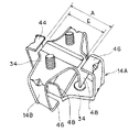
これら一対の支持腕部36,38の先端部は、質量体12の正面22側で互いに内向きに折曲されることで、左右一対の第1脱落規制壁部44,46に形成されている。すなわち、固定板部34から延設された支持腕部36,38は、質量体12の正面22を超えてから互いに内向きに垂直に折曲され、これにより形成された第1脱落規制壁部44,46が、質量体12の正面22の左右両側縁部22A,22Aとの間で前後方向Yに所定の間隔をおいて対向配置されている。従って、左右の第1脱落規制壁部44,46間の間隔(即ち、両第1脱落規制壁部44,46の先端同士の間隔)Aは、質量体12との間で重なり代を持つように、質量体12の左右方向Xにおける寸法Bよりも小さく設定されている(A<B、図4参照)。これにより、質量体12の正面22側への脱落、即ち質量体12が前方に脱落することが、上記一対の第1脱落規制壁部44,46により規制される。
The tip portions of the pair of
上記一対の第1脱落規制壁部44,46は、図4,5に示すように、前後方向Yから見て(即ち、図5に示す正面視において)、固定板部34に設けられた上記ボルト42の頭部42Aと重ならないように、当該頭部42Aと重なる位置の手前で終端するように設けられている。すなわち、第1脱落規制壁部44,46の先端(即ち、内端)は、図5に示すように、ボルト42の頭部42Aよりも左右方向Xにおける外方側に位置しており、頭部42Aにかからないように第1脱落規制壁部44,46は短く形成されている。
As shown in FIGS. 4 and 5, the pair of first drop-off restricting
図4,6に示すように、固定板部34の下縁34Cからは第2脱落規制壁部48が立設されている。第2脱落規制壁部48は、固定板部34の中央部に設けられた上記凸設部40の下端から前方に垂直に屈曲形成されており、質量体12の下面32との間で上下方向Zに所定の間隔をおいて対向するように設けられている。第2脱落規制壁部48は、質量体12の下面32の左右方向Xの中央部において前後方向Yに延びて設けられており、当該下面32の前後方向Yにおける途中で終端している。詳細には、図6に示すように、第2脱落規制壁部48の先端と第1脱落規制壁部44,46との間の前後方向Yにおける間隔Cが、質量体12の前後方向Yにおける寸法Dよりも小さく設定されている(C<D)。これにより、質量体12の下方への脱落が第2脱落規制壁部48により規制される。
As shown in FIGS. 4 and 6, a second drop-out restricting
そして、本実施形態では、左右の第1脱落規制壁部44,46間の間隔A(図4参照)が、固定板部34の高さE(図6参照)よりも大きく設定されている(A>E)。ここで、固定板部34の高さEとは、固定板部34の上下方向Zにおける最大寸法のことであり、この例では凸設部40が設けられた固定板部34の左右方向Xにおける中央部における上下方向寸法である。また、固定板部34の高さには、図6に示すように、第2脱落規制壁部48分の高さも含まれる。
And in this embodiment, the space | interval A (refer FIG. 4) between the left and right 1st drop-off
図4〜6に示すように、固定板部34と一対の支持腕部36,38との角部である屈曲部50,50と、支持腕部36,38と第1脱落規制壁部44,46との角部である屈曲部52,52には、それぞれ補強用のビード54が各1個、合計で4個設けられており、これにより支持金具14の変形を防止している。
4-6, the bending
上記弾性連結部16は、質量体12の左右両側面26,28とこれに対向する一対の支持腕部36,38の内側面との間にそれぞれ介設されており、これにより質量体12は、その左右両側部で一対の弾性連結部16,16を介して支持腕部36,38に弾性支持されるよう構成されている。
The elastic connecting
弾性連結部16は、図4〜6に示すように、上下方向Zの寸法よりも前後方向Yの寸法が大きい長方形状の断面形状をなして、水平に、即ち左右方向Xに延びて形成されており、両端部が質量体12と支持腕部36,38に加硫接着されている。弾性連結部16は、質量体12側の端部では、質量体12の側面26,28の中心部に結合されている。一方、支持腕部36,38側の端部では、図6に示すように上下方向Zの中心位置よりも下方にずらして結合されている。このように弾性連結部16を支持腕部36,38に対して下方にずらして結合させたことにより、質量体12の位置を下方にずらすことができ、これによって、車両搭載時に質量体12の上方に配される周辺部品との干渉を防止することができる。
As shown in FIGS. 4 to 6, the elastic connecting
弾性連結部16の支持腕部36,38との結合部は、支持腕部36,38の内側面との接着面積を大きく確保するように、上下方向Z及び前後方向Yにおいて幅広の台座部56に形成されている。弾性連結部16の支持腕部36,38側の結合部は、この台座部56の成形性を確保しつつ、できるだけ下方にずらされている。
The joint portion of the elastic connecting
質量体12の左右方向Xの両端部には、その周面を全周にわたって取り囲むストッパゴム部58が設けられている。ストッパゴム部58は、主として前後方向Yにおける過大変位に対して固定板部34や第1脱落規制壁部44,46に当接することでその変位を規制するとともに、衝突時の異音を防止するものであり、弾性連結部16から連なるゴム弾性体により一体に加硫成形されている。
ストッパゴム部58は、固定板部34に対向する部分58Aが、図4に示すように平面視で三角形状に形成されている。すなわち、この部分58Aは、左右方向Xで内方側ほど固定板部34から離間するような傾斜面状に形成されており、これにより、ストッパゴム部58の加硫成形時に、成形型がボルト42の頭部42Aとの間で干渉しないようにして、成形性を確保している。
In the
弾性連結部16とストッパゴム部58は、不図示の成形型内に質量体12と支持金具14をセットしてゴム材料を加硫成形することにより成形されるが、上記のような形状としたことで、成形型を、図6において線PLで示す箇所を割り位置とした上下割り構造とすることができ、製造しやすい。
The elastic connecting
以上説明した質量体12と支持金具14と弾性連結部16からなる本体部18は、図1〜3に示すように、取付部材20に固定されることでダイナミックダンパ10が構成される。取付部材20は、本体部18をその中央部に保持し、その下方と左右両側方に頂点を持つ略三角形状をなす板状部材であり、各頂点にはバックドア内部の被取付け面Fに不図示のボルトを用いて固定するためのボルト穴60が設けられている。
As shown in FIGS. 1 to 3, the
上記本体部18は、取付部材20に対し、固定板部34に溶接された2本のボルト42,42を介して固定されている。すなわち、取付部材20には該ボルト42が貫通する貫通穴62が対応する位置に設けられており、貫通穴62を貫通させたボルト42をナット64で締め付けて固定されている。
The
このように構成されたダイナミックダンパ10は、バックドア内部の被取付け面Fに対し、例えば、上記左右方向Xを車両左右方向とし、上記前後方向Yを車両前後方向として、取付部材20側を車両前方に向け、質量体12側を車両後方に向けて取り付けられる。
The
以上よりなる本実施形態のダイナミックダンパ10であると、上記のように支持金具14に左右一対の第1脱落規制壁部44,46と下側の第2脱落規制壁部48を設けたので、質量体12は、4つの側面22,24,26,28の全ての方向において、支持金具14の固定板部34、一対の支持腕部36,38及び第1脱落規制壁部44,46により、脱落が規制され、また下方への脱落は第2脱落規制壁部48によって規制される。よって、万が一、弾性連結部16が破断した場合でも、質量体12の脱落を防止することができる。
Since the
本実施形態であると、製造段階において、支持金具14を単品でランダムに重ねて置く場合に、仮に2つの支持金具14が絡み合おうとしたときでも、第2脱落規制壁部48を設けたことにより、図7に示すように、この第2脱落規制壁部48の存在によって2つの支持金具14A,14Bが深く絡み合うのを妨げることができる。すなわち、第2脱落規制壁部48が深く絡み合うのを防止するストッパとして機能するので、支持金具14A,14Bを分離しやすく、工程性に優れる。
In the present embodiment, in the manufacturing stage, when the
特に、本実施形態のものでは、左右一対の第1脱落規制壁部44,46間の間隔Aが、固定板部34の高さEよりも大きく設定されているので、図7に示すように絡み合った2つの支持金具14A,14Bにおいて、それぞれの上記間隔Aから固定板部34を容易に外すことができる。一方で、このように上記間隔Aが高さEよりも大きいと、この間隔Aから支持金具14Aの内部に他の支持金具14Bの固定板部34が入り込みやすくなるが、上記のように本実施形態のものでは第2脱落規制壁部48が深く絡み合うのを防止するので、絡み合いによる問題を最小限に食い止めることができる。逆に、例えば上記間隔Aが固定板部34の高さEよりも小さく設定されていると、間隔Aから支持金具14Aの内部に他の支持金具14Bの固定板部34は入り込みにくいが、一旦入り込んでしまうと、間隔Aが狭いことから外すのは容易でなくなり、工程性が損なうおそれがある。
In particular, in the present embodiment, since the distance A between the pair of left and right first drop-off restricting
本実施形態のものであると、また、第1脱落規制壁部44,46が、正面視でボルト42の頭部42Aと重ならないように当該頭部42Aと重なる位置の手前で終端した形状に設けられているので、弾性連結部16の加硫成形前の段階において、固定板部34にボルト42を溶接する際に、第1脱落規制壁部44,46が溶接の邪魔にならず、この点からも工程性に優れる。
In the present embodiment, the first drop-out restricting
なお、上記実施形態では、バックドア内部に組み込まれるダイナミックダンパについて説明したが、本発明はこれに限定されることなく、自動車などの車両を始めとして種々の振動体に対してその振動を低減するために用いることができる。また、上記の左右方向Xや前後方向Yは、あくまでダイナミックダンパ10単体での方向であり、車両搭載状態での左右方向や前後方向はこれに限定されるものではない。その他、本発明の趣旨を逸脱しない限り、種々の変更が可能である。
In the above embodiment, the dynamic damper incorporated in the back door has been described. However, the present invention is not limited to this, and the vibration is reduced with respect to various vibrating bodies including vehicles such as automobiles. Can be used for Further, the left-right direction X and the front-rear direction Y described above are directions of the
10…ダイナミックダンパ、12…質量体、14…支持金具、16…弾性連結部、22…質量体の正面、24,26…質量体の側面、32…質量体の下面、34…固定板部、34A…左右両側縁、34B…固定板部の固定面、34C…固定板部の下縁、36,36…支持腕部、42…ボルト、42A…頭部、42B…ねじ部、44,46…第1脱落規制壁部、48…第2脱落規制壁部、A…第1脱落規制壁部間の間隔、E…固定板部の高さ、X…左右方向、Y…前後方向、Z…上下方向
DESCRIPTION OF
Claims (3)
前記支持金具が、前記質量体の背面に対向して配されて前記取付部材に固定される固定板部と、前記固定板部の左右両側縁から立設されて前記質量体の左右両側面に各別に対向する左右一対の支持腕部とを備えてなり、
前記弾性連結部が、前記質量体の左右両側面と前記一対の支持腕部の内側面との間に介設され、これにより前記質量体が左右両側部で前記弾性連結部を介して前記支持腕部に弾性支持されたダイナミックダンパにおいて、
前記支持金具は、前記一対の支持腕部の先端部が前記質量体の正面側で互いに内向きに折曲した形状をなすことで前記質量体の正面側への脱落を規制する左右一対の第1脱落規制壁部が設けられるとともに、前記固定板部の下縁から立設されて前記質量体の下面に対向することで前記質量体の下方への脱落を規制する第2脱落規制壁部が設けられた、
ことを特徴とするダイナミックダンパ。 A rectangular parallelepiped mass body, a support fitting for supporting the mass body with respect to a mounting member for a vehicle, and an elastic connecting portion made of a rubber-like elastic body for connecting the mass body and the support fitting. A dynamic damper with
The support bracket is disposed opposite to the back surface of the mass body and fixed to the mounting member, and is erected from both right and left side edges of the fixed plate portion so as to be provided on the left and right side surfaces of the mass body. A pair of left and right support arms facing each other,
The elastic connecting portion is interposed between the left and right side surfaces of the mass body and the inner side surfaces of the pair of supporting arm portions, whereby the mass body is supported on the left and right side portions via the elastic connecting portion. In the dynamic damper elastically supported by the arm part,
The support metal fittings have a pair of left and right first members that regulate the falling off of the mass body to the front side by forming the distal ends of the pair of support arm portions inwardly bent at the front side of the mass body. A first drop-out restricting wall portion is provided, and a second drop-out restricting wall portion that is erected from the lower edge of the fixed plate portion and faces the lower surface of the mass body to restrict the dropout of the mass body downward. Provided,
This is a dynamic damper.
前記支持腕部の先端から内向きに延設された前記第1脱落規制壁部が、前後方向から見て前記ボルトの頭部と重ならないように当該頭部と重なる位置の手前で終端している、ことを特徴とする請求項1又は2記載のダイナミックダンパ。 The fixing plate portion has a bolt as a fixing means for the mounting member, a head portion is disposed on a surface facing the mass body, and a screw portion penetrates the fixing plate portion from the fixing surface side with respect to the mounting member. It is fixed so as to protrude,
The first drop-off restricting wall portion extending inwardly from the tip of the support arm portion is terminated before the position where it overlaps the head so that it does not overlap the head of the bolt when viewed from the front-rear direction. The dynamic damper according to claim 1, wherein the dynamic damper is provided.
Priority Applications (1)
| Application Number | Priority Date | Filing Date | Title |
|---|---|---|---|
| JP2009079829A JP5101552B2 (en) | 2009-03-27 | 2009-03-27 | Dynamic damper |
Applications Claiming Priority (1)
| Application Number | Priority Date | Filing Date | Title |
|---|---|---|---|
| JP2009079829A JP5101552B2 (en) | 2009-03-27 | 2009-03-27 | Dynamic damper |
Publications (2)
| Publication Number | Publication Date |
|---|---|
| JP2010230119A JP2010230119A (en) | 2010-10-14 |
| JP5101552B2 true JP5101552B2 (en) | 2012-12-19 |
Family
ID=43046136
Family Applications (1)
| Application Number | Title | Priority Date | Filing Date |
|---|---|---|---|
| JP2009079829A Active JP5101552B2 (en) | 2009-03-27 | 2009-03-27 | Dynamic damper |
Country Status (1)
| Country | Link |
|---|---|
| JP (1) | JP5101552B2 (en) |
Families Citing this family (1)
| Publication number | Priority date | Publication date | Assignee | Title |
|---|---|---|---|---|
| CN107165981B (en) * | 2017-05-23 | 2019-03-01 | 宁波拓普集团股份有限公司 | A kind of dynamic vibration absorber |
Family Cites Families (2)
| Publication number | Priority date | Publication date | Assignee | Title |
|---|---|---|---|---|
| JPH11210818A (en) * | 1998-01-28 | 1999-08-03 | Bridgestone Corp | Dynamic damper |
| JP2007100449A (en) * | 2005-10-06 | 2007-04-19 | Tokai Rubber Ind Ltd | Dynamic damper for home |
-
2009
- 2009-03-27 JP JP2009079829A patent/JP5101552B2/en active Active
Also Published As
| Publication number | Publication date |
|---|---|
| JP2010230119A (en) | 2010-10-14 |
Similar Documents
| Publication | Publication Date | Title |
|---|---|---|
| JP4755147B2 (en) | Vibration isolator | |
| JP6436786B2 (en) | Mounting device | |
| CN107218344B (en) | Dynamic vibration absorber | |
| JP2009185651A (en) | Oil pan | |
| JP2018127024A (en) | Power unit mounting structure | |
| JP5101552B2 (en) | Dynamic damper | |
| JP2008185201A (en) | Engine mount | |
| WO2009107810A1 (en) | Vibration-damping device | |
| JP5314467B2 (en) | Back door damper | |
| JP5364027B2 (en) | Dynamic damper | |
| JP5752458B2 (en) | Dynamic damper | |
| JP6823560B2 (en) | Dynamic damper | |
| JP4086854B2 (en) | Dynamic damper | |
| JP2011247333A (en) | Antivibration support structure | |
| JP2009041610A (en) | Dynamic damper | |
| JP4124370B2 (en) | Dynamic damper and dynamic damper mounting structure | |
| JP6780486B2 (en) | Vehicle front structure | |
| JP6601720B2 (en) | Bumper structure | |
| CN208101694U (en) | A kind of suspending apparatus and include the suspending apparatus vibration damping assembly | |
| JP6255962B2 (en) | Cowl part structure | |
| JP6000104B2 (en) | Mount member | |
| JP4256414B2 (en) | Steering wheel dynamic damper | |
| JP6693711B2 (en) | Soundproof structure for automobiles | |
| JP6515948B2 (en) | Powertrain mounting device | |
| JP5149773B2 (en) | Dynamic damper |
Legal Events
| Date | Code | Title | Description |
|---|---|---|---|
| A621 | Written request for application examination |
Free format text: JAPANESE INTERMEDIATE CODE: A621 Effective date: 20111130 |
|
| A977 | Report on retrieval |
Free format text: JAPANESE INTERMEDIATE CODE: A971007 Effective date: 20120907 |
|
| TRDD | Decision of grant or rejection written | ||
| A01 | Written decision to grant a patent or to grant a registration (utility model) |
Free format text: JAPANESE INTERMEDIATE CODE: A01 Effective date: 20120918 |
|
| A01 | Written decision to grant a patent or to grant a registration (utility model) |
Free format text: JAPANESE INTERMEDIATE CODE: A01 |
|
| A61 | First payment of annual fees (during grant procedure) |
Free format text: JAPANESE INTERMEDIATE CODE: A61 Effective date: 20120926 |
|
| FPAY | Renewal fee payment (event date is renewal date of database) |
Free format text: PAYMENT UNTIL: 20151005 Year of fee payment: 3 |
|
| R150 | Certificate of patent or registration of utility model |
Ref document number: 5101552 Country of ref document: JP Free format text: JAPANESE INTERMEDIATE CODE: R150 Free format text: JAPANESE INTERMEDIATE CODE: R150 |
|
| R250 | Receipt of annual fees |
Free format text: JAPANESE INTERMEDIATE CODE: R250 |
|
| S531 | Written request for registration of change of domicile |
Free format text: JAPANESE INTERMEDIATE CODE: R313531 |
|
| R350 | Written notification of registration of transfer |
Free format text: JAPANESE INTERMEDIATE CODE: R350 |
|
| R250 | Receipt of annual fees |
Free format text: JAPANESE INTERMEDIATE CODE: R250 |
|
| S533 | Written request for registration of change of name |
Free format text: JAPANESE INTERMEDIATE CODE: R313533 |
|
| R350 | Written notification of registration of transfer |
Free format text: JAPANESE INTERMEDIATE CODE: R350 |
|
| R250 | Receipt of annual fees |
Free format text: JAPANESE INTERMEDIATE CODE: R250 |
|
| R250 | Receipt of annual fees |
Free format text: JAPANESE INTERMEDIATE CODE: R250 |
|
| R250 | Receipt of annual fees |
Free format text: JAPANESE INTERMEDIATE CODE: R250 |
|
| R250 | Receipt of annual fees |
Free format text: JAPANESE INTERMEDIATE CODE: R250 |
|
| R250 | Receipt of annual fees |
Free format text: JAPANESE INTERMEDIATE CODE: R250 |