JP5098893B2 - Antenna installation support device, antenna installation support method, and program - Google Patents
Antenna installation support device, antenna installation support method, and program Download PDFInfo
- Publication number
- JP5098893B2 JP5098893B2 JP2008215409A JP2008215409A JP5098893B2 JP 5098893 B2 JP5098893 B2 JP 5098893B2 JP 2008215409 A JP2008215409 A JP 2008215409A JP 2008215409 A JP2008215409 A JP 2008215409A JP 5098893 B2 JP5098893 B2 JP 5098893B2
- Authority
- JP
- Japan
- Prior art keywords
- antenna
- antenna installation
- unit
- installation
- power
- Prior art date
- Legal status (The legal status is an assumption and is not a legal conclusion. Google has not performed a legal analysis and makes no representation as to the accuracy of the status listed.)
- Expired - Fee Related
Links
Images


Description
本発明は、無線通信機器と通信を行うアンテナの設置を支援する技術に関する。 The present invention relates to a technique for supporting installation of an antenna that communicates with a wireless communication device.
近年、携帯端末装置(携帯電話機やPDA(Personal Digital Assistants))やRFID(Radio Frequency IDentification)タグ等の、多数の無線通信機器と、アクセスポイントやリーダライタアンテナ等のアンテナを介して通信するシステムが提案されている(例えば、非特許文献1を参照)。非特許文献1のシステムでは、赤外線センサによる位置検出を併用したID検出や、ミドルウェア技術の開発によるデータ読み書きの最適化により、RFIDタグに対しデータの読み書きの確度を向上させることで、例えば1[m/s]で移動するRFIDタグ100枚を一括で読み取ることが可能である。
In recent years, a system that communicates with a large number of wireless communication devices such as mobile terminal devices (mobile phones and PDAs (Personal Digital Assistants)) and RFID (Radio Frequency IDentification) tags via an antenna such as an access point or a reader / writer antenna. (For example, refer nonpatent literature 1). In the system of Non-Patent
上記の非特許文献1のように多数のRFIDタグを一括で読み取るシステムでは、全てのRFIDタグに電波が到達するようにアンテナを設置する。特に、多数のRFIDタグは密集している場合が多く、アンテナの設置位置の影響を大きく受けるため、アンテナの設置位置を精度良く決定することが望まれる。
In a system that collectively reads a large number of RFID tags as in Non-Patent
一方、上記のような無線通信機器とアンテナを介して通信するシステムにおいて、アンテナと無線通信機器との間の電波の伝搬は、床や壁等の反射や屈折といった環境の影響を受ける。このため、アンテナの設置位置を決定する際に、環境の影響を考慮して精度を向上する。このように、環境の影響を考慮してアンテナの設置位置を決定する手法として、レイトレース法等によるシミュレーションを用いた手法が提案されている(例えば、特許文献1及び2を参照)。このレイトレース法では、アンテナから放射された電波が無線通信機器に到達する軌跡を追跡し、無線通信機器に到達した全ての電波の軌跡の電力を加算することで、各無線通信機器の位置での電界強度を算出して電界分布を算出する。そして、適切な電界分布が得られるようにアンテナの設置位置を決定する。
しかしながら、上記のようなレイトレース法等を用いたシミュレーションは、一般に、多大な計算時間を要する。しかも、アンテナを設置する際には、アンテナの位置を少しずつ変えてシミュレーションを繰り返して電界分布を算出し、最適な電界分布が得られるようにアンテナの設置位置を試行錯誤で決定するため、多大な労力や時間を要する。特に、多数の無線通信機器と通信するアンテナを設置する場合のように、設置位置の精度が要求される場合、シミュレーションを多数回繰り返すこととなり、効率が良くないという不都合があった。 However, the simulation using the ray tracing method as described above generally requires a lot of calculation time. Moreover, when installing an antenna, the position of the antenna is changed little by little, and the simulation is repeated to calculate the electric field distribution, and the antenna installation position is determined by trial and error so that an optimal electric field distribution is obtained. Takes a lot of effort and time. In particular, when the accuracy of the installation position is required as in the case of installing an antenna that communicates with a large number of wireless communication devices, the simulation is repeated many times, which is inefficient.
上記事情に鑑み、複数の無線通信機器と通信するアンテナの設置位置を簡易な処理で精度良く決定することが可能なアンテナ設置支援装置、アンテナ設置支援方法、及びプログラムを提供することを目的とする。 In view of the above circumstances, an object of the present invention is to provide an antenna installation support device, an antenna installation support method, and a program capable of accurately determining the installation positions of antennas that communicate with a plurality of wireless communication devices by simple processing. .
上記課題を解決するために、複数の無線通信機器と通信するアンテナの設置を支援するアンテナ設置支援装置であって、前記複数の無線通信機器の位置を機器位置としてそれぞれ設定する機器位置設定部と、前記アンテナの設置候補領域を設定するアンテナ設置候補領域設定部と、予め設定された放射パターンを用いて前記各機器位置から送信が行われた場合に、前記アンテナの設置候補領域が受ける電力の分布をそれぞれ算出する電力分布算出部と、前記電力分布算出部の算出結果に基づいて前記アンテナの設置位置を決定するアンテナ設置位置決定部と、を備えるアンテナ設置支援装置、該装置に適用されるアンテナ設置支援方法、及び該装置の処理をコンピュータに実行させる機能を備えたプログラムを提供する。 In order to solve the above-described problem, an antenna installation support device that supports installation of an antenna that communicates with a plurality of wireless communication devices, the device position setting unit configured to set the positions of the plurality of wireless communication devices as device positions, respectively The antenna installation candidate area setting unit for setting the antenna installation candidate area, and the power received by the antenna installation candidate area when transmission is performed from each device position using a preset radiation pattern. An antenna installation support device comprising: a power distribution calculation unit that calculates a distribution; and an antenna installation position determination unit that determines an installation position of the antenna based on a calculation result of the power distribution calculation unit, and is applied to the device An antenna installation support method and a program having a function of causing a computer to execute processing of the apparatus are provided.
上記のアンテナ設置支援装置、アンテナ設置支援方法、及びプログラムによれば、複数の無線通信機器と通信するアンテナの設置位置の決定を簡易な処理で精度良く行うことができる。 According to the antenna installation support device, the antenna installation support method, and the program described above, it is possible to accurately determine the installation position of an antenna that communicates with a plurality of wireless communication devices with simple processing.
上記のアンテナ設置支援装置の一実施形態であるアンテナ設置支援装置1について、図1〜図5を参照して説明する。アンテナ設置支援装置1は、複数のRFIDタグ(無線通信機器の一例)2と、RFIDタグ2と無線信号の送受信を行うアンテナ3とを備えた無線通信システム4において、アンテナ3の設置位置を決定する際に使用される。
The antenna
図1に、無線通信システム4の概要図を示す。本実施形態では、無線通信システム4として、折畳みコンテナの貸出管理ソリューションを示している。
FIG. 1 shows a schematic diagram of the
RFIDタグ2はパッシブ型であり、貸出管理のために必要な情報が埋め込まれ、アンテナ3からの電波をエネルギー源として動作し、アンテナ3からの電波の一部を反射波として情報を乗せて返す。このRFIDタグ2は、折畳みコンテナ5の所定箇所(折り畳まれた状態の側部)にそれぞれ取り付けられている(図1中、「○」を付して示している)。折畳みコンテナ5は、折り畳まれた状態で方形の板状であり、鉛直方向に積み重ねられて台車6に搭載されて運搬される。図1に示す例では、100個の折畳みコンテナ5が4つの山に分けて台車6に搭載されている。そして、台車6は、ラインLa,Lbで挟まれた間隔L[m]のゲート7の間を移動速度V[m/s]で移動する。このとき、ラインLa側の2つの山の折畳みコンテナ5は、RFIDタグ2がラインLa側を向くように積み重ねられ、ラインLb側の2つの山の折畳みコンテナ5は、RFIDタグ2がラインLb側を向くように積み重ねられている。
The
アンテナ3はリーダライタアンテナであり、RFIDタグ2に電波を供給して、通過したゲートの情報等をRFIDタグ2に書き込むと共に、RFIDタグ2からの反射波を受信して、貸出管理のために必要な情報を読み取る。アンテナ3は、ゲート7のラインLa,Lb上に設置されたアンテナポール8に取り付けられている。台車6がゲート7を通過する際に、ラインLa上のアンテナポール8に取り付けられたアンテナ3は、ラインLa側を向いたRFIDタグ2と通信し、ラインLb上のアンテナポール8に取り付けられたアンテナ3は、ラインLb側を向いたRFIDタグ2と通信する。このとき、アンテナ設置支援装置1は、複数のRFIDタグ2と一括で通信できるように、アンテナ3の設置位置(アンテナ3の設置数及び各アンテナ3の設置位置)を決定する。この決定された設置位置に応じて、ラインLa,Lb上でのアンテナポール8の位置及びアンテナポール8上でのアンテナ3の位置が決定される。
The
図2に、アンテナ設置支援装置1の機能ブロック図を示す。このアンテナ設置支援装置1は、図示しないCPU(Central Processing Unit)や、メモリ(ROM(Read Only Memory)11及び記憶部12)等により構成された電子ユニットを有し、その機能として、図2に示すように、制御部10と、記憶部12とを備えている。また、制御部10には、入力部13、表示部14が接続されている。入力部13は、例えばキーボードやタッチパネル等で構成され、ユーザによる操作の指示入力やデータの入力が行われる。また、表示部14は、例えばLCD(Liquid Crystal Display)等で構成され、操作指示やデータを入力するための入力画面や、入力データを図示する入力結果画面や、後述の出力データを図示する出力画面等が表示される。
In FIG. 2, the functional block diagram of the antenna
記憶部12は、入力データファイル15と、出力データファイル16とを保存している。入力データファイル15には、入力データとして、入力されたRFIDタグ2の位置やアンテナ3の設置候補領域、RFIDタグ2やアンテナ3の送信・受信の放射パターン、後述の電力分布算出処理で用いられる伝搬経路算出のためのパラメータ(反射回数・回折回数等)や伝搬環境モデル等が保存される。出力データファイル16には、出力データとして、後述の電力分布算出処理の結果として取得される伝搬経路や電力分布、決定されたアンテナの設定位置等が保存される。
The
制御部10は、各種の情報処理を実行するものであり、その機能として、入力制御部と、データ制御部と、表示制御部とを備えている(図示は省略)。入力制御部は、入力部13からの操作指示入力を受け付ける処理や、入力部13からのデータ入力を受け付けてデータを入力データファイル15へ記憶させる処理を実行する。データ制御部は、入力データや出力データの記憶部12への書き込みや読み出しを実行する。表示制御部は、表示部8に表示する表示画面を作成させる処理や、作成された画面を表示部8に表示させる処理を実行する。
The
さらに、制御部10は、その機能として、機器位置設定部24と、アンテナ設置候補領域設定部25と、電力分布算出部26と、機器位置群算出部27と、電力総和算出部28と、アンテナ設置位置決定部29とを備えている。なお、図2中、放射パターン設定部23は第2実施形態に備えるものであるので、ここでは説明を省略する。
Further, the
機器位置設定部24は、複数のRFIDタグ2の位置を機器位置(本実施形態ではタグ位置)としてそれぞれ設定する。具体的には、例えば、図1に例示したラインLa側については、タグ位置として、50個のRFIDタグ2の位置P1〜P50が設定される。
The device
アンテナ設置候補領域設定部25は、アンテナ3の設置候補領域を設定する。具体的には、例えば、図1に例示したラインLa側については、アンテナ3の設置候補領域として面Ra(図1中、破線で囲まれた領域)が設定される。
The antenna installation candidate
電力分布算出部26は、予め設定された放射パターンを用いて各タグ位置から送信が行われた場合に、アンテナ3の設置候補領域が受ける電力の分布をそれぞれ算出する。具体的には、電力分布算出部26は、入力データファイル15から放射パターンを読み出して用いる。この放射パターンは、RFIDタグ2とアンテナ3の一般的な特性から予め設定されている。
The power distribution calculation unit 26 calculates the distribution of power received by the installation candidate area of the
詳細には、電力分布算出部26は、プレ処理部30と、伝搬経路計算部31と、ポスト処理部32とを備えている。プレ処理部30は、計算条件の設定・保存や、入力データファイル15から読み出した放射パターンの離散化処理等を行う。伝搬経路計算部31は、プレ処理部30により処理された放射パターンを用いて、入力データファイル15に保存された反射回数・回折回数等に達するまで、送信点(タグ位置)からの放射電磁波の伝搬経路を計算する。ポスト処理部32は、伝搬経路計算部31による計算の結果から、指定された受信点までの伝搬経路の抽出や、指定された受信点における受信電力の算出を行う。受信点としては、アンテナ3の設置候補領域を部分領域に分割し、各部分領域をそれぞれ代表する候補点を用いる(例えば、中心点)。これにより、アンテナ設置候補領域が受ける電力の分布が算出される。
Specifically, the power distribution calculation unit 26 includes a
機器位置群算出部27は、電力分布算出部26の算出結果に基づいて、アンテナ3の設置候補領域の部分領域毎に、部分領域が受ける電力が所定閾値Wth以上となる機器位置(タグ位置)群を算出する。閾値Wthは、RFIDタグ2とアンテナ3とが無線信号の送受信を行う際に十分な電力の範囲として予め定められる。具体的には、機器位置群算出部27は、各部分領域をそれぞれ代表する候補点毎に、候補点がタグ位置から受ける電力を閾値Wthと比較して、比較結果を示す電力フラグを設定する。このとき、機器位置群算出部27は、電力が閾値Wth以上の場合、電力フラグに1を設定し、電力が閾値Wth未満の場合、電力フラグに0を設定する。タグ位置群は、電力フラグの値が1となるタグ位置の集合として示される。
Based on the calculation result of the power distribution calculation unit 26, the device position
電力総和算出部28は、アンテナ3の設置候補領域の部分領域毎に、部分領域が各タグ位置からそれぞれ受ける電力の総和を算出する。
The power
アンテナ設置位置決定部29は、電力分布算出部26の算出結果に基づいてアンテナ3の設置位置を決定する。詳細には、アンテナ設置位置決定部29は、機器位置群算出部27により算出されたタグ位置群に含まれるタグ位置の数に基づいて、アンテナ3の設置候補領域の部分領域を特定し、特定した部分領域をアンテナ設置位置として決定するものであり、部分領域を特定する第1の特定部33と第2の特定部34とを備える。
The antenna installation
第1の特定部33は、機器位置群算出部27による算出結果に基づいて、アンテナ3の設置候補領域の部分領域のうち、全てのタグ位置から受ける電力が閾値Wth以上となる部分領域を特定する。具体的には、第1の特定部33は、電力フラグが全て1となる候補点を特定する。そして、アンテナ設置位置決定部29は、第1の特定部33により特定された部分領域を第1のアンテナ設置位置として決定する。
Based on the calculation result by the device position
第2の特定部34は、第1の特定部33によりいずれの部分領域も特定されなかった場合に、アンテナ3の設置候補領域の部分領域のうち、機器位置群算出部27により算出されたタグ位置群に含まれるタグ位置の数が最も多い部分領域を特定する。具体的には、第2の特定部34は、電力フラグの値が1となるタグ位置が最も多い候補点を特定する。そして、アンテナ設置位置決定部29は、第2の特定部34により特定された部分領域を第2のアンテナ設置位置として決定する。
The
さらに、アンテナ設置位置決定部29は、第2のアンテナ設置位置について機器位置群算出部27により算出されたタグ位置群を第2のタグ位置群とする。そして、アンテナ設置位置決定部29は、第2のアンテナ設置位置を除いた部分領域について、機器位置群算出部27により算出されたタグ位置群に含まれる、第2のタグ位置群を除いたタグ位置の数に基づいて、アンテナ3の設置候補領域の部分領域を特定し、特定された部分領域をアンテナ設置位置として決定する。
Further, the antenna installation
また、アンテナ設置位置決定部29は、アンテナ設置位置を決定する際に、複数の部分領域が特定された場合に、特定された部分領域のうち、電力総和算出部28により算出された電力の総和が最も大きい部分領域をアンテナ設置位置として決定する。
Further, when determining the antenna installation position, the antenna installation
制御部10の機能は、アンテナ設置支援装置1に備えられたCPU(開示のアンテナ設置支援処理を実行させる機能を備えたプログラムで用いるコンピュータに相当する)により、メモリ(ROM11)に保存されたプログラムを実行させることにより実現される。このプログラムは、開示のアンテナ設置支援処理を実行させる機能を備えたプログラムを含む。
The function of the
次に、本実施形態のアンテナ設置支援装置1の作動(アンテナ設置支援処理)について、図3のフローチャートを参照して説明する。
Next, the operation (antenna installation support processing) of the antenna
ここで、比較として、従来のアンテナ設置支援処理について図10を参照して説明する。従来は、図10(a)に示すように、アンテナの位置を送信点として設定し、多数のRFIDタグが配置されている領域を受信面として設定する。そして、電力分布を算出するシミュレーションにより、アンテナからの放射電磁波の伝搬経路を計算して、アンテナから放射された電波が受信面に到達する軌跡を追跡し、受信面に到達した全ての伝搬軌跡の電力を加算することで、受信面が受ける電力を算出する。これにより、図10(b)に示すようにRFIDタグが配置されている領域が受ける電力の分布が算出される。この場合、全てのタグ位置での電力が、無線信号の送受信に十分な所定閾値以上となるまで、アンテナの位置を変更しながら電力分布を算出するシミュレーションを繰り返して、アンテナの設置位置を決定する。 Here, as a comparison, a conventional antenna installation support process will be described with reference to FIG. Conventionally, as shown in FIG. 10A, the position of the antenna is set as a transmission point, and an area where a large number of RFID tags are arranged is set as a reception surface. Then, by calculating the power distribution, the propagation path of the radiated electromagnetic wave from the antenna is calculated, the trajectory of the radio wave radiated from the antenna is traced to the reception surface, and all the propagation trajectories that have reached the reception surface are tracked. The power received by the receiving surface is calculated by adding the power. Thereby, as shown in FIG. 10B, the distribution of the power received by the area where the RFID tag is arranged is calculated. In this case, the antenna installation position is determined by repeating the simulation for calculating the power distribution while changing the antenna position until the power at all the tag positions becomes equal to or higher than a predetermined threshold sufficient for transmission and reception of radio signals. .
これに対して、本実施形態のアンテナ設置支援処理では、図3を参照して、まず、STEP1で、機器位置設定部24は、N個(N≧2)のRFIDタグ2の位置をタグ位置Pi(i=1〜N)として設定する。図4(a)に、設定されたタグ位置Piの例を模式的に示す。図4(a)は、ユーザから入力部13を介して入力されたタグ位置Piのデータを3次元座標系上で図示する入力結果画面を例示する。図4(a)において、設定されたタグ位置Pi が「+」を付して示されている。図4(a)の例では、縦4×横5で面上に分布した20個(N=20)のタグ位置P1〜P20が設定されている。このように、多数のRFIDタグ2について想定される配置からタグ位置Piが設定できる。このタグ位置P1〜P20は、後述のSTEP4の電力分布算出処理で送信点として用いられる。
In contrast, in the antenna installation support process of the present embodiment, referring to FIG. 3, first, in
次に、STEP2で、アンテナ設置候補領域設定部25は、アンテナ3の設置候補領域Rを設定する。図4(a)の例では、タグ位置P1〜P20に対向した平面Rが設定されている。この平面Rは、後述のSTEP4の電力分布算出処理で受信面として用いられる。
Next, in
次に、STEP3で、電力分布算出部26は、入力データファイル15から放射パターンを読み出す。
Next, in
次に、STEP4で、電力分布算出部26は、STEP1で設定されたタグ位置P1〜PNから送信が行われた場合に、アンテナ3の設置候補領域Rが受ける電力の分布をそれぞれ算出する。具体的には、電力分布算出部26は、各タグ位置Piを送信点とし、アンテナ3の設置候補領域RをM個の部分領域Rj(j=1〜M)に分割して、各部分領域Rjをそれぞれ代表する候補点Qj(j=1〜M)を受信点とする。そして、電力分布算出部26は、各タグ位置Piからの放射電磁波の伝搬経路を計算して、各タグ位置Piから放射された電波が各候補点Qjに到達する軌跡を追跡し、各候補点Qj に到達した全ての電波の軌跡の電力を加算することで、各候補点Qjが受ける電力を算出する。そして、電力分布算出部26は、候補点Q1〜QMが受ける電力から、アンテナ3の設置候補領域Rが受ける電力の分布を算出する。
Next, in
図4(b)に、算出された電力の分布を図示する出力画面を例示する。図4(b)には、アンテナ3の設置候補領域Rがタグ位置P1〜P20から受ける電力の総和の分布が示されている。図4(b)の例では、アンテナ3の設置候補領域Rが、縦10×横10で100個(M=100)の部分領域R1〜R100に分割され、部分領域R1〜R100 を代表する候補点Q1〜Q100が受ける電力が算出されている。この図では、部分領域R1〜R100に付された濃淡が、候補点Q1〜Q100が受ける電力の総和の大小を示している。
FIG. 4B illustrates an output screen illustrating the calculated power distribution. FIG. 4B shows the distribution of the total power received by the
このように、本実施形態では、実際は送信側であるアンテナ3を受信側としてシミュレーションを行い、アンテナ3の設置候補領域Rでの電力分布を算出する。これにより、この電力分布を用いて、後述のSTEP5〜17で、1回のシミュレーション結果からアンテナ3の設置位置を決定できると共に、設置候補領域Rにおけるアンテナ3の最適な設置位置を算出することができる。
Thus, in the present embodiment, the simulation is performed with the
次に、STEP5で、機器位置群算出部27は、STEP4の算出結果に基づいて、アンテナ3の設置候補領域Rの部分領域Rj毎に、タグ位置Piから受ける電力Wi j (i=1〜N,j=1〜M)が所定閾値Wth以上となるタグ位置群を算出する。具体的には、機器位置群算出部27は、候補点Qjがタグ位置Piから受ける電力Wijから、電力フラグFij(i=1〜N,j=1〜M)を設定する。このとき、機器位置群算出部27は、電力Wijが閾値Wth以上の場合、電力フラグFijに1を設定し、電力Wijが閾値Wth未満の場合、電力フラグFijに0を設定する。候補点Qjについてのタグ位置群は、N個のタグ位置P1〜PNのうち、電力フラグF1j〜FNjの値が1となるタグ位置の集合として示される。
Next, in STEP 5, the device position
ここで、図5(a)に、STEP4で算出された、タグ位置Piから受ける電力Wijの分布を図示する出力画面を例示する。図5(a)の例では、図4(b)の例と同様、アンテナ3の設置候補領域Rが、縦10×横10で100個(M=100)の部分領域R1〜R100に分割され、部分領域R1〜R100を代表する候補点Q1〜Q100が受ける電力が算出されている。この図では、部分領域R1〜R100に付された濃淡が、候補点Q1〜Q100がタグ位置Piから受ける電力Wijの大小を示している。STEP4では、20個のタグ位置P1〜P20について、それぞれ図5(a)のような電力の分布が得られる。
Here, FIG. 5A illustrates an output screen illustrating the distribution of the power W ij received from the tag position P i calculated in
このとき、図5(b)に示すように、電力Wij が、(タグ位置Piの個数)N×(候補点Qjの個数)Mの行列として得られる。そして、図5(c)に示すように、電力フラグFi j がN×Mの行列として得られる。このように、電力分布をN×Mの行列として表現し、さらに、電力フラグFi j の行列として表現することで、後述のSTEP6〜17で簡易な数値処理でアンテナ3の設置位置を決定することができる。
At this time, as shown in FIG. 5B, the electric power W ij is obtained as a matrix of (number of tag positions P i ) N × (number of candidate points Q j ) M. Then, as shown in FIG. 5C, the power flag F ij is obtained as an N × M matrix. In this way, the power distribution is expressed as an N × M matrix, and further expressed as a matrix of power flags F ij , so that the installation position of the
次に、STEP6で、第1の特定部33は、STEP5で算出した電力フラグFijの行列から、N個の電力フラグF1j〜FNjが全て1となる候補点Qjを特定する。これにより、全てのタグ位置P1〜PNから受ける電力W1j〜WNjが閾値Wth以上となる候補点Qjが特定される。上述の図5(c)に示す、STEP5で算出した電力フラグFi jの行列の一例について、説明上、電力フラグFijの行列が3×3の行列であるものとする。この場合、図5(c)の例では、3個の電力フラグ{F1j,F2j,F3j}が全て1となる候補点Qjとして、候補点Q3が特定される。
Next, in
次に、STEP7で、アンテナ設置位置決定部29は、STEP6でN個の電力フラグF1j〜FNjが全て1となる候補点Qj が特定されたか否かを判断する。STEP7の判断結果がYES(全て1の候補点Qj が特定された)の場合、STEP8に進み、アンテナ設置位置決定部29は、STEP7で特定された候補点Qjが1つであるか否かを判断する。STEP8の判断結果がYES(特定された候補点Qjが1つ)の場合、STEP9に進み、特定された候補点Qjを、アンテナ3の第1の設置位置として決定する。そして、アンテナ設置支援処理が終了される。
Next, in
図5(c)に示す例では、候補点Q3が1つ特定されているので、この候補点Q3 がアンテナ3の第1の設置位置として決定され、アンテナ設置支援処理が終了される。これにより、全てのRFIDタグ2と通信可能なアンテナ3の設置位置が決定される。
In the example shown in FIG. 5 (c), because the candidate point Q 3 are specified one, the candidate point Q 3 is determined as a first installation position of the
STEP8の判断結果がNO(特定された候補点Qjが複数ある)の場合、STEP10に進み、電力総和算出部28は、STEP6で特定された候補点Qjのそれぞれについて、タグ位置P1〜PNから受ける電力W1j〜WNjの総和Sj を算出する。この算出された電力の総和Sjが大きいほど、高い通信性能が得られる。
If the determination result in
次に、STEP11で、アンテナ設置位置決定部29は、STEP6で特定された候補点Qjのうち、電力の総和Sjが最も大きい候補点Qjを選択する。そして、STEP9に進み、アンテナ設置位置決定部29は、STEP11で選択した候補点Qjをアンテナ3第1の設置位置として決定する。そして、アンテナ設置支援処理が終了される。これにより、全てのRFIDタグ2と通信可能で、且つ最も高い通信性能が得られる設置位置が決定される。
Next, in
一方、STEP7の判断結果がNO(電力フラグが全て1の候補点Qjが特定されない)の場合、1つのアンテナ3で全てのRFIDタグ2と一括で通信することはできず、複数のアンテナ3を設置する必要がある。この場合、STEP12に進み、第2の特定部34は、STEP5で算出した電力フラグFijの行列から、N個の電力フラグ{F1j,F2j,…,FNj}について最も1が多い候補点Qjを特定する。図5(d)に、STEP5で算出した電力フラグFi jの行列の他の一例を示す。図5(d)に示す例について、説明上、電力フラグFi jの行列が3×3の行列であるものとする。この場合、図5(d)の例では、3個の電力フラグ{F1 j,F2 j,F3 j}が全て1となる候補点Qjが特定されないため、最も1が多い候補点Q3が特定される。
On the other hand, when the determination result of
次に、STEP13で、アンテナ設置位置決定部29は、STEP12で特定された候補点Qjが1つであるか否かを判断する。STEP13の判断結果がYES(特定された候補点Qjが1つ)の場合、STEP14に進み、アンテナ設置位置決定部29は、特定された候補点Qjを、アンテナ3の第2の設置位置として決定する。図5(d)に示す例では、1つの候補点Q3が特定されているので、この候補点Qjがアンテナ3の第2の設置位置として決定される。これにより、最も多いRFIDタグ2と通信可能なアンテナ3の設置位置が決定される。
Next, in
STEP13の判断結果がNO(特定された候補点Qjが複数ある)の場合、STEP15に進み、電力総和算出部28は、STEP10と同様に、STEP12で特定された候補点Qj のそれぞれについて、タグ位置P1〜PNから受ける電力W1j〜WNjの総和Sjを算出する。
When the determination result in
次に、STEP16で、アンテナ設置位置決定部29は、STEP12で特定された候補点Qjのうち、電力の総和Sjが最も大きい候補点Qjを選択する。そして、STEP14に進み、アンテナ設置位置決定部29は、STEP16で選択した候補点Qjをアンテナ3の第2の設置位置として決定する。これにより、通信可能なRFIDタグ2が最も多く、且つ最も通信性能が高いアンテナ3の設置位置が決定される。
Next, in
以下、STEP14で決定された第2の設置位置を候補点QXとして、候補点QX が受ける電力が所定閾値Wth以上となるタグ位置群を第2のタグ位置群とする。
Hereinafter, the second installation position as a candidate point Q X determined in
次に、STEP17で、アンテナ設置位置決定部29は、STEP14で設置位置として決定された候補点QXの電力フラグ{F1X,F2X,…,FNX}と、他の(M−1)個の候補点Qyの電力値フラグ{F1y,F2y,…,FNy}との論理和(OR)を算出する。そして、アンテナ設置位置決定部29は、算出後の値で電力値フラグFijの行列を更新する。これにより、更新した電力フラグF'i jが、N×(M−1)の行列として得られる。更新した電力フラグF'i jは、STEP14で決定された第2の設置位置を除いた候補点Qyについて、候補点Qyが受ける電力が所定閾値Wth以上となる、第2のタグ位置群を除いたタグ位置群を示す。図5(e)に、図5(d)に示した電力フラグFi jを更新した電力フラグF'i jを示す。
Next, in STEP 17, the antenna installation
次に、STEP6に戻り、アンテナ設置位置決定部29は、電力フラグFi jと同様に、更新した電力フラグF'i jの行列について、STEP6〜11の第1の特定処理、STEP12〜16の第2の特定処理を行い、アンテナ3の設置位置を決定していく。そして、STEP17で更新した電力フラグF'i jの行列について、第1の特定処理のSTEP9で、残りの全てのRFIDタグ2と通信可能なアンテナ3の設置位置が決定されるまで、これらの処理が繰り返される。
Next, returning to
上述の図5(e)に示した例では、次のSTEP6で、第1の特定部33が、更新した電力フラグF'i jの行列から、N個の電力フラグF1y〜FNyが全て1となる候補点Qyを特定する。これにより、3個の電力フラグ{F1y,F2y,F3y}が全て1となる候補点Qyとして、候補点Q2が特定される。この場合、候補点Q2が1つ特定されているので、この候補点Q2がアンテナ3の第1の設置位置として決定され、アンテナ設置支援処理が終了される。これにより、アンテナ3の設置位置として、2個の候補点Q3,Q2が決定される。このように、通信可能なRFIDタグ2が最も多い設置位置、最も高い通信性能が得られる設置位置を優先して、全てのRFIDタグ2と通信可能となるまで、設置位置が順次決定されていくので、最適な設置位置が効率良く決定される。
In the example shown in FIG. 5E described above, in the
以上が、アンテナ設置支援処理である。本実施形態によれば、1回のシミュレーション結果から、アンテナ3の設置位置を簡易な処理で容易に決定することができる。また、アンテナ3の設置候補領域Rにおける電力分布を用いてアンテナ3の設置位置が決定されるので、最適な設置位置が精度良く決定される。
[第2実施形態]
次に、第2実施形態のアンテナ設置支援装置1aについて図6〜図7を参照して説明する。第2実施形態は、第1実施形態と、電力分布算出処理で用いる放射パターンを算出して設定する放射パターン設定部23を備える点が相違する。以下の説明では、第1実施形態と同じ構成は同じ符号を付して説明を省略する。
The above is the antenna installation support processing. According to the present embodiment, the installation position of the
[Second Embodiment]
Next, the antenna installation support apparatus 1a of 2nd Embodiment is demonstrated with reference to FIGS. The second embodiment is different from the first embodiment in that it includes a radiation
放射パターン設定部23は、機器位置設定部24により設定されたタグ位置と、入力データファイル15に保存されている、RFIDタグ2間の干渉を考慮しない、独立した放射パターンとを用いて、RFIDタグ2の干渉を考慮した、各RFIDタグ2からの放射パターンを算出する。この算出された放射パターンは、データ制御部を介して入力データファイル15に保存される。電力分布算出部26は、この算出された放射パターンを用いて電力分布を算出する。他の構成は第1実施形態と同じである。
The radiation
本実施形態のアンテナ設置支援処理では、STEP3で、放射パターン設定部23は、入力データファイル15から予め定められた、RFIDタグ2の単独の放射パターンを読み出し、STEP1で設定されたタグ位置を用いて、RFIDタグ2間の干渉を考慮した放射パターンを算出する。
In the antenna installation support process of the present embodiment, in
図6に、本実施形態における、RFIDタグ2の配置を示す。図6では、30個のRFIDタグ2が、間隔2[mm]で鉛直方向(Z軸方向)に積み重ねられている(図6中、「○」を付して示している)。タグ位置として、30個のRFIDタグ2の位置P1〜P30が設定される。なお、図6中、RFIDタグ2から水平方向(XY平面と平行な方向)に伸びた直線部はアンテナエレメントである。
FIG. 6 shows an arrangement of the
このように、多数のRFIDタグ2が近接して配置されている場合、各RFIDタグ2の放射パターンは、電磁界の相互結合により、1個のRFIDタグ2が独立して配置されている場合とは相違したものとなる。そこで、電磁界シミュレーション等により、相互結合を考慮した放射パターンを算出する。
Thus, when a large number of
図7(a)に、1個のRFIDタグ2が独立して配置されている場合の放射パターンを示し、図7(b)に、30個のRFIDタグ2が図6に示すように配置されている場合の、タグ位置P15のRFIDタグ2の放射パターンを示す。なお、算出の条件として、タグ位置P15のRFIDタグ2のみに給電し、例えば、波源の内部インピーダンス、給電していないRFIDタグ2の終端インピーダンス等を設定する。図7(a)(b)において、3次元電磁界シミュレーションによる算出結果として、RFIDタグ2のタグ位置を原点として、3次元座標系でRFIDタグ2からの放射電磁波の伝搬経路に垂直な面が示されると共に、面を分割したメッシュ毎の電界強度の大小が色の濃淡で示されている。図7(a)(b)に示されるように、図6の多数のRFIDタグ2が近接して配置されている場合には、放射パターンの指向性が変化する。
FIG. 7 (a) shows a radiation pattern when one
本実施形態によれば、設定されたタグ位置を用いて、RFIDタグ2間の干渉を考慮して放射パターンを算出し、この算出した放射パターンを用いて電力分布を算出することで、実際の放射パターンが反映されて、電力分布の算出結果の精度が向上される。これにより、この電力分布の算出結果を用いたアンテナ3の設置位置の決定において精度を向上することができる。
[第3実施形態]
次に、第3実施形態のアンテナ設置支援装置について図8を参照して説明する。第3実施形態は、第1実施形態と、無線通信機器がアクティブRFIDタグであり、アンテナがリーダアンテナである点が相違する。以下の説明では、第1実施形態と同じ構成は同じ符号を付して説明を省略する。
According to the present embodiment, the radiation pattern is calculated using the set tag position in consideration of the interference between the RFID tags 2, and the power distribution is calculated using the calculated radiation pattern. Reflecting the radiation pattern, the accuracy of the calculation result of the power distribution is improved. Thereby, the accuracy can be improved in determining the installation position of the
[Third Embodiment]
Next, the antenna installation support apparatus of 3rd Embodiment is demonstrated with reference to FIG. The third embodiment is different from the first embodiment in that the wireless communication device is an active RFID tag and the antenna is a reader antenna. In the following description, the same components as those in the first embodiment are denoted by the same reference numerals and description thereof is omitted.
本実施形態のアンテナ設置支援装置1bは、複数のアクティブRFIDタグ(無線通信機器の一例)2bと、アクティブRFIDタグ2bと無線信号の送受信を行うリーダアンテナ3bとを備えた無線通信システム4bにおいて、リーダアンテナ3bの設置位置を決定する際に使用される。
An antenna installation support device 1b according to the present embodiment includes a plurality of active RFID tags (an example of a wireless communication device) 2b and a wireless communication system 4b including a
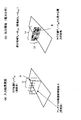
図8に、本実施形態のアンテナ設置支援装置1bが適用される無線通信システム4bの概要図を示す。本実施形態では、無線通信システム4bとして、荷物管理ソリューションを示している。 FIG. 8 shows a schematic diagram of a wireless communication system 4b to which the antenna installation support device 1b of the present embodiment is applied. In the present embodiment, a package management solution is shown as the wireless communication system 4b.
アクティブRFIDタグ2bは、荷物管理のために必要な情報が埋め込まれ、電池を内蔵して動作し、自ら電波を発してリーダアンテナ3bと情報の送受信を行う。また、アクティブRFIDタグ2bは、センサを内蔵し、センサによる検出値の変化をリーダアンテナ3bに通知することが可能である。このアクティブRFID2は、荷物5bの側面の所定箇所にそれぞれ取り付けられている(図8中、荷物5bの側面の黒塗り部分に相当する)。荷物5bは、複数の山に分けて鉛直方向に積み重ねられ、台車6bに搭載されて、所定の移動経路(図中、矢印で示す)で運搬される。
The active RFID tag 2b is embedded with information necessary for package management, operates with a built-in battery, and transmits and receives information with the
リーダアンテナ3bは、アクティブRFIDタグ2bからの電波を受信して、荷物管理のために必要な情報を読み取る。リーダアンテナ3bは、台車6bの移動経路上の天井に取り付けられている。
The
アンテナ設置支援装置1bは、複数のアクティブRFIDタグ2bと一括で通信できるように、リーダアンテナ3bの設置位置(リーダアンテナ3bの設置数及び各リーダアンテナ3bの設置位置)を決定する。この決定された設置位置に応じて、天井のリーダアンテナ3bの位置が決定される。
The antenna installation support device 1b determines the installation positions of the
機器位置設定部24は、複数のアクティブRFIDタグ2bの位置を機器位置としてそれぞれ設定する。具体的には、図8に示した例では、機器位置として8個のアクティブRFIDタグ2bの位置P1〜P8が設定される。
The device
アンテナ設置候補領域設定部25は、リーダアンテナ3bの設置候補領域として、台車6bの移動経路上の天井面Rbを設定する。他の構成及び作動は第1実施形態と同じである。
The antenna installation candidate
本実施形態によれば、複数のアクティブRFIDタグ2と無線信号の送受信を行うリーダアンテナ3bの設置位置を、簡易な処理で精度良く決定することができる。
According to the present embodiment, the installation position of the
なお、本実施形態において、第2実施形態と同様に、設定されたタグ位置を用いて、RFIDタグ2b間の干渉を考慮して放射パターンを算出し、この算出した放射パターンを用いて電力分布を算出し、リーダアンテナ3bの設置位置を決定するものとしてもよい。
[第4実施形態]
次に、第4実施形態のアンテナ設置支援装置1cについて図9を参照して説明する。第4実施形態は、第1実施形態と、無線通信機器が無線LAN(Local Area Network)内蔵PC(Personal Computer)であり、アンテナがアクセスポイントである点が相違する。以下の説明では、第1実施形態と同じ構成は同じ符号を付して説明を省略する。
In the present embodiment, as in the second embodiment, a radiation pattern is calculated using the set tag position in consideration of interference between the RFID tags 2b, and the power distribution is calculated using the calculated radiation pattern. And the installation position of the
[Fourth Embodiment]
Next, an antenna installation support apparatus 1c according to the fourth embodiment will be described with reference to FIG. The fourth embodiment differs from the first embodiment in that the wireless communication device is a wireless local area network (LAN) built-in PC (Personal Computer) and the antenna is an access point. In the following description, the same components as those in the first embodiment are denoted by the same reference numerals and description thereof is omitted.
図9に、本実施形態のアンテナ設置支援装置1cが適用される無線通信システム4cの概要図を示す。本実施形態では、無線通信システム4cとして、室内の各机5c上に配置された無線LAN内蔵PC 2cが、アクセスポイント3cを介して通信するシステムを示している。アクセスポイント3cは、室内の壁に取り付けられている。
FIG. 9 shows a schematic diagram of a wireless communication system 4c to which the antenna installation support device 1c of the present embodiment is applied. In the present embodiment, as the wireless communication system 4c, a system in which a wireless LAN built-in
アンテナ設置支援装置1cは、複数の無線LAN内蔵PC 2cと一括で通信できるように、アクセスポイント3cの設置位置(アクセスポイント3cの設置数及び各アクセスポイント3cの設置位置)を決定する。この決定された設置位置に応じて、壁のアクセスポイント3cの位置が決定される。
The antenna installation support device 1c determines the installation positions of the
機器位置設定部24は、複数の無線LAN内蔵PC 2cの位置を機器位置としてそれぞれ設定する。具体的には、図9に示した例では、機器位置として4個の無線LAN内蔵PC 2cの位置P1〜P4が設定される。
The device
アンテナ設置候補領域設定部25は、アクセスポイント3cの設置候補領域として、壁面Rcを設定する。他の構成及び作動は第1実施形態と同じである。
The antenna installation candidate
本実施形態によれば、複数の無線LAN内蔵PC2cと無線信号の送受信を行うアクセスポイント3cの設置位置を、簡易な処理で精度良く決定することができる。
According to the present embodiment, the installation position of the
なお、本実施形態において、第2実施形態と同様に、設定されたタグ位置を用いて、PC 2c間の干渉を考慮して放射パターンを算出し、この算出した放射パターンを用いて電力分布を算出して、アクセスポイント3cの設置位置を決定するものとしてもよい。
In the present embodiment, as in the second embodiment, a radiation pattern is calculated in consideration of interference between the
以上の実施形態に関し、更に以下の付記を開示する。 Regarding the above embodiment, the following additional notes are disclosed.
(付記1) 複数の無線通信機器と通信するアンテナの設置を支援するアンテナ設置支援装置であって、前記複数の無線通信機器の位置を機器位置としてそれぞれ設定する機器位置設定部と、前記アンテナの設置候補領域を設定するアンテナ設置候補領域設定部と、予め設定された放射パターンを用いて前記各機器位置から送信が行われた場合に、前記アンテナの設置候補領域が受ける電力の分布をそれぞれ算出する電力分布算出部と、前記電力分布算出部の算出結果に基づいて前記アンテナの設置位置を決定するアンテナ設置位置決定部と、を備えるアンテナ設置支援装置。 (Supplementary note 1) An antenna installation support device that supports installation of antennas that communicate with a plurality of wireless communication devices, each of which includes a device position setting unit that sets the positions of the plurality of wireless communication devices as device positions; The antenna installation candidate area setting unit for setting the installation candidate area and the distribution of power received by the antenna installation candidate area when transmission is performed from each device position using a preset radiation pattern. An antenna installation support device comprising: a power distribution calculation unit that performs an antenna installation position determination unit that determines an installation position of the antenna based on a calculation result of the power distribution calculation unit.
(付記2) 前記電力分布算出部の算出結果に基づいて、前記アンテナの設置候補領域の部分領域毎に、該部分領域が受ける電力が所定閾値以上となる機器位置群を算出する機器位置群算出部を備え、前記アンテナ設置位置決定部は、該機器位置群算出部により算出された機器位置群に含まれる機器位置の数に基づいて、前記アンテナの設置候補領域の部分領域を特定し、該特定した部分領域をアンテナ設置位置として決定する付記1記載のアンテナ設置支援装置。
(Additional remark 2) Based on the calculation result of the said electric power distribution calculation part, the apparatus position group calculation which calculates the apparatus position group for which the electric power which this partial area receives becomes more than a predetermined threshold for every partial area of the said antenna installation candidate area The antenna installation position determination unit identifies a partial region of the antenna installation candidate region based on the number of device positions included in the device position group calculated by the device position group calculation unit, The antenna installation support device according to
(付記3) 前記アンテナ設置位置決定部は、前記機器位置群算出部による算出の結果から、前記アンテナの設置候補領域の部分領域のうち、全ての機器位置から受ける電力がそれぞれ前記所定閾値以上となる部分領域を特定する第1の特定部を備え、該第1の特定部により特定された該部分領域を第1のアンテナ設置位置として決定する付記2記載のアンテナ設置支援装置。
(Additional remark 3) The said antenna installation position determination part is the electric power received from all the apparatus positions among the partial area | regions of the said antenna installation candidate area | region from the result of the calculation by the said apparatus position group calculation part, respectively more than the said predetermined threshold value The antenna installation support apparatus according to
(付記4) 前記アンテナ設置位置決定部は、前記第1の特定部によりいずれの部分領域も特定されなかった場合に、前記機器位置群算出部により算出された機器位置群に含まれる機器位置の数が最も多い部分領域を特定する第2の特定部を備え、該第2の特定部により特定された部分領域を第2のアンテナ設置位置として決定する付記3記載のアンテナ設置支援装置。
(Additional remark 4) The said antenna installation position determination part is an apparatus position included in the apparatus position group calculated by the said apparatus position group calculation part, when any partial area | region is not specified by the said 1st specific part. The antenna installation support apparatus according to
(付記5) 前記アンテナ設置位置決定部は、前記第2のアンテナ設置位置について前記機器位置群算出部により算出された機器位置群を第2の機器位置群として、該第2のアンテナ設置位置を除いた部分領域について、前記機器位置群算出部により算出された機器位置群に含まれる、該第2の機器位置群を除いた機器位置の数に基づいて、該アンテナの設置候補領域の部分領域を特定し、特定された該部分領域を該アンテナ設置位置として決定する付記4記載のアンテナ設置支援装置。
(Additional remark 5) The said antenna installation position determination part makes this 2nd antenna installation position the 2nd apparatus position group by using the apparatus position group calculated by the said apparatus position group calculation part about the said 2nd antenna installation position. For the excluded partial area, the partial area of the antenna installation candidate area based on the number of device positions, excluding the second device position group, included in the device position group calculated by the device position group calculating unit. The antenna installation support apparatus according to
(付記6) 前記アンテナの設置候補領域の部分領域毎に、該部分領域が各機器位置からそれぞれ受ける電力の総和を算出する電力総和算出部を備え、前記アンテナ設置位置決定部は、前記アンテナ設置位置を決定する際に、複数の部分領域が特定された場合に、特定された該部分領域のうち、該電力総和算出部により算出された電力の総和が最も大きい部分領域を決定する付記2〜5のうちいずれか記載のアンテナ設置支援装置。 (Supplementary Note 6) For each partial area of the antenna installation candidate area, the antenna installation position determination unit includes a power sum calculation unit that calculates a sum of power received from each device position by the partial area, and the antenna installation position determination unit includes the antenna installation When determining a position, when a plurality of partial areas are identified, among the identified partial areas, a partial area having the largest sum of power calculated by the power sum calculation unit is determined. The antenna installation support device according to any one of 5.
(付記7) 前記機器位置設定部により設定された機器位置に基づいて、該機器位置間の干渉を考慮して前記放射パターンを算出して設定する放射パターン設定部を備える付記1〜6のうちいずれか記載のアンテナ設置支援装置。 (Additional remark 7) Of the additional remarks 1-6 provided with the radiation pattern setting part which calculates and sets the said radiation pattern considering the interference between this apparatus position based on the apparatus position set by the said apparatus position setting part The antenna installation support device according to any one of the above.
(付記8) 複数の無線通信機器と通信するアンテナの設置を支援するアンテナ設置支援方法であって、複数の無線通信機器の位置を機器位置としてそれぞれ設定する機器位置設定ステップと、前記アンテナの設置候補領域を設定するアンテナ設置候補領域設定ステップと、予め設定された放射パターンを用いて前記各機器位置から送信が行われた場合に、前記アンテナの設置候補領域が受ける電力の分布を算出する電力分布算出ステップと、
前記電力分布算出ステップの算出結果に基づいて前記アンテナの設置位置を決定するアンテナ設置位置決定ステップと、を備えたアンテナ設置支援方法。
(Supplementary Note 8) An antenna installation support method for supporting installation of an antenna that communicates with a plurality of wireless communication devices, a device position setting step for setting each of the positions of the plurality of wireless communication devices as a device position, and installation of the antenna Antenna installation candidate area setting step for setting a candidate area, and power for calculating a distribution of power received by the antenna installation candidate area when transmission is performed from each device position using a preset radiation pattern Distribution calculation step;
An antenna installation support method comprising: an antenna installation position determination step that determines an installation position of the antenna based on a calculation result of the power distribution calculation step.
(付記9) 前記電力分布算出ステップの算出結果に基づいて、前記アンテナの設置候補領域の部分領域毎に、該部分領域が受ける電力が所定閾値以上となる機器位置群を算出する機器位置群算出ステップを備え、前記アンテナ設置位置決定ステップは、該機器位置群算出ステップにより算出された機器位置群に含まれる機器位置の数に基づいて、前記アンテナの設置候補領域の部分領域を特定し、該特定した部分領域をアンテナ設置位置として決定する付記8記載のアンテナ設置支援方法。
(Additional remark 9) Based on the calculation result of the said electric power distribution calculation step, the apparatus position group calculation which calculates the apparatus position group for which the electric power which this partial area receives becomes more than a predetermined threshold for every partial area of the said antenna installation candidate area The antenna installation position determination step specifies a partial region of the antenna installation candidate region based on the number of device positions included in the device position group calculated by the device position group calculation step; The antenna installation support method according to
(付記10) 前記アンテナ設置位置決定ステップは、前記機器位置群算出ステップによる算出の結果から、前記アンテナの設置候補領域の部分領域のうち、全ての機器位置から受ける電力がそれぞれ前記所定閾値以上となる部分領域を特定する第1の特定ステップを備え、該第1の特定ステップにより特定された該部分領域を第1のアンテナ設置位置として決定する付記9記載のアンテナ設置支援方法。 (Additional remark 10) The said antenna installation position determination step is the electric power received from all the apparatus positions among the partial area | regions of the said antenna installation candidate area | region from the calculation result by the said apparatus position group calculation step, respectively more than the said predetermined threshold value The antenna installation support method according to appendix 9, further comprising: a first specifying step of specifying a partial area to be determined, and determining the partial area specified by the first specifying step as a first antenna installation position.
(付記11) 前記アンテナ設置位置決定ステップは、前記第1の特定ステップによりいずれの部分領域も特定されなかった場合に、前記機器位置群算出ステップにより算出された機器位置群に含まれる機器位置の数が最も多い部分領域を特定する第2の特定ステップを備え、該第2の特定ステップにより特定された部分領域を第2のアンテナ設置位置として決定する付記10記載のアンテナ設置支援方法。
(Supplementary Note 11) In the antenna installation position determination step, when any partial area is not specified by the first specification step, the device position included in the device position group calculated by the device position group calculation step is determined. The antenna installation support method according to
(付記12) 前記アンテナ設置位置決定ステップは、前記第2のアンテナ設置位置について前記機器位置群算出ステップにより算出された機器位置群を第2の機器位置群として、該第2のアンテナ設置位置を除いた部分領域について、前記機器位置群算出ステップにより算出された機器位置群に含まれる、該第2の機器位置群を除いた機器位置の数に基づいて、該アンテナの設置候補領域の部分領域を特定し、特定された該部分領域を該アンテナ設置位置として決定する付記11記載のアンテナ設置支援方法。
(Supplementary Note 12) In the antenna installation position determination step, the device position group calculated by the device position group calculation step for the second antenna installation position is set as a second device position group, and the second antenna installation position is determined. For the excluded partial area, the partial area of the antenna installation candidate area based on the number of device positions excluding the second device position group included in the device position group calculated by the device position group calculating step. 12. The antenna installation support method according to
(付記13) 前記アンテナの設置候補領域の部分領域毎に、該部分領域が各機器位置からそれぞれ受ける電力の総和を算出する電力総和算出ステップを備え、前記アンテナ設置位置決定ステップは、前記アンテナ設置位置を決定する際に、複数の部分領域が特定された場合に、特定された該部分領域のうち、該電力総和算出ステップにより算出された電力の総和が最も大きい部分領域を決定する付記9〜12のうちいずれか記載のアンテナ設置支援方法。 (Supplementary Note 13) For each partial area of the antenna installation candidate area, the antenna installation position determining step includes a power sum calculation step of calculating a sum of power received by each partial area from each device position. Appendices 9 to 9 for determining a partial region having the largest sum of power calculated by the total power calculation step among the identified partial regions when a plurality of partial regions are specified when determining the position. The antenna installation support method according to any one of 12.
(付記14) 前記機器位置設定ステップにより設定された機器位置に基づいて、該機器位置間の干渉を考慮して前記放射パターンを算出して設定する放射パターン設定ステップを備える付記8〜13のうちいずれか記載のアンテナ設置支援方法。 (Additional remark 14) Of the additional remarks 8-13 provided with the radiation pattern setting step which calculates and sets the said radiation pattern considering the interference between this apparatus position based on the apparatus position set by the said apparatus position setting step Any antenna installation support method described.
(付記15)
複数の無線通信機器と通信するアンテナの設置を支援するアンテナ設置支援処理をコンピュータに実行させる機能を備えたプログラムであって、複数の無線通信機器の位置を機器位置としてそれぞれ設定する機器位置設定処理と、前記アンテナの設置候補領域を設定するアンテナ設置候補領域設定処理と、予め設定された放射パターンを用いて前記各機器位置から送信が行われた場合に、前記アンテナの設置候補領域が受ける電力の分布を算出する電力分布算出処理と、前記電力分布算出処理の算出結果に基づいて前記アンテナの設置位置を決定するアンテナ設置位置決定処理と、をコンピュータに実行させる機能を備えたプログラム。
(Appendix 15)
A device position setting process that has a function of causing a computer to execute antenna installation support processing for supporting installation of an antenna that communicates with a plurality of wireless communication devices, and sets the positions of the plurality of wireless communication devices as device positions. And antenna installation candidate area setting processing for setting the antenna installation candidate area, and the power received by the antenna installation candidate area when transmission is performed from each device position using a preset radiation pattern. A program having a function of causing a computer to execute a power distribution calculation process for calculating the distribution of the antenna and an antenna installation position determination process for determining an installation position of the antenna based on a calculation result of the power distribution calculation process.
(付記16) 前記電力分布算出処理の算出結果に基づいて、前記アンテナの設置候補領域の部分領域毎に、該部分領域が受ける電力が所定閾値以上となる機器位置群を算出する機器位置群算出処理を備え、前記アンテナ設置位置決定処理は、該機器位置群算出処理により算出された機器位置群に含まれる機器位置の数に基づいて、前記アンテナの設置候補領域の部分領域を特定し、該特定した部分領域をアンテナ設置位置として決定する付記5記載のプログラム。 (Additional remark 16) Based on the calculation result of the said electric power distribution calculation process, the apparatus position group calculation which calculates the apparatus position group from which the electric power which this partial area receives becomes more than a predetermined threshold for every partial area of the said antenna installation candidate area The antenna installation position determination process specifies a partial region of the antenna installation candidate area based on the number of device positions included in the device position group calculated by the device position group calculation process, The program according to appendix 5, wherein the specified partial area is determined as an antenna installation position.
(付記17) 前記アンテナ設置位置決定処理は、前記機器位置群算出処理による算出の結果から、前記アンテナの設置候補領域の部分領域のうち、全ての機器位置から受ける電力がそれぞれ前記所定閾値以上となる部分領域を特定する第1の特定処理を備え、該第1の特定処理により特定された該部分領域を第1のアンテナ設置位置として決定する付記6記載のプログラム。
(Supplementary Note 17) The antenna installation position determination process is based on a result of the calculation by the apparatus position group calculation process, and the power received from all the apparatus positions among the partial areas of the antenna installation candidate area is greater than or equal to the predetermined threshold value, respectively. The program according to
(付記18) 前記アンテナ設置位置決定処理は、前記第1の特定処理によりいずれの部分領域も特定されなかった場合に、前記機器位置群算出処理により算出された機器位置群に含まれる機器位置の数が最も多い部分領域を特定する第2の特定処理を備え、該第2の特定処理により特定された部分領域を第2のアンテナ設置位置として決定する付記17記載のプログラム。 (Supplementary Note 18) In the antenna installation position determination process, when any partial region is not specified by the first specifying process, the antenna installation position determining process includes the device position included in the apparatus position group calculated by the apparatus position group calculating process. 18. The program according to appendix 17, further comprising a second specifying process for specifying a partial area having the largest number, and determining the partial area specified by the second specifying process as a second antenna installation position.
(付記19) 前記アンテナ設置位置決定処理は、前記第2のアンテナ設置位置について前記機器位置群算出処理により算出された機器位置群を第2の機器位置群として、該第2のアンテナ設置位置を除いた部分領域について、前記機器位置群算出処理により算出された機器位置群に含まれる、該第2の機器位置群を除いた機器位置の数に基づいて、該アンテナの設置候補領域の部分領域を特定し、特定された該部分領域を該アンテナ設置位置として決定する付記18記載のプログラム。 (Supplementary Note 19) The antenna installation position determination process uses the device position group calculated by the device position group calculation process for the second antenna installation position as a second device position group, and determines the second antenna installation position. For the excluded partial area, the partial area of the antenna installation candidate area based on the number of device positions excluding the second device position group included in the device position group calculated by the device position group calculation process The program according to appendix 18, wherein the specified partial area is determined as the antenna installation position.
(付記20) 前記アンテナの設置候補領域の部分領域毎に、該部分領域が各機器位置からそれぞれ受ける電力の総和を算出する電力総和算出処理を備え、前記アンテナ設置位置決定処理は、前記アンテナ設置位置を決定する際に、複数の部分領域が特定された場合に、特定された該部分領域のうち、該電力総和算出処理により算出された電力の総和が最も大きい部分領域を決定する付記16〜19のうちいずれか記載のプログラム。
(Supplementary Note 20) For each partial area of the antenna installation candidate area, the antenna installation position determining process includes a power sum calculation process for calculating a sum of power received from each device position by the partial area.
(付記21) 前記機器位置設定処理により設定された機器位置に基づいて、該機器位置間の干渉を考慮して前記放射パターンを算出して設定する放射パターン設定処理を備える付記15〜20のうちいずれか記載のプログラム。 (Additional remark 21) Of additional remarks 15-20 provided with the radiation pattern setting process which calculates and sets the said radiation pattern considering the interference between this apparatus position based on the apparatus position set by the said apparatus position setting process One of the programs listed.
1,1a,1b,1c…アンテナ設置支援装置、2…パッシブRFIDタグ、3…リーダライタアンテナ、4…無線通信システム、10…制御部、11…ROM、12…記憶部、23…放射パターン設定部、24…機器位置設定部、25…アンテナ候補領域設定部、26…電力分布算出部、27…機器位置群算出部、28…電力総和算出部、29…アンテナ設置位置決定部、33…第1の特定部、34…第2の特定部、
2b…アクティブRFIDタグ、3b…リーダアンテナ
2c…無線LAN内蔵PC、3c…アクセスポイント。
DESCRIPTION OF
2b: Active RFID tag, 3b:
Claims (9)
前記複数の無線通信機器の位置を機器位置としてそれぞれ設定する機器位置設定部と、
前記アンテナの設置候補領域を設定するアンテナ設置候補領域設定部と、
予め設定された放射パターンを用いて前記各機器位置から送信が行われた場合に、前記アンテナの設置候補領域が受ける電力の分布をそれぞれ算出する電力分布算出部と、
前記電力分布算出部の算出結果に基づいて前記アンテナの設置位置を決定するアンテナ設置位置決定部と、
を備えるアンテナ設置支援装置。 An antenna installation support device that supports installation of an antenna that communicates with a plurality of wireless communication devices,
A device position setting unit for setting the position of each of the plurality of wireless communication devices as a device position;
An antenna installation candidate area setting unit for setting the antenna installation candidate area;
A power distribution calculation unit that calculates a distribution of power received by each antenna installation candidate area when transmission is performed from each device position using a preset radiation pattern; and
An antenna installation position determination unit that determines an installation position of the antenna based on a calculation result of the power distribution calculation unit;
An antenna installation support device comprising:
前記アンテナ設置位置決定部は、該機器位置群算出部により算出された機器位置群に含まれる機器位置の数に基づいて、前記アンテナの設置候補領域の部分領域を特定し、該特定した部分領域をアンテナ設置位置として決定する請求項1記載のアンテナ設置支援装置。 Based on the calculation result of the power distribution calculation unit, for each partial region of the antenna installation candidate region, a device position group calculation unit that calculates a device position group in which the power received by the partial region is a predetermined threshold or more,
The antenna installation position determination unit specifies a partial region of the antenna installation candidate region based on the number of device positions included in the device position group calculated by the device position group calculation unit, and the specified partial region The antenna installation support apparatus according to claim 1, wherein the antenna installation position is determined as an antenna installation position.
前記アンテナ設置位置決定部は、前記アンテナ設置位置を決定する際に、複数の部分領域が特定された場合に、特定された該部分領域のうち、該電力総和算出部により算出された電力の総和が最も大きい部分領域を決定する請求項2〜5のうちいずれか記載のアンテナ設置支援装置。 For each partial area of the antenna installation candidate area, a power total calculation unit that calculates the total power received by each partial area from each device position,
The antenna installation position determination unit, when determining a plurality of partial areas when determining the antenna installation position, out of the specified partial areas, the sum of the power calculated by the power total calculation unit The antenna installation support apparatus according to any one of claims 2 to 5, wherein a partial area having the largest value is determined.
複数の無線通信機器の位置を機器位置としてそれぞれ設定する機器位置設定ステップと、
前記アンテナの設置候補領域を設定するアンテナ設置候補領域設定ステップと、
予め設定された放射パターンを用いて前記各機器位置から送信が行われた場合に、前記アンテナの設置候補領域が受ける電力の分布を算出する電力分布算出ステップと、
前記電力分布算出ステップの算出結果に基づいて前記アンテナの設置位置を決定するアンテナ設置位置決定ステップと、
を備えたアンテナ設置支援方法。 An antenna installation support method for supporting installation of an antenna that communicates with a plurality of wireless communication devices,
A device position setting step for setting the positions of a plurality of wireless communication devices as device positions;
An antenna installation candidate area setting step for setting the antenna installation candidate area;
A power distribution calculating step of calculating a distribution of power received by the antenna installation candidate area when transmission is performed from each device position using a preset radiation pattern;
An antenna installation position determining step for determining an installation position of the antenna based on a calculation result of the power distribution calculating step;
Antenna installation support method with
複数の無線通信機器の位置を機器位置としてそれぞれ設定する機器位置設定処理と、
前記アンテナの設置候補領域を設定するアンテナ設置候補領域設定処理と、
予め設定された放射パターンを用いて前記各機器位置から送信が行われた場合に、前記アンテナの設置候補領域が受ける電力の分布を算出する電力分布算出処理と、
前記電力分布算出処理の算出結果に基づいて前記アンテナの設置位置を決定するアンテナ設置位置決定処理と、
をコンピュータに実行させる機能を備えたプログラム。
A program having a function of causing a computer to execute antenna installation support processing that supports installation of an antenna that communicates with a plurality of wireless communication devices,
Device position setting processing for setting the positions of a plurality of wireless communication devices as device positions respectively;
Antenna installation candidate area setting processing for setting the antenna installation candidate area;
A power distribution calculation process for calculating a distribution of power received by the antenna installation candidate area when transmission is performed from each device position using a preset radiation pattern;
An antenna installation position determination process for determining an installation position of the antenna based on a calculation result of the power distribution calculation process;
A program that has the function of running a computer.
Priority Applications (1)
| Application Number | Priority Date | Filing Date | Title |
|---|---|---|---|
| JP2008215409A JP5098893B2 (en) | 2008-08-25 | 2008-08-25 | Antenna installation support device, antenna installation support method, and program |
Applications Claiming Priority (1)
| Application Number | Priority Date | Filing Date | Title |
|---|---|---|---|
| JP2008215409A JP5098893B2 (en) | 2008-08-25 | 2008-08-25 | Antenna installation support device, antenna installation support method, and program |
Publications (2)
| Publication Number | Publication Date |
|---|---|
| JP2010050893A JP2010050893A (en) | 2010-03-04 |
| JP5098893B2 true JP5098893B2 (en) | 2012-12-12 |
Family
ID=42067585
Family Applications (1)
| Application Number | Title | Priority Date | Filing Date |
|---|---|---|---|
| JP2008215409A Expired - Fee Related JP5098893B2 (en) | 2008-08-25 | 2008-08-25 | Antenna installation support device, antenna installation support method, and program |
Country Status (1)
| Country | Link |
|---|---|
| JP (1) | JP5098893B2 (en) |
Families Citing this family (1)
| Publication number | Priority date | Publication date | Assignee | Title |
|---|---|---|---|---|
| JP5081136B2 (en) * | 2008-11-26 | 2012-11-21 | 日立Geニュークリア・エナジー株式会社 | Wireless communication device placement support system |
Family Cites Families (3)
| Publication number | Priority date | Publication date | Assignee | Title |
|---|---|---|---|---|
| JPH0787557A (en) * | 1993-09-13 | 1995-03-31 | Hitachi Ltd | Method and system for determining arrangement of indoor base station for mobile radio communication |
| JP2001285923A (en) * | 2000-03-31 | 2001-10-12 | Mitsubishi Electric Corp | Method for deciding base station arrangement pattern |
| JP4771068B2 (en) * | 2005-12-02 | 2011-09-14 | 日本電気株式会社 | Estimation method, estimation system, and program |
-
2008
- 2008-08-25 JP JP2008215409A patent/JP5098893B2/en not_active Expired - Fee Related
Also Published As
| Publication number | Publication date |
|---|---|
| JP2010050893A (en) | 2010-03-04 |
Similar Documents
| Publication | Publication Date | Title |
|---|---|---|
| EP2798571B1 (en) | Portable data tag reader device, system and method for identifying a location of a data tag | |
| JP4899464B2 (en) | Wireless tag communication device and communication method thereof | |
| EP2613574B1 (en) | System and method of providing a service using a near field communication tag | |
| CN101349746A (en) | Wireless radio frequency positioning method based on virtual reference label algorithm | |
| CN101363910A (en) | Wireless radio frequency positioning method based on Bayesian theory | |
| CN101320092A (en) | Positioning method based on wireless radio frequency recognition technology | |
| JP2006302219A (en) | Rfid tag communication range setting device | |
| CN203376473U (en) | Rfid indoor positioning system | |
| JP2011226959A (en) | Position detecting method for moving body | |
| JP4090808B2 (en) | Method and system for controlling proximity transactions | |
| US20130045682A1 (en) | System, mobile communication terminal and method for transferring information | |
| CN102647210A (en) | Communication apparatus, communication system, and communication method | |
| CN108364648A (en) | Method and device for obtaining audio-frequency information | |
| Tzeng et al. | Combination of radio frequency identification (RFID) and field verification tests of interior decorating materials | |
| Li et al. | Deployment strategies and performance evaluation of a virtual-tag-enabled indoor location sensing approach | |
| CN103278798A (en) | Three-dimensional calibration method for ship-borne personnel position | |
| US11843934B2 (en) | Methods and systems for tracking of assets and user navigation | |
| CN201780593U (en) | Fixed type wireless radiofrequency reader-writer | |
| JP5098893B2 (en) | Antenna installation support device, antenna installation support method, and program | |
| JP2007304874A (en) | System and device for specifying location of radio ic tag | |
| CN104076323A (en) | RFID positioning method based on simulation tag | |
| CN105449344A (en) | Antenna device for near-field communication, card reader and electronic device | |
| Yan et al. | A machine learning auxiliary approach for the distributed dense RFID readers arrangement algorithm | |
| KR20140024786A (en) | System for searching rfid tag and method therefor | |
| KR102359722B1 (en) | System for manage tangible assets using bluetooth sensor tag |
Legal Events
| Date | Code | Title | Description |
|---|---|---|---|
| A621 | Written request for application examination |
Free format text: JAPANESE INTERMEDIATE CODE: A621 Effective date: 20110513 |
|
| A977 | Report on retrieval |
Free format text: JAPANESE INTERMEDIATE CODE: A971007 Effective date: 20120824 |
|
| TRDD | Decision of grant or rejection written | ||
| A01 | Written decision to grant a patent or to grant a registration (utility model) |
Free format text: JAPANESE INTERMEDIATE CODE: A01 Effective date: 20120828 |
|
| A01 | Written decision to grant a patent or to grant a registration (utility model) |
Free format text: JAPANESE INTERMEDIATE CODE: A01 |
|
| A61 | First payment of annual fees (during grant procedure) |
Free format text: JAPANESE INTERMEDIATE CODE: A61 Effective date: 20120910 |
|
| FPAY | Renewal fee payment (event date is renewal date of database) |
Free format text: PAYMENT UNTIL: 20151005 Year of fee payment: 3 |
|
| R150 | Certificate of patent or registration of utility model |
Free format text: JAPANESE INTERMEDIATE CODE: R150 |
|
| LAPS | Cancellation because of no payment of annual fees |