JP5097612B2 - Air conditioner and air conditioning system - Google Patents
Air conditioner and air conditioning system Download PDFInfo
- Publication number
- JP5097612B2 JP5097612B2 JP2008122502A JP2008122502A JP5097612B2 JP 5097612 B2 JP5097612 B2 JP 5097612B2 JP 2008122502 A JP2008122502 A JP 2008122502A JP 2008122502 A JP2008122502 A JP 2008122502A JP 5097612 B2 JP5097612 B2 JP 5097612B2
- Authority
- JP
- Japan
- Prior art keywords
- indoor unit
- unit
- indoor
- light emission
- emission color
- Prior art date
- Legal status (The legal status is an assumption and is not a legal conclusion. Google has not performed a legal analysis and makes no representation as to the accuracy of the status listed.)
- Active
Links
- 238000004378 air conditioning Methods 0.000 title claims description 22
- 239000003507 refrigerant Substances 0.000 claims description 62
- 239000003086 colorant Substances 0.000 claims description 29
- 230000005856 abnormality Effects 0.000 claims description 28
- 238000001816 cooling Methods 0.000 description 12
- 238000010438 heat treatment Methods 0.000 description 10
- 239000011347 resin Substances 0.000 description 8
- 229920005989 resin Polymers 0.000 description 8
- XLYOFNOQVPJJNP-UHFFFAOYSA-N water Substances O XLYOFNOQVPJJNP-UHFFFAOYSA-N 0.000 description 8
- 238000009434 installation Methods 0.000 description 7
- 238000004891 communication Methods 0.000 description 4
- 239000002826 coolant Substances 0.000 description 4
- 238000010586 diagram Methods 0.000 description 4
- 238000001514 detection method Methods 0.000 description 2
- 238000012423 maintenance Methods 0.000 description 2
- 230000005540 biological transmission Effects 0.000 description 1
- 230000004397 blinking Effects 0.000 description 1
- 238000012790 confirmation Methods 0.000 description 1
- 239000004973 liquid crystal related substance Substances 0.000 description 1
- 238000004519 manufacturing process Methods 0.000 description 1
- 238000000034 method Methods 0.000 description 1
- 238000005086 pumping Methods 0.000 description 1
- 239000007787 solid Substances 0.000 description 1
- 238000010977 unit operation Methods 0.000 description 1
Images


Landscapes
- Air Conditioning Control Device (AREA)
Description
この発明は、リモコンにより運転を制御する空気調和機及び空気調和システムに関するものである。 The present invention relates to an air conditioner and an air conditioning system whose operation is controlled by a remote controller.
従来の空調システムは、複数の空気調和機と、空気調和機のそれぞれにより空調される室内の温度を設定するリモコンと、を備えている(例えば、特許文献1参照)。 The conventional air conditioning system includes a plurality of air conditioners and a remote controller that sets the temperature of the room that is air-conditioned by each of the air conditioners (see, for example, Patent Document 1).
特許文献1には具体的に記載されていないが、従来の空調システムの複数の空気調和機のそれぞれは、室外機と室内機とを有しているのが一般的である。そして、室内機が複数配設されているような室において、室内の一部のエリアのみが使用される場合には、すべての室内機を運転させる必要はなく、一部のエリアに対応する室内機のみを運転させればよい。しかし、例えば、室内機のそれぞれに対してリモコンが用意されているような場合、室内機のそれぞれ、及びリモコンのそれぞれは同一外観形状に製造されているので、室の使用者は、室内に置かれた複数のリモコンのうち、運転させたい室内機に対応するリモコンがどのリモコンなのかが一見しただけでは判断できない。
Although not specifically described in
そして、運転させたい室内機のみを運転させつつ従来の空調システムを運転させるためには、室の使用者は、運転させたい室内機が、任意のリモコンで運転開始操作を行ったときに運転したかどうかを確認するという煩わしい作業を、当該室内機が運転されるまで順次リモコンを代えて行う必要があった。この煩わしい確認作業を省略するため、室の使用者は、すべてのリモコンで運転開始操作を一斉に行い、室の一部のエリアを使用する場合でも、すべての室内機を運転させつつ室内の作業を行っていた。つまり、運転の必要のない室内機を運転させるため、空調システムの運転コストが不要に増大するという問題があった。 And in order to operate the conventional air conditioning system while operating only the indoor unit to be operated, the user of the room operated when the indoor unit to be operated performed the operation start operation with an arbitrary remote controller It is necessary to perform the troublesome work of checking whether or not the remote controller is sequentially changed until the indoor unit is operated. In order to omit this troublesome confirmation work, the room user performs the start operation with all remote controllers at the same time, and even when using a part of the room area, the room user operates all the indoor units and works indoors. Had gone. That is, since the indoor unit which does not need to be operated is operated, there is a problem that the operation cost of the air conditioning system increases unnecessarily.
この発明は、上記の課題を解決するためになされたものであり、室内機及びリモコンのそれぞれに、複数の色から指定した発光色を発光制御可能に配設した室内機側発光ユニット及びリモコン側発光ユニットのそれぞれを有する空気調和機及び空気調和システムを得ることを目的とする。 The present invention has been made in order to solve the above-described problems, and each of the indoor unit and the remote controller has an indoor unit side light emitting unit and a remote controller side, each of which has a light emission color designated from a plurality of colors so that the light emission can be controlled. It aims at obtaining the air conditioner and air conditioning system which have each of the light emission unit.
室内機、室内機と冷媒配管を介して接続された室外機、並びに室内機及び室外機の運転を制御するリモコンを備える空気調和機において、リモコンは、複数の色を発光可能に構成されたリモコン側発光ユニットと、複数の色から発光色を指定するリモコン側発光色設定手段と、運転条件の設定を行う設定部と、リモコン側発光ユニットの発光指令を行う発光指令手段と、運転条件に応じた運転制御信号を室内機に送信し、発光指令が行われたときに、リモコン側発光色設定手段で指定された発光色を発光させるようにリモコン側発光ユニットを発光制御するとともに、発光指令信号を室内機に送信するリモコン制御手段と、を備え、室内機は、複数の色を発光可能に構成された室外機側発光ユニットと、複数の色から発光色を指定するための室内機側発光色設定手段と、運転制御信号に基づいて室内機の運転を制御するとともに、発光指令信号の受信時に室内機側発光色設定手段で指定された発光色を発光させるように室内機側発光ユニットを発光制御する室内機制御手段と、を備えている。 In an indoor unit, an outdoor unit connected to the indoor unit via a refrigerant pipe, and an air conditioner including a remote control for controlling the operation of the indoor unit and the outdoor unit, the remote control is configured to emit a plurality of colors. Side light emitting unit, remote control side light emission color setting means for designating light emission color from a plurality of colors, setting unit for setting operating conditions, light emission command means for instructing light emission of the remote control side light emitting unit, and according to the operating conditions When the emission control command is transmitted to the indoor unit and a light emission command is issued, the light emission control is performed on the remote control side light emitting unit so that the light emission color specified by the remote control side emission color setting means is emitted, and the light emission command signal Remote controller control means for transmitting to the indoor unit, the indoor unit is an outdoor unit side light emitting unit configured to be capable of emitting a plurality of colors, and for specifying the emission color from the plurality of colors The indoor unit controls the operation of the indoor unit based on the indoor unit side emission color setting means and the operation control signal, and emits the emission color designated by the indoor unit side emission color setting unit when receiving the emission command signal. And an indoor unit control means for controlling light emission of the side light emitting unit.
この発明によれば、リモコンが、リモコン側発光色設定手段で指定された発光色を発光させるように、リモコン側発光ユニットを発光制御可能に構成され、室内機が、室内機側発光色設定手段で指定された発光色を発光させるように、室内機側発光ユニットを発光制御可能に構成されている。
従って、室内機側発光ユニット、及びリモコン側発光ユニットの発光色をそれぞれ指定することができるので、例えば、複数の室内機のグループと、当該グループのそれぞれに対してリモコンが用意された空気調和機を設置する場合、室内機と当該室内機を制御するリモコンにおける室内機側発光ユニット及びリモコン側発光ユニットの発光色をグループ内では同一とし、グループ間では異なる色となるように指定することができる。
According to this invention, the remote controller is configured to be able to control the light emission of the remote controller side light emitting unit so that the light emission color designated by the remote controller side light emission color setting means is emitted, and the indoor unit is configured to emit the indoor unit side light emission color. The indoor unit side light emitting unit is configured so as to be able to control light emission so as to emit the light emission color specified in.
Accordingly, the light emission colors of the indoor unit side light emitting unit and the remote controller side light emitting unit can be designated, respectively. For example, a group of a plurality of indoor units and an air conditioner in which a remote controller is prepared for each of the groups. When installing the indoor unit and the remote control that controls the indoor unit, it is possible to designate the emission color of the indoor unit side light emitting unit and the remote control side light emitting unit to be the same in the group and different colors between the groups. .
また、発光指令がリモコンで行われたときに、同時にリモコンから発光指令信号が室内機に送信されるように構成されている。これにより、すべてのリモコンで一斉に発光指令を行えば、リモコン及び室内機のすべてのリモコン発光ユニット及び室内機ユニットを指定した発光色で発光させることができる。
つまり、室の使用者は、運転させたい室内機の室内機側発光ユニットの発光色と同じ発光色のリモコン側発光ユニットを有するリモコンを見つけだすだけで、運転させたい室内機を制御するリモコンを選択できる。従って、運転させたい室内機のリモコンを選択するのに、順次任意のリモコンで運転開始操作を行って運転したかどうかを確認するという煩わしい作業を行う必要がなくなるので、運転の必要のない室内機を運転させたまま、室が使用されることが極力防止できる。すなわち、空調システムの運転コストが不要に増大することを抑制できる。
Further, when a light emission command is issued by the remote controller, a light emission command signal is simultaneously transmitted from the remote controller to the indoor unit. As a result, if a light emission command is issued simultaneously with all remote controllers, all remote control light emitting units and indoor unit units of the remote controller and indoor units can be made to emit light with a designated emission color.
In other words, the user of the room selects the remote control that controls the indoor unit to be operated simply by finding the remote controller having the remote control side light emitting unit that has the same emission color as the emission color of the indoor unit side light emitting unit of the indoor unit to be operated. it can. Therefore, it is not necessary to perform the troublesome operation of confirming whether or not the operation is started by sequentially performing the operation start operation with an arbitrary remote controller in order to select the remote controller of the indoor unit to be operated. It is possible to prevent the chamber from being used as much as possible while operating. That is, it is possible to suppress an unnecessary increase in the operating cost of the air conditioning system.
以下、この発明を実施するための最良の形態について、図面を参照して説明する。
実施の形態1.
図1はこの発明の実施の形態1に係る空気調和機が設置された建物の模式図、図2はこの発明の実施の形態1に係る空気調和機が設置された天井の平面図、図3は図2のA部拡大図、図4はこの発明の実施の形態1に係る空気調和機の室内機及び室外機の内部構成、及び冷媒の流れを説明する図、図5はこの発明の実施の形態1に係る空気調和機のシステム構成図、図6はこの発明の実施の形態1に係る空気調和機のリモコンの外観図である。
The best mode for carrying out the present invention will be described below with reference to the drawings.
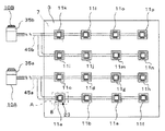
1 is a schematic diagram of a building in which an air conditioner according to
図1〜図3において、建物1の各階に、室2が天井3、床4、及び壁5に仕切られて設けられている。
そして、室2と天井裏7とを連通する設置口8が、図2に示されるように、4行4列で天井3に形成されている。そして、各階床の室2には、室2の空調を行う複数の空気調和機が配設さている。以下では、最上階の室2の空調を行う空気調和機10A,10Bで構成された空気調和システムについて説明する。
1 to 3, a
And the
空気調和機10Aは、天井3に複数配設され、同一冷媒系統で運転される室内機11a〜11hと、建物1の屋上に配設された室外機35aと、室2内の壁5に室内機11a〜11hと通信可能に配設され、室内機11a〜11h及び室外機35aの運転を制御する2台のワイヤードリモコン50a,50b(以下、リモコン50a,50bとする)と、室外機35aと室内機11a〜11hとの間を接続する冷媒配管45aと、を主たる構成として有している。
A plurality of air conditioners 10 </ b> A are arranged on the
また、空気調和機10Bは、空気調和機10Aと同様に構成され、天井3に複数配設され、同一冷媒系統で運転される室内機11i〜11pと、建物1の屋上に配設された室外機35bと、室2内の壁5に室内機11i〜11pと通信可能に配設され、室内機11i〜11p及び該室外機35bの運転を制御する2台のワイヤードリモコン50c,50d(以下、リモコン50c,50dとする)と、室外機35bと室内機11i〜11pのそれぞれとの間を接続する冷媒配管45bと、を主たる構成として有している。
なお、室内機11a〜11pのそれぞれ、及びリモコン50a〜50dのそれぞれは、同一外観形状に構成されている。
The air conditioner 10 </ b> B is configured in the same manner as the air conditioner 10 </ b> A, and a plurality of indoor units 11 i to 11 p that are disposed on the
In addition, each of
室内機11a〜11pのそれぞれは、設置口8のそれぞれに対応するように天井裏7に配設された本体部12、天井3に装着された化粧パネル23、及び化粧パネル23に装着された第1発光構成部29を備えている。
なお、図3では室内機11aを図示しているが、他の室内機11b〜11pも室内機11aと同様に構成されている。
Each of the
In addition, although the
そして、室内機11a〜11pは、図2に示されるように、天井3を前後左右で均等に4分割したときに、分割したそれぞれの天井3のエリアに、室内機11a〜11d、11e〜11h、11i〜11l、11m〜11pのそれぞれが配置されている。以下、室内機11a〜11d、11e〜11h、11i〜11l、11m〜11pを、それぞれ第1〜第4グループの室内機とする。
Then, as shown in FIG. 2, when the
以下、空気調和機10Aの室内機11a〜11hと室外機35aの詳細構成、及び各構成間の冷媒配管45aを介した接続関係について説明する。
Hereinafter, the detailed configuration of the
まず、室内機11aについて説明するが、室内機11b〜11hも室内機11aと同様の構成を有している。
図1〜図3において、室内機11aの本体部12は、詳細には図示しないが、設置口8のそれぞれから室2内を臨むように、天井裏7に配設されている。また、化粧パネル23は、室内吸込口24aと室内吹出口24bを有する矩形平板状の本体パネル24、及び裏面にフィルタ(図示せず)を有し、フィルタを室内吸込口24aに向けて当該室内吸込口24aと対面するように本体パネル24に装着された矩形平板状の吸込グリル25により構成されている。そして、化粧パネル23は、室2内の側から設置口8を塞口するように裏面を設置口8側に向けて天井3に装着されている。また、窓部28が、吸込グリル25の一角、及び当該部位と相対する本体パネル24の部位を切り欠いて形成されている。
First, although the
1 to 3, the
そして、第1発光構成部29は、図3に示されるように、窓部28に嵌めこまれた、透光性の樹脂からなる半透明の樹脂板30、及び複数の発光ダイオード33(LED33)からなる室内機側発光ユニットとしての第1LEDユニット32で構成されている。
第1LEDユニット32を構成するLED33のそれぞれは、赤、青、黄、紫、緑、橙のそれぞれを発光するものが用いられ、第1LEDユニット32は複数の色を発光可能になっている。そして第1LEDユニット32は、化粧パネル23の裏面側で、樹脂板30と相対するように配設されている。そして、LED33のいずれかが発光したときには、樹脂板30を介して発光したLED33の色が室2内から確認できるようになっている。
As shown in FIG. 3, the first
Each of the
図4及び図5において、室内機11aの本体部12は、室内熱交換器13、室内ファン14、膨張弁19、室内機制御手段15、及びロータリースイッチ21A,21Bなどを備えている。そして、ロータリースイッチ21A,21Bは、自身を備える室内機のアドレスを設定する室内機アドレス設定手段を構成するとともに、後述するように第1LEDユニット32の発光色を指定する室内機側発光色設定手段を構成している。
4 and 5, the
そして、室内機制御手段15は、図5に示されるように、CPU(図示せず)、データを保持するRAM(図示せず)、及び自身を備える室内機の運転制御用プログラムが格納されたROM(図示せず)などからなるマイコン16、並びに通信インタフェイス17(通信I/F17)を備えている。そして、室内機制御手段15は、室内ファン14の回転トルク制御や膨張弁19の加圧力制御を行う。
As shown in FIG. 5, the indoor unit control means 15 stores a CPU (not shown), a RAM (not shown) for holding data, and an indoor unit operation control program including itself. The
一対のロータリースイッチ21A,21Bのそれぞれは、電圧入力端子(図示せず)、軸まわりに回転する円盤状の回転部22、及び4本の出力端子(図示せず)を有している。そして、電圧が各ロータリースイッチ21A,21Bの入力端子に供給され、それぞれの出力端子は、回転部22の回転角度に応じて電気的にH(High)になったり、L(Low)になったりする。
Each of the pair of
そして、ロータリースイッチ21A,21Bは、回転部22の回転角度に応じて、4本の出力端子のそれぞれのHとLの組み合わせが10段階に変動するようになっている。また、ロータリースイッチ21A,21Bの出力端子の電圧は、室内機制御手段15に入力されてマイコン16で読み取り可能になっている。
The rotary switches 21 </ b> A and 21 </ b> B are configured such that the combination of H and L of the four output terminals varies in 10 steps according to the rotation angle of the rotating
そして、マイコン16では、一対のロータリースイッチ21A,21Bの10段階の出力状態のそれぞれを0〜9のそれぞれに対応させて、ロータリースイッチ21A,21Bのそれぞれの状態を認識している。つまり、マイコン16は、ロータリースイッチ21A,21Bのそれぞれの出力状態に対応する数値を10の位及び1の位として構成された00〜99の二桁の数値を、自身を備える室内機のアドレス(以下、自身の室内機アドレスとする)として認識している。ロータリースイッチ21A,21Bは、それぞれ回転させることができ、室内機のアドレスは、任意に切り替え可能である。
The
そして、各室内機11a〜11dのそれぞれに(01)〜(04)のアドレスのそれぞれが割り振られ、各室内機11e〜11hのそれぞれに(07)〜(10)のアドレスのそれぞれが割り振られている。
The addresses (01) to (04) are assigned to the
そして、各室内機11a〜11hのマイコン16のそれぞれは、認識した室内機アドレスに応じて複数色のLED33(第1LEDユニット32)の中から所定色のLED33の発光制御を行うようになっている。このとき、認識した室内機アドレスが(01)〜(06)である場合、マイコン16は青のLED33の発光制御を行い、認識した室内機アドレスが(07)〜(12)である場合、マイコン16は黄のLED33の発光制御を行うようになっている。つまり、ロータリースイッチ21A,21Bによる室内機アドレスの設定は、複数の色から第1LEDユニット32の発光色を指定していることに等しい。
このように、ロータリースイッチ21A,21Bは、複数の色のなかから発光させるLED33の発光色を指定するための室内機側発光色設定手段をも構成している。
And each of the
Thus, the rotary switches 21A and 21B also constitute indoor unit side emission color setting means for designating the emission color of the
つまり、(01)〜(04)のアドレスがそれぞれ割り振られた第1グループの室内機11a〜11dのマイコン16は、青のLED33の発光制御を行い、(07)〜(10)のアドレスがそれぞれ割り振られた第2グループの室内機11e〜11hのマイコン16は黄のLED33の発光制御を行うようになっている。
That is, the
次いで、室外機35aの構成について説明する。
図4、及び図5において、室外機35aは、室外熱交換器36、圧縮機37、室外ファン38、四方弁39、並びに圧縮機37の圧力調整、四方弁39の切り替え、及び室外ファン38の回転トルクなどを制御する室外機制御手段41などを備えている。
室外機制御手段41は、室内機制御手段15と同様にマイコン42及び通信I/F43で構成され、室内機11a〜11hと室外機35aとは通信可能に接続されている。
Next, the configuration of the
4 and 5, the
The outdoor unit control means 41 includes a
次いで、冷媒配管45aを介した本体部12及び室外機35aの各構成間の接続について図4を参照しつつ説明する。
冷媒配管45aは、室内機11a〜11hと室外機35aとの間で循環経路を構成するように配設されている。このとき、冷媒配管45aは、室内機11a〜11h側で分岐され、分岐された冷媒配管45aの部位は、並列に配置された室内機11a〜11hのそれぞれを経由したのち再度一つに統合されている。つまり、同一冷媒が室内機11a〜11hと室外機35aとの間を循環するように構成されている。
Next, connection between the components of the
The
室外機35aの四方弁39は4つの接続口を有し、そのうちの2つの接続口が圧縮機37の冷媒流入口と冷媒排出口に冷媒配管45aを介して接続され、残りの2つの接続口が室外熱交換器36または室内熱交換器13に冷媒配管45aを介して接続されている。
The four-
そして、冷媒配管45aは四方弁39、室外熱交換器36、膨張弁19、室内熱交換器13を通過する循環路を形成するように配設されている。このとき、室外機制御手段41が四方弁39を切り替えることで、冷媒の循環方向を、圧縮機37に出入りする冷媒の向きはそのままで、空気調和機10Aの冷房運転時と暖房運転時とで逆にすることが可能となっている。
And the refrigerant |
次いで、空気調和機10Aの冷房運転時と暖房運転時の冷媒の流れについて図4を参照しつつ説明する。なお、図4中、冷房運転時の冷媒の循環方向が実線の矢印で示され、暖房運転時の冷媒の循環方向が点線の矢印で示されている。
空気調和機10Aの冷房運転時には、四方弁39は実線で示されるように、圧縮機37の冷媒排出側を室外熱交換器36に接続し、圧縮機37の冷媒流入側を室内熱交換器13に接続している。そして、冷媒は低温低圧の気体の状態で圧縮機37に吸入されて圧縮され、高温高圧となって、室外熱交換器36へ送られ、室外熱交換器36で冷却されて液体化する。
Next, the refrigerant flow during the cooling operation and the heating operation of the
During the cooling operation of the
次に、液体化した冷媒は各室内機11a〜11hの膨張弁19に送られ、膨張弁19で気化しやすいように減圧されて、室内熱交換器13に送られる。液体化した冷媒は、室内熱交換器13を通過する冷媒配管45aの内部で室2の空気との熱交換によって室2内の空気の熱を奪うとともに気化され、四方弁39を介して再び圧縮機37へと戻るように循環する。また、室外ファン38及び室内ファン14のそれぞれが、空気調和機1の運転中、室外熱交換器36及び室内熱交換器13に気流を絶えず貫流させるように室内機制御手段15及び室外機制御手段41に制御されている。これにより、室外熱交換器36と室外の空気または室内熱交換器13と室2内の空気との熱交換が効率よく行われる。
Next, the liquefied refrigerant is sent to the
また、空気調和機10Aの暖房運転時には、四方弁39は点線で示されるように、圧縮機37の冷媒排出側を室内熱交換器13に接続し、圧縮機37の冷媒流入側を室外熱交換器36に接続するように切り替えられており、冷媒は冷房運転時とは逆方向に循環している。即ち、冷媒は低温低圧の気体の状態で圧縮機37に吸入されて圧縮され、高温高圧の状態で室内熱交換器13に送られる。そして、気体の冷媒は室内熱交換器13を通過する冷媒配管45aの内部で、室2の空気との熱交換によって室2内に熱を放出するとともに液化され、膨張弁19に送られる。そして、冷媒は気化しやすいように膨張弁19で減圧されて、室外熱交換器36に送られる。そして、冷媒は、室外熱交換器36を通過する冷媒配管45aの内部で、外気との熱交換によって、外気の熱を吸収するとともに気化し、四方弁39を介して再び圧縮機37に戻るように循環する。
Further, during the heating operation of the
次いで、リモコン50a,50bについて説明する。
図5及び図6において、リモコン50a,50bのそれぞれは、ケース51、複数のLED59で構成されるリモコン側発光ユニットとしての第2LEDユニット58を有する第2発光構成部57、及びロータリースイッチ21C,21Dを有している。
そして、ロータリースイッチ21C,21Dは、ロータリースイッチ21A,21Bと同様、自身を備えるリモコンのアドレスを設定するリモコン側アドレス設定手段を構成するとともに、第2LEDユニット58の発光色を指定するリモコン側発光色設定手段を構成している。
Next, the
5 and 6, each of the
The rotary switches 21C and 21D, like the
さらに、リモコン50a,50bのそれぞれは、空気調和機10Aの運転を開始させたり、停止させたり、空気調和機10Aの運転条件の設定を行う設定部61、第2LEDユニット58の発光指令を行う発光指令手段としての発光駆動スイッチ67、並びに現在の室内温度や目標設定温度、及び冷房運転又は暖房運転などの運転モードを表示するための表示部75を有している。さらに、リモコン50a,50bのそれぞれは、自身のアドレスや設定部61及び発光駆動スイッチ67での操作に基づいた制御を行うリモコン制御手段70を有している。
Further, each of the
設定部61及び発光駆動スイッチ67は、ケース51の一面に露出するように配設されている。
そして、設定部61は、図6に示されるように、空気調和機10Aの運転の開始と停止を切り替えるための運転/停止スイッチ62、空気調和機10Aの運転モードを切り替えるための運転切替スイッチ63、及び室2内の目標温度を設定するための温度設定ボタン64、風量切替スイッチ65を備えている。なお、運転モードとは、暖房運転、冷房運転、及び自動運転などである。
また、後述するように、運転/停止スイッチ62は、第2LEDユニット58の発光指令を行う発光指令手段としての機能も有している。さらに、発光駆動スイッチ67についても後述する。
The setting
Then, as shown in FIG. 6, the setting
Further, as will be described later, the operation /
また、窓部52がケース51の一面の角部近傍に開口するように形成されている。
Further, the
そして、第2発光構成部57は、第2LEDユニット58と、窓部52に嵌めこまれ、透光性の樹脂からなる半透明の第2樹脂板60と、で構成されている。
第2LEDユニット58を構成するLED59のそれぞれは、第1LEDユニット32を構成するLED33と同様に、赤、青、黄、紫、緑、橙のそれぞれの色を発光するものが用いられ、第2樹脂板60と相対するようにケース51内部に配設されている。そして、LED59が発光したときには、LED59の発光色に応じて第2樹脂板60の色が変化するようになっている。
And the 2nd light
Each of the
リモコン制御手段70は、CPU(図示せず)、データを保持するRAM(図示せず)、並びに通信I/F72及び自身を備えるリモコンの運転制御用プログラムが格納されたROM(図示せず)などからなるマイコン71などを備えている。そして、リモコン50a、50bは室内機11a〜11hと通信可能に接続されている。
また、ロータリースイッチ21C,21Dは、ロータリースイッチ21A,21Bと同様に構成されており、電圧が各ロータリースイッチ21C,21Dの図示しない入力端子に供給されている。
The remote control means 70 includes a CPU (not shown), a RAM (not shown) for holding data, and a ROM (not shown) in which a communication I /
The rotary switches 21C and 21D are configured in the same manner as the rotary switches 21A and 21B, and a voltage is supplied to input terminals (not shown) of the rotary switches 21C and 21D.
そして、ロータリースイッチ21C,21Dの出力端子の電圧は、リモコン制御手段70に入力され、マイコン71は、ロータリースイッチ21A,21Bの場合と同様に、00〜99の二桁の数値を、自身を備えるリモコンのアドレス(以下、自身のリモコンアドレスとする)として認識可能になっている。このとき、リモコン50a,50bのそれぞれのアドレスは、(51)及び(57)のそれぞれに設定されている。
Then, the voltages at the output terminals of the rotary switches 21C and 21D are input to the remote control means 70, and the
また、リモコン50a,50bのマイコン71のそれぞれは、認識したリモコンアドレスに応じて、複数の色のLED59(第2LEDユニット58)の中から所定の色のLED59の発光制御を行うように構成されている。そして、マイコン71は、認識したリモコンアドレスが(51)である場合、青のLED59の発光制御を行い、認識したリモコンアドレスが(57)である場合、黄のLED59の発光制御を行うようになっている。
Further, each of the
上述したように、リモコン50aが制御する第1グループの室内機11a〜11dが発光制御するLED33の発光色は青であり、リモコン50bが制御する第1グループの室内機11a〜11dが発光制御するLED33の発光色は黄である。
As described above, the emission color of the
従って、グループ内の室内機、及び当該室内機を制御するリモコンでは、ロータリースイッチ21A,21B、及びロータリースイッチ21C,21Dで指定された発光色は同一であり、グループ間では、室内機、及び室内機を制御するリモコンのそれぞれのロータリースイッチ21A,21B、及びロータリースイッチ21C,21Dで指定された発光色は異なっている。 Therefore, in the indoor unit in the group and the remote controller that controls the indoor unit, the emission colors specified by the rotary switches 21A and 21B and the rotary switches 21C and 21D are the same. The light emission colors designated by the rotary switches 21A and 21B and the rotary switches 21C and 21D of the remote controller for controlling the machine are different.
表示部75は液晶画面を有する表示パネルであり、表示部75の表示制御はマイコン71により行われ、設定部61で設定した目標設定温度や現在の室2内の温度、及び運転モードなどの情報が表示部75に表示されるようになっている。
The
そして、以下に説明するように、リモコン50a,50bのそれぞれは、同一のグループに属する室内機11a〜11d、及び室内機11e〜11hのそれぞれの運転制御を一括して行うように、グループのそれぞれに対して用意されている。
As will be described below, each of the
ここで、室内機11a〜11hのROMに格納されたプログラムには、自身を制御するリモコンのアドレスが第1受付許可アドレスとして書き込まれている。また、リモコン50a,50bのROMに格納されたプログラムには、自身が制御する室内機の室内機アドレスが第2受付許可アドレスとして書き込まれている。
Here, in the programs stored in the ROMs of the
そして、リモコン制御手段70は、運転/停止スイッチ62、運転切替スイッチ63、温度設定ボタン64、及び風量切替スイッチ65で行われた操作に応じて、運転開始信号(運転停止信号)、運転モード切り替え信号、目標設定温度信号、及び風量指定信号などの各種運転制御信号を室内機11a〜11hの室内機制御手段15に送信する。
Then, the remote control control means 70 performs an operation start signal (operation stop signal) and an operation mode switch according to operations performed by the operation /
このとき、リモコン制御手段70は、自身のリモコンアドレスの情報も室内機制御手段15のそれぞれに送信している。そして、各室内機11a〜11hの室内機制御手段15のマイコン16は、受信したアドレスが第1受付許可アドレスと一致しているときに、制御信号を受け付けるようになっている。
At this time, the remote control means 70 also transmits information on its own remote control address to each of the indoor unit control means 15. And the
つまり、第1グループの室内機11a〜11dの室内機制御手段15は、アドレス(51)のリモコン50aの運転制御信号を受け付け、第2グループの室内機11e〜11hの室内機制御手段15は、アドレス(57)のリモコン50bの運転制御信号を受け付けるよう設定されている。そして、室内機制御手段15のそれぞれは、運転制御信号に基づいて自身を備える室内機の運転を制御する。
That is, the indoor unit control means 15 of the first group
そして、運転制御信号を受け付けた第1グループの室内機11a〜11d及び第2グループの室内機11e〜11hのうち、最もアドレスの小さな室内機11a,11eの室内機制御手段15は、当該制御信号情報を、室外機35aの室外機制御手段41に送信する。
そして、運転制御信号を受け付けた室内機11a〜11d、11e〜11h、及び運転制御信号情報を受け付けた室外機35aの運転が開始され、空気調和機10Aによる室2内の空調運転が、制御信号に応じて行われる。このように、リモコン50a,50bのそれぞれが、第1グループの4台の室内機11a〜11d、及び第2グループの4台の室内機11e〜11hのそれぞれの運転制御を一括して行いつつ室外機35aの運転を制御することが可能になっている。
And among the
Then, the operation of the
次いで、発光駆動スイッチ67について説明する。
発光駆動スイッチ67は、ボタン式のものであり、ON/OFFの状態は、リモコン制御手段70のマイコン71で認識可能に配設されている。
Next, the light
The light
次いで、マイコン71及びマイコン16によるリモコン50a,50b及び室内機11a〜11hのLED33,59(第1LEDユニット32,第2LEDユニット58)の発光制御について説明する。
マイコン71及びマイコン16のそれぞれは、以下に説明するように、空気調和機10Aの運転時、発光駆動スイッチ67のスイッチがONに切り替わったとき、及び室内機11a〜11h側で異常が発生したときに、所定の発光色のLED33,59のそれぞれを発光または点滅させるように制御を行う。
Next, light emission control of the
As will be described below, each of the
まず、空気調和機10Aを運転させた場合のLED33,59の発光制御について説明する。空気調和機10Aの運転時におけるLED33,59の発光は、運転させた室内機が運転中であることを示す表示灯として、また、運転させた室内機に対応するリモコンの判別用として行う。
First, the light emission control of the
初期状態は、空気調和機10Aの運転が停止されているものとする。
そして、例えば、リモコン50aを操作して、空気調和機10Aの運転を開始する場合について説明する。リモコン50aのマイコン71は運転/停止スイッチ62により、運転開始操作が行われたときに、ロータリースイッチ21C,21Dで指定された発光色(青)に第2LEDユニット58を発光させるとともに、室内機11a〜11hに運転開始信号を送信する。このように、運転/停止スイッチ62は、第2LEDユニット58の発光指令を行う発光指令手段としての役割も有している。
In the initial state, it is assumed that the operation of the
Then, for example, a case where the operation of the
そして、リモコン50aにより運転を制御される室内機11a〜11dのマイコン16は、運転開始信号を受け付ける。運転開始信号を受け付けた室内機は、ロータリースイッチ21A,21Bで指定された色(青)のLED33を発光させる。つまり、運転開始信号は、当該信号を受け付けた室内機の第1LEDユニット32を発光させるように、室内機制御手段15に制御させるための発光指令信号としての機能も有している。
Then, the
そして、室2内からは、同じ発光色(青)のLED33,59が、運転開始操作を行ったリモコン50a、及び当該リモコン50aに制御される室内機11a〜11dで発光されていることが表示窓30,60を介して確認できる。
From the inside of the
また、リモコン50aのマイコン71は、運転切替スイッチ63により、運転停止操作が行われると、LED59の発光を停止するとともに、運転停止信号を室内機11a〜11hに送信する。そして、リモコン50aにより運転を制御される第1グループの室内機11a〜11dのマイコン16が、運転停止信号を受け付け、自身のLED33の発光を停止させる。
In addition, when the operation switching operation is performed by the
なお、リモコン50bで運転開始操作を行った場合には、同様に、リモコン50bのマイコン71及び室内機11e〜11hのマイコン16が、リモコン50b及び第2グループの室内機11e〜11hに配設された黄色のLED59,33の発光とその停止を制御する。
When the operation start operation is performed with the
次いで、発光駆動スイッチ67をONに切り替える操作が行われたときのLED33,59の発光について説明する。
例えば、リモコン50aのマイコン71は、発光駆動スイッチ67がONに切り替わるたびに、自身のリモコンアドレスに対応する色(青)のLED59を発光させる。さらに、当該マイコン71は、LED33を発光させるためのLED発光信号を、室内機11a〜11hに送信する。そして、リモコン50aにより運転を制御される室内機11a〜11dのマイコン16は、LED発光信号を受け付け、自身の室内機アドレスに対応する(ロータリースイッチ21A,21Bで指定された)色(青)のLED33を発光させる。そして、マイコン16及びマイコン71は、所定時間経過したらLED33,59の発光を停止するように設定されている。
Next, light emission of the
For example, each time the light
なお、リモコン50bの発光駆動スイッチ67が操作された場合には、同様に、リモコン50bのマイコン71及び室内機11e〜11hのマイコン16が、リモコン50bの黄色のLED59、及び第2グループの室内機11e〜11hの黄色のLED33の発光とその停止を制御する。
When the light
次いで、室内機11a〜11h側で異常が発生したときのLED33,59の発光について説明する。
各室内機制御手段15は、例えば、以下に説明するドレン排水異常などの各種異常が発生したときに異常を知らせる異常発生信号をリモコン50a,50bに送信する。
ドレン排水異常について説明する。周知であるので詳細には図示しないが、一般的に室内機11a〜11hにはドレン水を受ける周知のドレンパン、ドレンパン内の水位が異常に高くなったことを検知する水位異常検出センサ、及びドレン水を汲み上げて外部に排水するためのポンプなどが配設されている。そして、例えば、ドレン水がスライム化などして外部への排水経路を塞いだ場合などは、ドレンパンの水位が高くなる。このとき、水位異常検出センサがドレン排水異常を検知する。
Next, the light emission of the
Each indoor unit control means 15 transmits an abnormality occurrence signal notifying the abnormality to the
The drainage abnormality will be described. Although not shown in detail because it is well known, generally, the
ここでは、ドレン排水異常が室内機11aの水位異常センサで検出されたとする。このとき、室内機11aの室内機制御手段15のマイコン16は、自身が制御するLED29(青)を所定パターンで発光させるとともに、リモコン50a,50bに異常発生信号を送信する。また、マイコン16は、自身の室内機アドレスを同時に送信している。ここでは、所定パターンは点滅である。
そして、リモコン50a,50bのそれぞれのリモコン制御手段70のマイコン71は、第2受付許可アドレスの中に、受信した室内機11aのアドレス(01)が指定されているときに、異常発生信号を受け付けて以下の制御を行う。言い換えれば、マイコン71は、受信した室内機11aのアドレス(01)が、自身が制御する室内機のいずれかの室内機アドレスに一致しているときに、異常発生信号を受け付ける。
Here, it is assumed that the drain drainage abnormality is detected by the water level abnormality sensor of the
Then, the
そして、室内機11aを制御するリモコン50aのマイコン71が、異常発生信号を受け付け、マイコン71は、室内機11aからの異常発生信号に対し、表示部75に異常を発生した室内機のアドレス(01)、及び異常の種類を示すコードを表示するとともに、LED59(青)を所定パターン(点滅)で発光させるようになっている。
Then, the
以上、空気調和機10Aの室内機11a〜11h、室外機35a、及びリモコン50a,50bの具体的構成や、各構成間の冷媒配管45aを介した接続関係、並びにマイコン16,72による第1LEDユニット32のLED33及び第2LEDユニット58のLED59の発光制御について説明したが、空気調和機10Bの室内機11i〜11p、室外機35b、並びにリモコン50c,50dの具体的構成、各構成間の冷媒配管45bを介した接続関係、並びにマイコン16,72による第1LEDユニット32のLED33及び第2LEDユニット58のLED59の発光制御もまた空気調和機10Aと同様である。
As described above, the specific configurations of the
ただし、空気調和機10Bでは、(13)〜(16)のアドレスが第3グループの室内機11i〜11lに割り振られ、(19)〜(22)のアドレスが第4グループの室内機11m〜11pに割り振られている。
However, in the
そして、各室内機11i〜11pのマイコン16のそれぞれは、認識した室内機アドレスに応じて、複数色のLED33の中から所定色のLED33の発光制御を行うようになっている。このとき、マイコン16は、認識した室内機アドレスが(13)〜(18)である場合、紫のLED33の発光制御を行い、認識した室内機アドレスが(19)〜(24)である場合、緑のLED33の発光制御を行うようになっている。
つまり、(13)〜(16)のアドレスがそれぞれ割り振られた第3グループの室内機11i〜11lのマイコン16は、紫色のLED33の発光制御を行い、(19)〜(22)のアドレスがそれぞれ割り振られた第4グループの室内機11i〜11pのマイコン16は緑色のLED33の発光制御を行うようになっている。
And each of the
In other words, the
また、リモコン50c,50dのそれぞれのアドレスは、(63)及び(69)に設定されている。そして、リモコン50c,50dのマイコン71のそれぞれは、認識したリモコンアドレスに応じて、複数の色のLED59の中から所定の色のLED59の発光制御を行うように構成されている。そして、マイコン71は、認識したリモコンアドレスが(63)である場合、紫のLED59の発光制御を行い、認識したリモコンアドレスが(69)である場合、マイコン71は緑のLED59の発光制御を行うようになっている。即ち、リモコン50c,50dのそれぞれで制御されるLED59の発光色は、第3グループの室内機11i〜11l及び第4グループの室内機11m〜11pのマイコン16で制御されるLED33の発光色と同一である。
The addresses of the
さらに、第3グループの室内機11i〜11lの室内機制御手段15は、アドレス(63)のリモコン50aの制御信号を受け付け、第2グループの室内機11m〜11pの室内機制御手段15は、アドレス(69)のリモコン50bの制御信号を受け付けるよう設定されている。つまり、リモコン50c,50dのそれぞれが、第3グループの4台の室内機11i〜11l、及び第4グループの4台の室内機11m〜11pのそれぞれの運転制御を一括して行いつつ、室外機35bを運転させるようになっている。
Further, the indoor unit control means 15 of the third group of indoor units 11i to 11l receives the control signal of the
次に、室2の一部のエリアのみを使用する場合に、一部のエリアに対応する室内機(運転させたい室内機)のグループのみを運転させる手順の一例について説明する。
初期状態は、空気調和機10A,10Bの運転が停止されている。つまり、各室内機11a〜11pのマイコン16、及びリモコン50a〜50dのマイコン71は、LED33及びLED59のそれぞれの発光を停止している。
Next, an example of a procedure for operating only a group of indoor units (indoor units to be operated) corresponding to some areas when only a partial area of the
In the initial state, the operation of the
室2の使用者は、それぞれのリモコン50a〜50dの発光駆動スイッチ67を一斉に押す。前述したように、発光駆動スイッチ67が押されると、各リモコン50a〜50dのマイコン71は、自身のリモコンアドレスに対応する(ロータリースイッチ21C,21Dで指定された)色のLED59を発光させるとともに、LED発光信号を、室内機制御手段15に送信する。各室内機制御手段15のマイコン16は、室内機側LED発光信号を受信すると、それぞれ自身の室内機アドレスに対応する色のLED33を所定時間(例えば30秒)発光させるようになっている。
The user of the
つまり、リモコン50a〜50dの発光駆動スイッチ67が一斉に押されると、すべての室内機11a〜11p、及びリモコン50a〜50dで、それぞれのアドレスに対応する色のLED33,59が所定時間発光する。
That is, when the light emission drive switches 67 of the
このとき、室内機11a〜11p及び室内機11a〜11pを制御するリモコン50a〜50dのLED33,59は、同一色に発光するので、室2の使用者は、運転させたい室内機のLED33の発光色と同一色に発光しているLED59を有するリモコンを選択し、当該リモコンにより、空気調和機の運転操作を行えば、運転させたいグループの室内機のみを運転させて室2内の空調を行うことができる。
At this time, since the
例えば、第1グループの室内機11a〜11dの運転を制御するリモコン50aを選択する場合、当該室内機11a〜11dは、青のLED33を発光させているので、青のLED59を発光しているリモコン50aを選択すればよい。
For example, when the
なお、室内機11a〜11pのマイコン16及びリモコン50a〜50dのマイコン71は、所定色のLED33,59を発光させてから所定時間(例えば、30秒)経過しても、運転開始信号を受信しない場合には、LED33,59の発光を停止させる。また、各マイコン71は、所定時間経過内に自身が制御するリモコン50a〜50dのいずれかから運転開始信号を受信した場合には、所定時間経過後もLED33,59を発光させたままとする。
Note that the
この実施の形態1によれば、空気調和機10A,10Bの室内機11a〜11pのそれぞれが、ロータリースイッチ21A,21Bで指定された発光色を発光させるように、第1LEDユニット32を発光制御可能に構成され,リモコン50a〜50dのそれぞれが、ロータリースイッチ21C,21Dで指定された発光色を発光させるように、第2LEDユニット58を発光制御可能に構成されている。従って、第1LEDユニット32、及び第2LEDユニット58の発光色を、それぞれ空気調和機10A,10Bからなる空気調和システムの設置時に指定することができる。
According to the first embodiment, the
従って、第1LEDユニット32、及び第2LEDユニット58の発光色をそれぞれ指定することができるので、例えば、複数の室内機のグループと、当該グループのそれぞれに対してリモコンが用意された空気調和機を設置する場合、室内機と当該室内機を制御するリモコンにおける室内機側発光ユニット及びリモコン側発光ユニットの発光色をグループ内では同一とし、グループ間では異なる色となるように指定することができる。
Accordingly, since the emission colors of the
また、発光指令がリモコン50a,50b、50c,50dで行われたときに、同時にリモコン50a,50b、50c,50dから発光指令信号が室内機11a〜11h、11i〜11pに送信されるように構成されている。これにより、一斉にすべてのリモコン50a〜50dで発光指令操作を行えば、リモコン50a〜50d及び室内機11a〜11pのすべての第1LEDユニット32及び第2LEDユニット58を指定した発光色で発光させることができる。
Further, when a light emission command is issued by the
つまり、室2の使用者は、運転させたい室内機の第1LEDユニット32(LED33)の発光色と同じ発光色の第2LEDユニット58(LED59)を有するリモコンを見つけだすだけで、運転させたい室内機を制御するリモコンを選択できる。従って、運転させたい室内機のリモコンを選択するのに、順次任意のリモコンで運転開始操作を行って運転したかどうかを確認するという煩わしい作業を行う必要がなくなるので、運転の必要のない室内機を運転させたまま、室2が使用されることが極力防止できる。すなわち、空調システムの運転コストが不要に増大することを抑制できる。
That is, the user of the
また、リモコン50a〜50dのロータリースイッチ21C,21Dは、自身のリモコンアドレスを設定するリモコンアドレス設定手段を兼ねている。そして、リモコン制御手段70は、運転制御信号または上記発光指令信号の送信時に、設定された自身の上記リモコンアドレスを同時に送信し、室内機制御手段15は、受信したリモコンアドレスが自身の属するグループの室内機を制御するリモコンのリモコンアドレスに一致しているときに運転制御信号または発光指令信号を受け付けている。
この構成とすることにより、所定の室内機のグループのみを制御するようにリモコンのそれぞれを設定することが簡単に行える。
Further, the rotary switches 21C and 21D of the
With this configuration, it is possible to easily set each remote controller so as to control only a predetermined group of indoor units.
また、室内機制御手段15のロータリースイッチ21A,21Bは、自身の室内機アドレスを設定する室内機アドレス設定手段を兼ねている。そして、室内機制御手段15は、室内機11a〜11pのいずれかで異常を検知したときに、ロータリースイッチ21A,21Bで指定された発光色のLED33を所定パターンで発光させるように第1LEDユニット32を発光制御するとともに、リモコン50a,50または50c,50dに異常発生信号及び自身の上記室内機アドレスを送信する構成とされている。
The rotary switches 21A and 21B of the indoor unit control means 15 also serve as indoor unit address setting means for setting its own indoor unit address. And the indoor unit control means 15 is the
さらに、リモコン制御手段70は、受信したアドレスが、自身が制御するグループの室内機のいずれかの室内機アドレスに一致しているときに異常発生信号を受け付けて、ロータリースイッチ21C,21Dで指定された発光色のLED59を所定パターンで発光させるように第2LEDユニット58を発光制御する構成とされている。つまり、異常が空気調和機10Aまたは10Bの室内機11a〜11pのいずれかに発生した場合に、異常を発生した室内機及び当該室内機の運転を制御するリモコンのそれぞれのLED33,59が点滅する。従って、室2の使用者は、異常を発生した空気調和機10A,10Bの室内機がどの室内機なのかを速やかに判断できる。
Further, the
また、リモコン制御手段70は、発光指令が行われたときに指定された発光色のLED59を所定時間だけ発光させ、室内機制御手段15は、発光指令信号を受信したときに指定された発光色のLED33を所定時間だけ発光させる構成とされている。従って、運転させたい室内機を制御するリモコンを選択するときだけ、必要に応じてLED33、及びLED59を発光させることができる。
In addition, the remote control means 70 causes the
空気調和機10A,10Bで構成される空気調和システムは、ロータリースイッチ21A,21B及びロータリースイッチ21C,21Dで指定された発光色は、空気調和機10A,10Bのすべての室内機のグループ間で異なるように設定されている。これにより、空気調和システムにおいても、上述のように、室2の使用者は、運転させたい室内機の第1LEDユニット32(LED33)の発光色と同じ発光色の第2LEDユニット58(LED59)を有するリモコンを見つけだすだけで、運転させたい室内機を制御するリモコンを選択できる。
In the air conditioning system including the
なお、一つのリモコンで同一冷媒系統の4台の室内機の運転制御を一括して行うものとして説明したが、一つのリモコンで一括して運転制御する室内機の数は4台に限定されず、1台でもよいし、4台以外の複数の台数でもよい。つまり、複数の室内機のそれぞれが、複数のグループのいずれかに属するように割り振られ、リモコンが同一のグループに属する室内機の運転を制御するようにグループのそれぞれに対して用意されているものでもよい。 In addition, although it demonstrated that operation control of four indoor units of the same refrigerant system was collectively performed with one remote controller, the number of indoor units that are collectively controlled with one remote controller is not limited to four. One may be sufficient, and several numbers other than four may be sufficient. That is, each of the plurality of indoor units is allocated so as to belong to one of the plurality of groups, and the remote controller is prepared for each of the groups so as to control the operation of the indoor units belonging to the same group. But you can.
また、第1発光構成部29及び第2発光構成部57のそれぞれは、窓部28及び窓部52のそれぞれを有するものとして説明したが、窓部28及び窓部52は、第1LEDユニット32及び第2LEDユニット58のそれぞれの発光色が室2内から確認できれば、必ずしも配設する必要はない。
Moreover, although each of the 1st light
上述したように、室内機と室内機を制御するリモコンとは、ロータリ−スイッチ21A,21B及びロータリースイッチ21C,21Dで自由に設定可能なアドレスによって対応付けされている。これにより、例えば、室内機11e,11fのアドレスを07及び08に代え、05及び06のそれぞれに設定すれば、室内機11e及び室内機11fのマイコン16は、黄のLED33の発光制御に代え、青のLED33の発光制御を行う。このように、空気調和機10Aでは、リモコン50aで6台の室内機11a〜11fを制御し、リモコン50bで2台の室内機11g,11hを制御するように設定することもできる。また、空気調和機10Aを設置した後からでも、リモコン50a,50bが制御する室内機を変更することができるので、空気調和機10Aの設置時のみならず、設置後に仕様が変更された場合でも、変更した仕様に応じて、室内機11a〜11hと室内機11a〜11hを制御するリモコン50a,50bの対応付けを行うことができる。
As described above, the indoor unit and the remote controller that controls the indoor unit are associated with each other by addresses that can be freely set by the rotary switches 21A and 21B and the rotary switches 21C and 21D. Thereby, for example, if the addresses of the
また、予め、室内機11a〜11hと室内機11a〜11hを制御するリモコン50a,50bの対応付けが仕様により確実に決定されているような場合には、ロータリースイッチ21A,21B、及びロータリースイッチ21C,21Dは、必ずしも配設する必要はない。つまり、空気調和機10Aの製造時に、仕様に応じて室内機11a〜11hと室内機11a〜11hを制御するリモコン50a,50bを対応させ、予め、リモコン50a,50bとリモコン50a,50bにより制御される室内機11a〜11hをグループに分ける。そして、リモコン50aと室内機11aで発光させるLED33,59が、グループ内では同一色で、かつ、グループ間では異なる色となるようにして空気調和機10Aを製造する。そして、空気調和機10Aの設置時、リモコン50a,50bと、すべての室内機11a〜11hのすべての間を通信可能となるようにし、リモコン50a,50bのいずれかの発光駆動スイッチ67が操作されたときに、すべてのリモコン50a,50b、及びすべての室内機11a〜11hが制御対象とするLED33,59を発光させるように設定する。これにより、運転させたい室内機11a〜11hに対応するリモコン50a,50bを室2の使用者に選択させることができる。
In addition, when the correspondence between the
また、ロータリースイッチ21A,21Bが室内機側発光色設定手段、及び室内機アドレス設定手段を兼ねるものとして説明したが、室内機側発光色設定手段、及び室内機アドレス設定手段は別々に配設されているものでもよい。
また、ロータリースイッチ21C,21Dがリモコン側発光色設定手段、及びリモコンアドレス設定手段を兼ねるものとして説明したが、リモコン側発光色設定手段、及びリモコンアドレス設定手段は別々に配設されているものでもよい。
Further, the rotary switches 21A and 21B have been described as functioning as the indoor unit side emission color setting unit and the indoor unit address setting unit. However, the indoor unit side emission color setting unit and the indoor unit address setting unit are separately provided. It may be what you have.
Further, the rotary switches 21C and 21D have been described as functioning as the remote control side emission color setting means and the remote control address setting means. However, the remote control side emission color setting means and the remote control address setting means may be provided separately. Good.
また、1つの室外機に冷媒配管を介して8台の室内機を接続するものとして説明したが、1つの室外機に冷媒配管を介して8台の室内機を接続するものに限定されず、一つの室外機に冷媒配管を介して接続される室内機の台数は、1台でもよいし、8台の他の複数でもよい。 Moreover, although demonstrated as what connects eight indoor units to one outdoor unit via refrigerant piping, it is not limited to what connects eight indoor units to one outdoor unit via refrigerant piping, The number of indoor units connected to one outdoor unit through the refrigerant pipe may be one or may be other plural units of eight.
また、リモコン50a〜50dには、発光駆動スイッチ67を設けるものとして説明したが、発光駆動スイッチ67は必ずしも設けるものに限定されない。
この場合、運転させたいグループの室内機のみを運転させつつ空気調和機10Aまたは10Bを運転するには、一斉にリモコン50a〜50dの運転切替スイッチ63で運転を開始するように操作を行った後、運転させたいグループの室内機に対応するリモコンを除いたリモコンの運転切替スイッチ63で運転停止操作を行えばよい。
Further, the
In this case, in order to operate the
また、空気調和システムは、空気調和機10A,10Bで構成されるものとして説明したが、空気調和システムは、2組の空気調和機10A,10Bで構成されるものに限定されず、3組以上の複数の空気調和機で構成されているものでもよい。
この場合、室内機発光色設定手段で指定された発光色は、複数の空気調和機におけるすべてのグループ間で異なるように指定すればよい。
Moreover, although the air conditioning system was demonstrated as what is comprised with
In this case, the emission color specified by the indoor unit emission color setting means may be specified so as to be different among all groups in the plurality of air conditioners.
実施の形態2.
図7はこの発明の実施の形態2に係る空気調和機のリモコンの外観図である。
図7において、同一冷媒系統の室内機グループを識別させるための同一冷媒系統表記手段としてのテプラ76がリモコン50a〜50dのそれぞれに貼り付けられている。
なお、他の構成は上記実施の形態1と同様である。
FIG. 7 is an external view of a remote controller for an air conditioner according to
In FIG. 7, teplas 76 as the same refrigerant system notation means for identifying the indoor unit groups of the same refrigerant system are attached to each of the
Other configurations are the same as those in the first embodiment.
ここで、第1グループと第2グループの室内機11a〜11hは、同一冷媒系統であり、室内機11a〜11h側、及びリモコン側50a,50bで発光させるLED33,59の色は、青、または黄に制御されている。
Here, the
また、第3グループと第4グループの室内機11i〜11pは、同一冷媒系統であり、室内機11i〜11pを運転させるときに、室内機11i〜11p側、及びリモコン50c,50d側で発光させるLED33,59の色は、紫、または緑に制御されている。
そして、テプラ76には、図7に示されるように、同一冷媒系統:「青色と黄色」、「紫色と緑色」の表記がなされている。
The indoor units 11i to 11p of the third group and the fourth group are of the same refrigerant system, and when operating the indoor units 11i to 11p, the indoor units 11i to 11p and the
Further, as shown in FIG. 7, the
つまり、同一冷媒系統表記手段には、空気調和機10A,10Bのそれぞれに属する室内機11a〜11pのロータリースイッチ21A,21Bで指定されたすべての発光色が、同一冷媒系統で運転される室内機11a〜11h,11i〜11pの第1LEDユニット32の発光色群として表示されている。
これにより、青または黄を発光するLED33を有する各室内機のグループ、及び紫と緑を発光する室内機側を有する各室内機のグループがそれぞれ同一冷媒系統であることがすぐに確認できる。
That is, in the same refrigerant system notation means, all the luminescent colors designated by the rotary switches 21A and 21B of the
Thereby, it can be immediately confirmed that the group of each indoor unit having the
ここで、例えば、空気調和機10A,10Bのそれぞれにおいて、冷房運転時と暖房運転時とでは、冷媒の循環方向が逆となる。このため、それぞれ同一冷媒を循環させている空気調和機10Aの室内機11a〜11h、及び空気調和機10Bの室内機11i〜11pは、暖房と冷房を混在させて運転させるこができない。
Here, for example, in each of the air conditioners 10 </ b> A and 10 </ b> B, the refrigerant circulation direction is reversed between the cooling operation and the heating operation. For this reason, each of the
仮にテプラ76がリモコン50a〜50dに貼られていない場合、室2の使用者は同一冷媒系統の室内機のグループを認識できない。室2内の温度の感じ方には、人それぞれで個人差があるので、春や秋などは、例えば、室2の一の使用者が第1グループの室内機11a〜11dに冷房運転させるようにリモコン50aを操作し、さらに、室2の他の使用者が第2グループの室内機11e〜11hに暖房運転させるようリモコン50bを操作する場合がある。
If the
このとき、第1グループの室内機11a〜11dと室外機35aによる冷房運転が優先され、第2グループの室内機11e〜11hと室外機35aによる暖房運転動作は開始されない。
使用者は、空気調和機10Aが故障していないにも関わらず、空気調和機10Aの室内機11e〜11hの部分が運転を開始しないので、空気調和機10Aが故障したと勘違いしてしまう。これにより、空気調和機10Aの保守員を呼びよせるなど、本来は不要な対応をとってしまう場合もある。
At this time, the cooling operation by the first group
Although the
この実施の形態2では、同一冷媒系統の室内機グループのそれぞれで発光させるLED33の色をグループ化して表示しているので、同一冷媒系統の室内機のグループが周知徹底される。即ち、仮に空気調和機10A,10Bのそれぞれで、冷房と暖房を混在するように運転させる操作が、リモコン50a,50b又は50c,50dで行われてエラーが発生しても、室2の使用者は、当該エラーの原因を容易に気づくことができるので、不要に保守員を呼びよせてしまうことがなくなる。
In this
10A,10B 空気調和機、11a〜11p 室内機、15 室内機制御手段、21A,21B ロータリースイッチ(室内機側発光色設定手段、室内機アドレス設定手段)、21C,21D ロータリースイッチ(リモコン側発光色設定手段、リモコンアドレス設定手段)、32 第1LEDユニット(室内機側発光ユニット)、35a,35b 室外機、50a〜50d リモコン、58 第2LEDユニット(リモコン側発光ユニット)、61 設定部、67 発光駆動スイッチ(発光指令手段)、70 リモコン制御手段、76 テプラ(同一冷媒系統表示手段)。 10A, 10B air conditioner, 11a-11p indoor unit, 15 indoor unit control means, 21A, 21B rotary switch (indoor unit side emission color setting means, indoor unit address setting means), 21C, 21D rotary switch (remote control side emission color) Setting means, remote control address setting means), 32 first LED unit (indoor unit side light emitting unit), 35a, 35b outdoor unit, 50a-50d remote control, 58 second LED unit (remote control side light emitting unit), 61 setting unit, 67 light emission drive Switch (light emission command means), 70 remote control means, 76 tepla (same refrigerant system display means).
Claims (7)
上記リモコンは、複数の色を発光可能に構成されたリモコン側発光ユニットと、複数の色から発光色を指定するリモコン側発光色設定手段と、運転条件の設定を行う設定部と、上記リモコン側発光ユニットの発光指令を行う発光指令手段と、上記運転条件に応じた運転制御信号を上記室内機に送信し、上記発光指令が行われたときに、上記リモコン側発光色設定手段で指定された発光色を発光させるように上記リモコン側発光ユニットを発光制御するとともに、発光指令信号を上記室内機に送信するリモコン制御手段と、を備え、
上記室内機は、複数の色を発光可能に構成された室内機側発光ユニットと、複数の色から発光色を指定するための室内機側発光色設定手段と、上記運転制御信号に基づいて該室内機の運転を制御するとともに、上記発光指令信号の受信時に上記室内機側発光色設定手段で指定された発光色を発光させるように上記室内機側発光ユニットを発光制御する室内機制御手段と、を備え、
上記室内機が同一冷媒系統で運転されるように複数配設され、かつ、複数の該室内機のそれぞれは、複数のグループのいずれかに属するように割り振られ、上記リモコンが、同一の上記グループに属する上記室内機の運転を制御するように、上記グループのそれぞれに対して用意され、
上記グループ内では、上記室内機、及び該室内機を制御する上記リモコンにおける上記室内機側発光色設定手段、及び上記リモコン側発光色設定手段で指定された発光色が同一であり、かつ、上記グループ間では、上記室内機、及び該室内機を制御する上記リモコンにおける上記室内機側発光色設定手段、及び上記リモコン側発光色設定手段で指定された発光色が異なることを特徴とする空気調和機。 In an air conditioner including an indoor unit, an outdoor unit connected to the indoor unit via a refrigerant pipe, and a remote controller that controls the operation of the indoor unit and the outdoor unit,
The remote control includes: a remote control side light emitting unit configured to emit a plurality of colors; a remote control side emission color setting means for designating a light emission color from a plurality of colors; a setting unit for setting operating conditions; and the remote control side A light emission command means for issuing a light emission command for the light emitting unit and an operation control signal corresponding to the operation condition are transmitted to the indoor unit, and when the light emission command is issued, the light emission color setting means is designated by the remote controller side emission color setting means. Remote control control means for controlling the light emission of the remote control side light emitting unit so as to emit light emission color, and transmitting a light emission command signal to the indoor unit,
The indoor unit includes an indoor unit side light emitting unit configured to emit a plurality of colors, an indoor unit side light emission color setting means for designating a light emission color from a plurality of colors, and the operation control signal. Indoor unit control means for controlling the operation of the indoor unit and controlling the light emission of the indoor unit side light emitting unit so that the light emission color designated by the indoor unit side light emission color setting means is emitted when receiving the light emission command signal. , equipped with a,
A plurality of the indoor units are arranged so as to be operated by the same refrigerant system, and each of the plurality of indoor units is allocated to belong to one of a plurality of groups, and the remote controllers are assigned to the same group. Prepared for each of the groups so as to control the operation of the indoor units belonging to
Within the group, the indoor unit and the emission color designated by the indoor unit side emission color setting means and the remote control side emission color setting unit in the remote controller for controlling the indoor unit are the same, and between groups, the indoor unit, and the indoor-side light-emitting color setting means in the remote control for controlling the indoor machines, and emission color specified by the remote control light-emitting color setting means is characterized by different of Rukoto air Harmony machine.
上記リモコン制御手段は、上記運転制御信号または上記発光指令信号の送信時に、設定された自身の上記リモコンアドレスを同時に送信し、
上記室内機制御手段は、受信した上記リモコンアドレスが自身の属する上記グループの上記室内機を制御する上記リモコンの上記リモコンアドレスに一致しているときに上記運転制御信号または上記発光指令信号を受け付けることを特徴とする請求項1記載の空気調和機。 The remote control has remote control address setting means for setting its own remote control address,
The remote control means simultaneously transmits the set remote control address at the same time when transmitting the operation control signal or the light emission command signal,
The indoor unit control means receives the operation control signal or the light emission command signal when the received remote control address matches the remote control address of the remote controller that controls the indoor units of the group to which the indoor unit control means belongs. the air conditioner of claim 1 Symbol mounting characterized.
上記室内機制御手段は、上記室内機の異常を検知したときに、上記室内機側発光色設定手段で指定された発光色を所定パターンで発光させるように上記室内機側発光ユニットを発光制御するとともに、上記リモコンに異常発生信号及び自身の上記室内機アドレスを送信する構成とされ、
上記リモコン制御手段は、受信したアドレスが、自身が制御する上記グループの上記室内機のいずれかの室内機アドレスに一致しているときに上記異常発生信号を受け付けて、上記室内機側発光色設定手段で指定された発光色を所定パターンで発光させるように上記室内機側発光ユニットを発光制御する構成とされていることを特徴とする請求項2記載の空気調和機。 The indoor unit control means has an indoor unit address setting means for setting its own indoor unit address,
The indoor unit control means controls the light emission of the indoor unit side light emitting unit so that the emission color designated by the indoor unit side emission color setting means is emitted in a predetermined pattern when an abnormality of the indoor unit is detected. In addition, it is configured to transmit an abnormality occurrence signal and its own indoor unit address to the remote controller,
The remote control means accepts the abnormality occurrence signal when the received address matches one of the indoor unit addresses of the indoor units of the group controlled by the remote controller, and sets the emission color setting on the indoor unit side the air conditioner of claim 2 Symbol mounting, characterized in that the specified emission color is configured to emission control the indoor-side light-emitting unit to emit light in a predetermined pattern by means.
上記空気調和機のそれぞれは、上記室内機を一台のみ有し、上記リモコン側発光色設定手段、及び上記室内機側発光色設定手段で指定された発光色が上記室内機ごとに異なることを特徴とする空気調和システム。 In the air conditioning system provided with a plurality of air conditioners according to claim 1,
Each of the air conditioners has only one indoor unit, and the emission color specified by the remote controller side emission color setting means and the indoor unit side emission color setting means is different for each indoor unit. A characteristic air conditioning system.
上記室内機発光色設定手段で指定された上記発光色は、複数の上記空気調和機のすべての上記グループ間で異なっていることを特徴とする空気調和システム。 In the air conditioning system provided with a plurality of air conditioners according to claim 1 to claim 4 ,
The air conditioning system characterized in that the light emission color designated by the indoor unit light emission color setting means is different among all the groups of the plurality of air conditioners.
Priority Applications (1)
| Application Number | Priority Date | Filing Date | Title |
|---|---|---|---|
| JP2008122502A JP5097612B2 (en) | 2008-05-08 | 2008-05-08 | Air conditioner and air conditioning system |
Applications Claiming Priority (1)
| Application Number | Priority Date | Filing Date | Title |
|---|---|---|---|
| JP2008122502A JP5097612B2 (en) | 2008-05-08 | 2008-05-08 | Air conditioner and air conditioning system |
Publications (2)
| Publication Number | Publication Date |
|---|---|
| JP2009270779A JP2009270779A (en) | 2009-11-19 |
| JP5097612B2 true JP5097612B2 (en) | 2012-12-12 |
Family
ID=41437494
Family Applications (1)
| Application Number | Title | Priority Date | Filing Date |
|---|---|---|---|
| JP2008122502A Active JP5097612B2 (en) | 2008-05-08 | 2008-05-08 | Air conditioner and air conditioning system |
Country Status (1)
| Country | Link |
|---|---|
| JP (1) | JP5097612B2 (en) |
Families Citing this family (8)
| Publication number | Priority date | Publication date | Assignee | Title |
|---|---|---|---|---|
| JP5229301B2 (en) * | 2010-10-28 | 2013-07-03 | ダイキン工業株式会社 | Air conditioning system controller |
| JP5943678B2 (en) * | 2012-04-04 | 2016-07-05 | 三菱電機株式会社 | Remote controller for air conditioning |
| JP6091208B2 (en) * | 2012-12-27 | 2017-03-08 | 三菱電機株式会社 | Air conditioner controller and air conditioning system |
| CN104709166B (en) * | 2013-12-17 | 2017-07-11 | 韩昂系统有限公司 | Air conditioning system controller for motor vehicle |
| JP6360426B2 (en) * | 2014-11-06 | 2018-07-18 | アズビル株式会社 | Network control method and system |
| KR102000071B1 (en) * | 2017-10-12 | 2019-07-15 | 엘지전자 주식회사 | Air conditioner system and method for controlling the same |
| JP2019124998A (en) | 2018-01-12 | 2019-07-25 | アズビル株式会社 | Controller, operation state acquisition system and method |
| EP3919829B1 (en) * | 2019-01-31 | 2023-05-24 | Mitsubishi Electric Corporation | Multi-unit air conditioning system |
Family Cites Families (4)
| Publication number | Priority date | Publication date | Assignee | Title |
|---|---|---|---|---|
| JPH06257837A (en) * | 1993-03-08 | 1994-09-16 | Matsushita Seiko Co Ltd | Remote controlling control device |
| JP2006109515A (en) * | 2000-08-17 | 2006-04-20 | Daikin Ind Ltd | Remote control type device |
| JP3994671B2 (en) * | 2001-02-20 | 2007-10-24 | 松下電器産業株式会社 | Remote control transmitter for air conditioner |
| JP2007303820A (en) * | 2007-08-28 | 2007-11-22 | Toshiba Kyaria Kk | Air conditioner |
-
2008
- 2008-05-08 JP JP2008122502A patent/JP5097612B2/en active Active
Also Published As
| Publication number | Publication date |
|---|---|
| JP2009270779A (en) | 2009-11-19 |
Similar Documents
| Publication | Publication Date | Title |
|---|---|---|
| JP5097612B2 (en) | Air conditioner and air conditioning system | |
| US9970666B2 (en) | Air conditioner system | |
| US9845966B2 (en) | Air conditioning system | |
| US7243004B2 (en) | Self-configuring controls for heating, ventilating and air conditioning systems | |
| KR101788016B1 (en) | Air-conditioner system | |
| WO2017163321A1 (en) | Refrigeration cycle device | |
| WO2016175073A1 (en) | Air-conditioning device | |
| KR20070045025A (en) | Multi airconditioner and its operating method | |
| EP1895243B1 (en) | Air conditioning system and controller for the same | |
| JP6558065B2 (en) | Air conditioning ventilation system | |
| KR101657559B1 (en) | Air-conditioner system | |
| JP4046575B2 (en) | Air conditioner | |
| JP4557459B2 (en) | Air conditioner | |
| JP3710933B2 (en) | Air conditioner | |
| US20200370780A1 (en) | Air-conditioning light-emitting system | |
| WO2023209870A1 (en) | Air conditioning system | |
| KR101785655B1 (en) | Air conditioning system | |
| JP3423209B2 (en) | Heating system | |
| WO2023199499A1 (en) | Air conditioner monitoring system | |
| JP2000074467A (en) | Method and device for controlling air-conditioner | |
| JP3118385B2 (en) | Air conditioner | |
| JPH11304228A (en) | Air conditioner | |
| KR200388010Y1 (en) | GHP Air Conditioner System with One Bodied Control Panel | |
| JPH04208365A (en) | Air conditioner | |
| JPH09318143A (en) | Automatic address setting and displaying method for air conditioning system |
Legal Events
| Date | Code | Title | Description |
|---|---|---|---|
| A621 | Written request for application examination |
Free format text: JAPANESE INTERMEDIATE CODE: A621 Effective date: 20101119 |
|
| A131 | Notification of reasons for refusal |
Free format text: JAPANESE INTERMEDIATE CODE: A131 Effective date: 20120327 |
|
| A977 | Report on retrieval |
Free format text: JAPANESE INTERMEDIATE CODE: A971007 Effective date: 20120329 |
|
| A521 | Request for written amendment filed |
Free format text: JAPANESE INTERMEDIATE CODE: A523 Effective date: 20120524 |
|
| TRDD | Decision of grant or rejection written | ||
| A01 | Written decision to grant a patent or to grant a registration (utility model) |
Free format text: JAPANESE INTERMEDIATE CODE: A01 Effective date: 20120918 |
|
| A01 | Written decision to grant a patent or to grant a registration (utility model) |
Free format text: JAPANESE INTERMEDIATE CODE: A01 |
|
| A61 | First payment of annual fees (during grant procedure) |
Free format text: JAPANESE INTERMEDIATE CODE: A61 Effective date: 20120924 |
|
| R150 | Certificate of patent or registration of utility model |
Ref document number: 5097612 Country of ref document: JP Free format text: JAPANESE INTERMEDIATE CODE: R150 Free format text: JAPANESE INTERMEDIATE CODE: R150 |
|
| FPAY | Renewal fee payment (event date is renewal date of database) |
Free format text: PAYMENT UNTIL: 20150928 Year of fee payment: 3 |
|
| R250 | Receipt of annual fees |
Free format text: JAPANESE INTERMEDIATE CODE: R250 |
|
| R250 | Receipt of annual fees |
Free format text: JAPANESE INTERMEDIATE CODE: R250 |
|
| R250 | Receipt of annual fees |
Free format text: JAPANESE INTERMEDIATE CODE: R250 |
|
| R250 | Receipt of annual fees |
Free format text: JAPANESE INTERMEDIATE CODE: R250 |
|
| S533 | Written request for registration of change of name |
Free format text: JAPANESE INTERMEDIATE CODE: R313533 |
|
| R350 | Written notification of registration of transfer |
Free format text: JAPANESE INTERMEDIATE CODE: R350 |
|
| R250 | Receipt of annual fees |
Free format text: JAPANESE INTERMEDIATE CODE: R250 |