JP5094070B2 - Imaging apparatus, imaging method, program, and storage medium - Google Patents
Imaging apparatus, imaging method, program, and storage medium Download PDFInfo
- Publication number
- JP5094070B2 JP5094070B2 JP2006202450A JP2006202450A JP5094070B2 JP 5094070 B2 JP5094070 B2 JP 5094070B2 JP 2006202450 A JP2006202450 A JP 2006202450A JP 2006202450 A JP2006202450 A JP 2006202450A JP 5094070 B2 JP5094070 B2 JP 5094070B2
- Authority
- JP
- Japan
- Prior art keywords
- image
- subject
- focus
- moving
- moving image
- Prior art date
- Legal status (The legal status is an assumption and is not a legal conclusion. Google has not performed a legal analysis and makes no representation as to the accuracy of the status listed.)
- Expired - Fee Related
Links
Images


Description
本発明は、撮像装置、撮像方法、プログラム、及び記憶媒体に関し、特に、撮影領域内にある複数の被写体の中から主被写体にフォーカス(焦点)を合わせるためのフォーカスレンズ等の光学部材を備えるデジタルスチルカメラやデジタルビデオカメラ等の撮像装置、撮像方法、プログラム、及び記憶媒体に関する。 The present invention relates to an imaging apparatus, an imaging method, a program, and a storage medium, and in particular, a digital device including an optical member such as a focus lens for focusing on a main subject from a plurality of subjects in a shooting area. The present invention relates to an imaging apparatus such as a still camera and a digital video camera, an imaging method, a program, and a storage medium.
従来、撮像装置には、被写体の静止画像を取得するCCD等の撮像素子を備えるデジタルスチルカメラやデジタルビデオカメラ(DVC)等がある。このような撮像装置は、所定のフレームレートで取得した複数の静止画像(フレーム)を動画像として所定の記録媒体に記録するための動画撮影機能を有する。 Conventionally, there are digital still cameras, digital video cameras (DVC), and the like that include an image sensor such as a CCD that acquires a still image of a subject. Such an imaging apparatus has a moving image shooting function for recording a plurality of still images (frames) acquired at a predetermined frame rate as a moving image on a predetermined recording medium.
また、撮像装置では、動画撮影時又は静止画撮影時に、フォーカスレンズ等の光学部材を用いることにより、撮影領域内の任意の被写体(以下、「主被写体」という)、例えば人物にフォーカスを合わせるための合焦処理を行うことが可能である。これにより、主被写体のピントボケ(ピンボケ)がない、即ち鮮明な画像を取得することができる。 In addition, in an imaging apparatus, at the time of moving image shooting or still image shooting, an optical member such as a focus lens is used to focus on an arbitrary subject (hereinafter referred to as “main subject”), for example, a person in a shooting region. It is possible to perform the focusing process. Accordingly, it is possible to obtain a clear image that is free from out-of-focus (out-of-focus) of the main subject.
また、撮像装置として、複数の撮像素子を光軸上の異なる位置に配置した画像信号記録装置が提案されている(例えば、特許文献1参照)。このような画像信号記録装置では、複数の撮像素子を用いることにより、画像信号記録装置から被写体までの距離(以下、「被写体距離」という)が大きく異なる複数の主被写体、例えば人物と背景のそれぞれにフォーカスを合わせることが可能である。これにより、人物にフォーカスを合わせた画像と背景にフォーカスを合わせた画像とを同時に取得することができる。さらには、これらの画像を合成することにより、人物と背景の双方にフォーカスを合わせた1枚の鮮明な画像を取得することもできる。
しかしながら、上述したような従来の撮像装置では、撮像素子の数に拘わらず、撮影時に、主被写体とは被写体距離が異なる被写体(以下、「副被写体」という)にフォーカスを合わせることができない。この結果、従来の撮像装置では、副被写体を鮮明に撮影した画像を取得することができない。 However, the conventional imaging apparatus as described above cannot focus on a subject (hereinafter referred to as “sub-subject”) having a subject distance different from that of the main subject at the time of shooting regardless of the number of imaging elements. As a result, the conventional imaging apparatus cannot acquire an image obtained by clearly capturing the sub-subject.
なお、上記特許文献1記載の画像信号記録装置では、撮影終了後に、主被写体とは異なる副被写体を鮮明に撮影した画像を取得すべく、複数の主被写体のうち副被写体に近い主被写体にフォーカスが合っている画像を選択することはできる。しかしながら、副被写体にフォーカスを完全に合わせて撮影をしたわけではないので、選択した画像において副被写体が鮮明であるとは云えない。 Note that in the image signal recording apparatus described in Patent Document 1 described above, a focus on a main subject close to the sub-subject among a plurality of main subjects is acquired in order to obtain an image obtained by clearly capturing a sub-subject different from the main subject after the end of shooting. You can select images that match. However, since the sub-subject was not completely focused and photographed, it cannot be said that the sub-subject is clear in the selected image.
したがって、撮影のタイミングに拘わらず、任意の被写体が鮮明に撮影された画像を取得することが可能な撮像装置が求められている。 Accordingly, there is a need for an imaging device that can acquire an image in which an arbitrary subject is clearly captured regardless of the timing of imaging.
また、上記動画撮影時には、撮影開始時に主被写体にフォーカスを合わせても、撮影中に主被写体の被写体距離(位置)が刻々と変化すると、該主被写体へのフォーカスが追従しなくなる。この結果、取得した動画像を再生すると主被写体の画像が徐々にピンボケしてくる。このように、従来の動画撮影機能を有する撮像装置では、相対的に移動する被写体が鮮明に撮影された動画像を取得することが困難である。 In addition, during moving image shooting, even if the main subject is focused at the start of shooting, if the subject distance (position) of the main subject changes during the shooting, the focus on the main subject will not follow. As a result, when the acquired moving image is reproduced, the image of the main subject gradually becomes out of focus. Thus, it is difficult for an imaging apparatus having a conventional moving image shooting function to acquire a moving image in which a relatively moving subject is clearly captured.
第2に、上記特許文献1記載の画像信号記録装置では、複数の撮像素子を配置することにより、高価な撮像素子及びそれに付随する部品の分だけ撮像装置のコストが増大すると共に、装置が大型化する。このことは、近年の撮像装置におけるローコスト化及び小型化の流れに反すると云わざるを得ない。 Secondly, in the image signal recording apparatus described in Patent Document 1, by arranging a plurality of image pickup elements, the cost of the image pickup apparatus increases by the amount of expensive image pickup elements and accompanying components, and the apparatus is large. Turn into. This has to be contrary to the trend of low cost and miniaturization in recent imaging devices.
本発明の第1の目的は、所望の被写体が鮮明に撮影された画像を取得することができる撮像装置、撮像方法、プログラム、及び記憶媒体を提供することにある。 A first object of the present invention is to provide an imaging device, an imaging method, a program, and a storage medium that can acquire an image in which a desired subject is clearly captured.
本発明の第2の目的は、撮像装置の大型化を招くことなくローコストで鮮明な画像を取得することができる撮像装置、撮像方法、プログラム、及び記憶媒体を提供することにある。 A second object of the present invention is to provide an imaging device, an imaging method, a program, and a storage medium capable of acquiring a clear image at low cost without causing an increase in the size of the imaging device.
上記目的を達成するために、本発明の撮像装置は、被写体からの光に応じて画像信号を出力する画像信号出力手段と、フォーカスレンズを移動させるフォーカスレンズ制御手段と、前記画像信号出力手段からの画像信号に基づく画像を記憶する記憶手段と、前記フォーカスレンズ制御手段により前記フォーカスレンズを予め決められた範囲で移動させることで異なる距離にフォーカスを合わせた複数の画像を取得して前記記憶手段に記憶する記憶動作を周期的に繰り返し、当該記憶した複数の画像の1周期分からユーザの選択に基づいて第1の被写体にフォーカスを合わせた画像又は第2の被写体にフォーカスを合わせた画像を1フレームとして取得する取得手段と、前記1フレームとして取得した画像を並べることにより動画像として構築し、前記動画像を前記記憶手段に保存させる動画像構築手段と、前記動画像構築手段によって構築された動画像が前記記憶手段に保存された後に、前記ユーザによって選択されなかった前記第1の被写体にフォーカスを合わせた画像又は前記第2の被写体にフォーカスを合わせた画像を動画像として前記動画像構築手段に構築させることができるように、前記周期的に繰り返された前記記憶動作によって取得された複数の画像を1周期分毎に静止画像集合体として前記記憶手段に保存させる静止画像保存手段と、を有することを特徴とする。 In order to achieve the above object, an imaging apparatus according to the present invention includes an image signal output unit that outputs an image signal according to light from a subject, a focus lens control unit that moves a focus lens, and the image signal output unit. storage means for storing an image based on the image signal, the focus lens control unit by the focus lens predetermined in focus at different distances by moving in a range of a plurality of images said storage means to get a a storage operation that stores Just repeat periodically, the combined focus from one period of the plurality of images corresponding stored in the image or the second object was in focus to the first object based on the user's selection acquisition means for acquiring an image as a frame, constructed as a moving image by arranging the obtained image as the frame A moving image constructing unit that stores the moving image in the storage unit, and the first subject that is not selected by the user after the moving image constructed by the moving image constructing unit is stored in the storage unit Acquired by the storage operation repeated periodically so that the moving image construction means can construct an image focused on the image or an image focused on the second subject as a moving image. Still image storage means for storing a plurality of images in the storage means as a still image aggregate for each period .
上記目的を達成するために、本発明の撮像方法は、被写体からの光に応じて画像信号を出力する画像信号出力ステップと、フォーカスレンズを移動させるフォーカスレンズ制御ステップと、前記画像信号出力ステップから出力された画像信号に基づく画像を記憶手段に記憶する記憶ステップとを用いて画像を取得する撮像方法をコンピュータに実行させるプログラムであって、前記撮像方法は、前記フォーカスレンズ制御ステップにより前記フォーカスレンズを予め決められた範囲で移動させることで異なる距離にフォーカスを合わせた複数の画像を取得して前記記憶手段に記憶する記憶動作を周期的に繰り返し、当該記憶した複数の画像の1周期分からユーザの選択に基づいて第1の被写体にフォーカスを合わせた画像又は第2の被写体にフォーカスを合わせた画像を1フレームとして取得する取得ステップと、前記1フレームとして取得した画像を並べることにより動画像として構築し、前記動画像を前記記憶手段に保存させる動画像構築ステップと、前記動画像構築ステップによって構築された動画像が前記記憶手段に記憶された後に、前記ユーザによって選択されなかった前記第1の被写体にフォーカスを合わせた画像又は前記第2の被写体にフォーカスを合わせた画像を動画像として構築することができるように、前記周期的に繰り返された前記記憶動作によって取得された複数の画像を1周期分毎に静止画像集合体として前記記憶手段に保存させる静止画像保存ステップと、を有することを特徴とする。 In order to achieve the above object, an imaging method of the present invention includes an image signal output step for outputting an image signal according to light from a subject, a focus lens control step for moving a focus lens, and the image signal output step. And a storage step of storing an image based on the output image signal in a storage unit . The program causes a computer to execute an imaging method for acquiring an image, wherein the imaging method is performed by the focus lens control step. the repeatedly storing operation for storing periodically the predetermined said memory means acquires a plurality of images in focus at different distances by moving the range, one of the plurality of images the storage from cycle to the image or the second object was in focus to the first object based on the user's selection Image and acquiring one frame of the combined Okasu, constructed as a moving image by arranging the acquired image as one frame, and the moving image construction step of storing the moving image in the storage means, the moving After the moving image constructed by the image construction step is stored in the storage means, an image focused on the first subject or an image focused on the second subject not selected by the user A still image storage step of storing a plurality of images acquired by the periodically repeated storage operation in the storage unit as a still image aggregate for each period so that the image can be constructed as a moving image; , characterized by having a.
上記目的を達成するために、本発明のプログラムは、被写体からの光に応じて画像信号を出力する画像信号出力ステップと、フォーカスレンズを移動させるフォーカスレンズ制御ステップと、前記画像信号出力ステップから出力された画像信号に基づく画像を記憶手段に記憶する記憶ステップとを用いて画像を取得する撮像方法をコンピュータに実行させるプログラムであって、前記撮像方法は、前記フォーカスレンズ制御ステップにより前記フォーカスレンズを予め決められた範囲で移動させることで異なる距離にフォーカスを合わせた複数の画像を取得して前記記憶手段に記憶する記憶動作を周期的に繰り返し、当該記憶した複数の画像の1周期分からユーザの選択に基づいて第1の被写体にフォーカスを合わせた画像又は第2の被写体にフォーカスを合わせた画像を1フレームとして取得する取得ステップと、前記1フレームとして取得した画像を並べることにより動画像として構築し、前記動画像を前記記憶手段に保存させる動画像構築ステップと、前記動画像構築ステップによって構築された動画像が前記記憶手段に記憶された後に、前記ユーザによって選択されなかった前記第1の被写体にフォーカスを合わせた画像又は前記第2の被写体にフォーカスを合わせた画像を動画像として構築することができるように、前記周期的に繰り返された前記記憶動作によって取得された複数の画像を1周期分毎に静止画像集合体として前記記憶手段に保存させる静止画像保存ステップと、を有することを特徴とする。 In order to achieve the above object, the program of the present invention outputs an image signal output step for outputting an image signal in accordance with light from a subject, a focus lens control step for moving a focus lens, and an output from the image signal output step. And a storage step of storing an image based on the image signal stored in a storage unit, the program for causing a computer to execute an imaging method for acquiring an image, wherein the imaging method includes: a storage operation to store in the memory means to repeatedly periodically a plurality of images in focus at different distances by moving in a predetermined range acquired, one cycle of the plurality of images the storage the first image or the combined focus on the subjects second object based know the user's selection An acquisition step of acquiring an image in focus as a frame, constructed as a moving image by arranging the acquired image as one frame, and the moving image construction step of storing the moving image in the storage means, the moving After the moving image constructed by the image construction step is stored in the storage means, an image focused on the first subject or an image focused on the second subject not selected by the user A still image storage step of storing a plurality of images acquired by the periodically repeated storage operation in the storage unit as a still image aggregate for each period so that the image can be constructed as a moving image; , characterized by having a.
上記目的を達成するために、本発明の記憶媒体は、上記プログラムを格納したことを特徴とする。 In order to achieve the above object, a storage medium of the present invention stores the above program.
本発明によれば、所望の被写体にフォーカスを合わせるための光学部材を第1の位置と第2の位置の間で移動させながら、静止画像集合体を取得するフォーカス・スキャンを実行する。1回のフォーカス・スキャンにより、主被写体及び少なくとも1つの副被写体にフォーカスが合った複数の静止画像から成る静止画像集合体が取得される。これにより、静止画像集合体の中から所望の被写体が鮮明に撮影された画像を取得することが可能となる。また、静止画像を取得する撮像手段を構成する撮像素子の数に拘わらず、即ち撮像素子の数が少なくても、所望の被写体が鮮明に撮影された画像を取得することができるので、撮像装置の大型化を招くことなくローコスト化を図ることができる。 According to the present invention, a focus scan for acquiring a still image aggregate is executed while moving an optical member for focusing on a desired subject between the first position and the second position. By one focus scan, a still image aggregate composed of a plurality of still images in which the main subject and at least one sub-subject are in focus is acquired. This makes it possible to acquire an image in which a desired subject is clearly captured from the still image aggregate. In addition, regardless of the number of imaging elements constituting the imaging unit that acquires a still image, that is, even if the number of imaging elements is small, an image in which a desired subject is clearly captured can be acquired. The cost can be reduced without increasing the size.
以下、本発明の実施の形態について図面を参照しながら詳細に説明する。 Hereinafter, embodiments of the present invention will be described in detail with reference to the drawings.
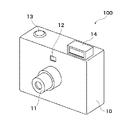
図1及び図2は、本発明の第1の実施の形態に係る撮像装置としてのデジタルスチルカメラの前面側及び背面側の外観を概略的に示す斜視図である。 FIG. 1 and FIG. 2 are perspective views schematically showing the appearance of the front side and the back side of the digital still camera as the imaging apparatus according to the first embodiment of the present invention.
図1及び図2において、デジタルスチルカメラ100は筐体10を有する。図1に示すように、筐体10の前面には、後述する図3における撮像部2を内包する鏡筒11と、対物レンズ及び接眼レンズで構成された光学ファインダ12とが配設されている。また、筐体10の上面には、レリーズボタン13と、ストロボ14とが配設されている。上記鏡筒11及びストロボ14は、筐体10の表面から突出可能に構成されている。図2に示すように、筐体10の背面には、電源スイッチ15と、ディスプレイ16と、ズームボタン18と、ディスプレイ16上で所定の操作を行うための3つの操作ボタン19a,19b,19cとが配設されている。ディスプレイ16は、画角を決定するための電子ファインダとしても機能する。
1 and 2, the digital
デジタルスチルカメラ100には、被写体の静止画像を取得する静止画撮影モードと、被写体の動画像を取得する動画撮影モードとがあり、ユーザが操作ボタン19a〜19cを操作することにより、いずれか一方の撮影モードを選択することができる。
The
図3は、図1及び図2のデジタルスチルカメラ100の内部構成を概略的に示すブロック図である。
FIG. 3 is a block diagram schematically showing an internal configuration of the digital
図3において、デジタルスチルカメラ100は、カメラマイコン1と、撮像部2と、コントラスト比較部3と、コントラスト測定部4と、発光部5と、画像表示部6と、記録部7と、データ加工部8と、被写体指示部9とを備える。カメラマイコン1は、各部2〜9と接続されており、各部2〜9は、カメラマイコン1の制御に基づいて、例えば以下のような動作を行う。撮像部2は、後述する撮影レンズ群や1つの撮像素子を含む。撮像部2と鏡筒11は撮影光学系を構成する。また、撮影レンズ群には、後述する主被写体にフォーカスを合わせるためのフォーカスレンズと、ズームボタン18の操作に応じて主被写体の拡大/縮小撮影を行うためのズームレンズとが含まれる。
In FIG. 3, a
撮像部2は、鏡筒11や撮影レンズ群の少なくとも1つのレンズ、例えばフォーカスレンズを移動させる(以下、「鏡筒駆動」という)。この鏡筒駆動の際、フォーカスレンズを移動させることにより、デジタルスチルカメラ100の撮影領域内にある複数の被写体の中から選択された主被写体にフォーカスが合わせられる。発光部5はストロボ14を駆動する。画像表示部6は、ディスプレイ16に所定の画像を表示する。記録部7は、上記撮像部2に含まれる1つの撮像素子が取得した画像を記録部7のメモリに画像データとして記録する画像取り込みを行う。データ加工部8は、複数の画像データの合成を行うことが可能である。被写体指示部9は、撮影領域内の複数の被写体のうちフォーカスを合わせたい被写体(以下、「主被写体」という)に関する情報をカメラマイコン1に入力する。主被写体は、ユーザが例えば上記電子ファインダ又は光学ファインダの表示範囲に対応する撮影領域から、部分領域(以下、「選択エリア」という)を設定することにより決定される。なお、選択エリアの設定に代えて、フォーカスレンズの焦点位置の変動可能な範囲内で選択された所定の焦点位置を設定してもよい。これらにより、カメラマイコン1は、主被写体を認識(特定)することができ、この特定された主被写体にフォーカスを合わせるべく撮像部2を駆動する。
The
なお、上記選択エリアや焦点位置の設定、即ち主被写体の選択は、ユーザが操作ボタン19a〜19cを操作しながらディスプレイ16上で行うことが好ましいが、これに限られることはない。例えば、ディスプレイ16がタッチパネル式であるときは、ユーザがタッチパネルを操作してもよい。また、操作ボタン19a〜19cに代えて十字キーやジョグダイヤル等が設けられている場合には、ユーザがこれらを用いてディスプレイ16上のカーソルを移動させてもよい。また、選択エリアの設定の際には、主被写体を取り囲むことが可能な大きさにサイズを変更可能な矩形のウインドウを用いることが好ましいが、これに限られることはない。
The selection area and the focus position, that is, the selection of the main subject, is preferably performed on the
また、カメラマイコン1は、例えば、公知の認識手段を利用することにより、撮像した画像における肌色占有率や、予め登録された人物の顔の色や服装の色に基づいて所定の人物を特定することもできる。さらに、カメラマイコン1は、特定した主被写体、例えば所定の人物を撮影領域内で追尾することも可能であり、これにより、デジタルスチルカメラ100は主被写体にフォーカスが合った画像を連続的に取得することができる。
Further, the camera microcomputer 1 specifies a predetermined person based on the skin color occupancy ratio in the captured image, the face color of the person registered in advance, or the color of clothes by using a known recognition unit, for example. You can also Furthermore, the camera microcomputer 1 can also track a specified main subject, for example, a predetermined person within the shooting region, whereby the digital
以下、デジタルスチルカメラ100の動画撮影モードにおける動作について説明する。
Hereinafter, the operation of the digital
デジタルスチルカメラ100は、ユーザが電源スイッチ15を操作することにより起動する。起動後、カメラマイコン1は、鏡筒11及びストロボ14を筐体10の表面から突出させることにより、デジタルスチルカメラ100を撮影可能状態にする。ユーザは、ディスプレイ16に表示されている被写体の画像を見ながら画角を決定する。このとき、必要に応じてズームボタン18を押下することによりズームレンズを駆動して撮影レンズ群の焦点位置を変動させる。その後、ユーザがレリーズボタン13を押下すると、デジタルスチルカメラ100において、鏡筒駆動が開始され、被写体の動画撮影が開始される。
The digital
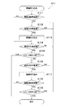
図4は、図1のデジタルスチルカメラ100によって実行される画像データ処理のフローチャートである。なお、本処理は、デジタルスチルカメラ100のカメラマイコン1の制御に従って実行される。
FIG. 4 is a flowchart of image data processing executed by the digital
図4において、ユーザのレリーズボタン13の押下に応じた動画撮影が開始されると、まず、ステップS11において、カメラマイコン1は、被写体の動画像を構成する多数の静止画像(フレーム)を取り込むために、図5を用いて詳述する画像取り込み処理を実行する。
In FIG. 4, when moving image shooting is started in response to the user pressing the
図5は、図4のステップS11で実行される画像取り込み処理の詳細を示すフローチャートである。 FIG. 5 is a flowchart showing details of the image capturing process executed in step S11 of FIG.
本画像取り込み処理では、撮像部2が、フォーカスレンズの焦点位置を変化させながら断続的な複数のタイミングで被写体の撮影を行うフォーカス・スキャンを実行する。このフォーカス・スキャンにより、複数の静止画像からなる被写体の静止画像集合体が画像データとして取得される。このとき、記録部7は、撮像部2が取得した各静止画像に対応する画像データを順次記録部7のメモリに記録する。
In this image capturing process, the
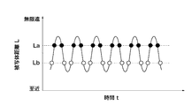
図6は、図5の処理で実行されるフォーカス・スキャンを説明するための図である。 FIG. 6 is a diagram for explaining the focus scan executed in the process of FIG.
図6は、連続して実行される複数回のフォーカス・スキャンの時間tと被写体距離Lとの関係を示している。ここで、被写体距離Lは、デジタルスチルカメラ100及び主被写体の位置間の距離を示しており、すなわち、デジタルスチルカメラ100及びフォーカスレンズの焦点位置間の距離に該当する。
FIG. 6 shows the relationship between the time t of a plurality of focus scans executed continuously and the subject distance L. Here, the subject distance L indicates the distance between the positions of the digital
複数回のフォーカス・スキャンでは、最至近合焦距離(以下、「至近」という)から無限遠合焦距離(以下、「無限遠」という)までの間で周期的にフォーカスレンズの焦点位置を変動させている。なお、至近では、被写体距離Lが最も短く、無限遠では、被写体距離Lが最も長い。1回のフォーカス・スキャンに必要な時間は、図6に示すような被写体距離Lの値の変動の半周期に対応するため、第1回目のフォーカス・スキャンは、被写体距離Lが至近又は無限遠から始まることが好ましい。 In multiple focus scans, the focal position of the focus lens varies periodically from the closest focus distance (hereinafter referred to as “closest”) to the infinity focus distance (hereinafter referred to as “infinity”). I am letting. It should be noted that the subject distance L is the shortest at the closest distance, and the subject distance L is the longest at infinity. Since the time required for one focus scan corresponds to a half cycle of fluctuation of the value of the subject distance L as shown in FIG. 6, the first focus scan is performed when the subject distance L is close or infinite. Preferably it begins.
また、各回のフォーカス・スキャンは、動画像モードにおいて被写体の動画像を撮像する際のフレームレート、例えば30fps(フレーム毎秒)に同期するように実行される。したがって、1回のフォーカス・スキャンは、各フレームの撮像が完了するまでの間に実行されるため、非常に高速で実行される。 In addition, each focus / scan is executed so as to be synchronized with a frame rate, for example, 30 fps (frame per second) when a moving image of a subject is captured in the moving image mode. Therefore, one focus scan is executed at a very high speed because it is executed until imaging of each frame is completed.
図5において、まず、ステップS111では、焦点位置が無限遠(無限遠合焦距離)であるか否かを判別する。該判別の結果、焦点位置が無限遠でないときは、ステップS114に進み、焦点位置が無限遠であるときは、ステップS112〜S113において図6の半周期に対応するフォーカス・スキャンを1回実行する。 In FIG. 5, first, in step S111, it is determined whether or not the focal position is at infinity (infinity focus distance). As a result of the determination, if the focal position is not infinite, the process proceeds to step S114. If the focal position is infinite, in steps S112 to S113, a focus scan corresponding to the half cycle in FIG. 6 is executed once. .
具体的には、焦点位置が無限遠側から至近側へ変動するように撮像部2は高速の鏡筒駆動を開始する。その結果、焦点位置は、図7に示すような複数の被写体距離L1〜L20のいずれかに該当する。なお、被写体距離L1〜L20は、図8を用いて後述するように、鏡筒駆動を停止するために予め設定されている。その結果、撮影光学系を構成する各部材が所定の光学配置になったか否かを判別する(ステップS112)。各部材が所定の光学配置になった場合には、鏡筒駆動を短時間だけ停止して、静止画撮影を行うことにより画像取り込みを行う(ステップS113)。画像の取り込みが終了した後、再度、鏡筒駆動を開始する。ステップS112〜S113の処理は、鏡筒駆動の結果、焦点位置が至近(最至近合焦距離)に到達するまで(ステップS114でYES)例えば20回に亘って繰り返し実行され、これにより、1回のフォーカス・スキャンが終了する。
Specifically, the
したがって、1回のフォーカス・スキャンでは、図7に示すように、各被写体距離L20〜L1に該当する焦点位置で撮影された20枚の静止画像で構成された1つの静止画像集合体700が取得される。ここで、1回のフォーカス・スキャンは、フレームレートに同期しているので、1回の画像取り込み(ステップS113)は、フレームレートの20倍の速度、即ち600fpsで行われている。 Therefore, in one focus scan, as shown in FIG. 7, one still image aggregate 700 composed of 20 still images captured at the focal positions corresponding to the subject distances L20 to L1 is acquired. Is done. Here, since one focus scan is synchronized with the frame rate, one image capture (step S113) is performed at a speed 20 times the frame rate, that is, 600 fps.
続いて、レリーズボタン13が押下されたか否かを判別し(ステップS115)、レリーズボタン13が押下されたときは、ステップS116〜S117において上記被写体距離Lの値の変動の半周期に対応するフォーカス・スキャンを1回実行する。具体的には、上記ステップS112〜S113の処理と同様のフォーカス・スキャンを実行する。
Subsequently, it is determined whether or not the
ここで、図6に示したように、連続して実行される2回のフォーカス・スキャンを円滑に実行すべく、ステップS116〜S117のフォーカス・スキャンにおける鏡筒駆動では、焦点位置が至近側から無限遠側へ変動させる。これにより、各被写体距離L1〜L20に該当する焦点位置で撮影された20枚の静止画像で構成された静止画像集合体700が取得される。鏡筒駆動の結果、焦点位置が無限遠に到達したときは(ステップS118でYES)、ステップS116〜S117のフォーカス・スキャンを終了して、ステップS119に進む。
Here, as shown in FIG. 6, in order to smoothly execute the two focus scans that are successively executed, in the lens barrel drive in the focus scans of steps S116 to S117, the focus position is changed from the closest side. Change to infinity side. As a result, a still
続くステップS119では、レリーズボタン13が押下されたか否かを判別する。該判別の結果、レリーズボタン13が押下されていないときは、上記連続した2回のフォーカス・スキャンを繰り返し実行すべく、ステップS112に戻り、一方、レリーズボタン13が押下されたときは、本処理を終了する。その後、図4のステップS12の処理にリターンする。
In a succeeding step S119, it is determined whether or not the
図5の処理によれば、複数回のフォーカス・スキャンにより、複数の静止画像集合体700を取得することができる。各静止画像集合体700は、図4の後述するステップS13において動画像の1コマとして抽出すべき少なくとも1枚の静止画像(以下、「フレーム」という)800を含む。このように取得された複数の静止画像集合体700は記録部7のメモリに保存される。必要に応じて、データサイズを小さくするために動画像データの圧縮を行ってもよい。
According to the processing of FIG. 5, a plurality of still image aggregates 700 can be acquired by a plurality of focus scans. Each still image aggregate 700 includes at least one still image (hereinafter referred to as “frame”) 800 to be extracted as one frame of a moving image in step S13 described later in FIG. The plurality of still image aggregates 700 acquired in this way are stored in the memory of the
また、図6に示すように、予め設定されている主被写体に対応する被写体距離Laが被写体距離Lとして設定されている場合には、複数の静止画像集合体700から被写体距離Laに対応するフレームが抽出される。このようにして抽出された複数のフレームからは、動画像が構築され、この動画像は動画像データとして記録部7のメモリに保存される。
As shown in FIG. 6, when the subject distance La corresponding to a preset main subject is set as the subject distance L, a frame corresponding to the subject distance La from a plurality of still image aggregates 700. Is extracted. A moving image is constructed from the plurality of frames thus extracted, and the moving image is stored in the memory of the
なお、図5の処理において、ステップS111及びステップS119の処理を省略してもよい。また、図5の処理では、ステップS115,S119においてレリーズボタン13の押下があると本処理を終了するように構成されているが、これに代えて、レリーズボタン13の押下中に動画撮影を行い、レリーズボタン13の押下の解除に伴って動画撮影を停止するようにしてもよい。
In the process of FIG. 5, the processes of step S111 and step S119 may be omitted. Further, in the processing of FIG. 5, this processing is configured to end when the
図8は、図5のステップS112,S116において鏡筒駆動を停止するために設定される被写体距離Lを説明するために用いる図である。 FIG. 8 is a diagram used for explaining the subject distance L set in order to stop the lens barrel drive in steps S112 and S116 of FIG.
図8において、被写体距離L10’は、図7における被写体距離L10の後方被写界深度を示し、被写体距離L9’は、被写体距離L9の後方被写界深度を示している。なお、各被写体距離Lの被写界深度は、フォーカスに合わせた(合焦させた)被写体の光軸上における前方及び後方に位置する他の被写体の画像にピンボケが実用上発生していないとみなせる範囲を示し、前方被写界深度及び後方被写界深度の和で表される。また、前方被写界深度及び後方被写界深度は、撮像部2に使用される撮像素子に応じて設定される許容錯乱円の直径(許容錯乱円径)を用いて決定される。この決定のために、許容錯乱円径に加えて撮影光学系の光学性能を示す数値、例えば焦点距離の値を用いてもよい。
In FIG. 8, the subject distance L10 'indicates the rear depth of field of the subject distance L10 in FIG. 7, and the subject distance L9' indicates the rear depth of field of the subject distance L9. It should be noted that the depth of field at each subject distance L is that there is practically no out-of-focus in the image of other subjects positioned forward and backward on the optical axis of the subject in focus (focused). This represents the range that can be considered, and is represented by the sum of the front depth of field and the rear depth of field. Further, the front depth of field and the rear depth of field are determined by using the diameter of an allowable confusion circle (allowable confusion circle diameter) set according to the image sensor used in the
また、図8に示すように、被写体距離L10は、その前方被写界深度が被写体距離L9の後方被写界深度を示す被写体距離L9’に一致するように設定される。同様に、被写体距離L10の後方被写界深度L10’は、被写体距離L11の前方被写界深度を示す被写体距離L11’に一致するように設定される。これにより、被写体距離L10の被写界深度は、被写体距離L9及びL11の被写界深度と連続する。したがって、被写体距離L10で撮影を行った場合には、被写体距離L9の後方被写界深度から被写体距離L11の前方被写界深度までの間に位置する被写体のピンボケが発生しないことになる。 Further, as shown in FIG. 8, the subject distance L10 is set so that the front depth of field coincides with the subject distance L9 'indicating the rear depth of field of the subject distance L9. Similarly, the rear depth of field L10 'of the subject distance L10 is set to coincide with the subject distance L11' indicating the front depth of field of the subject distance L11. Thereby, the depth of field at the subject distance L10 is continuous with the depth of field at the subject distances L9 and L11. Therefore, when shooting is performed at the subject distance L10, the subject located between the rear depth of field at the subject distance L9 and the forward depth of field at the subject distance L11 does not occur.
図8を用いて上述したように、被写体距離L1〜L20は、焦点位置の至近から無限遠までに亘って各被写体距離Lの被写界深度が連続するように実質的に等間隔(刻み間隔)で被写体距離Lの値として設定される。これにより、図5の処理で実行される各フォーカス・スキャンにおいて、被写体距離L1〜L20に該当する焦点位置で画像取り込みを行うだけで、実質的に全ての被写体距離Lを網羅した被写体の動画撮影を行うことができる。 As described above with reference to FIG. 8, the subject distances L1 to L20 are substantially equally spaced (incremental intervals) so that the depth of field of each subject distance L is continuous from the closest focus position to infinity. ) Is set as the value of the subject distance L. As a result, in each focus / scan executed in the processing of FIG. 5, moving images of a subject covering substantially all the subject distances L can be obtained simply by capturing an image at a focal position corresponding to the subject distances L1 to L20. It can be performed.
図4の処理に戻り、ステップS12では、ユーザは、所望の被写体、例えばピントが合っていない被写体(副被写体)を選択する。この選択は、ステップS11で取得した被写体距離Laに対応する動画像(図6に示す黒丸印に対応する複数の静止画像)をディスプレイ16上に再生しながら行うことが好ましい。ここで、選択された副被写体は、被写体距離Laとは異なる被写体距離L、例えば図6の被写体距離Lbに位置するため、ピントが合っていない。なお、被写体距離Laに対応する動画像に代えて、複数の静止画像集合体700を連続再生してもよい。 Returning to the processing of FIG. 4, in step S12, the user selects a desired subject, for example, a subject (sub-subject) that is not in focus. This selection is preferably performed while reproducing on the display 16 a moving image (a plurality of still images corresponding to the black circles shown in FIG. 6) corresponding to the subject distance La acquired in step S11. Here, since the selected sub-subject is located at a subject distance L different from the subject distance La, for example, the subject distance Lb in FIG. 6, it is not in focus. Note that a plurality of still image aggregates 700 may be continuously reproduced instead of the moving image corresponding to the subject distance La.
そこで、被写体指定部9は、副被写体にフォーカス(焦点,ピント)を合わせる合焦処理を行うために、副被写体に関する情報として、例えば被写体距離Lbの値やエリア情報(合焦領域情報)をカメラマイコン1に入力する。この結果、被写体距離Lの設定が、被写体距離Laから被写体距離Lbに変更される。 Therefore, the subject designating unit 9 uses, for example, the value of the subject distance Lb and area information (focused region information) as the information about the sub-subject in order to perform focusing processing for focusing on the sub-subject. Input to the microcomputer 1. As a result, the setting of the subject distance L is changed from the subject distance La to the subject distance Lb.
続くステップS13では、複数の静止画像集合体700の各々から、被写体距離Lbに対応するフレーム800を抽出する。具体的には、まず、コントラスト測定部4は、ステップS13で選択された合焦領域情報に基づいて、静止画像集合体700を構成する各静止画像の領域内で、副被写体及びその近傍を含むエリア(選択エリア)を特定する。次いで、図3のコントラスト測定部4は、選択エリア内の特徴的な画素、例えば人物の肌色に対応する部分の画素のコントラスト値を測定する。なお、コントラスト値は、ピントが合っている画素ほど高い。
In subsequent step S13, a
図9は、コントラスト測定部4によるコントラスト値の測定結果の一例を示す図である。
FIG. 9 is a diagram illustrating an example of the measurement result of the contrast value by the
図9に示す例では、コントラスト測定部4が測定した所定の画素に関して、被写体距離L1〜L20のうち被写体距離L10に対応するコントラスト値が最大になっている。このようにコントラスト値が最大になっている静止画像を、コントラスト比較部3はフレーム800として静止画像集合体700から抽出する。したがって、図9に示す例では、被写体距離L10が上記被写体距離Lbに該当する。なお、フレーム800は、コントラスト値が最大のものを抽出するとしたが、静止画像のデータサイズ又はその圧縮したデータのデータサイズが最大のものを抽出してもよい。
In the example illustrated in FIG. 9, the contrast value corresponding to the subject distance L10 among the subject distances L1 to L20 is the maximum for the predetermined pixel measured by the
このとき、抽出されなかった静止画像を記録部7のメモリから削除して該メモリの記憶可能な容量を増大させることが好ましい。なお、抽出することに代えて、該当する静止画像のコピーを作成してもよく、これにより、静止画像集合体700を確実に保存することができる。
At this time, it is preferable to delete the still image that has not been extracted from the memory of the
上述したように、コマ数に応じた数の静止画像集合体700から抽出された複数のフレーム800は、記録部7により、時系列順に並べられて新たな動画像として記録部7のメモリに記録される(ステップS16)。具体的には、図10に示すように、まず、複数の静止画像集合体700a,700b,700c,…,700nから複数のフレーム800a,800b,800c,…,800nが抽出される。続いて、これらのフレーム800a〜800nが時系列順に並べられ新たな動画像1000が構築される。この動画像1000は、動画像データとして記録部7のメモリに保存される。その後、デジタルスチルカメラ100は、撮影待機状態となり、本処理を終了する。
As described above, the plurality of
図4及び図5の処理によれば、1回のフォーカス・スキャン中に複数の被写体距離Lに該当する焦点位置で静止画撮影を高速で行うことにより静止画像集合体700を取得する(ステップS11及び図5)。したがって、静止画像集合体700は、主被写体にフォーカスが合った静止画像と、少なくとも1つの副被写体にフォーカスが合った静止画像とを含んでいることになる。これにより、所望の被写体(主被写体又は副被写体)が鮮明に撮影された画像を確実に取得することができる。
4 and 5, the
また、本処理によれば、画像取り込み後に、ユーザは、静止画像集合体700からフレーム800を抽出すべく(ステップS13)、所望の被写体にフォーカスを被写体深度の範囲内で完全に合わせることが可能である。これにより、撮影開始時にユーザが所望の被写体にフォーカスを合わせる必要をなくすことができる。したがって、フォーカスを合わせるべき被写体の選択に失敗した結果、所望の被写体がピンボケするという従来技術の課題を確実に解決することができ、もって、所望の被写体に発生するピンボケという概念をなくすことができる。
Further, according to this process, after capturing an image, the user can completely focus on a desired subject within the range of the subject depth in order to extract the
さらに、デジタルスチルカメラ100を、フォーカスレンズの焦点位置を変動させながら高速撮影を行うフォーカス・スキャンを実行可能に構成するだけで所望の被写体が鮮明に撮影された画像を含む静止画像集合体700を取得することができる。その結果、例えば、高価な他の撮像素子及びそれに付随する部品を撮像部2に設ける必要がなくなり、もって、デジタルスチルカメラ100のコストの増大を抑制することができると共に、その大型化を防止することができる。
Further, the digital
また、新たな動画像1000を構築するために、静止画像集合体700からフレーム800を抽出する(ステップS13)だけであるので、抽出すべきフレーム800を変更することにより、他の新たな動画像を容易に作成することができる。その結果、ユーザによる画像データの編集性を向上させることができる。例えば、主被写体とデジタルスチルカメラ100との相対的な位置を示す被写体距離が刻々と変化する場合であっても、該主被写体へのフォーカスを容易に追従させた動画像データを容易に作成することができる。
Further, since only the
また、上記実施の形態では、フォーカス・スキャンを動画撮影モードであるときに適用したが、静止画撮影モードであるとき、即ち被写体の静止画像を撮影する際に適用してもよい。この場合、撮影終了後に、静止画像集合体700の中から、所望の被写体にフォーカスが合っている画像を抽出又は選択するだけで、所望の被写体が鮮明に撮影された静止画像を確実に取得することができる。したがって、ユーザが撮影のタイミングを逃した結果、所望の被写体がピンボケするという従来技術の課題を確実に解決することができ、もって、所望の被写体に発生するピンボケという概念をなくすことができる。
In the above embodiment, the focus scan is applied when the moving image shooting mode is set. However, the focus scanning may be applied when the still image shooting mode is set, that is, when a still image of the subject is shot. In this case, after the shooting is completed, a still image in which the desired subject is clearly captured can be surely acquired by extracting or selecting an image in which the desired subject is in focus from the
また、本実施の形態では、静止画像集合体1000から動画像用に抽出されるフレームの数(コマ数)を変更したり、フレームを編集したりすることができる。これらを第1及び第2の変形例として説明する。 In the present embodiment, the number of frames (number of frames) extracted for moving images from the still image aggregate 1000 can be changed or the frames can be edited. These will be described as first and second modifications.
図11は、本実施の形態の第1の変形例によって取得される動画像を示す図である。 FIG. 11 is a diagram showing a moving image acquired by the first modification of the present embodiment.
図11に示す複数の静止画像から構築された動画像1100は、図10の動画像1000のコマ数を増大させたものである。具体的には、静止画像集合体700a〜700nからフレーム810a,810b,810c,…,810nが更に抽出されている。すなわち、各静止画像集合体からは2枚のフレームが抽出される。この場合、抽出すべき2枚のフレーム及びその被写体距離Lの値は、例えば、ユーザがディスプレイ16上で2つの被写体、例えば人物と背景とを選択することにより決定される。ここで、各静止画像集合体から3枚以上のフレームを抽出してもよい。
A moving
また、動画像1100のコマ数は、図10の動画像1000のコマ数の2倍である。したがって、動画像1100を動画像1000と同様の再生速度で再生した場合、人物にピントが合った静止画像と背景にピントが合った静止画像とが交互に、短時間の間に即ち高速で再生される。その結果、ユーザが選択した被写体の双方にピントが合ったように視認される動画像を取得することができる。
Further, the number of frames of the moving
なお、動画像1100から不必要なフレームを削除することも可能であり、これにより、動画像1100の記憶に必要な記録部7のメモリの容量を削減することができる。
It is also possible to delete unnecessary frames from the moving
図12は、本実施の形態の第2の変形例によって取得される動画像を示す図である。 FIG. 12 is a diagram showing a moving image acquired by the second modification of the present embodiment.
図12に示す複数の静止画像から構築された動画像1200は、静止画像集合体700a〜700nからフレーム800a〜800n,810a〜810nを抽出したものである。動画像1200では、フレーム800a〜800n,810a〜810nがそれぞれデータ加工部8によって合成されて合成フレーム820a,820b,820c,…,820nが構築されている点が動画像1100と相違する。
A moving
図13は、図12の動画像1200を取得するために実行される画像データ処理のフローチャートである。なお、本処理は、図4の処理と大部分が共通するので、異なる部分を主に説明する。
FIG. 13 is a flowchart of image data processing executed for obtaining the moving
図13において、ステップS21,S22,S23,S26の処理は、それぞれ、図4のステップS11,S12,S13,S16の処理と同一である。 In FIG. 13, the processes of steps S21, S22, S23, and S26 are the same as the processes of steps S11, S12, S13, and S16 of FIG.
ステップS24では、データ加工部8が静止画像集合体700a〜700nの各々から抽出された2つのフレームを合成する。続くステップS25では、全ての静止画像集合体から抽出したフレームの合成が終了したか否かを判別する。ステップS25の判別の結果、終了していないときは、ステップS22の処理に戻り、ステップS22〜S24の処理を繰り返す。なお、ステップS22において、さらに、他の副被写体を選択してもよい。
In step S24, the
フレームの合成が終了したときは(ステップS25でYES)、ステップS26で、新たに構築された動画像1200を動画像データとして保存する。そして、本処理を終了する。
When frame composition is completed (YES in step S25), the newly constructed moving
図13の処理によれば、1つの静止画像集合体から抽出された2つのフレームが合成されて合成フレームが構築される。合成フレーム820a〜820nから構築された動画像1200(図12)は、コマ数が図10の動画像1000のコマ数と同一であり、図11の動画像1100のコマ数の2分の1である。したがって、図11の動画像1100からフレームを削除することなく、動画像1200の記憶に必要な記録部7のメモリの容量を削減することができる。
According to the process of FIG. 13, two frames extracted from one still image aggregate are combined to construct a combined frame. The moving image 1200 (FIG. 12) constructed from the
また、動画像1200を動画像1100と同一の再生速度で再生した場合、動画像1100とは異なり、人物にピントが合った静止画像と背景にピントが合った静止画像とが交互に再生されることがない。その結果、動画像1100よりも再生時の違和感がない、即ち滑らかな動画像を取得することができる。
Also, when the moving
なお、上記第2の変形例では、1つの静止画像集合体から抽出された2つのフレームを合成したが、この場合、合成される複数のフレームは、時系列順であることが好ましい。なお、時系列順に限られることはなく、例えば、複数の静止画像集合体から抽出された、互いに異なる焦点位置(被写体距離Lの値)で撮像されたフレーム、具体的には図12のフレーム800bと810cとを合成してもよい。
In the second modified example, two frames extracted from one still image aggregate are synthesized. In this case, it is preferable that the plurality of frames to be synthesized are in chronological order. The order is not limited to time series. For example, frames extracted from a plurality of still image aggregates and captured at different focal positions (values of subject distance L), specifically, a
なお、上記第1の変形例及び第2の変形例において、フレーム800a〜800n,810a〜810nを記録部7のメモリに保存しておくことにより、動画像1100,1200を容易に構築することができる。
In the first and second modifications, the moving
以下、本発明の第2の実施の形態を説明する。 The second embodiment of the present invention will be described below.
本実施の形態に係る撮像装置としてのデジタルスチルカメラは、上記第1の実施の形態に係る撮像装置(図1のデジタルスチルカメラ)の撮影光学系(撮像部2)の構成が異なるのみであり、その他の構成及び構成要素は同一であるので、それらの説明を省略する。具体的には、本実施の形態によるデジタルスチルカメラは、撮像部が複数の撮像素子を備える点で、第1の実施の形態による撮像部2とは異なる。
The digital still camera as the imaging apparatus according to the present embodiment is different only in the configuration of the imaging optical system (imaging unit 2) of the imaging apparatus (digital still camera in FIG. 1) according to the first embodiment. Since other configurations and components are the same, the description thereof is omitted. Specifically, the digital still camera according to the present embodiment is different from the
図14は、第2の実施の形態に係る撮像装置としてのデジタルスチルカメラの撮影光学系の構成を概略的に示すブロック図である。 FIG. 14 is a block diagram schematically showing a configuration of a photographing optical system of a digital still camera as an image pickup apparatus according to the second embodiment.
本実施の形態によるデジタルスチルカメラの撮像部2’は、図14に示すように、複数のレンズが配置されており、第1光学系と第2光学系とを構成する。 As shown in FIG. 14, the imaging unit 2 'of the digital still camera according to the present embodiment includes a plurality of lenses and constitutes a first optical system and a second optical system.
第1光学系は、図14に示す被写体光路に沿って配置された、光学レンズ群21と、ビームスプリッタ22と、フォーカスレンズ23aと、CCD等から成る撮像素子24aとを備える。光学レンズ群21は、3つのレンズ21a,21b,21cとから構成されている。ビームスプリッタ22は、被写体からの光を2つに分光し、一方の光が撮像素子24aに入射する。
The first optical system includes an
第2光学系は、光学レンズ群21と、ビームスプリッタ22と、フォーカスレンズ23bと、CCD等から成る撮像素子24bとを備える。したがって、第2光学系は、光学レンズ群21及びビームスプリッタ22を第1光学系と共有する。撮像素子24bには、ビームスプリッタ22によって分光された他方の光が入射する。
The second optical system includes an
撮像素子24a及び撮像素子24bは、第1の実施の形態で説明したような動画撮影モードにおいてフォーカス・スキャニングで画像を連続的に取り込む。このために、撮像素子24a,24bには、無限遠から至近までの焦点位置に該当する全被写体距離Lのうち、それぞれが画像取り込み可能な被写体距離Lの範囲、即ち焦点位置の変動範囲が予め設定される。これにより、2つの撮像素子24a,24bは、同時刻に、互いに異なる焦点位置(被写体距離Lの値)で撮像することが可能となる。
The
焦点位置の範囲の設定、即ちフォーカスレンズ23a,23bの移動範囲の設定は、無限遠から至近までの間において、例えば中間の被写体距離Lの値(以下、「中間被写体距離Lc」という)を設定することにより行われる。これにより、撮像素子24a及び撮像素子24bは、設定されたフォーカスレンズ23a,23bの移動範囲に応じてその画像取り込み可能なエリアが撮影範囲内で分配される。
The setting of the focus position range, that is, the setting of the movement range of the
図15は、図14の2つの撮像素子24a及び撮像素子24bが画像取り込み可能な被写体距離の値の範囲を説明するための図である。
FIG. 15 is a diagram for explaining a range of subject distance values that can be captured by the two
図15において、縦軸は被写体距離L即ち焦点位置を示しており、横軸は時間tを示している。図15に示す被写体距離Laは、撮像素子24aが画像取り込み可能な被写体距離の範囲内で第1の主被写体を撮像すべく設定された焦点位置を示している。撮像素子24aは、図15に示すように、全被写体距離Lのうち、中間被写体距離Lcから無限遠までに該当する焦点位置の変動範囲内においてフォーカス・スキャニングを行う。
In FIG. 15, the vertical axis indicates the subject distance L, that is, the focal position, and the horizontal axis indicates time t. A subject distance La shown in FIG. 15 indicates a focal position set to capture the first main subject within the range of the subject distance that can be captured by the
また、同様に、被写体距離La’は、撮像素子24bが画像取り込み可能な被写体距離の範囲内で第2の主被写体を撮像すべく設定された焦点位置を示している。撮像素子24bは、図15に示すように、全被写体距離Lのうち、至近から中間被写体距離Lcまでに該当する焦点位置の変動範囲内においてフォーカス・スキャニングを行う。
Similarly, the subject distance La ′ indicates the focal position set to image the second main subject within the range of the subject distance that can be captured by the
したがって、撮像素子24a,24bは、中間被写体距離Lcを境界としてフォーカス・スキャニング可能な焦点位置の変動範囲が重複しないように又は中間被写体距離Lcに該当する焦点位置においてのみ重複するように分配されている。
Therefore, the
撮像素子24aが取り込んだ静止画像と撮像素子24bが取り込んだ静止画像は同期をとりながら記録部7の単一のメモリに保存される。保存された画像には、上述した第1の実施の形態と同様の処理が施される。これにより、撮像素子24aによる静止画像集合体又は撮像素子24bによる静止画像集合体のいずれか一方から、上述した第1の実施の形態と同様に、所望の被写体が鮮明に撮影された画像を確実に取得することができる。
The still image captured by the
第2の実施の形態によれば、2つの撮像素子24a,24bにはフォーカス・スキャニング可能な焦点位置の変動範囲が分配されている。その結果、第1の実施の形態に対して画像の取り込み時間を半減させることにより、フォーカス・スキャニングに要する時間(周期)を半減させることができる。又は、第1の実施の形態とフォーカス・スキャニングの周期を同一にすることにより、2倍の画像の取り込み時間を確保することができる。また、各撮像素子24a,24bが各々の解像度で撮像するので、動画像の解像度を向上させることができる。
According to the second embodiment, the two
なお、第2の実施の形態において、撮像素子24a,24bとしては、感度が非常に高い即ち超高感度の撮像素子を用いることが好ましい。また、光学レンズ群21を構成するレンズ21a,21b,21cやフォーカスレンズ23a,23bとしては、明るいレンズ即ち集光性の高いレンズを用いることが好ましい。これらにより、1枚の画像を取り込む際の時間当たりの光量を増大させることができる。
In the second embodiment, it is preferable to use, as the
以下、第2の実施の形態の変形例を説明する。 Hereinafter, a modification of the second embodiment will be described.
図16は、第2の実施の形態の変形例において、2つの撮像素子24a及び撮像素子24bが画像取り込みを行う被写体距離の値の範囲を説明するための図である。
FIG. 16 is a diagram for explaining a range of subject distance values in which two
本変形例では、撮像素子24aは、予め設定された第1の主被写体を所定の撮影範囲内で追尾可能に構成されており、これにより、撮影開始前に予め決定した第1の主被写体及びその近傍を含む撮影領域に関して鮮明な画像の取り込みを継続することができる。
In the present modification, the
図16に示す被写体距離Laは、撮影範囲内で撮像素子24aが第1の主被写体を追尾するために撮影開始前に設定された焦点位置を示している。なお、図16に示す例は、被写体距離Lの値が大きく変動しなかった場合、即ち第1の被写体が大きく移動しなかった場合を示している。したがって、フォーカスレンズ23aの焦点位置も大きく変動していない。
A subject distance La shown in FIG. 16 indicates a focal position set before the start of photographing so that the
ここで、フォーカスレンズ23aの焦点位置は大きく変動しないことが好ましい。これにより、撮像素子24aによって撮像された撮影領域内の被写体の画像をリアルタイムで、即ち動画像としてディスプレイ16に表示している場合に、ユーザはディスプレイ16で撮影状況を確認しながら撮影を行うことができる。
Here, it is preferable that the focal position of the
また、被写体距離La’は、撮像素子24bが撮像素子24aの撮影領域以外の撮影領域において第2の被写体を撮像すべく撮影開始前に設定された焦点位置を示している。撮像素子24bは、例えば、図16に示すように、全被写体距離Lのうち、至近から被写体距離Laまでに該当する焦点位置の変動範囲内でフォーカス・スキャニングを行う。
The subject distance La ′ indicates a focal position set before the start of shooting so that the
したがって、本変形例において、撮像素子24a,24bのフォーカスレンズ23a,23bは、被写体距離Laを境界としてフォーカス・スキャニング可能な焦点位置の変動範囲が分配されている。
Therefore, in this modification, the
なお、撮像素子24a,24bがフォーカス・スキャニング可能なフォーカスレンズ23a,23bの焦点位置の変動範囲は重複してもよい。その理由は、フォーカスレンズ23a,23bの焦点位置の変動範囲が重複する重複時間は極めて短い時間である場合が多く、最終的に動画像として抽出される複数のフレームが上記重複時間内に撮像された静止画像に該当する可能性が低いからである。したがって、動画再生時において、動画像の滑らかさをほとんど損なうことはない。
Note that the focal ranges of the
最終的には、撮像素子24aが取り込んだ静止画像と撮像素子24bが取り込んだ静止画像は同期をとりながら記録部7の単一のメモリに保存される。これにより、撮像素子24aが撮影した第1の被写体の鮮明な画像を確実に取得することができるだけでなく、撮像素子24bによる静止画像集合体から、上述した第1の実施の形態と同様に、所望の被写体が鮮明に撮影された画像を確実に取得することができる。
Finally, the still image captured by the
なお、図16は、第1の被写体の被写体距離Laが大きく変動しない場合を示しているが、第1の被写体の被写体距離Laは大きく変動してもよい。例えば、第1の被写体の被写体距離に該当する焦点位置が至近側へ変動した後に、再度、無限遠側に変動してもよい。この場合、第1光学系は、上述したように、第1の主被写体を追尾することにより、第1の主被写体の被写体距離に該当する焦点位置での画像の取り込みを継続する。一方、第2光学系は、撮像素子24aが画像取り込み可能な焦点位置の変動範囲と重複しながらフォーカス・スキャンを継続する。
FIG. 16 shows a case where the subject distance La of the first subject does not vary greatly, but the subject distance La of the first subject may vary greatly. For example, the focus position corresponding to the subject distance of the first subject may change to the infinity side again after changing to the close side. In this case, as described above, the first optical system continues to capture an image at the focal position corresponding to the subject distance of the first main subject by tracking the first main subject. On the other hand, the second optical system continues focus / scan while overlapping with the fluctuation range of the focal position where the
本変形例において、第2光学系が取得した静止画像集合体の少なくとも1枚の静止画像を、第1光学系が追尾した第1の被写体の静止画像集合体に追加してもよい。また、これに代えて、第2光学系が取得した静止画像集合体から所望の被写体にフォーカスが合ったフレームと、第1光学系が撮影した第1の被写体の少なくとも1枚の静止画像とを合成してもよい。 In this modification, at least one still image of the still image aggregate acquired by the second optical system may be added to the still image aggregate of the first subject tracked by the first optical system. Alternatively, a frame in which a desired subject is focused from the still image aggregate acquired by the second optical system and at least one still image of the first subject captured by the first optical system are included. You may synthesize.
なお、第2の実施の形態及びその変形例では、撮像素子の数を2つにしたが、3つ以上であってもよい。これにより、全被写体距離Lに該当する焦点位置の無限遠から至近までの変動範囲内でフォーカス・スキャンするのに要する時間(スキャン時間)をさらに短縮化させることができる。また、3つの撮像素子を用いる場合、各撮像素子に対して固有の色、例えばR(赤),G(緑),B(青)のいずれかを対応させ、これにより、各撮像素子が取得した各色の静止画像を合成してもよい。 In the second embodiment and its modification, the number of image sensors is two, but may be three or more. As a result, it is possible to further shorten the time (scanning time) required to perform focus / scan within the fluctuation range of the focal position corresponding to the total object distance L from infinity to the nearest. When three image sensors are used, each image sensor is associated with a unique color, for example, R (red), G (green), or B (blue). The still images of each color may be combined.
なお、上述した第1及び第2の実施の形態において、デジタルスチルカメラ100は、以下に説明するような動画像パンフォーカス機能を有するものであってもよい。
In the first and second embodiments described above, the digital
図17は、図1のデジタルスチルカメラ100の動画像パンフォーカス機能を説明するために用いる撮影領域を示す図である。
FIG. 17 is a diagram showing a shooting area used to explain the moving image pan focus function of the digital
デジタルスチルカメラ100が例えば三脚などで固定されている場合には、図17に示すように、ディスプレイ16の表示領域に対応する撮影領域1700も固定される。図17に示す例では、撮影領域1700が、部分領域1720a,1720b,1720cを含む12個の部分領域に分割されている。部分領域1720a,1720b,1720cには、それぞれ、植物画像1710a,1710b,1710cが表示されている。
When the digital
図17において、ユーザは、ディスプレイ16上で、主被写体を選択する際に部分領域を指定する。これにより、部分領域内の主被写体にピントが最も合っている画像を取得することができる。
In FIG. 17, the user designates a partial area on the
具体的には、ユーザが、撮影領域1700の中央にある植物画像1710bに対応する被写体、即ち植物にピントを合わせたい場合、部分領域1720bを指定する。これにより、植物画像1710bに対応する植物にピントが合った動画像を取得することができる。
Specifically, when the user wants to focus on the subject corresponding to the
これに加えて、被写体距離が短い、即ち手前の植物(植物画像1710a)、及び、被写体距離が長い、即ち後方の植物(植物画像1710c)の双方にもピントを合わせたい場合には、部分領域1720bだけでなく部分領域1720a,1720cも指定される。
In addition to this, when it is desired to focus on both the short object distance, that is, the front plant (
さらに、全ての部分領域を指定することにより、撮影領域内の全ての被写体にピントがあったパンフォーカス的な動画像を取得することが可能となる(動画像パンフォーカス機能)。この動画像パンフォーカス機能は、撮影領域1700において全ての部分領域を設定することにより自動的に設定される。
Furthermore, by specifying all the partial areas, it is possible to acquire a pan-focus-like moving image in which all subjects in the shooting area are in focus (moving image pan-focus function). This moving image pan focus function is automatically set by setting all partial areas in the
また、図17に示すように静的な被写体を撮影しているときに、撮影領域1700内に飛び込んできた動的な被写体にピントを合わせたい場合には、上述した認識手段によってその動的な被写体を追尾してもよい。
Also, as shown in FIG. 17, when a static subject is photographed, when it is desired to focus on a dynamic subject that has jumped into the photographing
なお、上述した第1及び第2の実施の形態及びそれらの変形例において、図5の処理では鏡筒駆動を行うとしたが、焦点位置を変動させることが可能であれば、鏡筒駆動を行わなくてもよい。 In the above-described first and second embodiments and their modifications, the lens barrel drive is performed in the process of FIG. 5, but if the focal position can be changed, the lens barrel drive is performed. It does not have to be done.
また、上記実施の形態では、フレーム方式について説明したが、フィールド方式であっても同様に本発明を適用することができる。フィールド方式には、NYSC(National TV Standards Committee)方式や(Phase Alternation Line)方式がある。また、デジタルスチルカメラ100は、1回のフォーカス・スキャンで20回の静止画撮影を高速で行うとしたが、静止画撮影の回数(ステップ数)は20回でなくてもよい。例えば、静止画撮影の回数を20回よりも多くすることにより、解像度をさらに向上させてもよいし、一方、20回よりも少なくすることにより、フォーカス・スキャンの速度をさらに向上させて、取り込まれる画像の1枚毎の明るさを向上させてもよい。
In the above embodiment, the frame method has been described. However, the present invention can be similarly applied to the field method. Field systems include the NYSC (National TV Standards Committee) system and the (Phase Alternation Line) system. Further, although the digital
また、上記実施の形態において、デジタルスチルカメラ100は、ストロボ14及び光学ファインダ12を備えているとしたが、ストロボ14及び光学ファインダ12の一方又は双方を備えていなくてもよい。
In the above-described embodiment, the digital
また、上記実施の形態において、記録部7のメモリは、いかなるものであってもよく、複数であってもよい。例えば、削除される可能性が高い静止画像集合体700a,700b,700c,…,700nを揮発性記憶媒体に格納し、保存される可能性が高い動画像1000,1100,1200をSDカードやCF(コンパクトフラッシュ(登録商標))カードなどの可搬性記憶媒体に格納することが好ましい。
Moreover, in the said embodiment, the memory of the
上記実施の形態では、デジタルスチルカメラ100の動画撮影モードを例示しているが、本発明をデジタルスチルカメラ100の静止画撮影モードに適用してもよい。また、上記実施の形態に係る撮像装置は、デジタルスチルカメラであるとしたが、デジタルビデオカメラ(DVC)などであってもよい。
In the above embodiment, the moving image shooting mode of the digital
また、本発明の目的は、上述した各実施の形態の機能を実現するソフトウェアのプログラムコードを記録した記憶媒体を、システム或いは装置に供給し、そのシステム或いは装置のコンピュータ(又はCPUやMPUなど)が記憶媒体に格納されたプログラムコードを読み出して実行することによっても達成される。 Also, an object of the present invention is to supply a storage medium storing software program codes for realizing the functions of the above-described embodiments to a system or apparatus, and a computer (or CPU or MPU) of the system or apparatus. Is also achieved by reading and executing the program code stored in the storage medium.
この場合、記憶媒体から読み出されたプログラムコード自体が上記各実施の形態の機能を実現することになり、そのプログラムコード及び該プログラムコードを記憶した記憶媒体は本発明を構成することになる。 In this case, the program code itself read from the storage medium realizes the functions of the above embodiments, and the program code and the storage medium storing the program code constitute the present invention.
また、プログラムコードを供給するための記憶媒体としては、例えば、フロッピー(登録商標)ディスク、ハードディスク、光磁気ディスク、CD−R、CD−RW、DVD−ROM、DVD−RAM、DVD−RW、DVD+RW等の光ディスク、磁気テープ、不揮発性のメモリカード、ROMなどを用いることができる。又は、プログラムコードをネットワークを介してダウンロードしてもよい。 Examples of the storage medium for supplying the program code include a floppy (registered trademark) disk, a hard disk, a magneto-optical disk, a CD-R, a CD-RW, a DVD-ROM, a DVD-RAM, a DVD-RW, and a DVD + RW. Such optical disks, magnetic tapes, nonvolatile memory cards, ROMs, and the like can be used. Alternatively, the program code may be downloaded via a network.
また、コンピュータが読み出したプログラムコードを実行することにより、上記各実施の形態の機能が実現されるだけでなく、そのプログラムコードの指示に基づき、コンピュータ上で稼動しているOS(オペレーティングシステム)などが実際の処理の一部又は全部を行い、その処理によって前述した各実施の形態の機能が実現される場合も含まれる。 Further, by executing the program code read by the computer, not only the functions of the above embodiments are realized, but also an OS (operating system) running on the computer based on the instruction of the program code Includes a case where part or all of the actual processing is performed and the functions of the above-described embodiments are realized by the processing.
更に、記憶媒体から読み出されたプログラムコードが、コンピュータに挿入された機能拡張ボードやコンピュータに接続された機能拡張ユニットに備わるメモリに書込まれた後、そのプログラムコードの指示に基づき、その機能拡張ボードや機能拡張ユニットに備わるCPUなどが実際の処理の一部又は全部を行い、その処理によって前述した各実施の形態の機能が実現される場合も含まれる。 Further, after the program code read from the storage medium is written into a memory provided in a function expansion board inserted into the computer or a function expansion unit connected to the computer, the function is determined based on the instruction of the program code. This includes a case where a CPU or the like provided in an expansion board or a function expansion unit performs part or all of actual processing, and the functions of the above-described embodiments are realized by the processing.
1 カメラマイコン
2 撮像部
3 コントラスト比較部
4 コントラスト測定部
6 画像表示部
7 記録部
8 データ加工部
9 被写体指示部
11 鏡筒
21 光学レンズ群
23a,23b フォーカスレンズ
24a,24b 撮像素子
100 デジタルスチルカメラ
700,700a〜700n
800,800a〜800n,810a〜810n フレーム
820a〜820n 合成フレーム
1000,1100,1200 動画像
DESCRIPTION OF SYMBOLS 1
800, 800a to 800n, 810a to
Claims (6)
フォーカスレンズを移動させるフォーカスレンズ制御手段と、
前記画像信号出力手段からの画像信号に基づく画像を記憶する記憶手段と、
前記フォーカスレンズ制御手段により前記フォーカスレンズを予め決められた範囲で移動させることで異なる距離にフォーカスを合わせた複数の画像を取得して前記記憶手段に記憶する記憶動作を周期的に繰り返し、当該記憶した複数の画像の1周期分からユーザの選択に基づいて第1の被写体にフォーカスを合わせた画像又は第2の被写体にフォーカスを合わせた画像を1フレームとして取得する取得手段と、
前記1フレームとして取得した画像を並べることにより動画像として構築し、前記動画像を前記記憶手段に保存させる動画像構築手段と、
前記動画像構築手段によって構築された動画像が前記記憶手段に保存された後に、前記ユーザによって選択されなかった前記第1の被写体にフォーカスを合わせた画像又は前記第2の被写体にフォーカスを合わせた画像を動画像として前記動画像構築手段に構築させることができるように、前記周期的に繰り返された前記記憶動作によって取得された複数の画像を1周期分毎に静止画像集合体として前記記憶手段に保存させる静止画像保存手段と、を有することを特徴とする撮像装置。 Image signal output means for outputting an image signal in response to light from the subject;
A focus lens control means for moving the focus lens;
Storage means for storing an image based on the image signal from the image signal output means;
The memory operation of the focus lens plurality of images in focus at different distances by moving in a predetermined range to get stored in the storage unit to repeatedly periodically by the focus lens control unit, an acquisition unit configured to acquire a plurality of images in focus focus image or the second object combined with the first object on the basis of the one period to the user's selection of the image corresponding stored as 1 frame,
A moving image constructing unit configured to construct a moving image by arranging the images acquired as the one frame, and storing the moving image in the storage unit;
After the moving image constructed by the moving image constructing unit is stored in the storage unit, the focused image is focused on the first subject or the second subject not selected by the user. In order to allow the moving image construction means to construct an image as a moving image, the storage means as a still image aggregate for a plurality of images acquired by the storage operation repeated periodically. An image pickup apparatus comprising: a still image storage unit that stores the image.
前記フォーカスレンズ制御ステップにより前記フォーカスレンズを予め決められた範囲で移動させることで異なる距離にフォーカスを合わせた複数の画像を取得して前記記憶手段に記憶する記憶動作を周期的に繰り返し、当該記憶した複数の画像の1周期分からユーザの選択に基づいて第1の被写体にフォーカスを合わせた画像又は第2の被写体にフォーカスを合わせた画像を1フレームとして取得する取得ステップと、
前記1フレームとして取得した画像を並べることにより動画像として構築し、前記動画像を前記記憶手段に保存させる動画像構築ステップと、
前記動画像構築ステップによって構築された動画像が前記記憶手段に記憶された後に、前記ユーザによって選択されなかった前記第1の被写体にフォーカスを合わせた画像又は前記第2の被写体にフォーカスを合わせた画像を動画像として構築することができるように、前記周期的に繰り返された前記記憶動作によって取得された複数の画像を1周期分毎に静止画像集合体として前記記憶手段に保存させる静止画像保存ステップと、を有することを特徴とする撮像方法。 An image signal output step for outputting an image signal according to light from the subject, a focus lens control step for moving the focus lens, and a memory for storing an image based on the image signal output from the image signal output step in a storage means An imaging method for acquiring an image using steps,
Just repeat storage operation of storing and acquiring a plurality of images in focus at different distances by moving in a predetermined range of the focus lens by the focus lens control step in the storage unit periodically, an acquisition step of acquiring a plurality of images in focus focus image or the second object combined with the first object on the basis of the one period to the user's selection of the image corresponding stored as 1 frame,
Constructing a moving image by arranging the images acquired as the one frame, and storing the moving image in the storage unit;
After the moving image constructed in the moving image constructing step is stored in the storage means, the image focused on the first subject that has not been selected by the user or focused on the second subject Still image storage for storing a plurality of images acquired by the periodically repeated storage operation as a still image aggregate in the storage means for each period so that an image can be constructed as a moving image And an imaging method comprising: steps .
前記撮像方法は、
前記フォーカスレンズ制御ステップにより前記フォーカスレンズを予め決められた範囲で移動させることで異なる距離にフォーカスを合わせた複数の画像を取得して前記記憶手段に記憶する記憶動作を周期的に繰り返し、当該記憶した複数の画像の1周期分からユーザの選択に基づいて第1の被写体にフォーカスを合わせた画像又は第2の被写体にフォーカスを合わせた画像を1フレームとして取得する取得ステップと、
前記1フレームとして取得した画像を並べることにより動画像として構築し、前記動画像を前記記憶手段に保存させる動画像構築ステップと、
前記動画像構築ステップによって構築された動画像が前記記憶手段に記憶された後に、前記ユーザによって選択されなかった前記第1の被写体にフォーカスを合わせた画像又は前記第2の被写体にフォーカスを合わせた画像を動画像として構築することができるように、前記周期的に繰り返された前記記憶動作によって取得された複数の画像を1周期分毎に静止画像集合体として前記記憶手段に保存させる静止画像保存ステップと、を有することを特徴とするプログラム。 An image signal output step for outputting an image signal according to light from the subject, a focus lens control step for moving the focus lens, and a memory for storing an image based on the image signal output from the image signal output step in a storage means A program for causing a computer to execute an imaging method for acquiring an image using steps,
The imaging method is:
Just repeat storage operation of storing and acquiring a plurality of images in focus at different distances by moving in a predetermined range of the focus lens by the focus lens control step in the storage unit periodically, an acquisition step of acquiring a plurality of images in focus focus image or the second object combined with the first object on the basis of the one period to the user's selection of the image corresponding stored as 1 frame,
Constructing a moving image by arranging the images acquired as the one frame, and storing the moving image in the storage unit;
After the moving image constructed in the moving image constructing step is stored in the storage means, the image focused on the first subject that has not been selected by the user or focused on the second subject Still image storage for storing a plurality of images acquired by the periodically repeated storage operation as a still image aggregate in the storage means for each period so that an image can be constructed as a moving image program, characterized in that it comprises the steps, a.
Priority Applications (1)
| Application Number | Priority Date | Filing Date | Title |
|---|---|---|---|
| JP2006202450A JP5094070B2 (en) | 2006-07-25 | 2006-07-25 | Imaging apparatus, imaging method, program, and storage medium |
Applications Claiming Priority (1)
| Application Number | Priority Date | Filing Date | Title |
|---|---|---|---|
| JP2006202450A JP5094070B2 (en) | 2006-07-25 | 2006-07-25 | Imaging apparatus, imaging method, program, and storage medium |
Publications (3)
| Publication Number | Publication Date |
|---|---|
| JP2008028951A JP2008028951A (en) | 2008-02-07 |
| JP2008028951A5 JP2008028951A5 (en) | 2009-09-10 |
| JP5094070B2 true JP5094070B2 (en) | 2012-12-12 |
Family
ID=39119101
Family Applications (1)
| Application Number | Title | Priority Date | Filing Date |
|---|---|---|---|
| JP2006202450A Expired - Fee Related JP5094070B2 (en) | 2006-07-25 | 2006-07-25 | Imaging apparatus, imaging method, program, and storage medium |
Country Status (1)
| Country | Link |
|---|---|
| JP (1) | JP5094070B2 (en) |
Cited By (1)
| Publication number | Priority date | Publication date | Assignee | Title |
|---|---|---|---|---|
| KR20150111835A (en) * | 2014-03-26 | 2015-10-06 | 인텔 코포레이션 | All-in-focus implementation |
Families Citing this family (8)
| Publication number | Priority date | Publication date | Assignee | Title |
|---|---|---|---|---|
| JP5024465B2 (en) * | 2010-03-26 | 2012-09-12 | 株式会社ニコン | Image processing apparatus, electronic camera, image processing program |
| JP5551526B2 (en) * | 2010-06-25 | 2014-07-16 | オリンパスイメージング株式会社 | Imaging device and method of operating imaging device |
| CN102685382B (en) * | 2011-03-18 | 2016-01-20 | 安尼株式会社 | Image processing apparatus and method and moving body collision prevention device |
| CN104662888B (en) * | 2012-09-18 | 2018-01-02 | 富士胶片株式会社 | Still image display device and system and camera device |
| KR102022892B1 (en) * | 2013-01-23 | 2019-11-04 | 삼성전자 주식회사 | Apparatus and method for processing image of mobile terminal comprising camera |
| JP6347056B2 (en) * | 2015-07-07 | 2018-06-27 | パナソニックIpマネジメント株式会社 | Imaging apparatus and still image generation method |
| JP6013574B2 (en) * | 2015-09-28 | 2016-10-25 | オリンパス株式会社 | Imaging apparatus and imaging method |
| JP6865395B2 (en) * | 2016-03-10 | 2021-04-28 | パナソニックIpマネジメント株式会社 | Imaging device |
Family Cites Families (2)
| Publication number | Priority date | Publication date | Assignee | Title |
|---|---|---|---|---|
| JP4241460B2 (en) * | 2004-03-25 | 2009-03-18 | キヤノン株式会社 | Electronic imaging device |
| JP2006033023A (en) * | 2004-07-12 | 2006-02-02 | Konica Minolta Photo Imaging Inc | Image pickup device |
-
2006
- 2006-07-25 JP JP2006202450A patent/JP5094070B2/en not_active Expired - Fee Related
Cited By (7)
| Publication number | Priority date | Publication date | Assignee | Title |
|---|---|---|---|---|
| KR20150111835A (en) * | 2014-03-26 | 2015-10-06 | 인텔 코포레이션 | All-in-focus implementation |
| US9307166B2 (en) | 2014-03-26 | 2016-04-05 | Intel Corporation | All-in-focus implementation |
| KR101633671B1 (en) | 2014-03-26 | 2016-06-27 | 인텔 코포레이션 | All-in-focus implementation |
| US9554039B2 (en) | 2014-03-26 | 2017-01-24 | Intel Corporation | All-in-focus implementation |
| US10165196B2 (en) | 2014-03-26 | 2018-12-25 | Intel Corporation | All-in-focus implementation |
| US10721414B2 (en) | 2014-03-26 | 2020-07-21 | Intel Corporation | All-in-focus implementation |
| US11570376B2 (en) | 2014-03-26 | 2023-01-31 | Intel Corporation | All-in-focus implementation |
Also Published As
| Publication number | Publication date |
|---|---|
| JP2008028951A (en) | 2008-02-07 |
Similar Documents
| Publication | Publication Date | Title |
|---|---|---|
| JP5094070B2 (en) | Imaging apparatus, imaging method, program, and storage medium | |
| JP5043736B2 (en) | Imaging apparatus and control method thereof | |
| JP5623915B2 (en) | Imaging device | |
| JP4548156B2 (en) | Camera device and automatic focus control method of camera device | |
| JP4654887B2 (en) | Imaging device | |
| US20110273471A1 (en) | Display control device, display control method and program | |
| CN102043306B (en) | Imaging device | |
| JPWO2007132870A1 (en) | Time-lapse photography device | |
| JP2005110097A (en) | Imaging apparatus and image pickup method | |
| US20130114938A1 (en) | Image-capturing apparatus | |
| JP5906023B2 (en) | Imaging apparatus and control method thereof | |
| JP2013128251A (en) | Imaging device and program | |
| JP5367129B2 (en) | Imaging apparatus, control apparatus, and control method thereof | |
| JP4792929B2 (en) | Digital camera | |
| JP4591120B2 (en) | Imaging apparatus, autofocus control method, and autofocus control program | |
| JP2001211418A (en) | Electronic camera | |
| JP5369776B2 (en) | Imaging apparatus, imaging method, and imaging program | |
| JP2001211354A (en) | Electronic camera | |
| JP5612934B2 (en) | Portable device and playback display method | |
| JP5573311B2 (en) | camera | |
| JP2019114847A (en) | Image recording control apparatus, image recording method, image recording program, imaging apparatus, and image recording control system | |
| JP2015082721A (en) | Imaging apparatus and control method thereof, and program | |
| JP5379449B2 (en) | Imaging apparatus and control method thereof | |
| JP2019096950A (en) | Imaging apparatus, imaging method and imaging program | |
| JP5589615B2 (en) | Imaging device |
Legal Events
| Date | Code | Title | Description |
|---|---|---|---|
| A521 | Request for written amendment filed |
Free format text: JAPANESE INTERMEDIATE CODE: A523 Effective date: 20090724 |
|
| A621 | Written request for application examination |
Free format text: JAPANESE INTERMEDIATE CODE: A621 Effective date: 20090724 |
|
| A977 | Report on retrieval |
Free format text: JAPANESE INTERMEDIATE CODE: A971007 Effective date: 20101227 |
|
| A131 | Notification of reasons for refusal |
Free format text: JAPANESE INTERMEDIATE CODE: A131 Effective date: 20110111 |
|
| A521 | Request for written amendment filed |
Free format text: JAPANESE INTERMEDIATE CODE: A523 Effective date: 20110314 |
|
| A02 | Decision of refusal |
Free format text: JAPANESE INTERMEDIATE CODE: A02 Effective date: 20110419 |
|
| A01 | Written decision to grant a patent or to grant a registration (utility model) |
Free format text: JAPANESE INTERMEDIATE CODE: A01 |
|
| A61 | First payment of annual fees (during grant procedure) |
Free format text: JAPANESE INTERMEDIATE CODE: A61 Effective date: 20120918 |
|
| R151 | Written notification of patent or utility model registration |
Ref document number: 5094070 Country of ref document: JP Free format text: JAPANESE INTERMEDIATE CODE: R151 |
|
| FPAY | Renewal fee payment (event date is renewal date of database) |
Free format text: PAYMENT UNTIL: 20150928 Year of fee payment: 3 |
|
| LAPS | Cancellation because of no payment of annual fees |