JP5093247B2 - Wireless access system, wireless access method, and access point device - Google Patents
Wireless access system, wireless access method, and access point device Download PDFInfo
- Publication number
- JP5093247B2 JP5093247B2 JP2009550027A JP2009550027A JP5093247B2 JP 5093247 B2 JP5093247 B2 JP 5093247B2 JP 2009550027 A JP2009550027 A JP 2009550027A JP 2009550027 A JP2009550027 A JP 2009550027A JP 5093247 B2 JP5093247 B2 JP 5093247B2
- Authority
- JP
- Japan
- Prior art keywords
- access point
- information
- authentication
- point device
- authentication server
- Prior art date
- Legal status (The legal status is an assumption and is not a legal conclusion. Google has not performed a legal analysis and makes no representation as to the accuracy of the status listed.)
- Expired - Fee Related
Links
Images


Classifications
-
- H—ELECTRICITY
- H04—ELECTRIC COMMUNICATION TECHNIQUE
- H04W—WIRELESS COMMUNICATION NETWORKS
- H04W12/00—Security arrangements; Authentication; Protecting privacy or anonymity
- H04W12/06—Authentication
- H04W12/069—Authentication using certificates or pre-shared keys
-
- H—ELECTRICITY
- H04—ELECTRIC COMMUNICATION TECHNIQUE
- H04W—WIRELESS COMMUNICATION NETWORKS
- H04W84/00—Network topologies
- H04W84/02—Hierarchically pre-organised networks, e.g. paging networks, cellular networks, WLAN [Wireless Local Area Network] or WLL [Wireless Local Loop]
- H04W84/04—Large scale networks; Deep hierarchical networks
- H04W84/042—Public Land Mobile systems, e.g. cellular systems
- H04W84/045—Public Land Mobile systems, e.g. cellular systems using private Base Stations, e.g. femto Base Stations, home Node B
Description
本発明は、無線アクセスシステム、無線アクセス方法、及び、アクセスポイント装置に関する。 The present invention relates to a wireless access system, a wireless access method, and an access point device.
携帯電話の普及はめざましく、また、その機能やサービスは、ますます充実してきており、携帯電話は、メールや電話だけでなく、インターネットアクセスなど、生活に欠かせない道具となっている。
携帯電話サービスを提供する通信事業者は、採算を考慮したビジネスベースで携帯電話網を構築する。そのため、携帯電話の通信エリアを提供する基地局の設置場所の展開には限度があり、建造物や地形により電波の死角となるエリアや、ビルの地下などの、いわゆる電波の不感地域がまだまだ多く存在する。
このようなエリアに対し、個人が任意の場所に、自分の超小型携帯電話基地局(フェムトセル基地局)をホットスポットとして設置する要求が高まっている。
尚、フェムトとは、「1000兆分の1」を意味し、フェムトセルの大きさは、半径30m前後である。
さらに、マクロセル内にあっても、個人が設置する超小型携帯電話基地局(フェムトセル基地局)を一般ユーザでも使用できるようにすれば、同時アクセス数が多く繋がりにくい時などの輻輳対策に効果的である。
フェムトセルは、現在、3GPP(Third Generation Partnership Project)において、その標準仕様の検討、作成が進められている。
一方、無線LAN(Local Area Network)は、IP(Internet Protocol)電話やインターネットアクセスなどで、その将来性が大いに期待されている。この無線LANの普及には、アクセスポイントが多数設置され、そのエリアの拡大を図ることが必要である。
しかし、通信事業者が設置する無線LANのアクセスポイントは、携帯電話と同様に、採算を考慮したビジネスベースでその設置場所が決められるため、エリアの拡大には限界がある。
そこで、個人が開設するホットスポットエリアの拡大が期待され、そのためのビジネスモデルやシステムが考案されている。
関連する技術が、特開2004−064536号公報(特許文献1)に紹介されている。
特許文献1が開示する無線LANシステムは、IP網に接続されるサーバに、個人が開設するホットスポットエリアのアクセスポイントと、その所有者、及び利用者を会員として登録しておく。そして、利用者端末がそのアクセスポイントを介して接続要求すると、サーバが、利用者端末とアクセスポイントを認証し、認証成功時に、アクセスポイントに対して帯域割当を許可する。その結果、利用者端末は、そのアクセスポイントで割り当てられた帯域を使用して相手端末と通信が可能になる。
このようにして、無線LANでは、アクセスポイントの所有者が、サーバに会員登録すれば、ホットスポットを開設することが出来る。また、利用者として会員登録すれば、そのホットスポットを介した通信が可能になる。
また、利用者が設置する個人の基地局と通信事業者が設置する公衆の基地局を相互に利用できるワイヤレス通信システムの技術が、特開2002−359881号公報(特許文献2)に紹介されている。
特許文献2が開示するワイヤレス通信システムは、通信事業者が提供する通信網内に、利用者が設置する個人用の基地局と通信事業者が設置する公衆の基地局を管理する制御局を備える。制御局は、無線リソースの割当・管理を行なう無線リソースデータベース、利用者およびその利用者が設置した個人用の基地局の認証を行なうサーバ、および利用者所有の個人用の基地局及び公衆の基地局を用いた中継経路を設定するルータを備える。
このワイヤレス通信システムでは、個人用の基地局を設置した利用者が、利用者とその個人用の基地局の情報をサーバに登録しておくことにより、自分が設置した個人用の基地局はもちろん、公衆の基地局および他の利用者が設置した個人用の基地局を用いた通信を行うことができる。つまり、個人用の基地局を設置した利用者のみが特定の利用者グループを形成する。そして、利用者が公衆の基地局または利用者グループの他の利用者が設置した個人用の基地局を利用する場合には、利用者が予め登録した認証情報をサーバに送信し、サーバで認証を受けることにより割り、当てられた無線リソースを用いて通信を行う。
このように、携帯電話網でも、認証サーバにフェムトセルAP(Access Point)装置の認証データを登録しておけば、利用者は、無線LANと同様に、他の利用者が開設したホットスポットエリアで個人のフェムトセルAP装置を利用することが出来る。
現在は家庭内においても、ADSL(Asymmetric Digital Subscriber Line)や光ファイバーネットワークが普及してきているため、個人がフェムトセルAP装置を設置する環境が整いつつある。
そして、ビジネスがグローバル化し、移動する機会が多くなっている現代では、個人が、このようなフェムトセルのアクセスポイント装置を、複数の任意の場所に設置したいという要望が増えている。The spread of mobile phones is remarkable, and their functions and services are becoming more and more enriched. Mobile phones are becoming indispensable tools for daily life, such as Internet access as well as email and telephone.
A telecommunications carrier that provides a mobile phone service constructs a mobile phone network on a business basis that takes profit into consideration. For this reason, there are limits to the location of base stations that provide mobile phone communication areas, and there are still many so-called radio-insensitive areas, such as areas where blind spots are generated by buildings and terrain, and underground buildings. Exists.
In such areas, there is an increasing demand for individuals to install their own ultra-small mobile phone base stations (femtocell base stations) as hot spots.
The femto means “thousandth of a trillion”, and the size of the femtocell is about 30 m in radius.
Furthermore, even within a macro cell, if an ultra-small mobile phone base station (femtocell base station) installed by an individual can be used by general users, it is effective for congestion control when the number of simultaneous accesses is large and connection is difficult. Is.
The femtocell is currently under investigation and creation of its standard specifications in 3GPP (Third Generation Partnership Project).
On the other hand, wireless LAN (Local Area Network) is expected to have great potential in IP (Internet Protocol) telephones and Internet access. In order to spread the wireless LAN, it is necessary to install a large number of access points and expand the area.
However, the location of the wireless LAN access point installed by the telecommunications carrier is determined on a business basis in consideration of profitability, like a mobile phone, and there is a limit to the expansion of the area.
Therefore, expansion of hot spot areas opened by individuals is expected, and business models and systems for that purpose have been devised.
A related technique is introduced in Japanese Patent Application Laid-Open No. 2004-064536 (Patent Document 1).
The wireless LAN system disclosed in
In this way, in the wireless LAN, a hot spot can be opened if the owner of the access point registers as a member in the server. If a member is registered as a user, communication via the hot spot becomes possible.
Also, a technology of a wireless communication system that can mutually use a personal base station installed by a user and a public base station installed by a communication carrier is introduced in Japanese Patent Laid-Open No. 2002-359881 (Patent Document 2). Yes.
A wireless communication system disclosed in
In this wireless communication system, the user who installed the personal base station registers the information of the user and the personal base station in the server, so that the personal base station installed by the user is of course Communication using a personal base station installed by a public base station and other users can be performed. That is, only users who have installed personal base stations form a specific user group. When the user uses a public base station or a personal base station set up by another user in the user group, the user sends authentication information registered in advance to the server and authenticates with the server. Communication by using the assigned radio resource.
As described above, even in the cellular phone network, if authentication data of a femtocell AP (Access Point) device is registered in an authentication server, a user can use a hot spot area opened by another user in the same manner as a wireless LAN. The personal femtocell AP device can be used.
At present, even in homes, ADSL (Asymmetric Digital Subscriber Line) and optical fiber networks have become widespread, and therefore an environment in which an individual installs a femtocell AP device is being prepared.
In the present day when business is globalized and there are many opportunities to move, there is an increasing demand for individuals to install such femtocell access point devices in a plurality of arbitrary locations.
しかし、複数の場所で個人が任意にフェムトセルのアクセスポイント装置を設置し、任意に利用できるようにする場合、上述した特許文献1や特許文献2が開示する技術には、アクセスポイント装置を設置するにあたっての作業効率が悪いという課題がある。
なぜなら、個人がアクセスポイント装置を複数の場所に設置する場合、それぞれの場所に設置するたびに通信事業者のサーバにアクセスポイント装置の認証データの登録作業を行わなければならず、その登録手続きの作業に時間がかかり、煩わしいからである。
本発明の目的は、個人が、フェムトセルのアクセスポイント装置を複数の場所に設置する場合に、その設置のための作業効率が良い無線アクセスシステム、無線アクセス方法、及び、アクセスポイント装置を提供することにある。However, when a femtocell access point device is arbitrarily installed at a plurality of locations and can be arbitrarily used, the access point device is installed in the technologies disclosed in
This is because when an individual installs an access point device at multiple locations, the access point device authentication data must be registered on the carrier's server each time it is installed at each location. This is because it takes time and is troublesome.
An object of the present invention is to provide a wireless access system, a wireless access method, and an access point device with high work efficiency for installation when an individual installs an access point device of a femtocell in a plurality of locations. There is.
本発明の無線アクセスシステムは、認証情報を記憶する第一のアクセスポイント装置と、予め記憶したアドレスに基づき前記第一のアクセスポイント装置にアクセスし、前記第一のアクセスポイント装置から前記認証情報を取得して記憶し、認証時に、前記認証情報をネットワークに送信する第二のアクセスポイント装置と、前記第二のアクセスポイント装置から前記ネットワークを介して受信した認証情報と、あらかじめ記憶された前記第一のアクセスポイント装置の認証情報とに基づいて、前記第二のアクセスポイント装置に対する認証処理を実行する認証サーバと、を含んで構成される。
また、本発明の無線アクセス方法は、認証情報を記憶する第一のアクセスポイント装置のアドレスを、第二のアクセスポイント装置が予め記憶し、前記アドレスに基づき、前記第二のアクセスポイント装置が前記第一のアクセスポイント装置にアクセスして前記第一のアクセスポイント装置から前記認証情報を取得して記憶し、認証時に、前記第二のアクセスポイント装置がアクセスポイント装置を認証する認証サーバに、記憶している前記認証情報を送信し、前記第二のアクセスポイント装置から前記ネットワークを介して前記認証情報を受信した認証サーバが、受信した前記認証情報と予め記憶された前記第一のアクセスポイント装置の認証情報とに基づいて、前記第二のアクセスポイント装置に対する認証処理を実行することを特徴とする。
さらに、本発明のアクセスポイント装置は、予め記憶した、認証情報を記憶する他のアクセスポイント装置のアドレスに基づき、ネットワークを介して前記他のアクセスポイント装置にアクセスして前記他のアクセスポイント装置に認証情報の取得要求を送信する認証情報要求部と、前記取得要求により取得された前記認証情報を保存する記憶部と、認証時に、前記記憶部に保存された前記認証情報を、前記ネットワークを介してアクセスポイント装置を認証する認証サーバに送信する送信部とを含んで構成される。The wireless access system of the present invention accesses the first access point device based on a first access point device that stores authentication information and a prestored address, and receives the authentication information from the first access point device. Acquired and stored, and at the time of authentication, a second access point device that transmits the authentication information to the network, authentication information received from the second access point device via the network, and the previously stored first And an authentication server that executes an authentication process for the second access point device based on authentication information of the one access point device.
In the wireless access method of the present invention, the second access point device stores in advance the address of the first access point device storing authentication information, and the second access point device stores the address based on the address. Accessing the first access point device, acquiring and storing the authentication information from the first access point device, and storing the authentication information in an authentication server that authenticates the access point device by the second access point device during authentication The first access point device stored in advance by the authentication server that has transmitted the authentication information and has received the authentication information from the second access point device via the network. And performing authentication processing for the second access point device based on the authentication information of That.
Furthermore, the access point device of the present invention accesses the other access point device via the network based on the address of the other access point device that stores the authentication information stored in advance, to the other access point device. An authentication information request unit for transmitting an authentication information acquisition request, a storage unit for storing the authentication information acquired by the acquisition request, and the authentication information stored in the storage unit during authentication via the network. And a transmission unit that transmits to an authentication server that authenticates the access point device.
本発明は、個人が複数の場所にフェムトセルのアクセスポイント装置を設置する場合、ユーザによる設置の際の作業効率が良いという効果がある。 INDUSTRIAL APPLICABILITY The present invention has an effect that when an individual installs femtocell access point devices in a plurality of places, the work efficiency at the time of installation by a user is good.
図1は、本発明による無線アクセスシステムの第一の実施の形態を示す構成図である。
図2は、第一の実施の形態における第二のアクセスポイント装置の動作フロー図である。
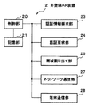
図3は、本発明による無線アクセスシステムの第二の実施の形態を示すブロック図である。
図4は、第二の実施の形態の登録AP装置の一例を示す構成図である。
図5は、第二の実施の形態の非登録AP装置の一例を示す構成図である。
図6は、第二の実施の形態の認証サーバの一例を示す構成図である。
図7は、第二の実施の形態の無線アクセスシステムの動作の一例を示すフロー図である。
図8は、本発明による無線アクセスシステムの第三の実施の形態を示すブロック図である。
図9は、第三の実施の形態の登録AP装置の一例を示す構成図である。
図10は、第三の実施の形態の非登録AP装置の一例を示す構成図である。
図11は、第三の実施の形態の認証サーバの一例を示す構成図である。
図12は、第三の実施の形態の無線アクセスシステムの動作の一例を示すフロー図である。
図13は、本発明による無線アクセスシステムの第四の実施の形態を示すブロック図である。
図14は、第四の実施の形態の登録AP装置の一例を示す構成図である。
図15は、第四の実施の形態の非登録AP装置の一例を示す構成図である。
図16は、第四の実施の形態の認証サーバの一例を示す構成図である。
図17は、第四の実施の形態の認証サーバが備える契約ユーザテーブルの一例を示す図である。
図18は、第四の実施の形態の認証サーバが備える任意設定テーブルの一例を示す図である。
図19は、第四の実施の形態の認証サーバが備える利用履歴テーブルの一例を示す図である。
図20は、第四の実施の形態の無線アクセスシステムの登録AP装置設置時の動作の一例を示すフロー図である。
図21は、第四の実施の形態の無線アクセスシステムの非登録AP装置設置時の動作の一例を示すフロー図である。
図22は、第四の実施の形態の無線アクセスシステムの運用時の動作の一例を示すフロー図である。FIG. 1 is a block diagram showing a first embodiment of a radio access system according to the present invention.
FIG. 2 is an operation flowchart of the second access point device according to the first embodiment.
FIG. 3 is a block diagram showing a second embodiment of the radio access system according to the present invention.
FIG. 4 is a configuration diagram illustrating an example of a registered AP device according to the second embodiment.
FIG. 5 is a configuration diagram illustrating an example of an unregistered AP apparatus according to the second embodiment.
FIG. 6 is a configuration diagram illustrating an example of the authentication server according to the second embodiment.
FIG. 7 is a flowchart illustrating an example of the operation of the wireless access system according to the second embodiment.
FIG. 8 is a block diagram showing a third embodiment of the radio access system according to the present invention.
FIG. 9 is a configuration diagram illustrating an example of a registered AP device according to the third embodiment.
FIG. 10 is a configuration diagram illustrating an example of an unregistered AP apparatus according to the third embodiment.
FIG. 11 is a configuration diagram illustrating an example of an authentication server according to the third embodiment.
FIG. 12 is a flowchart illustrating an example of the operation of the wireless access system according to the third embodiment.
FIG. 13 is a block diagram showing a fourth embodiment of the radio access system according to the present invention.
FIG. 14 is a configuration diagram illustrating an example of a registered AP device according to the fourth embodiment.
FIG. 15 is a configuration diagram illustrating an example of an unregistered AP apparatus according to the fourth embodiment.
FIG. 16 is a configuration diagram illustrating an example of an authentication server according to the fourth embodiment.
FIG. 17 is a diagram illustrating an example of a contract user table included in the authentication server according to the fourth embodiment.
FIG. 18 is a diagram illustrating an example of an arbitrary setting table provided in the authentication server according to the fourth embodiment.
FIG. 19 is a diagram illustrating an example of a usage history table provided in the authentication server according to the fourth embodiment.
FIG. 20 is a flowchart illustrating an example of the operation when the registered AP device is installed in the wireless access system according to the fourth embodiment.
FIG. 21 is a flowchart illustrating an example of an operation when the unregistered AP device is installed in the wireless access system according to the fourth embodiment.
FIG. 22 is a flowchart illustrating an example of an operation during operation of the wireless access system according to the fourth embodiment.
次に、本発明の実施の形態について図面を参照して詳細に説明する。
〔第一の実施の形態〕
図1は、本発明による無線アクセスシステムの第一の実施の形態を示す構成図である。
図1を参照すると、本実施の形態の無線アクセスシステムは、第一のアクセスポイント装置1Aと、第二のアクセスポイント装置2Aと、端末3Aと、ネットワーク4Aと、認証サーバ5Aとを有する。
第一のアクセスポイント装置1Aは、予め自身の認証情報が認証サーバ5Aに登録されたアクセスポイント装置である。
第二のアクセスポイント装置2Aは、第一のアクセスポイント装置1A、端末3Aとインターフェースを有し、さらに、ネットワーク4Aを介して認証サーバ5Aともインターフェースを有する。
端末3Aは、携帯電話機や、PDA(Personal Data Assistant)などの無線携帯端末である。また、ネットワーク4Aは、インターネット、及びATM(Asynchronous Transfer Mode)方式等による通信事業者のバックボーンネットワークを含む。さらに、認証サーバ5Aは、アクセスポイント装置を認証する装置である。
ここで、第二のアクセスポイント装置2Aは、認証情報取得部11A、記憶部12A、送信部13Aを有する。
第二のアクセスポイント装置2Aの認証情報取得部11Aは、第一のアクセスポイント装置1Aから自身を認証するための認証情報を取得する。尚、認証情報取得部11Aは、たとえば、予め第一のアクセスポイント装置1Aのアドレス(例えばIPアドレス)を、第二のアクセスポイント装置2Aの操作ボタン(図示せず)を操作することによって入力し、記憶するものとする。
第一のアクセスポイント装置1Aからの認証情報は、ネットワーク4Aを経由して取得しても良いし、あるいは、第一のアクセスポイント装置1Aから無線で直接取得するようにしても良く、この実施の形態では、その方法を限定しない。また、認証情報を取得する契機は、第二のアクセスポイント装置2Aの操作ボタン(図示せず)を操作することで発生するコマンドによっても良いし、あるいは、ネットワーク接続時に自動で取得するような仕組みによっても良い。
記憶部12Aは、取得された認証情報を一時的に保存する装置であり、たとえば、電源を落としても消失しないSRAM(Static Randam Access Memory)、あるいは電源を落とすと消失するRAMで構成され、必要に応じて選択される。
送信部13Aは、端末3Aから「接続要求」信号を受信したとき、記憶部12Aに記憶した認証情報を、ネットワーク4Aを介して認証サーバ5Aに送信する。この送信は、自身の記憶部12Aに記憶した認証情報を、通信事業者の認証機関である認証サーバで認証してもらうために行われる。
尚、本実施の形態では、送信部13Aが、端末3Aから「接続要求」信号を受信するようにしているが、全体を制御する制御部(図示せず)が端末から「接続要求」信号を検出し、制御部がそれを契機として送信部13Aを起動するようにしても良い。
図2は、第二のアクセスポイント装置2Aの動作フロー図である。第二のアクセスポイント装置2Aは、次のように動作する。
(1)認証情報取得部11Aは、予め記憶している相手アドレスに基づき、第一のアクセスポイント装置1Aにアクセスし、第一のアクセスポイント装置1Aから認証情報を取得し、取得した認証情報を記憶部12Aに記憶する(ステップA1)。
(2)送信部13Aは、端末3Aから、「接続要求」信号を受信する(ステップA2)。
(3)送信部13Aは、「接続要求」を受信すると、記憶部12Aに記憶した認証情報を、ネットワーク4Aを介して認証サーバ5Aに送信する(ステップA3)。
上述のステップA3の後、認証サーバ5Aは、第二のアクセスポイント装置2Aからネットワーク4Aを介して受信した認証情報と、あらかじめ記憶された第一のアクセスポイント装置1Aの認証情報とに基づいて、第二のアクセスポイント装置2Aに対する認証処理を実行する。具体的には、両者の認証情報を照合し一致すれば、認証OKの認証結果情報を出力する。
そして、認証結果情報は、認証サーバ5Aからネットワーク4Aを経由して第二のアクセスポイント装置2Aに送信される。第二のアクセスポイント装置2Aは、認証OKの場合、端末3Aに対する帯域を確保する。
以上説明したように、第一の実施の形態の無線アクセスシステムは、認証情報を記憶する第一のアクセスポイント装置1Aと、第二のアクセスポイント装置2Aと、認証サーバ5Aとを含む。そして、第二のアクセスポイント装置2Aは、第一のアクセスポイント装置1Aから認証情報を取得して記憶し、端末3Aからの接続要求により、認証情報をネットワーク4Aに送信する。さらに、認証サーバ5Aは、第二のアクセスポイント装置2Aからネットワーク4Aを介して受信した認証情報と、あらかじめ記憶された第一のアクセスポイント装置1Aの認証情報とに基づいて、第二のアクセスポイント装置2Aに対する認証処理を実行する。
このように、認証情報が認証サーバに登録されたアクセスポイント装置(第一のアクセスポイント装置1A)を1つ用意すれば、その他のアクセスポイント装置(第二のアクセスポイント装置2A)は、その登録されたアクセスポイント装置から認証情報を取得するため、ユーザが認証データの登録作業を行なう必要がない。また、本実施の形態では、認証時に、既に登録されている第一のアクセスポイント装置の認証情報を用いるため、認証サーバに新たに第二の認証情報を登録する必要がない。そのため、個人が複数の場所にフェムトセルのアクセスポイント装置(第二のアクセスポイント装置2A)を設置する場合、ユーザによる設置の際の作業効率が良いという効果がある。
また、本実施の形態の第二のアクセスポイント装置2Aは、上述の説明から分かるように、フェムトセルのアクセスポイント装置として装置構成を汎用化することができるという効果がある。
なぜなら、本実施の形態のアクセスポイント装置は、個人が他の場所に設置したアクセスポイント装置の認証情報を取得することができる構成を備えるので、設置時の初期状態で自身の認証情報を保有しておく必要がないからである。
〔第二の実施の形態〕
次に、本発明による無線アクセスシステムの第二の実施の形態について説明する。図3は、本発明による無線アクセスシステムの第二の実施の形態を示す構成図である。
図3を参照すると、本実施の形態は、登録AP装置1、非登録AP装置2、携帯端末3、携帯端末4、ネットワーク5、認証サーバ6、相手端末7を有する。
尚、APはアクセスポイント(Access Point)の略称である。
また、図4、図5、図6は、それぞれ登録AP装置1、非登録AP装置2、及び認証サーバ6の一例を示すブロック図である。ここで、図1に示す第一の実施の形態との対応関係において、登録AP装置1は、第一のアクセスポイント装置1Aに、非登録AP装置2は、第二のアクセスポイント装置2Aに、認証サーバ6は、認証サーバ5Aにそれぞれ対応する。
登録AP装置1は、その認証情報が予め認証サーバ6に登録されたアクセスポイント装置である。
登録AP装置1は、図4に示すように、制御部10、記憶部11、認証情報送信部12、ネットワーク通信部14、端末通信部15を有する。
制御部10は、登録AP装置1の動作を制御する。即ち、制御部10は、後述するネットワーク通信部14や、端末通信部15を介して外部から受信した受信データ、あるいは図示しない装置のコマンド入力部からの入力データを解析し、必要な処理を行う。制御部10は、例えば、データ解析の結果、データ転送要求を認識すれば、ネットワーク通信部14と端末通信部15間のデータ転送処理を行う。また、制御部10は、データ解析の結果、記憶部11への保存要求を認識すれば、記憶部11へのデータ記憶処理を行い、記憶部11からの読み出し要求を認識すれば、記憶部11からのデータ読み出し処理を行う。あるいは、制御部10は、データ解析の結果、予め用意されている機能部(例えば、認証情報送信部12)の実行の必要性を認識すれば、対応する機能部を起動して、機能部に機能を実行させる。
記憶部11は、自身の認証データ、即ち、ライセンス情報111及び使用する帯域情報112を格納する「第二の記憶部」に対応する。
認証情報送信部12は、非登録AP装置2からの認証情報要求受信時、制御部10から起動され、記憶部11に記憶された認証情報即ち、ライセンス情報111及び帯域情報112を、非登録AP装置2に送信する。ライセンス情報は、登録AP装置1が通信事業者と契約されていることを示す証明書である。また、帯域情報も、登録AP装置1を通信事業者と契約した時に、通信事業者から割り当てられる周波数帯域である。
ネットワーク通信部14は、ネットワークとの間でデータの送受信を行う。端末通信部15は、携帯端末3との間で無線データの送受信を行う。
非登録AP装置2は、その認証情報が認証サーバ6に登録されていないアクセスポイント装置である。
非登録AP装置2は、図5に示すように、制御部20、記憶部21、認証情報要求部23、認証要求部24、帯域割当部25、ネットワーク通信部27、端末通信部28を有する。
制御部20は、登録AP装置1における制御部10と同様に、非登録AP装置2全体の動作を制御する。記憶部21は、登録AP装置1の認証データ、即ち、ライセンス情報及び帯域情報を格納する「第一の記憶部」に対応する。
認証情報要求部23は、ネットワーク5を介して、登録AP装置1に対し、登録AP装置1の認証情報の取得要求を行い、取得した登録AP装置1の認証情報を記憶部21に格納する。尚、認証情報要求部23は、予め登録AP装置1のアドレス(例えばIPアドレス)を非登録AP装置2の操作ボタン(図示せず)を操作することによって与えられ、認証情報要求部23内に記憶しているものとする。
この取得要求は、第一の実施の形態と同様に、非登録AP装置2がネットワークに接続されたときに行っても良いし、ネットワーク接続後に非登録AP装置2の操作ボタン(図示せず)を操作することによって与えられるコマンド等によって行っても良い。
認証要求部24は、携帯端末4からの接続要求があると、制御部20から起動され、認証サーバ6との間にセッションを張り、記憶部21に保存されているライセンス情報及び帯域情報を認証情報として認証サーバ6に送信する。
帯域割当部25は、認証サーバ6から利用許可通知信号を受信すると、携帯端末4に対し、記憶部21に記憶された帯域を割当る。
ネットワーク通信部27は、ネットワークとの間でデータの送受信を行う。端末通信部28は、携帯端末4との間で無線データの送受信を行う。
再び図3において、携帯端末3、携帯端末4は、携帯電話機や、PDAなどの無線携帯端末である。ネットワーク5は、インターネット、及びATM(Asynchronous Transfer Mode)方式等による通信事業者のバックボーンネットワークを含む。相手端末7は、携帯端末4が通話する相手の携帯端末である。
次に、認証サーバ6は、アクセスポイント装置を認証する機能を有し、図6に示すように、制御部60、記憶部61、AP登録部62、AP認証部63、ネットワーク通信部66を有する。
制御部60は、認証サーバ6全体の動作を制御する。AP登録部62は、登録AP装置1の認証情報、即ち、ライセンス情報と、登録AP装置1の携帯端末3へ開放できる帯域情報とを記憶部61に登録する。AP認証部63は、非登録AP装置2から送られてくる認証情報即ち、ライセンス情報及び帯域情報と、記憶部61に格納された認証情報を照合し、一致すれば認証OKとする。認証時に照合する情報は、記憶部61の登録AP装置1のライセンス情報611、及び、帯域情報612である。
利用許可通知部64は、非登録AP装置2の認証がOKの時に、非登録AP装置2によって張られたセッションを介し、携帯端末4に対する帯域割当を許可するための利用許可通知情報を、非登録AP装置2に送信する。ネットワーク通信部66は、ネットワークとの間でデータの送受信を行う。
尚、認証サーバは、携帯電話事業者網の交換機であってもよいし、交換機と接続された別の機器であっても良い。
次に、図7を参照し、本第二の実施の形態の無線アクセスシステムの動作の一例を説明する。
尚、予め、認証サーバ6の記憶部61には、AP登録部62により、通信事業者と契約した登録AP装置1のライセンス情報611、及び、帯域情報612が登録されているものとする。
(1):非登録AP装置2の認証情報要求部23は、登録AP装置1の認証情報の取得要求を発生し、ネットワーク通信部27を介して、予め記憶している相手アドレスに基づき、登録AP装置1に対してこの認証情報の取得要求を送信する(ステップS1)。
(2):登録AP装置1の認証情報送信部12は、非登録AP装置2から認証情報の取得要求を受信すると記憶部11に記憶された認証情報即ち、ライセンス情報及び帯域情報を非登録AP装置2に送信する。非登録AP装置2は、取得した登録AP装置1の認証情報を記憶部21に格納する。(ステップS2)。
(3):携帯端末4は、非登録AP装置2に接続要求を送信する(ステップS3)。
(4):接続要求を端末通信部28で受信すると、非登録AP装置2の認証要求部24は、認証サーバ6に対し、ネットワーク通信部27を介して登録AP装置1より取得したライセンス情報及び帯域情報を、認証要求情報として認証サーバ6に送信する(ステップS4)。
(5):認証サーバ6のAP認証部63は、受信した認証要求情報の中の認証情報(ライセンス情報及び帯域情報)を記憶部61の認証情報と照合し、一致を確認する(ステップS5)。
(6):一致確認後、認証サーバ6の利用許可通知部64は、非登録AP装置2に対し利用許可通知情報を送信する(ステップS6)。
(7):非登録AP装置2の帯域割当部25は、利用許可通知情報を受信すると、携帯端末4に対し帯域を割り当てる(ステップS7)。この帯域は、記憶部21に記憶した帯域情報における帯域の中から決定される。
(8):携帯端末4は、通知された帯域を使用して、相手端末7との間にセッションを形成し、通話状態となる(ステップS8)。
本第二の実施の形態は、上述の説明から分かるように、個人が複数の場所にフェムトセルのアクセスポイント装置を設置する場合、ユーザによる設置のための作業効率が良いという効果がある。
なぜなら、ユーザが新規に設置するアクセスポイント装置の認証情報を、その都度、新たに認証サーバに登録する作業を必要としないからである。それは、新規に設置するアクセスポイント装置が、認証情報が認証サーバに既に登録されているアクセスポイント装置の認証情報を取得し、その認証情報を用いて認証サーバにアクセスする構成を備えるからである。
つまり、本実施の形態では、第二のアクセスポイント装置に対応する非登録AP装置2は、第一のアクセスポイント装置に対応する登録AP装置1に認証情報の取得要求を送信する認証情報要求部23と、取得要求により取得された認証情報を記憶する第一の記憶部(記憶部21)とを含む。さらに、非登録AP装置2は、端末から接続要求があると、第一の記憶部(記憶部21)に記憶された認証情報を、ネットワーク5を介して認証サーバ6に送信する送信部(認証要求部24、ネットワーク通信部27)を含む。
したがって、非登録AP装置2をネットワーク5に接続したときに、1つのボタン操作のみで、登録AP装置1に対して認証情報の取得を要求することで、ユーザの手間をほとんどかけずに、認証情報を取得することができる。
また、非登録AP装置2は、認証が必要な時には、登録AP装置1の認証情報により認証サーバに対して認証要求をすることができるので、認証サーバ6での認証が容易に得られる利点がある。
〔第三の実施の形態〕
次に、本発明による無線アクセスシステムの第三の実施の形態について説明する。
図8は、本発明の第三の実施の形態を示す構成図である。
図8を参照すると、本実施の形態は、登録AP装置1−1、非登録AP装置2−1、携帯端末3、携帯端末4、IPネットワーク51、通信事業者ネットワーク52、認証サーバ6−1、相手端末7から構成される。
また、図9、図10、図11は、それぞれ登録AP装置1−1、非登録AP装置2−1、及び認証サーバ6−1の一例を示すブロック図である。
尚、図8〜図11においては、第二の実施の形態における機能ブロックと同一の機能ブロックには、同一の参照番号を付与している。
ここで、図1に示す第一の実施の形態との対応関係において、登録AP装置1−1は、第一のアクセスポイント装置1Aに、非登録AP装置2−1は、第二のアクセスポイント装置2Aに、認証サーバ6−1は、認証サーバ5Aにそれぞれ対応する。
図9において、登録AP装置1−1は、その認証情報が予め認証サーバ6−1に登録されたアクセスポイント装置である。登録AP装置1−1は、制御部10、記憶部11−1、認証情報送信部12、通信履歴情報保存・送信部13、ネットワーク通信部14、端末通信部15を有する。
制御部10、認証情報送信部12、ネットワーク通信部14、端末通信部15は、第二の実施の形態における機能ブロックと同一であるため、説明を省略する。
記憶部11−1は、自身の認証データ、即ち、ライセンス情報111及び使用する帯域情報112のほかに、認証サーバへの接続情報であるサーバ接続情報113を格納する。この記憶部11−1は、「第二の記憶部」に対応する。尚、ライセンス情報は、登録AP装置1−1が通信事業者と契約されていることを示す証明書である。また、帯域情報も、登録AP装置1−1を通信事業者と契約した時に、通信事業者から割り当てられる周波数帯域である。
通信履歴情報保存・送信部13は、制御部10から起動され、携帯端末に割り当てた帯域、割り当て日時などの履歴情報を通信履歴情報として蓄積し、一定時間毎に認証サーバ6−1に報告する。
次に、非登録AP装置2−1は、その認証情報が認証サーバ6に登録されていないアクセスポイント装置であり、「第二のアクセスポイント装置」に対応する。図10に示すように、非登録AP装置2−1は、制御部20、記憶部21−1、ネットワーク接続部22、認証情報要求部23、認証要求部24−1、帯域割当部25、通信履歴情報発行部26、ネットワーク通信部27、端末通信部28を有する。
制御部20、認証情報要求部23、ネットワーク通信部27、端末通信部28は、第二の実施の形態における機能ブロックと同一であるため、説明を省略する。
記憶部21−1は、登録AP装置1−1から取得した登録AP装置1−1の認証データ、即ち、ライセンス情報及び帯域情報、及びサーバ接続情報を格納し、「第一の記憶部」に対応する。
ネットワーク接続部22は、非登録AP装置2−1をブロードバンドのインターネットに接続すると、周知のDHCP(Dynamic Host Configuration Protocol)を用いて、認証情報要求部23を起動する。即ち、本実施の形態では、非登録AP装置2−1をインターネットに接続すると、自動的に認証情報要求部23を起動する。尚、ブロードバンド回線には、FTTH(Fiber To The Home)やADSL(Asymmetric Digital Subscriber Line)等がある。
認証要求部24−1は、携帯端末4からの接続要求があると、記憶部21−1に記憶されたサーバ接続情報を用いて認証サーバ6−1との間にセッションを張り、該記憶部に保存されているライセンス情報及び帯域情報を認証サーバ6に送信する。
帯域割当部25は、認証サーバ6−1から利用許可通知情報を受信すると、携帯端末4に対し、記憶部21−1に記憶された帯域を割当る。
通信履歴情報発行部26は、携帯端末4の通話が終了すると、使用した帯域情報、即ち、帯域のバンド領域、使用時間などを通信履歴情報にして登録AP装置1−1に送信する。
再び図8において、携帯端末3、携帯端末4は、携帯電話機や、PDAなどの無線携帯端末である。相手端末7は、携帯端末4が通話する相手の携帯端末である。ネットワーク51は、インターネットである。通信事業者ネットワーク52は、携帯電話サービスを提供する通信事業者のネットワークであり、ATM(Asynchronous Transfer Mode)方式等によるバックボーンネットワークを含む。
認証サーバ6−1は、第二の実施の形態における認証サーバ6と同等の機能に加え、利用料金算出部65を備える。
図11において、利用料金算出部65は、登録AP装置1−1から定期的に送られてくる通信履歴情報に基づき、登録AP装置1−1の帯域の使用料金を算出する。
次に、図12を参照し、この無線アクセスシステムの動作の一例を説明する。
尚、予め、認証サーバ6−1の記憶部61には、AP登録部62により、通信事業者と契約した登録AP装置1−1のライセンス情報611、及び、帯域情報612が登録されているものとする。
(1):非登録AP装置2−1のネットワーク接続部22は、非登録AP装置2−1がIPネットワーク51に接続されると、認証情報要求部23を起動する(ステップS10)。
(2):非登録AP装置2−1の認証情報要求部23は、ネットワーク通信部27、IPネットワーク51を介して、予めIPアドレスを記憶している登録AP装置1−1にアクセスして、登録AP装置1−1の認証情報の取得要求を行う(ステップS11)。
(3):登録AP装置1−1の認証情報送信部12は、記憶部11−1に記憶された認証情報であるライセンス情報、帯域情報及びサーバ接続情報を非登録AP装置2−1に送信する。非登録AP装置2−1は、取得した登録AP装置1−1の認証情報及びサーバ接続情報を記憶部21−1に格納する。(ステップS12)。
(4):携帯端末4は、非登録AP装置2−1に接続要求を送信する(ステップS13)。
(5):接続要求を端末通信部28で受信すると、非登録AP装置2−1の認証要求部24は、登録AP装置1−1より取得したサーバ接続情報を用いて認証サーバ6−1と接続する。そして、登録AP装置1−1より取得したライセンス情報及び帯域情報を認証要求データとして、ネットワーク通信部27を介して認証サーバ6−1に送信する(ステップS14)。
(6):認証サーバ6−1のAP認証部63は、非登録AP装置2−1から送られて来た認証情報を記憶部61の認証情報と照合し、一致を確認する(ステップS15)。
(7):認証サーバ6−1の利用許可通知部64は、認証結果がOKの時、非登録AP装置2−1に対して利用許可通知情報を送信する(ステップS16)。
(8):非登録AP装置2−1の帯域割当部25は、利用許可通知情報を受信すると、携帯端末4に対して帯域を割り当てる(ステップS17)。
(9):携帯端末4は、通知された帯域を使用して、相手端末7との間にセッションを形成し、通話状態となる(ステップS18)。
(10):通話が終了すると、携帯端末4は、非登録AP装置2−1の端末通信部28に通話終了を通知する(ステップS19)。
(11):通話終了に基づき、非登録AP装置2−1の通信履歴情報発行部26は、使用帯域のバンド領域、使用時間などの履歴情報を通信履歴情報として登録AP装置1−1に送信する(ステップS20)。
(12):登録AP装置1−1の通信履歴情報保存・送信部13は、非登録AP装置2−1から受信した通信履歴情報を保存し、一定時間毎に認証サーバ6−1に送信する(ステップS21)。
(13):認証サーバ6−1の帯域利用料金算出部65は、登録AP装置1−1から送信された通信履歴情報に基づき帯域使用料金を計算する(ステップS22)。
上述の説明から分かるように、本第三の実施の形態は、任意の場所に個人のフェムトセルを設置することができる効果がある。なぜなら、アクセスポイント装置を任意の場所でインターネットに接続すると、認証情報が既に認証サーバに登録されているアクセスポイント装置の認証情報を、自動的に取得する機能を有するネットワーク接続部を備えたからである。
そして、さらに、本第三の実施の形態は、個人が複数の場所にフェムトセルのアクセスポイント装置を設置する場合、ユーザによる設置のための作業効率が良いという効果がある。
なぜなら、ユーザが新規にアクセスポイント装置を設置する毎に認証情報を新たに認証サーバに登録するとういう、ユーザの作業を必要としないからである。それは、新規に設置するアクセスポイント装置が、認証情報が認証サーバに既に登録されているアクセスポイント装置の認証情報を取得し、その取得した認証情報を用いて、認証時に、認証サーバにアクセスする構成を備えるからである。
さらに、本第三の実施の形態は、登録AP装置及び非登録AP装置を用いた通信履歴を容易に把握することができる効果がある。
なぜなら、非登録AP装置は、通信が終了するたびに使用帯域を通信履歴情報として登録AP装置に発行し、登録AP装置は通信履歴情報を蓄積して、一定時間毎に認証サーバに送信するようにしたからである。
〔第四の実施の形態〕
次に、本発明による無線アクセスシステムの第四の実施の形態について説明する。
第四の実施の形態は、任意の場所にAP装置を設置するに当たって、他のAP装置との電波干渉の有無を確認してから設置を許可する構成を含む点において、第一の実施の形態ないし第三の実施の形態と異なる。また、その相違に関連して、設置時に認証サーバと通信を行う点においても、第一の実施の形態ないし第三の実施の形態と異なる。
また、第三の実施の形態においては、通信利用履歴を非登録AP装置から登録AP装置に転送し、登録AP装置が定期的に認証サーバに送信する構成をとっていた。しかし、第四の実施の形態においては、携帯端末による通信が終了する度に、非登録AP装置及び登録AP装置のそれぞれが利用履歴を認証サーバに通知する形態となっている。これにより、第三の実施の形態よりもAP装置における処理負荷を軽減することができる。
図13は、本発明の第四の実施の形態を示す構成図である。
図13を参照すると、本実施の形態は、登録AP装置1−2、非登録AP装置2−2、携帯端末3、携帯端末4、IPネットワーク51、通信事業者ネットワーク52、認証サーバ6−2、相手端末7から構成される。
また、図14、図15、図16は、それぞれ登録AP装置1−2、非登録AP装置2−2、及び認証サーバ6−2の一例を示すブロック図である。
尚、図14〜図16においては、第三の実施の形態における機能ブロックと同一の機能ブロックには、同一の参照番号を付与している。
ここで、図1に示す第一の実施の形態との対応関係において、登録AP装置1−2は、第一のアクセスポイント装置1Aに、非登録AP装置2−2は、第二のアクセスポイント装置2Aに、認証サーバ6−2は、認証サーバ5Aにそれぞれ対応する。
図14において、登録AP装置1−2は、その認証情報が予め認証サーバ6−2に登録されたアクセスポイント装置である。
登録AP装置1−2は、制御部10−1、記憶部11−2、認証情報送信部12、ネットワーク通信部14−1、端末通信部15−1、認証要求部16、帯域割当部17、無線リソーススキャン部18を有する。
制御部10−1は、登録AP装置1−2の動作の全般を制御する。即ち、制御部10−1は、後述するネットワーク通信部14−1、端末通信部15−1や、無線リソーススキャン部16を介して外部から受信した受信データ、あるいは図示しない装置のコマンド入力部からの入力データを解析し、必要な処理を行う。制御部10−1は、例えば、データ解析の結果、データ転送要求を認識すれば、ネットワーク通信部14−1と端末通信部15−1間のデータ転送処理を行う。また、制御部10−1は、データ解析の結果、記憶部11−2への保存要求を認識すれば、記憶部11−2へのデータ記憶処理を行い、記憶部11−2からの読み出し要求を認識すれば、記憶部11−2からのデータ読み出し処理を行う。つまり、制御部10−1は、データ解析の結果、予め用意されている機能部の実行の必要性を認識すれば、対応する機能部を起動して、機能部に機能を実行させる。
記憶部11−2は、自身の認証データ、即ち、ライセンス情報111及び使用する帯域情報112のほかに、認証サーバへの接続情報であるサーバ接続情報113や当該AP装置を特定する情報である登録AP装置識別情報(ID)114および当該AP装置を設置する契約ユーザを識別する契約ユーザID115を格納する。この登録AP装置ID114は、当該AP装置を一意に識別することができる情報であり、例えば当該AP装置の製造番号やMAC(Media Accsess Control)アドレス等が対応する。契約ユーザID115は、後述するように、契約時に通信事業者から割り当てられる情報であり、本実施の形態においては、契約ユーザが保有する携帯端末の識別情報(端末ID)が割り当てられる。なお、この記憶部11−2は、「第二の記憶部」に対応する。また、ライセンス情報111は、登録AP装置1−2が通信事業者と契約されていることを示す証明書である。また、帯域情報112は、登録AP装置1−2を通信事業者と契約した時に、通信事業者から割り当てられる周波数帯域のうち、後述する電波状況スキャン結果にもとづいて他のAP装置との電波干渉がないと判定された、当該登録AP装置1−2で使用できる周波数帯域である。
認証要求部16は、制御部10−1から起動され、認証サーバ6−2との間にセッションを張り、記憶部11−2に保存されているライセンス情報等の認証情報を認証サーバ6−2に送信して認証登録する。また、運用中は、携帯端末からの接続要求受信時に、制御部10−1から起動され、認証サーバ6−2に対して個々の通信の認証要求を行なう。
帯域割当部17は、個々の通信の認証完了通知(利用許可通知)を認証サーバ6−2から受けると、認証サーバ6−2から登録完了通知とともに指示されて記憶部11−2に記憶している帯域を、携帯端末4に対して割当る。前述の如く、この帯域は他のAP装置との電波干渉がないと判定された周波数帯域である。
無線リソーススキャン部18は、当該AP装置を設置する場所における、他のAP装置から送信される電波の受信状況(受信電界強度)をスキャンする装置である。後述するように、当該AP装置を設置する際に、認証サーバ6−2の指示で、制御部10−1から起動され、指示された周波数帯域の電波の受信電界強度をスキャンしてその結果を認証サーバ6−2に報告する。つまり、周辺に設置されているその他AP装置で使用されている電波との干渉状況を確認するために備える装置である。
ネットワーク通信部14−1は、インターネットや通信事業者ネットワークを含むネットワークを介したデータの送受信を行う。端末通信部15−1は、携帯端末との間で無線データの送受信を行う。
次に、非登録AP装置2−2は、登録AP装置1−2の設置後に、任意の場所に別途設置するアクセスポイント装置であり、「第二のアクセスポイント装置」に対応する。
図15に示すように、非登録AP装置2−2は、制御部20−1、記憶部21−2、ネットワーク接続部22−1、認証情報要求部23、認証要求部24−2、帯域割当部25、ネットワーク通信部27−1、端末通信部28−1、及び無線リソーススキャン部29を有する。
制御部20−1は、登録AP装置1−2における制御部10−1と同様に、非登録AP装置2−2全体の動作を制御する。
記憶部21−2は、登録AP装置1−2から取得した登録AP装置1−2の認証データを格納する「第一の記憶部」に対応する。また、記憶部21−2は、当該AP装置を特定する情報である非登録AP装置識別情報(ID)211を格納する。この非登録AP装置ID211は、当該AP装置を一意に識別することができる情報であり、例えば当該AP装置の製造番号やMAC(Media Accsess Control)アドレス等が対応する。
ネットワーク接続部22−1は、非登録AP装置2−2をブロードバンドのインターネットに接続すると、周知のDHCP(Dynamic Host Configuration Protocol)を用いて、認証情報要求部23を起動する。即ち、本実施の形態では、非登録AP装置2−2をインターネットに接続すると、自動的に認証情報要求部23を起動する。尚、ブロードバンド回線には、FTTH(Fiber To The Home)やADSL(Asymmetric Digital Subscriber Line)等がある。
認証情報要求部23は、インターネットを介して、登録AP装置1−2に対して、登録AP装置1−2の認証情報の取得要求を行い、取得した登録AP装置1−2の認証情報及びサーバ接続情報を記憶部21−2に格納する。尚、認証情報要求部23は、予め登録AP装置1−2のアドレス(例えばIPアドレス)を非登録AP装置2−2の操作ボタン(図示せず)を操作することによって与えられ、認証情報要求部23内に記憶しているものとする。
認証要求部24−2は、後述するように、当該AP装置を任意の場所に設置する際の動作において、制御部20−1から起動され、認証サーバ6−2との間にセッションを張り、記憶部21−2に保存されているライセンス情報等の認証情報及び非登録AP装置ID211を認証サーバ6−2に送信して認証登録する。また、運用中は、携帯端末からの接続要求受信時に、制御部20−1から起動され、認証サーバ6−2に対して個々の通信の認証要求を行なう。
帯域割当部25は、個々の通信の認証完了通知(利用許可通知)を認証サーバ6−2から受けると、認証サーバ6−2から登録完了通知とともに指示されて記憶部21−2に記憶している帯域を、携帯端末4に対して割当る。この記憶部21−2に記憶している帯域は、登録AP装置1−2の記憶部11−2が記憶している帯域と同様に、当該非登録AP装置2−2の設置場所において他のAP装置との電波干渉がないと判定された周波数帯域である。
ネットワーク通信部27−1は、インターネットや通信事業者ネットワークを含むネットワークを介したデータの送受信を行う。端末通信部28−1は、携帯端末との間で無線データの送受信を行う。
無線リソーススキャン部29は、登録AP装置1−2の無線リソーススキャン部16と同様に、当該AP装置を設置する場所における電波の干渉状況を測定する装置である。後述するように、当該AP装置を設置する際に、認証サーバ6−2の指示で、制御部10−2から起動され、指示された周波数帯域の電波の受信電界強度をスキャンして、周辺に設置されているその他AP装置で使用されている電波との干渉状況を認証サーバ6−2に報告する。
再び図13において、携帯端末3、携帯端末4は、携帯電話機や、PDAなどの無線携帯端末である。相手端末7は、携帯端末4が通話する相手の携帯端末である。ネットワーク51は、インターネットである。通信事業者ネットワーク52は、携帯電話サービスを提供する通信事業者のネットワークであり、ATM(Asynchronous Transfer Mode)方式等によるバックボーンネットワークを含む。
認証サーバ6−2は、第三の実施の形態における認証サーバ6−1と類似の機能に加え、第四の実施形態に特有の後述する各種管理テーブルを備える。
図16において、認証サーバ6−2は、制御部60−1、記憶部61−1、AP登録部62−1、AP認証部63−1、利用許可通知部64−1、利用履歴管理部65−1、及びネットワーク通信部66−1を有する。
制御部60−1は、認証サーバ6−2の全体の動作を制御する。AP登録部62−1は、登録AP装置1−2や非登録AP装置2−2の登録処理を行い、必要情報を記憶部61−2に記憶する。
記憶部61−2は、後述する契約ユーザテーブル621、任意設置テーブル622及び利用履歴テーブル623を記憶する。
AP認証部63−1は、記憶部61−2に記憶している情報にもとづいて登録AP装置1−2や非登録AP装置2−2の認証処理を行う。
利用許可通知部64−1は、登録AP装置1−2又は非登録AP装置2−2を介した携帯端末4からの接続要求の認証がOKの時に、登録AP装置1−2又は非登録AP装置2に携帯端末4に対する利用許可通知を送信する。
利用履歴管理部65−1は、登録AP装置1−2又は非登録AP装置2−2を介した携帯端末4の通信履歴を、記憶部61−2の利用履歴テーブル623に蓄積・管理する。
記憶部61−2が記憶する契約ユーザテーブル621、任意設置テーブル622及び利用履歴テーブル623の一例を図17ないし図19に示す。
図17は、認証サーバ6−2が備える契約ユーザテーブル621の一例を示す図である。
契約ユーザテーブル621は、登録AP装置1−2を設置する際に、その登録AP装置1−2に関わる各種情報を設定しておくテーブルである。この契約ユーザテーブル621は、ユーザとの契約時に定めた情報にもとづいて、後述する最初の設置認証動作(認証登録)を行なったときに設定される。
設定される情報は、契約ユーザを特定することができる識別情報としての契約ユーザID、認証に必要なライセンス情報、設置するAP装置を特定するための登録AP装置ID、契約時に割り当てた帯域情報のうちで、当該登録AP装置で使用可能な帯域情報を含む。
契約ユーザIDは、契約ユーザを一意に識別することができる情報であり、契約時に通信事業者から割り当てられる情報である。通常は、契約ユーザが保有する携帯端末の識別情報(端末ID)が割り当てられ、契約ユーザに通知される。登録AP装置IDは、当該AP装置を一意に識別することができる情報であり、前述の如く当該AP装置の製造番号やMAC(Media Accsess Control)アドレス等が対応する。また、帯域情報は、後述するように、周辺に設置された他のAP装置で使用されている電波状況を確認したうえで設定される、当該登録AP装置で使用可能な帯域情報である。従って、必ずしも契約時に割り当てたすべての帯域情報ではない。
図18は、認証サーバ6−2が備える任意設定テーブル622の一例を示す図である。
任意設定テーブル622は、登録AP装置1−2を設置した後で、非登録AP装置2−2を任意の場所に設置する際に、その非登録AP装置2−2に関わる各種情報を設定しておくテーブルである。この任意設定テーブル622は、後述するように、非登録AP装置2−2を設置する際の設置認証動作(任意登録)の時に設定される。
設定される情報は、設置する非登録AP装置を特定するための非登録AP装置ID、ライセンス情報を流用する登録AP装置を設置した契約ユーザの契約ユーザID、認証に必要なライセンス情報(登録AP装置から流用したライセンス情報)、当該非登録AP装置で使用可能な帯域情報を含む。
非登録AP装置IDは、当該AP装置を一意に識別することができる情報であり、前述の如く当該AP装置の製造番号やMAC(Media Accsess Control)アドレス等が対応する。契約ユーザIDおよび帯域情報は、前述のとおりである。
図19は、認証サーバ6−2が備える利用履歴テーブル623の一例を示す図である。利用履歴テーブル623は、登録AP装置および非登録AP装置が携帯端末により通信に使用された履歴を蓄積しておくテーブルである。
設定される情報は、接続要求により通信を行った携帯端末の利用者を特定するための識別情報である利用者ID、その携帯端末が通信に利用したAP装置のAP装置ID(登録AP装置IDおよび非登録AP装置IDのいずれかの装置ID)、そのAP装置を設置した契約ユーザを特定するための識別情報である契約ユーザID、そして、その通信の開始時刻と終了時刻である通信時間情報を含む。
利用者IDは、利用者が使用した携帯端末の識別情報(端末ID)であり、契約ユーザが利用者である場合には、契約ユーザIDと同じ情報となる。
次に、図20ないし図22を参照し、第四の実施の形態の無線アクセスシステムの動作の一例を説明する。
まず、図20を参照して、登録AP装置設置時の動作を説明する。図20は、第四の実施の形態の無線アクセスシステムの登録AP装置設置時の動作の一例を示すフロー図である。
登録AP装置1−2をネットワークに接続する前段階の処置として、契約ユーザは、通信事業者と契約した際に通知されたライセンス情報および契約ユーザIDを当該AP装置に登録する。契約ユーザIDは、契約時に通信事業者に申告した契約ユーザが保有する携帯端末の識別情報(端末ID)が割り当てられる。登録操作は、登録AP装置1−2の図示しない外部インターフェースにPC(Personal Computer、パーソナルコンピュータ)を接続し、AP装置登録アプリケーションプログラムを用いて必要情報の入力および登録を行なう。また、登録AP装置1−2に設けられた、図示しない入力操作ボタンを用いて必要情報を入力し、登録する方法でもよい。登録した情報は、登録AP装置1−2の記憶部11−2に記憶される。
このような前処理を行なった登録AP装置1−2をネットワークに接続すると、図20に示す認証登録動作が認証サーバ6−2との間で行われる。
(1):登録AP装置1−2の制御部10−1は、前処理を行なった登録AP装置1−2がネットワークに接続したことを検出すると、認証要求部16を起動する。認証要求部16は、サーバ接続情報にもとづいて認証サーバ6−2との間にセッションを張り、登録要求メッセージを送信する(ステップS100)。登録要求メッセージは、ライセンス情報、登録AP装置IDおよび契約ユーザIDを含む。
(2):認証サーバ6−2のAP認証部63−1は、登録AP装置1−2から受信した登録要求メッセージに含まれるライセンス情報、登録AP装置IDおよび契約ユーザIDを、図示しない契約情報データベースに登録されている契約時の情報と照合を行なう。該当する契約であることをAP認証部63−1が認証すると、認証サーバ6−2のAP登録部62−1は、契約ユーザテーブル621の設定を行なう(ステップS101)。つまり、契約ユーザテーブル621に、認証されたライセンス情報、登録AP装置IDおよび契約ユーザIDを設定する。
(3):次に、当該AP装置で使用可能な帯域情報を識別するために、AP登録部62−1は、契約時に割り当てたすべての帯域情報を登録AP装置1−2に通知して、それらの帯域の電波状況をスキャンして報告することを要求する、電波状況スキャン要求メッセージを送信する(ステップS102)。
(4):登録AP装置1−2の制御部10−1は、電波状況スキャン要求メッセージを受信すると、無線リソーススキャン部18を起動して、通知された帯域における周辺の電波の受信電界強度を測定するように指示する。無線リソーススキャン部18によるスキャン結果(受信電界強度の測定結果)は認証サーバ6−2に報告される(ステップS103)。
(5):認証サーバ6−2は、登録AP装置1−2から報告された、当該AP装置の周辺における電波状況を判断し、他のAP装置と干渉しない、この登録AP装置1−2で使用可能な帯域情報を識別する。この識別は、例えば、制御部60−1において、予め定めた受信電界強度の閾値を超えない帯域を、使用可能な帯域として識別すればよい。識別した使用可能な帯域情報は、契約ユーザテーブル621に設定される(ステップS104)。
(6):契約ユーザテーブル621に必要情報が設定されると、認証サーバ6−2のAP登録部62−1は、登録完了通知メッセージを登録AP装置1−2に送信する(ステップ105)。このとき、登録完了通知メッセージは、当該AP装置で使用可能な帯域情報を含む。
(7):認証サーバ6−2から登録完了通知メッセージを受信すると、登録AP装置1−2の制御部10−1は、登録完了通知メッセージに含まれる使用可能帯域情報を記憶部11−2に設定する(ステップ106)。
(8):以上の動作の後、ネットワークに接続された登録AP装置1−2は、運用状態に入る(ステップ107)。
以上に説明したように、第四の実施の形態の無線アクセスシステムの登録AP装置1−2は、当該AP装置をIPネットワークに設置した時に行なわれる、認証サーバ6−2による認証登録時に、認証サーバ6−2において契約ユーザテーブルが設定される。そのとき、設置場所周辺の電波状況を考慮して登録AP装置1−2で使用可能な帯域を設定する。
以上のようにして登録AP装置1−2をネットワークに接続して運用状態にした後、他の場所に非登録AP装置2−2を設置する動作を、図21を参照して説明する。
図21は、第四の実施の形態の無線アクセスシステムの非登録AP装置設置時の動作の一例を示すフロー図である。
前述したように、非登録AP装置2−1は、予め登録AP装置1−2のアドレス(例えばIPアドレス)を非登録AP装置2−2の操作ボタン(図示せず)を操作することによって与えられ、認証情報要求部23内に記憶している。
(1):非登録AP装置2−2のネットワーク接続部22−1は、非登録AP装置2−2がIPネットワーク51に接続されると、認証情報要求部23を起動する(ステップS200)。
(2):非登録AP装置2−2の認証情報要求部23は、ネットワーク通信部27−1、IPネットワーク51を介して、予めIPアドレスを記憶している登録AP装置1−2にアクセスして、登録AP装置1−2の認証情報の取得要求を行う(ステップS201)。
(3):登録AP装置1−2の認証情報送信部12は、記憶部11−2に記憶された認証情報及びサーバ接続情報を非登録AP装置2−2に送信する(ステップS202)。このとき送信される認証情報は、ライセンス情報、登録AP装置ID及び契約ユーザIDを含む。非登録AP装置2−2の制御部20−1は、取得した登録AP装置1−2の認証情報及びサーバ接続情報を記憶部21−2に格納する。
(4):登録AP装置1−2の認証情報及びサーバ接続情報の取得及び格納を確認した非登録AP装置2−2の制御部20−1は、次に、認証サーバ6−2に対して任意登録要求を行なう動作を開始する(ステップS203)。非登録AP装置2−2の制御部20−1は、認証要求部24−2を起動する。認証要求部24−2は、登録AP装置1−2から取得したサーバ接続情報にもとづいて認証サーバ6−2との間にセッションを張り、任意登録要求メッセージを送信する。任意登録要求メッセージは、登録AP装置1−2から取得したライセンス情報、登録AP装置IDおよび契約ユーザIDを含み、さらに当該非登録AP装置2−2の非登録AP装置IDを含む。
(5):認証サーバ6−2のAP認証部63−1は、非登録AP装置2−2から受信した任意登録要求メッセージにもとづいて、当該非登録AP装置2−2の認証(AP認証)を行なう(ステップS204)。このAP認証は、任意登録要求メッセージ含まれるライセンス情報、登録AP装置IDおよび契約ユーザIDを、契約ユーザテーブル621の登録情報と照合することにより実施する。つまり、任意登録要求メッセージ含まれるライセンス情報、登録AP装置IDおよび契約ユーザIDが、契約ユーザテーブル621に登録されているライセンス情報、登録AP装置IDおよび契約ユーザIDと一致する場合に、当該非登録AP装置を正当な非登録AP装置であると認証する。正当な非登録AP装置であることをAP認証部63−1が認証すると、認証サーバ6−2のAP登録部62−1は、任意設定テーブル622の設定を行なう。つまり、認証された非登録AP装置2−2の非登録AP装置IDを、対応する登録AP装置1−2のライセンス情報、登録AP装置IDおよび契約ユーザIDとともに、任意設定テーブル622に設定する。
(6):次に、当該AP装置で使用可能な帯域情報を識別するために、認証サーバ6−2のAP登録部62−1は、契約ユーザに契約時に割り当てたすべての帯域情報を非登録AP装置2−2に通知して、それらの帯域の電波状況をスキャンして報告することを要求する、電波状況スキャン要求メッセージを送信する(ステップS205)。
(7):非登録AP装置2−2の制御部20−1は、電波状況スキャン要求メッセージを受信すると、無線リソーススキャン部29を起動して、通知された帯域における周辺の電波の受信電界強度を測定するように指示する。無線リソーススキャン部29によるスキャン結果(受信電界強度の測定結果)は認証サーバ6−2に報告される(ステップS206)。
(8):認証サーバ6−2は、非登録AP装置2−2から報告された、当該AP装置の周辺における電波状況を判断し、この非登録AP装置2−2で使用可能な帯域情報を識別する。この識別は、例えば、制御部60−1において、予め定めた受信電界強度の閾値を超えない帯域を、使用可能な帯域として識別すればよい。識別した使用可能な帯域情報は、任意設定テーブル622に設定される(ステップS207)。
(9):任意設定テーブル622に必要情報が設定されると、認証サーバ6−2のAP登録部62−1は、登録完了通知メッセージを非登録AP装置2−2に送信する(ステップS208)。このとき、登録完了通知メッセージは、当該AP装置で使用可能な帯域情報を含む。
(10):認証サーバ6−2から登録完了通知メッセージを受信すると、非登録AP装置2−2の制御部20−1は、登録完了通知メッセージに含まれる使用可能帯域情報を記憶部21−2に設定する(ステップS209)。
(11):以上の動作の後、ネットワークに接続された非登録AP装置2−2は、運用状態に入る(ステップS210)。
以上に説明したように、第四の実施の形態の無線アクセスシステムの非登録AP装置2−2は、ネットワークに接続した設置時に、登録AP装置1−2から認証情報及びサーバ接続情報を取得する。続いて、登録AP装置1−2から取得した認証情報及びサーバ接続情報にもとづいて認証サーバ6−2に認証を求める。認証サーバ6−2では、契約ユーザテーブルの設定情報と認証要求情報との照合により、非登録AP装置2−2の認証を行なう。認証された非登録AP装置2−2に関する情報は、認証サーバ6−2において任意設定テーブルに設定される。そのとき、設置場所周辺の電波状況を考慮して非登録AP装置2−2で使用可能な帯域を設定する。
続いて、以上のようにネットワークに接続されて運用中の登録AP装置1−2及び非登録AP装置2−2を用いた、第四の実施の形態の無線アクセスシステムの運用時の動作を、図22を参照して説明する。
図22は、第四の実施の形態の無線アクセスシステムの運用時の動作の一例を示すフロー図である。
(1):携帯端末4は、登録AP装置1−2または非登録AP装置2−2を介した通信に際して、接続要求を送信する(ステップS301)。この接続要求には、利用者を識別する当該携帯端末の端末ID(利用者ID)を含む。
(2):接続要求を端末通信部28−1で受信した非登録AP装置2−2、又は端末通信部15−1で受信した登録AP装置1−2は、認証要求部24−2又は認証要求部16を起動する。認証要求部24−2/16は、サーバ接続情報を用いて認証サーバ6−2と接続して、当該接続要求に対する認証要求メッセージを送信する(ステップS302)。認証要求メッセージには、AP装置が記憶しているライセンス情報及びAP装置IDに加えて、携帯端末4の接続要求に含まれる携帯端末の端末ID(利用者ID)を認証要求データとして、ネットワーク通信部27−1/14−1を介して認証サーバ6−2に送信する。
(3):認証サーバ6−2のAP認証部63−1は、AP装置(非登録AP装置2−2、又は登録AP装置1−2)から送られて来た認証要求データを、契約ユーザテーブル621又は任意設定テーブル622と照合する。具体的には、AP装置IDにもとづいて、当該接続に使用しているAP装置を特定する。そして、契約ユーザテーブル621又は任意設定テーブル622にそのAP装置IDと対応して設定されているライセンス情報と、認証要求データに設定されているライセンス情報とを照合する。次に、AP認証部63−1は、認証された接続に対して利用履歴テーブル623を設定する(ステップS303)。具体的には、認証要求データに含まれる携帯端末の端末IDを利用者IDとして登録し、当該利用者IDに対応して接続に使用しているAP装置ID及び当該AP装置を設置した契約ユーザIDを設定する。契約ユーザIDは、契約ユーザテーブル621又は任意設定テーブル622から、特定したAP装置IDに対応する情報として求めることができる。また、通信開始時刻情報は、認証要求メッセージを送信したAP装置に対して利用許可通知メッセージを送信した時刻が記録される。つまり、認証結果がOKの場合、認証サーバ6−2の利用許可通知部64−1から、認証要求メッセージを送信したAP装置に対して、利用許可通知メッセージを送信する。
(4):AP装置(非登録AP装置2−2、又は登録AP装置1−2)の帯域割当部25/17は、利用許可通知情報を受信すると、当該AP装置で使用可能な帯域を携帯端末4に対して割り当てる。携帯端末4は、通知された帯域を使用して、相手端末7との間にセッションを形成し、通信を開始する(ステップS304)。
(5):通信が終了すると、携帯端末4は、接続に使用したAP装置(非登録AP装置2−2、又は登録AP装置1−2)の端末通信部28−1/15−1に通話終了を通知する(ステップS305)。
(6):通話終了に基づき、接続に使用したAP装置(非登録AP装置2−2、登録AP装置1−2)は、ネットワーク通信部27−1/14−1から通信終了報告メッセージを認証サーバ6−2に送信する(ステップS306)。通信終了報告メッセージには、AP装置ID及び携帯端末の端末ID(利用者ID)を含む。通信終了報告メッセージを受信した認証サーバ6−2は、利用履歴テーブルをAP装置ID及び利用者IDで検索し、該当する利用者IDに対応する通信終了時刻情報を登録する。
上述の説明から分かるように、第四の実施の形態は、個人が複数の場所にフェムトセルのアクセスポイント装置を設置する場合に、ユーザによる設置のための作業効率が良いという効果がある。
なぜなら、ユーザが新規にアクセスポイント装置を設置する毎に、認証情報を新たに認証サーバに登録するというユーザの作業を必要としないからである。それは、新規に設置するアクセスポイント装置が、認証情報が認証サーバに既に登録されているアクセスポイント装置の認証情報を取得し、その取得した認証情報を用いて、認証時に、認証サーバにアクセスする構成を備えるからである。
さらに、第四の実施の形態は、任意の場所に個人のフェムトセルを設置する場合において、周辺に設置されているフェムトセルとの電波干渉を防ぐことができる効果がある。
なぜなら、アクセスポイント装置を任意の場所に設置する際に、認証登録動作の一環として周辺の電波状況をスキャンしてから、使用する帯域情報を決定する構成を備えたからである。したがって、契約時に割り当てた帯域であっても、周辺の他のAP装置が使用している帯域は避けて使用することができ、電波干渉を防ぐことができる。
また、第四の実施の形態は、当該フェムトセルのサービスエリアにおける帯域使用状況を容易に把握することができる効果がある。なぜなら、各AP装置で使用可能な帯域情報は、契約ユーザテーブル及び任意設定テーブルに登録する構成を備えたからである。したがって、別途、各AP装置の設置場所の住所情報や、建造物の設置階情報を対応させることにより、使用帯域分布を知ることができる。
さらに、第四の実施の形態は、認証サーバが、接続の利用履歴を容易に把握することができる効果がある。
なぜなら、接続に使用するAP装置は、接続要求に伴う認証要求メッセージ及び通信が終了するたびに報告する通信終了報告メッセージに、AP装置ID及び携帯端末の端末ID(利用者ID)を含めて認証サーバに送信するようにしたからである。つまり、認証サーバには、利用履歴テーブルを備え、利用者IDと対応させて、接続に使用したAP装置ID、そのAP装置を設置した契約ユーザID、通信の開始時刻および終了時刻を記録するようにした。
そのため、契約ユーザが任意の場所に設置したAP装置を、その他のユーザが使用した場合の各種ビジネスモデルの構築が可能になる。例えば、契約ユーザが任意の場所に設置したAP装置を、その他のユーザが使用した場合には、その他のユーザから利用料金を徴収してその契約ユーザに対して利用料金を与える等インセンティブを付加することができる。また、契約ユーザが他の契約ユーザが設置したAP装置を使用した場合には、前述の利用料金を相殺するようにもできる。このようなビジネスモデルの構築により、個人が任意の場所にアクセスポイントを設置しようとする意欲が促進され、サービスエリアの拡大が計られる。
以上に第一ないし四の実施の形態を参照して本願発明を説明したが、本願発明は、上記の実施の形態に限定されるものではない。本願発明の構成や詳細には、本願発明のスコープの範囲で当業者が理解し得る様々な変更を行うことができる。
この出願は、2008年1月18日に出願された日本出願特願2008−008840を基礎とする優先権を主張し、その開示の全てをここに取り込む。Next, embodiments of the present invention will be described in detail with reference to the drawings.
[First embodiment]
FIG. 1 is a block diagram showing a first embodiment of a radio access system according to the present invention.
Referring to FIG. 1, the wireless access system of the present embodiment includes a first
The first
The second access point device 2A has an interface with the first
The terminal 3A is a mobile phone or a wireless mobile terminal such as a PDA (Personal Data Assistant). The
Here, the second access point device 2A includes an authentication
The authentication
The authentication information from the first
The
When the
In the present embodiment, the
FIG. 2 is an operation flowchart of the second access point device 2A. The second access point device 2A operates as follows.
(1) The authentication
(2) The
(3) Upon receiving the “connection request”, the
After the above step A3, the
Then, the authentication result information is transmitted from the
As described above, the wireless access system according to the first embodiment includes the first
In this way, if one access point device (first
Further, as can be seen from the above description, the second access point device 2A of the present embodiment has an effect that the device configuration can be generalized as an access point device of a femto cell.
This is because the access point device according to the present embodiment has a configuration in which an individual can acquire authentication information of an access point device installed in another place, and therefore has its own authentication information in an initial state at the time of installation. It is not necessary to keep it.
[Second Embodiment]
Next, a second embodiment of the wireless access system according to the present invention will be described. FIG. 3 is a block diagram showing a second embodiment of the wireless access system according to the present invention.
Referring to FIG. 3, the present embodiment includes a registered
AP is an abbreviation for an access point.
4, 5, and 6 are block diagrams illustrating examples of the registered
The registered
As illustrated in FIG. 4, the registered
The
The storage unit 11 corresponds to a “second storage unit” that stores its own authentication data, that is, the
The authentication
The
The
As illustrated in FIG. 5, the
The
The authentication
This acquisition request may be made when the
When there is a connection request from the
When receiving the use permission notification signal from the
The
In FIG. 3 again, the
Next, the
The
When the authentication of the
The authentication server may be a mobile phone carrier network switch or another device connected to the switch.
Next, an example of the operation of the wireless access system according to the second embodiment will be described with reference to FIG.
It is assumed that the
(1): The authentication
(2): When receiving the authentication information acquisition request from the
(3): The
(4): When the connection request is received by the
(5): The
(6): After confirming the match, the use
(7): When the
(8): The
As can be seen from the above description, the second embodiment has an effect that when an individual installs femtocell access point devices at a plurality of locations, the work efficiency for installation by the user is good.
This is because there is no need to newly register the authentication information of the access point device newly installed by the user in the authentication server each time. This is because a newly installed access point apparatus has a configuration in which authentication information of an access point apparatus whose authentication information is already registered in the authentication server is acquired and the authentication server is accessed using the authentication information.
That is, in the present embodiment, the
Accordingly, when the
In addition, the
[Third embodiment]
Next, a third embodiment of the wireless access system according to the present invention will be described.
FIG. 8 is a block diagram showing a third embodiment of the present invention.
Referring to FIG. 8, in the present embodiment, a registered AP device 1-1, a non-registered AP device 2-1, a
9, FIG. 10, and FIG. 11 are block diagrams illustrating examples of the registered AP device 1-1, the unregistered AP device 2-1, and the authentication server 6-1.
8 to 11, the same reference numerals are assigned to the same functional blocks as those in the second embodiment.
Here, in the correspondence with the first embodiment shown in FIG. 1, the registered AP device 1-1 is the first
In FIG. 9, a registered AP device 1-1 is an access point device whose authentication information is registered in advance in the authentication server 6-1. The registered AP apparatus 1-1 includes a
Since the
The storage unit 11-1 stores
The communication history information storage /
Next, the unregistered AP device 2-1 is an access point device whose authentication information is not registered in the
Since the
The storage unit 21-1 stores authentication data of the registered AP device 1-1 acquired from the registered AP device 1-1, that is, license information, bandwidth information, and server connection information, and stores them in the “first storage unit”. Correspond.
When the non-registered AP device 2-1 is connected to the broadband Internet, the
When there is a connection request from the
When the
When the call of the
In FIG. 8 again, the
The authentication server 6-1 includes a usage
In FIG. 11, the usage
Next, an example of the operation of this radio access system will be described with reference to FIG.
In addition, in the storage unit 61 of the authentication server 6-1, the
(1): When the unregistered AP device 2-1 is connected to the
(2): The authentication
(3): The authentication
(4): The
(5): When the
(6): The
(7): When the authentication result is OK, the usage
(8): When the
(9): The
(10): When the call ends, the
(11): Based on the end of the call, the communication history
(12): The communication history information storage /
(13): The bandwidth usage
As can be seen from the above description, the third embodiment has an effect that an individual femtocell can be installed at an arbitrary place. This is because the network connection unit has a function of automatically acquiring the authentication information of the access point device whose authentication information is already registered in the authentication server when the access point device is connected to the Internet at an arbitrary location. .
Further, the third embodiment has an effect that the work efficiency for the installation by the user is good when the individual installs the femtocell access point device in a plurality of places.
This is because it does not require the user's work of registering authentication information in the authentication server each time a user newly installs an access point device. The configuration is such that a newly installed access point device acquires authentication information of an access point device whose authentication information has already been registered in the authentication server, and uses the acquired authentication information to access the authentication server during authentication. It is because it comprises.
Furthermore, the third embodiment has an effect that the communication history using the registered AP device and the unregistered AP device can be easily grasped.
This is because the unregistered AP device issues a use band as communication history information to the registered AP device every time communication is completed, and the registered AP device accumulates the communication history information and transmits it to the authentication server at regular intervals. Because it was.
[Fourth embodiment]
Next, a fourth embodiment of the wireless access system according to the present invention will be described.
The fourth embodiment is the first embodiment in that it includes a configuration that permits installation after confirming the presence or absence of radio wave interference with another AP device when installing the AP device in an arbitrary place. Or different from the third embodiment. Further, in relation to the difference, the point of communicating with the authentication server at the time of installation is also different from the first embodiment to the third embodiment.
In the third embodiment, the communication usage history is transferred from the unregistered AP device to the registered AP device, and the registered AP device periodically transmits it to the authentication server. However, in the fourth embodiment, each time the communication by the mobile terminal is completed, each of the non-registered AP device and the registered AP device notifies the authentication server of the usage history. Thereby, the processing load in the AP device can be reduced as compared with the third embodiment.
FIG. 13 is a block diagram showing a fourth embodiment of the present invention.
Referring to FIG. 13, in the present embodiment, a registered AP device 1-2, a non-registered AP device 2-2, a
FIGS. 14, 15, and 16 are block diagrams illustrating examples of the registered AP device 1-2, the unregistered AP device 2-2, and the authentication server 6-2, respectively.
In FIGS. 14 to 16, the same reference numerals are assigned to the same functional blocks as those in the third embodiment.
Here, in the correspondence with the first embodiment shown in FIG. 1, the registered AP device 1-2 is the first
In FIG. 14, a registered AP device 1-2 is an access point device whose authentication information is registered in advance in the authentication server 6-2.
The registered AP device 1-2 includes a control unit 10-1, a storage unit 11-2, an authentication
The control unit 10-1 controls the overall operation of the registered AP device 1-2. That is, the control unit 10-1 receives from a network communication unit 14-1, a terminal communication unit 15-1, which will be described later, received data received from the outside via the radio
The storage unit 11-2 includes, in addition to its own authentication data, that is, the
The
When the
The radio
The network communication unit 14-1 performs data transmission / reception via a network including the Internet and a communication carrier network. The terminal communication unit 15-1 transmits and receives wireless data to and from the mobile terminal.
Next, the unregistered AP device 2-2 is an access point device that is separately installed at an arbitrary location after the registered AP device 1-2 is installed, and corresponds to a “second access point device”.
As illustrated in FIG. 15, the unregistered AP apparatus 2-2 includes a control unit 20-1, a storage unit 21-2, a network connection unit 22-1, an authentication
The control unit 20-1 controls the operation of the entire unregistered AP device 2-2, like the control unit 10-1 in the registered AP device 1-2.
The storage unit 21-2 corresponds to a “first storage unit” that stores authentication data of the registered AP device 1-2 acquired from the registered AP device 1-2. In addition, the storage unit 21-2 stores non-registered AP device identification information (ID) 211 that is information for specifying the AP device. The non-registered
When the unregistered AP device 2-2 is connected to the broadband Internet, the network connection unit 22-1 activates the authentication
The authentication
As will be described later, the authentication request unit 24-2 is activated by the control unit 20-1 in an operation when installing the AP device in an arbitrary place, and establishes a session with the authentication server 6-2. Authentication information such as license information and non-registered
When the
The network communication unit 27-1 transmits and receives data via a network including the Internet and a communication carrier network. The terminal communication unit 28-1 transmits and receives wireless data to and from the mobile terminal.
The radio
In FIG. 13 again, the
The authentication server 6-2 includes various management tables described later that are specific to the fourth embodiment, in addition to functions similar to those of the authentication server 6-1 in the third embodiment.
In FIG. 16, the authentication server 6-2 includes a control unit 60-1, a storage unit 61-1, an AP registration unit 62-1, an AP authentication unit 63-1, a use permission notification unit 64-1, and a use
The control unit 60-1 controls the overall operation of the authentication server 6-2. The AP registration unit 62-1 performs registration processing of the registered AP device 1-2 and the unregistered AP device 2-2, and stores necessary information in the storage unit 61-2.
The storage unit 61-2 stores a contract user table 621, an optional installation table 622, and a usage history table 623, which will be described later.
The AP authentication unit 63-1 performs authentication processing of the registered AP device 1-2 and the non-registered AP device 2-2 based on information stored in the storage unit 61-2.
When the connection request authentication from the
The usage history management unit 65-1 accumulates and manages the communication history of the
Examples of the contract user table 621, the optional installation table 622, and the usage history table 623 stored in the storage unit 61-2 are illustrated in FIGS.
FIG. 17 is a diagram illustrating an example of the contract user table 621 included in the authentication server 6-2.
The contract user table 621 is a table in which various information related to the registered AP device 1-2 is set when the registered AP device 1-2 is installed. The contract user table 621 is set when a first installation authentication operation (authentication registration) described later is performed based on information determined at the time of contract with the user.
Information to be set includes a contract user ID as identification information for specifying a contract user, license information necessary for authentication, a registered AP device ID for specifying an AP device to be installed, and bandwidth information allocated at the time of contract Among them, the bandwidth information usable in the registered AP device is included.
The contract user ID is information that can uniquely identify a contract user, and is information that is assigned by a communication carrier at the time of contract. Usually, identification information (terminal ID) of the mobile terminal held by the contract user is assigned and notified to the contract user. The registered AP device ID is information that can uniquely identify the AP device, and corresponds to the manufacturing number, MAC (Media Access Control) address, and the like of the AP device as described above. Further, as described later, the band information is band information that can be used by the registered AP apparatus that is set after confirming the radio wave conditions used by other AP apparatuses installed in the vicinity. Therefore, it is not necessarily all bandwidth information assigned at the time of contract.
FIG. 18 is a diagram illustrating an example of the arbitrary setting table 622 included in the authentication server 6-2.
The optional setting table 622 sets various information related to the non-registered AP device 2-2 when the non-registered AP device 2-2 is installed at an arbitrary location after the registered AP device 1-2 is installed. It is a table to keep. As will be described later, the arbitrary setting table 622 is set at the time of installation authentication operation (optional registration) when the unregistered AP apparatus 2-2 is installed.
Information to be set includes a non-registered AP device ID for specifying a non-registered AP device to be installed, a contract user ID of a contract user who installed a registered AP device that uses license information, and license information (registered AP) required for authentication. License information diverted from the device) and bandwidth information usable by the unregistered AP device.
The unregistered AP device ID is information that can uniquely identify the AP device, and corresponds to the serial number of the AP device, the MAC (Media Access Control) address, and the like as described above. The contract user ID and bandwidth information are as described above.
FIG. 19 is a diagram illustrating an example of the usage history table 623 included in the authentication server 6-2. The usage history table 623 is a table that accumulates a history that a registered AP device and an unregistered AP device are used for communication by a mobile terminal.
The information to be set includes a user ID that is identification information for identifying a user of a mobile terminal that has performed communication in response to a connection request, and an AP device ID (registered AP device ID) of the AP device that the mobile terminal has used for communication. And any one of the unregistered AP device IDs), a contract user ID that is identification information for identifying the contract user who installed the AP device, and communication time information that is the start time and end time of the communication including.
The user ID is identification information (terminal ID) of the mobile terminal used by the user. When the contract user is a user, the user ID is the same information as the contract user ID.
Next, an example of the operation of the wireless access system according to the fourth embodiment will be described with reference to FIGS.
First, with reference to FIG. 20, the operation when the registered AP device is installed will be described. FIG. 20 is a flowchart illustrating an example of the operation when the registered AP device is installed in the wireless access system according to the fourth embodiment.
As a pre-stage process for connecting the registered AP device 1-2 to the network, the contract user registers the license information and the contract user ID notified when contracting with the communication carrier in the AP device. As the contract user ID, identification information (terminal ID) of the portable terminal held by the contract user who has reported to the communication carrier at the time of contract is assigned. In the registration operation, a PC (Personal Computer, personal computer) is connected to an external interface (not shown) of the registered AP apparatus 1-2, and necessary information is input and registered using the AP apparatus registration application program. Further, a method may be used in which necessary information is input and registered using an input operation button (not shown) provided in the registered AP apparatus 1-2. The registered information is stored in the storage unit 11-2 of the registered AP apparatus 1-2.
When the registered AP device 1-2 that has performed such preprocessing is connected to the network, the authentication registration operation shown in FIG. 20 is performed with the authentication server 6-2.
(1): When the control unit 10-1 of the registered AP apparatus 1-2 detects that the registered AP apparatus 1-2 that has performed the preprocessing is connected to the network, the control unit 10-1 activates the
(2): The AP authentication unit 63-1 of the authentication server 6-2 uses the license information, the registered AP device ID, and the contract user ID included in the registration request message received from the registered AP device 1-2 as contract information (not shown). The contract information registered in the database is checked. When the AP authentication unit 63-1 authenticates that the contract is applicable, the AP registration unit 62-1 of the authentication server 6-2 sets the contract user table 621 (step S101). That is, authenticated license information, registered AP device ID, and contract user ID are set in the contract user table 621.
(3): Next, in order to identify the bandwidth information that can be used by the AP device, the AP registration unit 62-1 notifies the registered AP device 1-2 of all the bandwidth information allocated at the time of the contract, A radio wave status scan request message requesting to scan and report the radio wave conditions of those bands is transmitted (step S102).
(4): Upon receipt of the radio wave status scan request message, the control unit 10-1 of the registered AP apparatus 1-2 activates the radio
(5): The authentication server 6-2 determines the radio wave condition around the AP device reported from the registered AP device 1-2, and does not interfere with other AP devices. Identify available bandwidth information. For this identification, for example, the control unit 60-1 may identify a band that does not exceed a predetermined threshold value of received electric field strength as a usable band. The identified usable bandwidth information is set in the contract user table 621 (step S104).
(6): When necessary information is set in the contract user table 621, the AP registration unit 62-1 of the authentication server 6-2 transmits a registration completion notification message to the registered AP device 1-2 (step 105). At this time, the registration completion notification message includes bandwidth information that can be used by the AP device.
(7): Upon receiving the registration completion notification message from the authentication server 6-2, the control unit 10-1 of the registered AP apparatus 1-2 stores the usable bandwidth information included in the registration completion notification message in the storage unit 11-2. Set (step 106).
(8): After the above operation, the registered AP device 1-2 connected to the network enters an operation state (step 107).
As described above, the registration AP device 1-2 of the wireless access system according to the fourth embodiment performs authentication at the time of authentication registration by the authentication server 6-2 performed when the AP device is installed in the IP network. A contract user table is set in the server 6-2. At that time, a band that can be used by the registered AP apparatus 1-2 is set in consideration of the radio wave condition around the installation location.
The operation of installing the non-registered AP device 2-2 in another place after the registered AP device 1-2 is connected to the network and put into operation will be described with reference to FIG.
FIG. 21 is a flowchart illustrating an example of an operation when the unregistered AP device is installed in the wireless access system according to the fourth embodiment.
As described above, the unregistered AP device 2-1 gives the address (for example, IP address) of the registered AP device 1-2 in advance by operating the operation button (not shown) of the non-registered AP device 2-2. And stored in the authentication
(1): When the unregistered AP device 2-2 is connected to the
(2): The authentication
(3): The authentication
(4): Next, the control unit 20-1 of the non-registered AP apparatus 2-2 that has confirmed the acquisition and storage of the authentication information and server connection information of the registered AP apparatus 1-2, An operation for making an arbitrary registration request is started (step S203). The control unit 20-1 of the unregistered AP apparatus 2-2 activates the authentication request unit 24-2. The authentication request unit 24-2 establishes a session with the authentication server 6-2 based on the server connection information acquired from the registered AP device 1-2, and transmits an arbitrary registration request message. The arbitrary registration request message includes the license information acquired from the registered AP device 1-2, the registered AP device ID, and the contract user ID, and further includes the non-registered AP device ID of the unregistered AP device 2-2.
(5): The AP authentication unit 63-1 of the authentication server 6-2 authenticates the non-registered AP apparatus 2-2 based on the arbitrary registration request message received from the non-registered AP apparatus 2-2 (AP authentication). Is performed (step S204). This AP authentication is performed by comparing the license information, the registered AP device ID, and the contract user ID included in the arbitrary registration request message with the registration information of the contract user table 621. That is, when the license information, the registered AP device ID, and the contract user ID included in the arbitrary registration request message match the license information, the registered AP device ID, and the contract user ID registered in the contract user table 621, the non-registration is performed. The AP device is authenticated as a valid non-registered AP device. When the AP authentication unit 63-1 authenticates that the device is a valid non-registered AP device, the AP registration unit 62-1 of the authentication server 6-2 sets the arbitrary setting table 622. That is, the non-registered AP device ID of the authenticated non-registered AP device 2-2 is set in the arbitrary setting table 622 together with the license information of the corresponding registered AP device 1-2, the registered AP device ID, and the contract user ID.
(6): Next, in order to identify the bandwidth information that can be used in the AP device, the AP registration unit 62-1 of the authentication server 6-2 unregisters all the bandwidth information assigned to the contract user at the time of contract. A radio wave condition scan request message is transmitted to notify the AP apparatus 2-2 and request to scan and report the radio wave conditions of those bands (step S205).
(7): Upon receiving the radio wave status scan request message, the control unit 20-1 of the unregistered AP apparatus 2-2 activates the radio
(8): The authentication server 6-2 determines the radio wave condition in the vicinity of the AP device reported from the non-registered AP device 2-2, and obtains band information usable in the non-registered AP device 2-2. Identify. For this identification, for example, the control unit 60-1 may identify a band that does not exceed a predetermined threshold value of received electric field strength as a usable band. The identified usable bandwidth information is set in the arbitrary setting table 622 (step S207).
(9): When necessary information is set in the arbitrary setting table 622, the AP registration unit 62-1 of the authentication server 6-2 transmits a registration completion notification message to the non-registered AP device 2-2 (step S208). . At this time, the registration completion notification message includes bandwidth information that can be used by the AP device.
(10): Upon receiving the registration completion notification message from the authentication server 6-2, the control unit 20-1 of the unregistered AP apparatus 2-2 stores the usable bandwidth information included in the registration completion notification message in the storage unit 21-2. (Step S209).
(11): After the above operation, the unregistered AP device 2-2 connected to the network enters an operation state (step S210).
As described above, the non-registered AP device 2-2 of the wireless access system according to the fourth embodiment acquires authentication information and server connection information from the registered AP device 1-2 when installed connected to the network. . Subsequently, the authentication server 6-2 is requested to authenticate based on the authentication information and server connection information acquired from the registered AP device 1-2. The authentication server 6-2 authenticates the unregistered AP device 2-2 by collating the setting information in the contract user table with the authentication request information. Information regarding the authenticated non-registered AP apparatus 2-2 is set in the arbitrary setting table in the authentication server 6-2. At that time, a band that can be used by the unregistered AP device 2-2 is set in consideration of the radio wave condition around the installation location.
Subsequently, the operation at the time of operation of the wireless access system according to the fourth embodiment using the registered AP device 1-2 and the unregistered AP device 2-2 that are connected to the network and operated as described above, This will be described with reference to FIG.
FIG. 22 is a flowchart illustrating an example of an operation during operation of the wireless access system according to the fourth embodiment.
(1): The
(2): The non-registered AP device 2-2 that has received the connection request by the terminal communication unit 28-1 or the registered AP device 1-2 that has been received by the terminal communication unit 15-1 The
(3): The AP authentication unit 63-1 of the authentication server 6-2 uses the authentication request data sent from the AP device (unregistered AP device 2-2 or registered AP device 1-2) as a contract user. The table 621 or the arbitrary setting table 622 is collated. Specifically, the AP device used for the connection is identified based on the AP device ID. Then, the license information set in the contract user table 621 or the arbitrary setting table 622 corresponding to the AP device ID is compared with the license information set in the authentication request data. Next, the AP authentication unit 63-1 sets the usage history table 623 for the authenticated connection (step S303). Specifically, the terminal ID of the mobile terminal included in the authentication request data is registered as a user ID, and the AP user ID used for connection corresponding to the user ID and the contract user who installed the AP device Set the ID. The contract user ID can be obtained from the contract user table 621 or the arbitrary setting table 622 as information corresponding to the identified AP device ID. The communication start time information records the time when the use permission notification message is transmitted to the AP device that transmitted the authentication request message. That is, when the authentication result is OK, the use permission notification message is transmitted from the use permission notifying unit 64-1 of the authentication server 6-2 to the AP device that has transmitted the authentication request message.
(4): When the
(5): When the communication is completed, the
(6): Based on the termination of the call, the AP device (non-registered AP device 2-2, registered AP device 1-2) used for connection authenticates the communication end report message from the network communication unit 27-1 / 14-1. It transmits to the server 6-2 (step S306). The communication end report message includes the AP device ID and the terminal ID (user ID) of the mobile terminal. Upon receiving the communication end report message, the authentication server 6-2 searches the usage history table with the AP device ID and the user ID, and registers the communication end time information corresponding to the corresponding user ID.
As can be seen from the above description, the fourth embodiment has an effect that the work efficiency for the installation by the user is good when the individual installs the femtocell access point device in a plurality of places.
This is because every time a user installs a new access point device, the user's work of newly registering authentication information in the authentication server is not required. The configuration is such that a newly installed access point device acquires authentication information of an access point device whose authentication information has already been registered in the authentication server, and uses the acquired authentication information to access the authentication server during authentication. It is because it comprises.
Furthermore, the fourth embodiment has an effect of preventing radio wave interference with femtocells installed in the vicinity when a personal femtocell is installed at an arbitrary place.
This is because, when the access point device is installed at an arbitrary place, it is equipped with a configuration for determining the band information to be used after scanning the surrounding radio wave status as part of the authentication registration operation. Therefore, even if the bandwidth is allocated at the time of contract, the bandwidth used by other peripheral AP devices can be avoided and used, and radio wave interference can be prevented.
Further, the fourth embodiment has an effect that it is possible to easily grasp the band usage status in the service area of the femtocell. This is because the bandwidth information that can be used in each AP device is configured to be registered in the contract user table and the arbitrary setting table. Accordingly, it is possible to know the use band distribution by associating the address information of the installation location of each AP device and the installation floor information of the building separately.
Further, the fourth embodiment has an effect that the authentication server can easily grasp the connection use history.
This is because the AP device used for the connection is authenticated by including the AP device ID and the terminal ID (user ID) of the mobile terminal in the authentication request message accompanying the connection request and the communication end report message reported every time the communication is completed. This is because it is sent to the server. In other words, the authentication server includes a use history table, and records the AP device ID used for connection, the contract user ID where the AP device is installed, and the communication start time and end time in association with the user ID. I made it.
Therefore, it becomes possible to construct various business models when other users use the AP device installed by the contract user in an arbitrary place. For example, when another user uses an AP device installed in an arbitrary place by a contract user, an incentive is added such as collecting a usage fee from the other user and giving the usage fee to the contract user. be able to. Further, when the contract user uses an AP apparatus installed by another contract user, the above-mentioned usage fee can be offset. By building such a business model, an individual's willingness to install an access point is promoted and the service area can be expanded.
Although the present invention has been described with reference to the first to fourth embodiments, the present invention is not limited to the above-described embodiments. Various changes that can be understood by those skilled in the art can be made to the configuration and details of the present invention within the scope of the present invention.
This application claims the priority on the basis of Japanese application Japanese Patent Application No. 2008-008840 for which it applied on January 18, 2008, and takes in those the indications of all here.
本発明に係る無線アクセスシステム、無線アクセス方法、及び、アクセスポイント装置は、移動通信端末を移動通信バックボーンネットワークに接続するアクセスネットワークに適用可能である。 The radio access system, radio access method, and access point device according to the present invention can be applied to an access network that connects a mobile communication terminal to a mobile communication backbone network.
Claims (27)
予め記憶したアドレスに基づき前記第一のアクセスポイント装置にアクセスし、前記第一のアクセスポイント装置から前記認証情報を取得して記憶し、認証要求時に前記認証情報をネットワークに送信する第二のアクセスポイント装置と、
前記第二のアクセスポイント装置から前記ネットワークを介して受信した認証情報と、あらかじめ記憶された前記第一のアクセスポイント装置の認証情報とに基づいて、前記第二のアクセスポイント装置に対する認証処理を実行する認証サーバと、
を含む無線アクセスシステム。A first access point device for storing authentication information;
Second access for accessing the first access point device based on a pre-stored address, acquiring and storing the authentication information from the first access point device, and transmitting the authentication information to the network when an authentication request is made A point device;
Based on the authentication information received from the second access point device via the network and the authentication information of the first access point device stored in advance, an authentication process for the second access point device is executed. An authentication server to
Including wireless access system.
前記ネットワークを介して前記認証サーバに送信する送信部とを含む請求項1に記載の無線アクセスシステム。The second access point device includes: an authentication information request unit that transmits the authentication information acquisition request to the first access point device; and a first storage unit that stores the authentication information acquired by the acquisition request. , At the time of authentication request, the authentication information stored in the first storage unit,
The wireless access system according to claim 1, further comprising: a transmission unit that transmits to the authentication server via the network.
前記第二のアクセスポイント装置は、前記認証サーバが前記第二のアクセスポイント装置の認証成功時に送信する利用許可情報を受信すると、前記無線端末に前記認証情報に含まれていた前記帯域情報の示す帯域を割り当てる帯域割り当て部を含む請求項1乃至4の何れかに記載の無線アクセスシステム。The authentication information includes license information for certifying the first access point device and bandwidth information assigned to a wireless terminal using the access point device,
When the second access point device receives use permission information transmitted by the authentication server when the second access point device is successfully authenticated, the second access point device indicates the band information included in the authentication information to the wireless terminal. The radio access system according to any one of claims 1 to 4, further comprising a band allocation unit that allocates a band.
前記第二のアクセスポイント装置は、認証要求時に、前記第一のアクセスポイント装置から取得した前記認証情報に加えて、当該第二のアクセスポイント装置を識別するための第二の装置識別情報を前記認証サーバに送信することを特徴とする請求項4に記載の無線アクセスシステム。The authentication information stored in the first access point device includes license information for certifying the first access point device, first device identification information for identifying the first access point device, and the first access point. Including contract user identification information identifying the user installing the device;
In addition to the authentication information acquired from the first access point device, the second access point device provides second device identification information for identifying the second access point device when the authentication is requested. The radio access system according to claim 4, wherein the radio access system is transmitted to an authentication server.
前記第一のアクセスポイント装置をネットワークに接続する認証動作時に、認証した前記第一のアクセスポイント装置毎に、前記契約ユーザ識別情報、前記ライセンス情報及び前記第一の装置識別情報を登録する契約ユーザテーブルと、
前記第二のアクセスポイント装置をネットワークに接続する認証動作時に、前記第二のアクセスポイント装置から受信した前記認証情報を前記契約ユーザテーブルの登録情報と照合を行い、当該照合により認証した前記第二のアクセスポイント装置毎に、前記第二の装置識別情報、前記契約ユーザ識別情報及び前記ライセンス情報を登録する任意設定テーブルと
を備えることを特徴とする請求項8に記載の無線アクセスシステム。The authentication server is
A contract user who registers the contract user identification information, the license information, and the first device identification information for each authenticated first access point device during an authentication operation for connecting the first access point device to a network. Table,
During the authentication operation for connecting the second access point device to the network, the authentication information received from the second access point device is collated with the registered information in the contract user table, and the second authenticated by the collation The wireless access system according to claim 8, further comprising: an arbitrary setting table for registering the second device identification information, the contract user identification information, and the license information for each access point device.
前記第一のアクセスポイント装置および前記第二のアクセスポイント装置のいずれかの認証を行なった際に、当該アクセスポイント装置の設置場所における、契約時に割り当てた帯域の電波の受信状況をスキャンして、前記帯域の電波の受信状況結果報告を指示し、当該アクセスポイント装置から受信した前記帯域の電波の受信状況結果報告にもとづいて、他のアクセスポイント装置との電波干渉の無い帯域を判定し、当該判定した帯域の使用を、前記帯域の電波の受信状況結果報告を送信した当該アクセスポイント装置に使用可能帯域情報として送信する手段を
を備えることを特徴とする請求項9に記載の無線アクセスシステム。The authentication server is
When performing authentication of either the first access point device or the second access point device, scan the reception status of radio waves in the band allocated at the time of contract at the installation location of the access point device, Instruct the reception status result report of the radio wave of the band, determine the band without radio wave interference with the other access point device based on the reception status report of the radio wave of the band received from the access point device, The wireless access system according to claim 9, further comprising means for transmitting the determined use of the band as usable band information to the access point apparatus that has transmitted the reception status result report of the radio wave of the band.
当該アクセスポイント装置をネットワークに接続する認証動作時に、当該アクセスポイント装置の設置場所における、前記認証サーバから指示を受けた帯域の電波の受信状況をスキャンして、前記帯域の電波の受信状況結果報告を前記認証サーバに送信する無線リソーススキャン部と、
前記認証サーバから指示された前記使用可能帯域情報にもとづいて、当該アクセスポイント装置を使用する無線端末に帯域を割り当てる帯域割当部と
をさらに備えることを特徴とする請求項10に記載の無線アクセスシステム。Each of the first access point device and the second access point device is:
During the authentication operation for connecting the access point device to the network, scan the reception status of the radio wave in the band instructed from the authentication server at the installation location of the access point device, and report the reception status result of the radio wave in the band A radio resource scanning unit for transmitting to the authentication server;
The wireless access system according to claim 10, further comprising: a bandwidth allocating unit that assigns a bandwidth to a wireless terminal that uses the access point device based on the usable bandwidth information instructed by the authentication server. .
当該アクセスポイント装置を使用する無線端末からの接続要求受信時に、前記ライセンス情報に加えて、前記接続要求に含まれる前記無線端末の識別情報及び当該アクセスポイントを特定する前記第一の装置識別情報及び前記第二の装置識別情報のいずれかの装置識別情報を含む、接続の認証要求を前記認証サーバに送信する手段をさらに備え、
前記認証サーバは、
前記接続の認証要求を受信した時に、当該接続の認証要求に含まれる前記ライセンス情報を、前記契約ユーザテーブル及び前記任意設定テーブルのいずれかの登録情報と照合して接続の認証を行なう手段をさらに備える
ことを特徴とする請求項9乃至12の何れかに記載の無線アクセスシステム。Each of the first access point device and the second access point device is:
When receiving a connection request from a wireless terminal using the access point device, in addition to the license information, the wireless terminal identification information included in the connection request and the first device identification information for specifying the access point Means for transmitting a connection authentication request to the authentication server, including any device identification information of the second device identification information;
The authentication server is
Means for authenticating a connection by receiving the connection authentication request and collating the license information included in the connection authentication request with registration information of either the contract user table or the arbitrary setting table; The wireless access system according to claim 9, further comprising:
当該アクセスポイント装置を使用する無線端末からの通信終了通知受信時に、前記通信終了通知に含まれる前記無線端末の識別情報及び当該アクセスポイントを特定する前記第一の装置識別情報及び前記第二の装置識別情報のいずれかの装置識別情報を含む通信終了報告を前記認証サーバに送信する手段をさらに備え、
前記認証サーバは、
前記接続の認証を行った時刻を通信開始時刻として前記利用履歴テーブルの前記通信時間情報として記録し、前記通信終了報告を受信した時には、当該通信終了報告に含まれる前記無線端末の識別情報に対応して設定されている前記利用履歴テーブルに通信終了時刻を前記通信時間情報として設定する手段と
をさらに備えることを特徴とする請求項14に記載の無線アクセスシステム。Each of the first access point device and the second access point device is:
Upon receiving a communication end notification from a wireless terminal using the access point device, the wireless terminal identification information included in the communication end notification, the first device identification information and the second device identifying the access point Means for transmitting a communication end report including any device identification information of the identification information to the authentication server;
The authentication server is
The time when the connection authentication is performed is recorded as the communication time information in the usage history table as a communication start time, and when the communication end report is received, it corresponds to the identification information of the wireless terminal included in the communication end report The wireless access system according to claim 14, further comprising: means for setting a communication end time as the communication time information in the usage history table set as described above.
認証情報を記憶する第一のアクセスポイント装置のアドレスを、第二のアクセスポイント装置が予め記憶し、
前記アドレスに基づき、前記第二のアクセスポイント装置が前記第一のアクセスポイント装置にアクセスして前記第一のアクセスポイント装置から前記認証情報を取得して記憶し、
認証時に、前記第二のアクセスポイント装置がアクセスポイント装置を認証する認証サーバに、記憶している前記認証情報を送信し、
前記第二のアクセスポイント装置から前記ネットワークを介して前記認証情報を受信した認証サーバが、受信した前記認証情報と予め記憶された前記第一のアクセスポイント装置の認証情報とに基づいて、前記第二のアクセスポイント装置に対する認証処理を実行する、
ことを特徴とする無線アクセス方法。In a wireless access method in an access point device,
The second access point device stores in advance the address of the first access point device that stores the authentication information,
Based on the address, the second access point device accesses the first access point device to acquire and store the authentication information from the first access point device;
During authentication, the second access point device transmits the stored authentication information to an authentication server that authenticates the access point device,
The authentication server that has received the authentication information from the second access point device via the network, based on the received authentication information and the authentication information of the first access point device stored in advance. Execute authentication processing for the second access point device,
A wireless access method.
前記認証サーバから認証成功を示す情報を受信すると、当該アクセスポイント装置を使用する無線端末に、前記認証情報に含まれる前記帯域情報の示す帯域を割り当てる
ことを特徴とする請求項16に記載の無線アクセス方法。The authentication information includes license information for certifying the first access point device and bandwidth information allocated to a wireless terminal using the access point device,
The wireless communication according to claim 16, wherein when information indicating successful authentication is received from the authentication server, a bandwidth indicated by the bandwidth information included in the authentication information is allocated to a wireless terminal using the access point device. how to access.
前記第二のアクセスポイント装置をネットワークに接続する認証要求時に、前記第一のアクセスポイント装置から取得した前記認証情報に加えて、前記第二のアクセスポイント装置を識別するための第二の装置識別情報を、前記第二のアクセスポイント装置から前記認証サーバに送信し、
前記第二のアクセスポイント装置から受信した前記認証情報を、前記認証サーバで前記契約ユーザテーブルの登録情報と照合を行い、
当該照合により認証した前記第二のアクセスポイント装置毎に、前記認証サーバで、前記第二の装置識別情報、前記契約ユーザ識別情報及び前記ライセンス情報を任意設定テーブルに設定する
ことを特徴とする請求項16に記載の無線アクセス方法。The authentication information identifies license information for certifying the first access point device, first device identification information for identifying the first access point device, and a user who installs the first access point device. Contract user identification information, and the authentication server sets at the time of authentication for connecting the first access point device to the network, for each authenticated first access point device, the contract user identification information, the license A contract user table including information and the first device identification information;
A second device identification for identifying the second access point device in addition to the authentication information acquired from the first access point device at the time of an authentication request for connecting the second access point device to the network Sending information from the second access point device to the authentication server;
The authentication information received from the second access point device is collated with the registration information of the contract user table in the authentication server,
The second server identification information, the contract user identification information, and the license information are set in an arbitrary setting table in the authentication server for each second access point device authenticated by the verification. Item 17. The wireless access method according to Item 16.
アクセスポイント装置の設置場所における、契約時に割り当てた帯域の電波の受信状況をスキャンして、前記帯域の電波の受信状況結果の報告を、前記認証サーバから認証したアクセスポイント装置に指示し、
前記認証したアクセスポイント装置の設置場所における、前記認証サーバから指示を受けた帯域の電波の受信状況をスキャンして、前記帯域の電波の受信状況結果報告を前記認証サーバに送信し、
前記認証したアクセスポイント装置から受信した前記帯域の電波の受信状況結果報告にもとづいて、前記認証サーバが、他に設置されているアクセスポイント装置との電波干渉の無い帯域を判定し、当該判定した帯域の使用を、前記帯域の電波の受信状況結果報告を送信したアクセスポイント装置に使用可能帯域情報として送信する
ことを特徴とする請求項18に記載の無線アクセス方法。When performing authentication of the access point device of either the first access point device or the second access point device,
In the installation location of the access point device, scan the reception status of the radio wave of the band allocated at the time of contract, instruct the access point device authenticated from the authentication server to report the reception status result of the radio wave of the band,
Scan the reception status of radio waves in the band received from the authentication server at the location where the authenticated access point device is installed, and transmit the reception status result report of the radio waves in the band to the authentication server,
Based on the reception status result report of the radio wave of the band received from the authenticated access point device, the authentication server determines a band without radio wave interference with other access point devices installed, and the determination 19. The wireless access method according to claim 18, wherein the use of the band is transmitted as usable band information to the access point apparatus that has transmitted the reception status result report of the radio wave of the band.
前記接続の認証要求を受信した前記認証サーバ、当該接続の認証要求に含まれる前記ライセンス情報を、前記契約ユーザテーブル及び前記任意設定テーブルのいずれかの登録情報と照合して接続の認証を行い、
前記接続の認証の通知を受けたアクセスポイント装置が、前記認証サーバから指示された前記使用可能帯域情報にもとづいて、当該アクセスポイント装置を使用する無線端末に帯域を割り当てる
ことを特徴とする請求項19に記載の無線アクセス方法。The access point device that has received the connection request from the wireless terminal, in addition to the license information, the identification information of the wireless terminal included in the connection request, the first device identification information that identifies the access point, and the first Transmitting a connection authentication request including the device identification information of any of the second device identification information to the authentication server;
The authentication server that has received the connection authentication request, the license information included in the connection authentication request is checked against any registration information in the contract user table and the arbitrary setting table, and the connection is authenticated,
The access point device that has received the notification of the connection authentication allocates a bandwidth to a wireless terminal that uses the access point device based on the usable bandwidth information instructed from the authentication server. 19. The wireless access method according to 19.
ことを特徴とする請求項20に記載の無線アクセス方法。For each piece of identification information of the wireless terminal included in the connection authentication request, the authentication server that has performed connection authentication uses the first device identification information of the access point device used for communication by the wireless terminal and the first The apparatus identification information of any one of the second apparatus identification information, the contract user identification information of the access point apparatus, and the communication start time of the communication time information of the wireless terminal are set in the usage history table. The wireless access method described.
前記通信終了報告を受信した前記認証サーバが、当該通信終了報告に含まれる前記無線端末の識別情報に対応して設定されている前記利用履歴テーブルに通信終了時刻を前記通信時間情報として設定する
ことを特徴とする請求項21に記載の無線アクセス方法。The access point device that has received the communication end notification from the wireless terminal, the identification information of the wireless terminal included in the communication end notification, the first device identification information and the second device identification information that identify the access point A communication end report including any of the device identification information is sent to the authentication server,
The authentication server that has received the communication end report sets a communication end time as the communication time information in the usage history table that is set corresponding to the identification information of the wireless terminal included in the communication end report. The wireless access method according to claim 21, wherein:
前記取得要求により取得された前記認証情報を保存する記憶部と、
認証時に、前記記憶部に保存された前記認証情報を、前記ネットワークを介してアクセスポイント装置を認証する認証サーバに送信する送信部と、
を含むアクセスポイント装置。An authentication information request for accessing the other access point device via a network and transmitting an authentication information acquisition request to the other access point device based on the address of the other access point device storing the authentication information stored in advance And
A storage unit for storing the authentication information acquired by the acquisition request;
A transmitter that transmits the authentication information stored in the storage unit to the authentication server that authenticates the access point device via the network during authentication;
Including access point devices.
前記アクセスポイント装置は、さらに、前記認証サーバから、前記アクセスポイント装置の認証成功時に送信する利用許可情報を受信すると、当該アクセスポイント装置を使用する無線端末に、前記認証情報に含まれる前記帯域情報の示す帯域を割り当てる帯域割り当て部を含む請求項24に記載のアクセスポイント装置。The authentication information includes license information for certifying the other access point device and bandwidth information allocated to a wireless terminal using the access point device,
The access point device further receives, from the authentication server, usage permission information to be transmitted when the access point device is successfully authenticated. The access point device according to claim 24, further comprising a bandwidth allocation unit that allocates a bandwidth indicated by
前記認証サーバから指示された使用可能帯域情報にもとづいて、当該アクセスポイント装置を使用する無線端末に帯域を割り当てる帯域割当部と A bandwidth allocation unit that allocates a bandwidth to a wireless terminal that uses the access point device based on the available bandwidth information instructed by the authentication server;
をさらに備えることを特徴とする請求項23又は24に記載のアクセスポイント装置。The access point device according to claim 23 or 24, further comprising:
Priority Applications (1)
| Application Number | Priority Date | Filing Date | Title |
|---|---|---|---|
| JP2009550027A JP5093247B2 (en) | 2008-01-18 | 2009-01-07 | Wireless access system, wireless access method, and access point device |
Applications Claiming Priority (4)
| Application Number | Priority Date | Filing Date | Title |
|---|---|---|---|
| JP2008008840 | 2008-01-18 | ||
| JP2008008840 | 2008-01-18 | ||
| PCT/JP2009/050403 WO2009090968A1 (en) | 2008-01-18 | 2009-01-07 | Wireless access system, wireless access method, and access point device |
| JP2009550027A JP5093247B2 (en) | 2008-01-18 | 2009-01-07 | Wireless access system, wireless access method, and access point device |
Publications (2)
| Publication Number | Publication Date |
|---|---|
| JPWO2009090968A1 JPWO2009090968A1 (en) | 2011-05-26 |
| JP5093247B2 true JP5093247B2 (en) | 2012-12-12 |
Family
ID=40885357
Family Applications (1)
| Application Number | Title | Priority Date | Filing Date |
|---|---|---|---|
| JP2009550027A Expired - Fee Related JP5093247B2 (en) | 2008-01-18 | 2009-01-07 | Wireless access system, wireless access method, and access point device |
Country Status (5)
| Country | Link |
|---|---|
| US (1) | US20100274913A1 (en) |
| EP (1) | EP2244496B1 (en) |
| JP (1) | JP5093247B2 (en) |
| KR (1) | KR101100450B1 (en) |
| WO (1) | WO2009090968A1 (en) |
Families Citing this family (13)
| Publication number | Priority date | Publication date | Assignee | Title |
|---|---|---|---|---|
| CN101808315B (en) * | 2010-04-08 | 2013-01-23 | 北京傲天动联技术有限公司 | Thin AP upgrade method |
| KR101957942B1 (en) | 2010-10-08 | 2019-03-15 | 삼성전자주식회사 | Service method, apparatus and server |
| WO2013079999A1 (en) * | 2011-12-02 | 2013-06-06 | Canon Kabushiki Kaisha | Methods and devices for encoding and decoding messages |
| US8763101B2 (en) * | 2012-05-22 | 2014-06-24 | Verizon Patent And Licensing Inc. | Multi-factor authentication using a unique identification header (UIDH) |
| WO2014033887A1 (en) * | 2012-08-30 | 2014-03-06 | 富士通株式会社 | Mobile terminal apparatus, control method and control program |
| US20140247941A1 (en) * | 2013-03-01 | 2014-09-04 | Oplink Communications, Inc. | Self-configuring wireless network |
| JP5925737B2 (en) * | 2013-08-05 | 2016-05-25 | 西日本電信電話株式会社 | Wireless LAN system |
| CN104754631B (en) * | 2013-12-31 | 2019-07-09 | 中兴通讯股份有限公司 | It is a kind of to check the method and system of area interference, network management |
| CN103825910B (en) * | 2014-03-19 | 2018-04-10 | 北京极科极客科技有限公司 | The method and apparatus for obtaining network access authentication information |
| KR102178264B1 (en) * | 2014-09-17 | 2020-11-12 | 삼성전자주식회사 | Access point and control method thereof |
| CN104410960B (en) * | 2014-10-14 | 2019-03-15 | 新华三技术有限公司 | A kind of method and apparatus of LTE Fi device file load |
| KR20170034066A (en) * | 2015-09-18 | 2017-03-28 | 삼성전자주식회사 | Electronic device and control method thereof |
| EP3761658A4 (en) * | 2018-03-02 | 2021-05-05 | Panasonic Intellectual Property Management Co., Ltd. | Device management system and device management method |
Citations (6)
| Publication number | Priority date | Publication date | Assignee | Title |
|---|---|---|---|---|
| JPH07274238A (en) * | 1994-03-29 | 1995-10-20 | Matsushita Electric Ind Co Ltd | Data transmitter |
| JPH09326743A (en) * | 1996-06-04 | 1997-12-16 | N T T Ido Tsushinmo Kk | Mobile communication system |
| JP2004222002A (en) * | 2003-01-15 | 2004-08-05 | Canon Inc | Radio communication system |
| JP2006180481A (en) * | 2004-12-22 | 2006-07-06 | Samsung Electronics Co Ltd | System and method for transferring context during hand-over of wireless mobile node in wireless network |
| JP2006352371A (en) * | 2005-06-14 | 2006-12-28 | Matsushita Electric Ind Co Ltd | Wireless base station apparatus |
| WO2007083541A1 (en) * | 2006-01-18 | 2007-07-26 | Nec Corporation | Communication system and information management method |
Family Cites Families (14)
| Publication number | Priority date | Publication date | Assignee | Title |
|---|---|---|---|---|
| JP3806050B2 (en) | 2001-03-16 | 2006-08-09 | 日本電信電話株式会社 | Wireless communication system, control station apparatus, base station apparatus, and operation method of wireless communication system |
| US20030050041A1 (en) * | 2001-09-07 | 2003-03-13 | Robert Wu | Network system for providing prepaid wireless remote access service |
| JP4220189B2 (en) * | 2002-07-15 | 2009-02-04 | 株式会社日立製作所 | Information network system control method and information network system |
| JP3880903B2 (en) | 2002-07-30 | 2007-02-14 | 東日本電信電話株式会社 | Wireless LAN system access management server and access management method |
| US6795700B2 (en) * | 2002-09-12 | 2004-09-21 | Broadcom Corporation | Method of creating incentives for establishing hotspot locations |
| US20040054798A1 (en) * | 2002-09-17 | 2004-03-18 | Frank Ed H. | Method and system for providing seamless connectivity and communication in a multi-band multi-protocol hybrid wired/wireless network |
| US7477920B2 (en) * | 2002-10-25 | 2009-01-13 | Intel Corporation | System and method for automatically configuring and integrating a radio base station into an existing wireless cellular communication network with full bi-directional roaming and handover capability |
| US20040236939A1 (en) * | 2003-02-20 | 2004-11-25 | Docomo Communications Laboratories Usa, Inc. | Wireless network handoff key |
| US7119716B2 (en) * | 2003-05-28 | 2006-10-10 | Legalview Assets, Limited | Response systems and methods for notification systems for modifying future notifications |
| US7669230B2 (en) * | 2005-03-30 | 2010-02-23 | Symbol Technologies, Inc. | Secure switching system for networks and method for securing switching |
| US8151322B2 (en) * | 2006-05-16 | 2012-04-03 | A10 Networks, Inc. | Systems and methods for user access authentication based on network access point |
| CN101083825B (en) * | 2006-05-30 | 2011-09-28 | 株式会社Ntt都科摩 | Method and apparatus for distributing dynamic spectrum in coexistent plurality of wireless networks |
| US20080022324A1 (en) * | 2006-07-19 | 2008-01-24 | Montage Technology Group, Ltd | Personal Area Television Broadcasting |
| US7916080B2 (en) * | 2006-08-18 | 2011-03-29 | Wifi Rail, Inc. | Antenna system for communicating with mobile devices |
-
2009
- 2009-01-07 EP EP09702099.4A patent/EP2244496B1/en not_active Not-in-force
- 2009-01-07 KR KR1020107014436A patent/KR101100450B1/en not_active IP Right Cessation
- 2009-01-07 US US12/738,881 patent/US20100274913A1/en not_active Abandoned
- 2009-01-07 JP JP2009550027A patent/JP5093247B2/en not_active Expired - Fee Related
- 2009-01-07 WO PCT/JP2009/050403 patent/WO2009090968A1/en active Application Filing
Patent Citations (6)
| Publication number | Priority date | Publication date | Assignee | Title |
|---|---|---|---|---|
| JPH07274238A (en) * | 1994-03-29 | 1995-10-20 | Matsushita Electric Ind Co Ltd | Data transmitter |
| JPH09326743A (en) * | 1996-06-04 | 1997-12-16 | N T T Ido Tsushinmo Kk | Mobile communication system |
| JP2004222002A (en) * | 2003-01-15 | 2004-08-05 | Canon Inc | Radio communication system |
| JP2006180481A (en) * | 2004-12-22 | 2006-07-06 | Samsung Electronics Co Ltd | System and method for transferring context during hand-over of wireless mobile node in wireless network |
| JP2006352371A (en) * | 2005-06-14 | 2006-12-28 | Matsushita Electric Ind Co Ltd | Wireless base station apparatus |
| WO2007083541A1 (en) * | 2006-01-18 | 2007-07-26 | Nec Corporation | Communication system and information management method |
Also Published As
| Publication number | Publication date |
|---|---|
| WO2009090968A1 (en) | 2009-07-23 |
| JPWO2009090968A1 (en) | 2011-05-26 |
| EP2244496B1 (en) | 2017-04-05 |
| EP2244496A1 (en) | 2010-10-27 |
| US20100274913A1 (en) | 2010-10-28 |
| EP2244496A4 (en) | 2014-12-24 |
| KR20100090797A (en) | 2010-08-17 |
| KR101100450B1 (en) | 2011-12-29 |
Similar Documents
| Publication | Publication Date | Title |
|---|---|---|
| JP5093247B2 (en) | Wireless access system, wireless access method, and access point device | |
| US8611318B2 (en) | Method and system for connecting mobile communication terminal with access point | |
| CN100418066C (en) | System and method for realizing zero-allocation wireless computing, and computering apparatus for leading in zero-allocation wireless computing | |
| JP3544918B2 (en) | Wireless communication device and user authentication method | |
| KR101244841B1 (en) | Method for setting up a WLAN connection and resolving the indoor locastion of a station using the QR(Quick Response) code and sound wave | |
| US20120076072A1 (en) | System and method for maintaining privacy in a wireless network | |
| EP2656265B1 (en) | Allocation of application identifiers | |
| US20060281457A1 (en) | Authentication of mobile stations | |
| CN101523959A (en) | Apparatus and methods for communication mobility management using near-field communications | |
| CN102172062B (en) | Communication system, connection control device, mobile terminal, base station control method, service request method and program | |
| US20120243477A1 (en) | Wireless base station, communication system, and method of controlling communication | |
| JP5504437B2 (en) | Mechanism to update the serving base station with the CSG membership of the mobile station | |
| CN104660405A (en) | Business equipment authentication method and equipment | |
| KR100962117B1 (en) | Apparatus and method for registration of mobile station to compact base station using rfid in a broadband wireless communication system | |
| JP5298051B2 (en) | Wireless communication system and base station physical layer cell ID assignment method in wireless communication system | |
| KR20060129887A (en) | Method for setting a low cost internet bts in mobile communication system and system thereof | |
| CN102077549A (en) | Femtocell access control list addition confirmation | |
| JP3332221B2 (en) | Mobile terminal connection management method and method | |
| JP2003101545A (en) | Method for controlling access to lan from wireless lan terminal, wireless lan base station apparatus and wireless lan terminal apparatus | |
| WO2003098878A1 (en) | Connection service providing system and connection service providing method | |
| WO2009075467A1 (en) | User management method and system based on identification information in femtocell | |
| WO2009139460A1 (en) | Base station device, information processing device, filtering system, filtering method, and program | |
| JP6436933B2 (en) | Wireless base station, program, communication system, and authentication device | |
| JP4866930B2 (en) | COMMUNICATION SYSTEM, COMMUNICATION SERVER, ACCESS CONTROL METHOD, ACCESS CONTROL PROGRAM, AND RECORDING MEDIUM CONTAINING ACCESS CONTROL PROGRAM | |
| JP2009188629A (en) | Service control system, mobile station and service control method |
Legal Events
| Date | Code | Title | Description |
|---|---|---|---|
| RD01 | Notification of change of attorney |
Free format text: JAPANESE INTERMEDIATE CODE: A7421 Effective date: 20110706 |
|
| A131 | Notification of reasons for refusal |
Free format text: JAPANESE INTERMEDIATE CODE: A131 Effective date: 20120522 |
|
| A521 | Written amendment |
Free format text: JAPANESE INTERMEDIATE CODE: A523 Effective date: 20120720 |
|
| TRDD | Decision of grant or rejection written | ||
| A01 | Written decision to grant a patent or to grant a registration (utility model) |
Free format text: JAPANESE INTERMEDIATE CODE: A01 Effective date: 20120821 |
|
| A01 | Written decision to grant a patent or to grant a registration (utility model) |
Free format text: JAPANESE INTERMEDIATE CODE: A01 |
|
| A61 | First payment of annual fees (during grant procedure) |
Free format text: JAPANESE INTERMEDIATE CODE: A61 Effective date: 20120903 |
|
| R150 | Certificate of patent or registration of utility model |
Free format text: JAPANESE INTERMEDIATE CODE: R150 |
|
| FPAY | Renewal fee payment (event date is renewal date of database) |
Free format text: PAYMENT UNTIL: 20150928 Year of fee payment: 3 |
|
| LAPS | Cancellation because of no payment of annual fees |