JP5092844B2 - Electric tool - Google Patents
Electric tool Download PDFInfo
- Publication number
- JP5092844B2 JP5092844B2 JP2008086590A JP2008086590A JP5092844B2 JP 5092844 B2 JP5092844 B2 JP 5092844B2 JP 2008086590 A JP2008086590 A JP 2008086590A JP 2008086590 A JP2008086590 A JP 2008086590A JP 5092844 B2 JP5092844 B2 JP 5092844B2
- Authority
- JP
- Japan
- Prior art keywords
- rotor
- motor
- embedded
- rotor core
- stator
- Prior art date
- Legal status (The legal status is an assumption and is not a legal conclusion. Google has not performed a legal analysis and makes no representation as to the accuracy of the status listed.)
- Expired - Fee Related
Links
Images


Classifications
-
- B—PERFORMING OPERATIONS; TRANSPORTING
- B25—HAND TOOLS; PORTABLE POWER-DRIVEN TOOLS; MANIPULATORS
- B25F—COMBINATION OR MULTI-PURPOSE TOOLS NOT OTHERWISE PROVIDED FOR; DETAILS OR COMPONENTS OF PORTABLE POWER-DRIVEN TOOLS NOT PARTICULARLY RELATED TO THE OPERATIONS PERFORMED AND NOT OTHERWISE PROVIDED FOR
- B25F5/00—Details or components of portable power-driven tools not particularly related to the operations performed and not otherwise provided for
- B25F5/02—Construction of casings, bodies or handles
Description
本発明は、ブラシレスモータを使用する電動工具、特にロータのバランス修正に関するものである。 The present invention relates to an electric power tool using a brushless motor, and more particularly to a balance correction of a rotor.
筒状のハウジング部を備え、モータを収容したモータハウジングとモータハウジングの一端部に連続して形成された動力伝達機構部を収納する動力伝達ハウジングを設け、前記動力伝達機構部は駆動源であるモータの回転を減速させる減速機構部と、前記減速機構部によって減速されたモータの回転力を回転打撃力に変換する打撃機構部を有することで、先端工具に動力を伝達しねじ締め等の作業を行う工具を一般にインパクトドライバと呼んでいる。 A cylindrical housing portion is provided, and a motor housing that houses a motor and a power transmission housing that houses a power transmission mechanism portion formed continuously at one end of the motor housing are provided, and the power transmission mechanism portion is a drive source By having a speed reduction mechanism that decelerates the rotation of the motor and a striking mechanism that converts the rotational force of the motor decelerated by the speed reduction mechanism to a rotational striking force, work such as screw tightening by transmitting power to the tip tool A tool that performs this is generally called an impact driver.
ブラシレスモータを有する場合は、円筒状の外形をもつステータと、ステータの内周部内に配設された、回転軸方向に4つの永久磁石部材が埋め込まれたロータとを有し、前記永久磁石部材は極力ロータ外周近くに埋め込みモータ出力を大きくする構造となっている。また、ロータは高速回転するためロータ全体のバランス量を極力小さくし無負荷運転時の振動等を抑制させる必要がある。 In the case of having a brushless motor, the permanent magnet member includes a stator having a cylindrical outer shape, and a rotor disposed in an inner peripheral portion of the stator and embedded with four permanent magnet members in the rotation axis direction. Has a structure that increases the embedded motor output as close as possible to the outer periphery of the rotor. Further, since the rotor rotates at a high speed, it is necessary to reduce the balance amount of the entire rotor as much as possible to suppress vibrations during no-load operation.
従来のDCブラシ付モータのロータバランス量の修正は、ロータコア外周を切削する方法やバランス修正用接着剤を塗布する方法が一般的である。しかし、DCブラシレスモータのロータコア外周を切削する場合、ロータに埋め込まれた永久磁石部材が外周部近くに配置しているためロータコア外周を切削することができない。また、図3に従来のブラシレスモータのロータを示す。バランス修正用接着剤塗布はロータコア端部が最も適しているが、ロータが高速運転しているため接着剤が飛散してしまう等の問題がある。従って、DCブラシレスモータのロータバランス量は修正できず、量産組立時のロータのバランス不良品は廃棄処分しているのが現状である。 For correcting the rotor balance amount of a conventional DC brush motor, a method of cutting the outer periphery of the rotor core or a method of applying a balance correcting adhesive is generally used. However, when the outer periphery of the rotor core of the DC brushless motor is cut, the outer periphery of the rotor core cannot be cut because the permanent magnet member embedded in the rotor is disposed near the outer periphery. FIG. 3 shows a conventional brushless motor rotor. Although the end of the rotor core is most suitable for applying the balance correcting adhesive, there is a problem that the adhesive is scattered because the rotor is operating at high speed. Therefore, the rotor balance amount of the DC brushless motor cannot be corrected, and the current state is that the poorly balanced rotor product at the time of mass production assembly is discarded.
本発明が解決しようとする課題は、ブラシレスモータのロータバランス量の修正を、接着材の飛散が生じることなく、また、ロータバランス量による不良品を出すことなく行い、信頼性の高い電動工具を提供することである。 The problem to be solved by the present invention is to correct the rotor balance amount of the brushless motor without causing scattering of the adhesive material and without producing a defective product due to the rotor balance amount. Is to provide.
上記目的を達成するため、本発明は、筒状のハウジング部を備え、ブラシレスモータを収容し、ブラシレスモータの回転軸の軸方向に延びる内周部を有するモータハウジング部と、モータハウジング部の一端部に連続して形成された動力伝達機構部を収容する動力伝達ハウジング部とを設けた電動工具において、ブラシレスモータは、回転軸方向に延びる外周部と内周部を有する円筒状のステータと、円筒状のステータの内部に同心状に配置されたロータとを具備し、ロータ内部にバランス修正用の接着剤が埋め込まれたことを特徴とする。 In order to achieve the above object, the present invention includes a motor housing portion that includes a cylindrical housing portion, accommodates a brushless motor, and has an inner peripheral portion extending in the axial direction of the rotating shaft of the brushless motor, and one end of the motor housing portion. In the electric tool provided with a power transmission housing portion that accommodates a power transmission mechanism portion that is continuously formed in the portion, the brushless motor includes a cylindrical stator having an outer peripheral portion and an inner peripheral portion extending in the rotation axis direction, And a rotor arranged concentrically inside a cylindrical stator, and a balance correction adhesive is embedded in the rotor.
また、本発明は、バランス修正用の接着剤が埋め込まれたロータにおいて、接着剤が飛散しないことを特徴とする Further, the present invention is characterized in that the adhesive does not scatter in the rotor in which the balance correction adhesive is embedded.
本発明によれば、ロータに埋め込まれた複数個の永久磁石の全長をロータコア全長よりも短く構成し、ロータ内部にバランス修正用接着を埋め込むことで、ロータバランス量が修正可能となる。 According to the present invention, the total length of the plurality of permanent magnets embedded in the rotor is configured to be shorter than the total length of the rotor core, and the balance correction adhesive is embedded in the rotor, so that the rotor balance amount can be corrected.
以下、本発明の実施形態について図面を参照して詳細に説明する。図1は本発明電動工具をコードレスタイプのインパクトドライバに適用した部分断面図である。図1を参照して工具全体の構成について説明する。 Hereinafter, embodiments of the present invention will be described in detail with reference to the drawings. FIG. 1 is a partial cross-sectional view in which the power tool of the present invention is applied to a cordless type impact driver. The configuration of the entire tool will be described with reference to FIG.
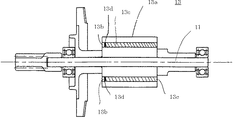
本発明の実施形態に係るインパクトドライバ50は、後述するブラシレスモータ3の回転軸11と同一方向に沿って、一端部(図面の左端部)から他端部(図面の右端部)に延在し、モータ3を収納する合成樹脂材料のモータハウジング部50aと、モータハウジング部50aの他端部に連続して形成された、動力伝達機構部4を収容する動力伝達ハウジング部50bと、モータハウジング部50aおよび動力伝達ハウジング部50bから垂下するハンドルハウジング部50cとから構成された工具本体を含み、動力伝達ハウジング部50bの先端部はアンビル10の端部が突出し、アンビル角穴部10aには先端工具、例えばドライバビット(図示なし)を着脱自在に差し込んで取付部材10bによって固定できるように構成されている。アンビル角穴部10aには、他の先端工具としてボルト締付用ビットも装着することができる。
The
モータハウジング部50aは筒状の形状を有し、その内周部内には、駆動源となるブラシレスDCモータ3が収容または装着される。ブラシレスモータ3のモータハウジング部50aへの装着構造については後述する。
The motor housing portion 50a has a cylindrical shape, and a
モータハウジング部50aに連続する動力伝達ハウジング部50b内にはモータ3の回転力を回転打撃力としてアンビル10に伝達するための動力伝達機構部4が収容されている。動力伝達機構部4は、遊星ギア6とリングギア7で構成される減速機構部と、スピンドル8およびスピンドル8上に前後摺動可能に配され、かつスプリング5によって打撃力が与えられるハンマ9から成るインパクト機構部と、ハンマ9によって回転打撃力が与えられ、上述のように先端工具(図示なし)を保持可能なアンビル10とで構成される。
A power transmission mechanism portion 4 for transmitting the rotational force of the
ハンドルハウジング部50cには、モータ3の駆動電源となる電池パック1がハンドルハウジング部50cの下端部に着脱可能に装着されている。電池パックケース1は、図示されないリチウムイオン二次電池、ニッケル・カドミウム二次電池等から成る電池パック本体を収容し、該電池パック本体の大半はハンドルハウジング部50c内に挿入され、収容される。電池パックケース1は、ハンドルハウジング部50cの一部に設けられたトリガスイッチ50dを介してモータ駆動回路装置2に電気的接続されている。モータ駆動回路装置2は、後述するブラシレスモータ3のステータコイル12a(例えば、スター結線された3相コイル)に電気的接続され、モータ3のロータ13を回転駆動させる。
A battery pack 1 serving as a drive power source for the
モータを電気的に駆動させるには、ブラシレスモータ3のステータコイル12aに駆動電流を通電するための周知のブリッジ回路から成るインバータ回路22と、インバータ回路22を制御するCPU等から成るモータ駆動回路装置2が必要となる。特に、インバータ回路22には、ステータコイル12aに大駆動電流を通電する必要があり、スイッチング素子として動作するIGBT(絶縁ゲートバイポーラトランジスタ)のような大容量の出力トランジスタを使用しなければならない。このため出力トランジスタの電力損失が大きくなり、発熱が問題となるため放熱する必要がある。吸気口17に近接した位置に出力トランジスタ21の金属(放熱板)21a側を配置し、放熱部材を別に設けない構造としている。
In order to electrically drive the motor, a motor drive circuit device comprising an
以上のように構成されたインパクトドライバ50によれば、作業者がハンドルハウジング部50cを把持しながら、トリガスイッチ50dを引けば、トリガスイッチ50dがオン状態となり、インパクトドライバ50の動作を開始できる。ねじ締め作業時、回転軸11から伝達されたモータ3の回転力を遊星ギア6とリングギア7で減速し、その回転力をスピンドル8に伝達すると共に、ネジ締め中にアンビル10(先端工具)に所定以上の負荷トルクがかかるとスプリング5の作用によりハンマ9は回転力を打撃力へと変換する。これによりハンマ9はアンビル10に装着されている先端工具に回転打撃力を与えてネジを締め付けることができる。
According to the
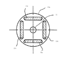
図2にロータ13の拡大図を示す。ロータコア13aに埋め込まれた複数個の永久磁石部材13cはロータコア13a全長よりも短く構成されていおり、ロータコア端部に複数個の凹室部13bを形成することができる。
FIG. 2 shows an enlarged view of the
ロータアンバランス量が大きい場合、複数個の前記凹室部13bの内部にバランス修正用接着剤13dを埋め込むことでロータ13全体のバランス量を修正可能となる。また、凹室部13bの内部にバランス修正用接着剤13dを埋め込んでいるのでロータ13が高速運転してもバランス修正用接着剤は凹部室に覆われていることでが飛散することがない。
When the rotor unbalance amount is large, the balance amount of the
1:電池パック 2:モータ駆動回路装置 3:ブラシレスモータ 4:動力伝達機構部 5:スプリング 6:遊星ギア 7:リングギア 8:スピンドル 9:ハンマ 10:アンビル 10a:アンビル角穴部 10b:先端工具取付部材 11:回転軸 11a:軸受部材 12:ステータ 12a:ステータコイル 12b:ステータの内周部 12c:ステータの外周部 12d:ステータの一端部 12e:ステータの他端部 12f:ステータのスロット 13:ロータ 13a:ロータコア 13b:凹室 13c:永久磁石部材 13d:バランス修正用接着剤 15:冷却ファン 16:空間部 17:吸気口 18:排気口 19:空気通路 20:冷却風(冷却気体) 21:出力トランジスタ 21a:出力トランジスタの金属(放熱板)側 22:インバータ回路基板 31:コントローラクミ 50:電動工具(インパクトドライバ) 50a:モータハウジング部 50b:動力伝達ハウジング部 50c:ハンドルハウジング部 50e:モータハウジングの端壁部
1: Battery pack 2: Motor drive circuit device 3: Brushless motor 4: Power transmission mechanism 5: Spring 6: Planetary gear 7: Ring gear 8: Spindle 9: Hammer 10: Anvil 10a: Anvil square hole 10b: Tip tool Mounting member 11: Rotating shaft 11a: Bearing member 12:
Claims (3)
前記ハウジングに固定されるステータと、前記ステータに対して回転可能なロータと、を有するブラシレスモータと、 A brushless motor having a stator fixed to the housing and a rotor rotatable with respect to the stator;
前記ロータによって駆動される先端工具取付部材と、を有する電動工具であって、 A power tool having a tip tool attachment member driven by the rotor,
前記ロータは、ロータコアと、前記ロータコアに埋め込まれ前記ロータコアよりも全長が短い複数個の永久磁石と、を有し、 The rotor has a rotor core and a plurality of permanent magnets embedded in the rotor core and having a shorter overall length than the rotor core,
前記ロータコアに前記永久磁石を埋め込んだ際に形成される凹室部に、接着剤が埋め込まれることを特徴とする電動工具。 An electric power tool, wherein an adhesive is embedded in a concave chamber formed when the permanent magnet is embedded in the rotor core.
前記ロータの前面に前記凹室部が配置されることを特徴とする請求項1記載の電動工具。 The power tool according to claim 1, wherein the concave chamber portion is disposed on a front surface of the rotor.
Priority Applications (1)
| Application Number | Priority Date | Filing Date | Title |
|---|---|---|---|
| JP2008086590A JP5092844B2 (en) | 2008-03-28 | 2008-03-28 | Electric tool |
Applications Claiming Priority (1)
| Application Number | Priority Date | Filing Date | Title |
|---|---|---|---|
| JP2008086590A JP5092844B2 (en) | 2008-03-28 | 2008-03-28 | Electric tool |
Publications (3)
| Publication Number | Publication Date |
|---|---|
| JP2009240140A JP2009240140A (en) | 2009-10-15 |
| JP2009240140A5 JP2009240140A5 (en) | 2011-04-14 |
| JP5092844B2 true JP5092844B2 (en) | 2012-12-05 |
Family
ID=41253411
Family Applications (1)
| Application Number | Title | Priority Date | Filing Date |
|---|---|---|---|
| JP2008086590A Expired - Fee Related JP5092844B2 (en) | 2008-03-28 | 2008-03-28 | Electric tool |
Country Status (1)
| Country | Link |
|---|---|
| JP (1) | JP5092844B2 (en) |
Cited By (1)
| Publication number | Priority date | Publication date | Assignee | Title |
|---|---|---|---|---|
| CN103715847A (en) * | 2013-11-30 | 2014-04-09 | 浙江京马电机有限公司 | Rotor dynamic balance adjusting method |
Families Citing this family (2)
| Publication number | Priority date | Publication date | Assignee | Title |
|---|---|---|---|---|
| JP6334914B2 (en) * | 2013-12-25 | 2018-05-30 | 株式会社マキタ | Electric tool |
| JP2015126563A (en) * | 2013-12-25 | 2015-07-06 | 株式会社マキタ | Electric tool |
Family Cites Families (5)
| Publication number | Priority date | Publication date | Assignee | Title |
|---|---|---|---|---|
| JP3821184B2 (en) * | 1998-03-27 | 2006-09-13 | 株式会社富士通ゼネラル | Permanent magnet motor |
| JP2001037174A (en) * | 1999-07-23 | 2001-02-09 | Sankyo Seiki Mfg Co Ltd | Rotation balance adjusting method of rotor, and rotor subjected to balance adjustment there by |
| JP2004159474A (en) * | 2002-11-08 | 2004-06-03 | Matsushita Electric Ind Co Ltd | Rotor and motor provided therewith |
| JP2006109595A (en) * | 2004-10-04 | 2006-04-20 | Japan Servo Co Ltd | Rotor balance correction structure of outer rotor type motor |
| JP4986258B2 (en) * | 2005-12-27 | 2012-07-25 | 日立工機株式会社 | Electric tool |
-
2008
- 2008-03-28 JP JP2008086590A patent/JP5092844B2/en not_active Expired - Fee Related
Cited By (1)
| Publication number | Priority date | Publication date | Assignee | Title |
|---|---|---|---|---|
| CN103715847A (en) * | 2013-11-30 | 2014-04-09 | 浙江京马电机有限公司 | Rotor dynamic balance adjusting method |
Also Published As
| Publication number | Publication date |
|---|---|
| JP2009240140A (en) | 2009-10-15 |
Similar Documents
| Publication | Publication Date | Title |
|---|---|---|
| JP4487836B2 (en) | Electric tool | |
| US10040178B2 (en) | Power tool and rotary impact tool | |
| JP5333719B2 (en) | Electric tool | |
| US9731410B2 (en) | Power tool | |
| US8986076B2 (en) | Direct motor-drive portable angle grinder | |
| EP2532488B1 (en) | Electric tools | |
| US8338997B2 (en) | Power tool | |
| US9126316B2 (en) | Electric tool | |
| JP5190774B2 (en) | Electric tool | |
| WO2016067997A1 (en) | Powered working machine | |
| JP5170677B2 (en) | Electric tool | |
| JP5353380B2 (en) | Electric tool | |
| JP5092844B2 (en) | Electric tool | |
| JP5082717B2 (en) | Electric tool | |
| JP2015223658A (en) | Electric tool and rotary impact tool | |
| JP4998079B2 (en) | Electric tool | |
| JP7070337B2 (en) | Electrical equipment | |
| JP5170624B2 (en) | Flat cable protection structure | |
| JP5057145B2 (en) | Electric tool | |
| JP4947490B2 (en) | Electric tool | |
| JP5541324B2 (en) | Electric tool | |
| JP5062473B2 (en) | Electric tool | |
| JP2024043274A (en) | electrical equipment | |
| JP2023133009A (en) | Electric power tool | |
| JP2023038057A (en) | Electric tool |
Legal Events
| Date | Code | Title | Description |
|---|---|---|---|
| A521 | Written amendment |
Free format text: JAPANESE INTERMEDIATE CODE: A523 Effective date: 20110225 |
|
| A621 | Written request for application examination |
Free format text: JAPANESE INTERMEDIATE CODE: A621 Effective date: 20110225 |
|
| A977 | Report on retrieval |
Free format text: JAPANESE INTERMEDIATE CODE: A971007 Effective date: 20120815 |
|
| TRDD | Decision of grant or rejection written | ||
| A01 | Written decision to grant a patent or to grant a registration (utility model) |
Free format text: JAPANESE INTERMEDIATE CODE: A01 Effective date: 20120821 |
|
| A01 | Written decision to grant a patent or to grant a registration (utility model) |
Free format text: JAPANESE INTERMEDIATE CODE: A01 |
|
| A61 | First payment of annual fees (during grant procedure) |
Free format text: JAPANESE INTERMEDIATE CODE: A61 Effective date: 20120903 |
|
| R150 | Certificate of patent or registration of utility model |
Free format text: JAPANESE INTERMEDIATE CODE: R150 |
|
| FPAY | Renewal fee payment (event date is renewal date of database) |
Free format text: PAYMENT UNTIL: 20150928 Year of fee payment: 3 |
|
| LAPS | Cancellation because of no payment of annual fees |