JP5089587B2 - Solution manufacturing system and method - Google Patents
Solution manufacturing system and method Download PDFInfo
- Publication number
- JP5089587B2 JP5089587B2 JP2008524090A JP2008524090A JP5089587B2 JP 5089587 B2 JP5089587 B2 JP 5089587B2 JP 2008524090 A JP2008524090 A JP 2008524090A JP 2008524090 A JP2008524090 A JP 2008524090A JP 5089587 B2 JP5089587 B2 JP 5089587B2
- Authority
- JP
- Japan
- Prior art keywords
- solution
- additive
- concentration
- mixture
- container
- Prior art date
- Legal status (The legal status is an assumption and is not a legal conclusion. Google has not performed a legal analysis and makes no representation as to the accuracy of the status listed.)
- Active
Links
Images


Classifications
-
- B—PERFORMING OPERATIONS; TRANSPORTING
- B01—PHYSICAL OR CHEMICAL PROCESSES OR APPARATUS IN GENERAL
- B01F—MIXING, e.g. DISSOLVING, EMULSIFYING OR DISPERSING
- B01F21/00—Dissolving
-
- B—PERFORMING OPERATIONS; TRANSPORTING
- B01—PHYSICAL OR CHEMICAL PROCESSES OR APPARATUS IN GENERAL
- B01F—MIXING, e.g. DISSOLVING, EMULSIFYING OR DISPERSING
- B01F21/00—Dissolving
- B01F21/15—Dissolving comprising constructions for blocking or redispersing undissolved solids, e.g. sieves, separators or guiding constructions
-
- B—PERFORMING OPERATIONS; TRANSPORTING
- B01—PHYSICAL OR CHEMICAL PROCESSES OR APPARATUS IN GENERAL
- B01F—MIXING, e.g. DISSOLVING, EMULSIFYING OR DISPERSING
- B01F21/00—Dissolving
- B01F21/30—Workflow diagrams or layout of plants, e.g. flow charts; Details of workflow diagrams or layout of plants, e.g. controlling means
-
- B—PERFORMING OPERATIONS; TRANSPORTING
- B01—PHYSICAL OR CHEMICAL PROCESSES OR APPARATUS IN GENERAL
- B01F—MIXING, e.g. DISSOLVING, EMULSIFYING OR DISPERSING
- B01F25/00—Flow mixers; Mixers for falling materials, e.g. solid particles
- B01F25/50—Circulation mixers, e.g. wherein at least part of the mixture is discharged from and reintroduced into a receptacle
- B01F25/53—Circulation mixers, e.g. wherein at least part of the mixture is discharged from and reintroduced into a receptacle in which the mixture is discharged from and reintroduced into a receptacle through a recirculation tube, into which an additional component is introduced
-
- B—PERFORMING OPERATIONS; TRANSPORTING
- B01—PHYSICAL OR CHEMICAL PROCESSES OR APPARATUS IN GENERAL
- B01F—MIXING, e.g. DISSOLVING, EMULSIFYING OR DISPERSING
- B01F35/00—Accessories for mixers; Auxiliary operations or auxiliary devices; Parts or details of general application
-
- B—PERFORMING OPERATIONS; TRANSPORTING
- B01—PHYSICAL OR CHEMICAL PROCESSES OR APPARATUS IN GENERAL
- B01F—MIXING, e.g. DISSOLVING, EMULSIFYING OR DISPERSING
- B01F35/00—Accessories for mixers; Auxiliary operations or auxiliary devices; Parts or details of general application
- B01F35/10—Maintenance of mixers
- B01F35/145—Washing or cleaning mixers not provided for in other groups in this subclass; Inhibiting build-up of material on machine parts using other means
- B01F35/1452—Washing or cleaning mixers not provided for in other groups in this subclass; Inhibiting build-up of material on machine parts using other means using fluids
- B01F35/1453—Washing or cleaning mixers not provided for in other groups in this subclass; Inhibiting build-up of material on machine parts using other means using fluids by means of jets of fluid, e.g. air
-
- B—PERFORMING OPERATIONS; TRANSPORTING
- B01—PHYSICAL OR CHEMICAL PROCESSES OR APPARATUS IN GENERAL
- B01F—MIXING, e.g. DISSOLVING, EMULSIFYING OR DISPERSING
- B01F35/00—Accessories for mixers; Auxiliary operations or auxiliary devices; Parts or details of general application
- B01F35/20—Measuring; Control or regulation
- B01F35/21—Measuring
- B01F35/211—Measuring of the operational parameters
- B01F35/2112—Level of material in a container or the position or shape of the upper surface of the material
-
- B—PERFORMING OPERATIONS; TRANSPORTING
- B01—PHYSICAL OR CHEMICAL PROCESSES OR APPARATUS IN GENERAL
- B01F—MIXING, e.g. DISSOLVING, EMULSIFYING OR DISPERSING
- B01F35/00—Accessories for mixers; Auxiliary operations or auxiliary devices; Parts or details of general application
- B01F35/20—Measuring; Control or regulation
- B01F35/21—Measuring
- B01F35/213—Measuring of the properties of the mixtures, e.g. temperature, density or colour
-
- B—PERFORMING OPERATIONS; TRANSPORTING
- B01—PHYSICAL OR CHEMICAL PROCESSES OR APPARATUS IN GENERAL
- B01F—MIXING, e.g. DISSOLVING, EMULSIFYING OR DISPERSING
- B01F35/00—Accessories for mixers; Auxiliary operations or auxiliary devices; Parts or details of general application
- B01F35/20—Measuring; Control or regulation
- B01F35/21—Measuring
- B01F35/2132—Concentration, pH, pOH, p(ION) or oxygen-demand
-
- B—PERFORMING OPERATIONS; TRANSPORTING
- B01—PHYSICAL OR CHEMICAL PROCESSES OR APPARATUS IN GENERAL
- B01F—MIXING, e.g. DISSOLVING, EMULSIFYING OR DISPERSING
- B01F35/00—Accessories for mixers; Auxiliary operations or auxiliary devices; Parts or details of general application
- B01F35/20—Measuring; Control or regulation
- B01F35/22—Control or regulation
- B01F35/2201—Control or regulation characterised by the type of control technique used
- B01F35/2202—Controlling the mixing process by feed-back, i.e. a measured parameter of the mixture is measured, compared with the set-value and the feed values are corrected
-
- B—PERFORMING OPERATIONS; TRANSPORTING
- B01—PHYSICAL OR CHEMICAL PROCESSES OR APPARATUS IN GENERAL
- B01F—MIXING, e.g. DISSOLVING, EMULSIFYING OR DISPERSING
- B01F35/00—Accessories for mixers; Auxiliary operations or auxiliary devices; Parts or details of general application
- B01F35/20—Measuring; Control or regulation
- B01F35/22—Control or regulation
- B01F35/2201—Control or regulation characterised by the type of control technique used
- B01F35/2205—Controlling the mixing process from a remote server, e.g. by sending commands using radio, telephone, internet, local network, GPS or other means
-
- G—PHYSICS
- G05—CONTROLLING; REGULATING
- G05D—SYSTEMS FOR CONTROLLING OR REGULATING NON-ELECTRIC VARIABLES
- G05D11/00—Control of flow ratio
- G05D11/02—Controlling ratio of two or more flows of fluid or fluent material
- G05D11/13—Controlling ratio of two or more flows of fluid or fluent material characterised by the use of electric means
- G05D11/135—Controlling ratio of two or more flows of fluid or fluent material characterised by the use of electric means by sensing at least one property of the mixture
-
- G—PHYSICS
- G05—CONTROLLING; REGULATING
- G05D—SYSTEMS FOR CONTROLLING OR REGULATING NON-ELECTRIC VARIABLES
- G05D21/00—Control of chemical or physico-chemical variables, e.g. pH value
- G05D21/02—Control of chemical or physico-chemical variables, e.g. pH value characterised by the use of electric means
-
- B—PERFORMING OPERATIONS; TRANSPORTING
- B01—PHYSICAL OR CHEMICAL PROCESSES OR APPARATUS IN GENERAL
- B01F—MIXING, e.g. DISSOLVING, EMULSIFYING OR DISPERSING
- B01F35/00—Accessories for mixers; Auxiliary operations or auxiliary devices; Parts or details of general application
- B01F35/50—Mixing receptacles
- B01F35/512—Mixing receptacles characterised by surface properties, e.g. coated or rough
-
- Y—GENERAL TAGGING OF NEW TECHNOLOGICAL DEVELOPMENTS; GENERAL TAGGING OF CROSS-SECTIONAL TECHNOLOGIES SPANNING OVER SEVERAL SECTIONS OF THE IPC; TECHNICAL SUBJECTS COVERED BY FORMER USPC CROSS-REFERENCE ART COLLECTIONS [XRACs] AND DIGESTS
- Y10—TECHNICAL SUBJECTS COVERED BY FORMER USPC
- Y10S—TECHNICAL SUBJECTS COVERED BY FORMER USPC CROSS-REFERENCE ART COLLECTIONS [XRACs] AND DIGESTS
- Y10S422/00—Chemical apparatus and process disinfecting, deodorizing, preserving, or sterilizing
- Y10S422/902—Sodium chloride and potassium chloride dissolver
-
- Y—GENERAL TAGGING OF NEW TECHNOLOGICAL DEVELOPMENTS; GENERAL TAGGING OF CROSS-SECTIONAL TECHNOLOGIES SPANNING OVER SEVERAL SECTIONS OF THE IPC; TECHNICAL SUBJECTS COVERED BY FORMER USPC CROSS-REFERENCE ART COLLECTIONS [XRACs] AND DIGESTS
- Y10—TECHNICAL SUBJECTS COVERED BY FORMER USPC
- Y10T—TECHNICAL SUBJECTS COVERED BY FORMER US CLASSIFICATION
- Y10T137/00—Fluid handling
- Y10T137/0318—Processes
- Y10T137/0324—With control of flow by a condition or characteristic of a fluid
- Y10T137/0329—Mixing of plural fluids of diverse characteristics or conditions
- Y10T137/034—Controlled by conductivity of mixture
-
- Y—GENERAL TAGGING OF NEW TECHNOLOGICAL DEVELOPMENTS; GENERAL TAGGING OF CROSS-SECTIONAL TECHNOLOGIES SPANNING OVER SEVERAL SECTIONS OF THE IPC; TECHNICAL SUBJECTS COVERED BY FORMER USPC CROSS-REFERENCE ART COLLECTIONS [XRACs] AND DIGESTS
- Y10—TECHNICAL SUBJECTS COVERED BY FORMER USPC
- Y10T—TECHNICAL SUBJECTS COVERED BY FORMER US CLASSIFICATION
- Y10T137/00—Fluid handling
- Y10T137/2496—Self-proportioning or correlating systems
- Y10T137/2499—Mixture condition maintaining or sensing
- Y10T137/2509—By optical or chemical property
-
- Y—GENERAL TAGGING OF NEW TECHNOLOGICAL DEVELOPMENTS; GENERAL TAGGING OF CROSS-SECTIONAL TECHNOLOGIES SPANNING OVER SEVERAL SECTIONS OF THE IPC; TECHNICAL SUBJECTS COVERED BY FORMER USPC CROSS-REFERENCE ART COLLECTIONS [XRACs] AND DIGESTS
- Y10—TECHNICAL SUBJECTS COVERED BY FORMER USPC
- Y10T—TECHNICAL SUBJECTS COVERED BY FORMER US CLASSIFICATION
- Y10T436/00—Chemistry: analytical and immunological testing
- Y10T436/11—Automated chemical analysis
- Y10T436/115831—Condition or time responsive
Abstract
Description
本発明の態様は、化学溶液(例えば、塩水溶液)を製造するために用いられる装置、方法および制御システムに関する。さらに詳細には、本発明の態様は、化学物質を溶媒に溶解し、特定の濃度の溶液を製造するための装置に関する。 Aspects of the invention relate to apparatus, methods and control systems used to produce chemical solutions (eg, saline solutions). More particularly, embodiments of the present invention relate to an apparatus for dissolving a chemical in a solvent to produce a specific concentration solution.
本願は、2005年7月27日に提出された米国出願第11/190,395号の一部係属出願であり、本願では、その内容を参考のために援用する。 This application is a partially pending application of US Application No. 11 / 190,395 filed July 27, 2005, the contents of which are incorporated herein by reference.
特定の濃度で溶媒に溶解された化学物質は、無数の産業用途に用いられている。例えば、道路、歩道、私道およびその他の表面から雪および氷の量を減少させるために食塩水を適用することは、一般に行われている産業的手法である。食塩水は、一般に、岩塩と水とを混合して溶液を製造することによって生成される。次に、溶液の濃度は、淡水を添加して混合物を希釈するか、または塩を添加して混合物を濃縮させることによって調整され得る。約23〜27重量%の溶液が、氷および雪(ここで、塩化ナトリウムは、塩類の少なくとも1種である)を除去するのに十分である。この濃度範囲では、溶液は、華氏約−10度の周囲温度で氷および雪を溶かす。所望の濃度が溶液中で維持されず、路上において適正量で適用されない場合には、事故が発生し得る。例えば、混合物中の塩が少なすぎると、水の凝固点を周囲条件未満に低下させることができなくなり、すでに蓄積されている氷を溶かすどころか、車道の氷結を促進し得るような混合物となる。 Chemicals dissolved in a solvent at a specific concentration are used in myriad industrial applications. For example, the application of saline to reduce the amount of snow and ice from roads, sidewalks, driveways and other surfaces is a common industrial practice. Saline is generally produced by mixing rock salt and water to produce a solution. The concentration of the solution can then be adjusted by adding fresh water to dilute the mixture, or by adding salt to concentrate the mixture. About 23-27% by weight solution is sufficient to remove ice and snow, where sodium chloride is at least one of the salts. In this concentration range, the solution melts ice and snow at an ambient temperature of about -10 degrees Fahrenheit. An accident can occur if the desired concentration is not maintained in solution and is not applied in the proper amount on the road. For example, if there is too little salt in the mixture, the freezing point of water cannot be lowered below ambient conditions, resulting in a mixture that can promote freezing on the roadway, rather than melting the already accumulated ice.
溶液の濃度を監視および調整する1つの方法として、溶液の比重を測定し、所望の比重が得られるまで、溶媒(塩によっては淡水の場合がある)を溶液に添加することが挙げられる。このように、この方法によると、溶液の比重は溶液の濃度に関連づけられる。少なくとも1つの従来のシステムは、車道、歩道、私道および滑走路に噴霧して雪および氷を溶かすために用いられる液体防氷剤として使用される食塩水を製造するための水中に溶解された大量の岩塩または酢酸カルシウムマグネシウム(CMA)ペレットを製造する。電子比重計(比重測定デバイス)は、塩水/水溶液の比重を測定する。比重が高すぎたり低すぎたりすると、弁が開閉され、混合物への淡水の量が調整される。このように、混合物は、所望の塩度に調整される。 One way to monitor and adjust the concentration of the solution is to measure the specific gravity of the solution and add a solvent (which may be fresh water depending on the salt) to the solution until the desired specific gravity is obtained. Thus, according to this method, the specific gravity of the solution is related to the concentration of the solution. At least one conventional system is a large amount dissolved in water to produce saline used as a liquid deicer used to melt snow and ice by spraying on roadways, sidewalks, driveways and runways. Of rock salt or calcium magnesium acetate (CMA) pellets. An electronic hydrometer (specific gravity measuring device) measures the specific gravity of the salt water / water solution. If the specific gravity is too high or too low, the valve is opened and closed, and the amount of fresh water to the mixture is adjusted. In this way, the mixture is adjusted to the desired salinity.
上記のように、濃度の指標として比重を用いる、食塩水を製造するための方法では、比重が濃度に関連づけられる。この相関関係は、場合によっては、間違っていることがある。例えば、溶液中のシリカ、埃およびその他の異物などの固体は、溶液の比重および/または測定デバイスの測定値に影響を与えることがある。この結果、混合溶液中の変動に基づくと、溶液にとって望ましくない塩濃度レベルとなり得る。さらに、比重に基づく測定値は、一般に、1回または複数の混合動作中の連続した測定値ではなく、時間およびプロセス上間隔を置いた一連の別個の測定値である。 As described above, in a method for producing saline using specific gravity as an indicator of concentration, specific gravity is related to concentration. This correlation may be wrong in some cases. For example, solids such as silica, dust and other foreign substances in the solution may affect the specific gravity of the solution and / or the measurement value of the measuring device. This can result in undesirable salt concentration levels for the solution based on variations in the mixed solution. In addition, specific gravity based measurements are generally a series of discrete measurements spaced in time and process, rather than consecutive measurements during one or more mixing operations.
また、他の混合システムは、単一指向性であり、混合動作で起こり得る変動を明らかににするものではなく、それにより、濃度が低すぎるかまたは高すぎる混合物が提供される。 Also, other mixing systems are unidirectional and do not account for possible variations in mixing operation, thereby providing a mixture that is too low or too high.
このように、当該技術分野において、正確な濃度レベルの混合物を製造する装置および方法が求められている。 Thus, there is a need in the art for an apparatus and method for producing a mixture of accurate concentration levels.
この要旨は、詳細な説明において以下にさらに記載される簡略化された形式での様々な概念を紹介するために提供される。この要旨は、請求項に記載される主題の重要な特徴または本質的な特徴を特定するものではない。 This summary is provided to introduce a selection of concepts in a simplified form that are further described below in the detailed description. This summary is not intended to identify key features or essential features of the claimed subject matter.
本願は、化合物および/または添加物を組合せるための改善されたシステムおよび方法を開示している。記載されるシステムおよび方法によると、所望の濃度の化学物質を用いて溶液を製造することが可能である。あるいは、すくなとも特定の濃度または多くとも特定の濃度の化学物質を用いて溶液を製造することができる。システムは、化学物質を混合することが可能な領域と、溶液をさらに濃縮または希釈する必要があるかどうかを検出するために用いられる濃度センサとを有する。濃度が目標濃度の公差範囲内である場合、溶液は、貯蔵タンクまたは他の容器に分流され得る。 The present application discloses improved systems and methods for combining compounds and / or additives. According to the described system and method, it is possible to produce solutions with the desired concentration of chemicals. Alternatively, the solution can be made using chemicals at least a specific concentration or at most a specific concentration. The system has an area where chemicals can be mixed and a concentration sensor used to detect whether the solution needs to be further concentrated or diluted. If the concentration is within the tolerance range of the target concentration, the solution can be diverted to a storage tank or other container.
多数の実施形態が開示されているが、本発明のさらに他の実施形態も、本発明の例示的な実施形態を示して説明する以下の詳細な説明から当業者に明白になるであろう。理解できるように、本発明は、本発明の趣旨および範囲から逸脱せずに、様々な自明の態様において改変可能である。従って、図面および詳細な説明は、本質的には例示されるもので、限定するものではない。 While numerous embodiments have been disclosed, still other embodiments of the present invention will become apparent to those skilled in the art from the following detailed description, which illustrates and describes exemplary embodiments of the present invention. As will be realized, the invention is capable of modifications in various obvious aspects, without departing from the spirit and scope of the invention. Accordingly, the drawings and detailed description are illustrative in nature and not restrictive.
添付の図面を参照しながら例示的な実施形態の以下の説明を参照することによって、本発明およびその潜在的な利点をより完全に理解することができるであろう。 A more complete understanding of the present invention and its potential advantages will be obtained by reference to the following description of illustrative embodiments thereof with reference to the accompanying drawings.
上記で要約した様々な態様は、様々な形態で具現化され得る。 The various aspects summarized above may be embodied in various forms.
以下の説明は、態様が実施され得る様々な組合せおよび構成を例示することによって示される。記載される態様および/または実施形態は、単に例であって、他の態様および/または実施形態も用いられ、本開示の範囲を逸脱せずに、構造および機能的改変が行われ得ることを理解されたい。 The following description is presented by way of illustration of various combinations and configurations in which aspects may be implemented. The described aspects and / or embodiments are merely examples, and other aspects and / or embodiments may be used and structural and functional modifications may be made without departing from the scope of the present disclosure. I want you to understand.
以下の説明では、要素間の様々な接続が提示されることに留意されたい。これらの接続は、一般に、特に記載のない限り、直接的または間接的であり、本明細書はこの点において限定するものではないことに留意されたい。 Note that in the following description, various connections between elements are presented. It should be noted that these connections are generally direct or indirect unless otherwise stated, and the specification is not limited in this respect.
本記載は、本発明の態様をユーザが理解できるように、6つのセクションに分類されている。これらのセクションには、以下のものが含まれる。 The description is divided into six sections so that users can understand aspects of the invention. These sections include the following:
a.溶液製造機
b.添加物
c.分配
d.化学物質、溶液および溶媒
e.改変
f.実施形態および応用
≪溶液製造機≫
溶液製造機が提供される。さらに具体的には、本発明の態様は、溶液の濃度を測定し、溶液に添加される溶媒の量を決定し、その量の溶媒を溶液に添加することによって、所望の濃度で食塩水などの溶液を製造する装置および方法を提供する。本願全体にわたって、溶媒と、部分的または全体的に溶解した化学物質との任意の組合せである溶液をスラリーと呼んでもよい。例えば、全量未満の塩が溶媒に溶解している塩と溶媒との高濃度の混合物を、本願の目的では、スラリーと呼んでもよい。デバイスはさらに、化学物質および溶媒から沈殿物を分離し、堆積した沈殿物を流し出すように構成されてもよい。従って、デバイスは、溶解していないシリカ、埃および砂利などの異物を溶液から分離するように構成されてもよい。
a. Solution maker b. Additives c. Distribution d. Chemicals, solutions and solvents e. Modification f. Embodiment and Application << Solution Manufacturing Machine >>
A solution maker is provided. More specifically, embodiments of the present invention measure the concentration of a solution, determine the amount of solvent added to the solution, and add that amount of solvent to the solution, such as saline at a desired concentration. An apparatus and method for producing a solution of Throughout this application, a solution that is any combination of solvent and partially or wholly dissolved chemicals may be referred to as a slurry. For example, a highly concentrated mixture of salt and solvent in which less than the total amount of salt is dissolved in the solvent may be referred to as a slurry for purposes of this application. The device may be further configured to separate the precipitate from the chemical and solvent and flush the deposited precipitate. Thus, the device may be configured to separate foreign substances such as undissolved silica, dust and gravel from the solution.
溶液製造機は、ユーザが制御パネルを監視し、溶液の濃度が所望の濃度になるときを決定する手動モードで動作してもよい。あるいは、溶液製造機は、自律的に動作し、それ自体で濃度レベルを調整してもよい。さらに、溶液製造機は、いくつかの態様が自律的に処理され、他の態様がオペレータの指示に基づいて処理されるようにある範囲内で動作してもよい。 The solution maker may operate in a manual mode where the user monitors the control panel and determines when the concentration of the solution is at the desired concentration. Alternatively, the solution maker may operate autonomously and adjust the concentration level by itself. Furthermore, the solution maker may operate within a range such that some aspects are processed autonomously and other aspects are processed based on operator instructions.
1つの実施形態では、溶液製造機は、1つまたはそれ以上の塩類(例えば、塩化ナトリウム)を水または他の溶媒に溶解することによって清浄な塩水溶液を製造するように構成されてもよい。他の実施形態では、溶液製造機は、他の化学物質を溶解するために用いられてもよい。その例としては、酢酸カルシウムマグネシウム、塩化カルシウム、塩化マグネシウム、酢酸カリウム、ギ酸カリウム、ギ酸ナトリウム、酢酸マグネシウム、燐酸ジアンモニウム、燐酸モノアンモニウム、尿素、エチルグリコール、プロピレングリコール、および他の化学物質が挙げられる。溶液製造機は、所望の目標濃度、所望の目標濃度範囲、または目標濃度以上の濃度を有する溶液を製造してもよい。溶液製造機はまた、すでに製造されている溶液またはスラリーを希釈することもできる。 In one embodiment, the solution maker may be configured to produce a clean saline solution by dissolving one or more salts (eg, sodium chloride) in water or other solvent. In other embodiments, the solution maker may be used to dissolve other chemicals. Examples include calcium magnesium acetate, calcium chloride, magnesium chloride, potassium acetate, potassium formate, sodium formate, magnesium acetate, diammonium phosphate, monoammonium phosphate, urea, ethyl glycol, propylene glycol, and other chemicals. It is done. The solution maker may produce a solution having a desired target concentration, a desired target concentration range, or a concentration greater than or equal to the target concentration. The solution maker can also dilute an already manufactured solution or slurry.
図1〜図3に示されるように、溶液製造機100の1つの態様は、第1コンテナ104および第2コンテナ106を含む混合器102を有し得る。混合器102に適切な容積の例としては、5立法ヤードが挙げられる。第1コンテナ104と第2コンテナ106とは、格子(グレート)142によって分離されている。第1コンテナ104は、溶媒に溶解するための化学物質を受け、溶液を製造するように形成されている。塩水溶液を製造するために、成分は、例えば、塩化ナトリウム(NaClもしくは塩)、または硫酸カルシウムマグネシウムであり得る。化学物質は、任意の適切な形態で提供され得る。例えば、化学物質が塩である場合、塩は、ペレットまたは岩の形態で提供され得る。他の溶液を製造するには他の成分が用いられ得る。以下にさらに詳細に説明されるように、溶液製造機は、様々な溶液を製造するために様々な化学物質または溶媒とともに用いられるように較正されてもよい。1つの実施形態では、溶液製造機は、塩化ナトリウムと淡水とを混合し、塩水溶液を製造する。第1部分における化学物質は、化学床(chemical bed)を提供し得る。例えば、塩水溶液を製造する際、塩床(salt bed)が第1コンテナ104内に形成され得る。
As shown in FIGS. 1-3, one aspect of the
第1コンテナ104はさらに、化学物質と混合するための溶媒を受け、所望の溶液を製造するように形成されている。塩水製造機の様々な成分は、下方へ流れ、溶媒は、重力により第1コンテナ104内の化学床を通過する。溶媒は、任意の適切な方法で第1コンテナ104に移送され得る。混合器102に連結する溶媒ラインが設けられてもよい。溶媒が凍結するのを防ぐために、オプションの自己調節加熱素子が溶媒ラインに結合されもよい。図1の実施形態では、溶媒は、溶媒入口138からの流れを駆動する溶媒弁136を介して送達される。溶媒弁136は、電気駆動弁として設けられ、弁駆動は、プログラマブルロジックコントローラ(PLC)216などの制御器によって制御され得る(図12を参照)。多くのタイプの制御器が用いられ得るが、PLCという用語は、簡単のため、本発明の様々な態様における制御器を記載する際に用いられる。弁の駆動は、1つまたはそれ以上の液面センサに依存し、および/またはオペレータもしくは自動動作とオペレータ制御との組合せによって制御され得る。以下にさらに詳細に説明され、図3に示されるように、第1液面センサ118、第2液面センサ120、および第3液面センサ122が設けられてもよい。図8、図12および図19に示されるように、特定の実施形態では、溶媒入口138は、加圧されてもよく、溶媒弁136、導管200、手動弁186、手動弁158、導管176およびスプレーヘッド178を介して希釈弁134まで、溶媒を溶液製造機100に供給していもよい。新鮮溶媒弁136はさらに、手動オーバーライドを含んでいてもよい。言うまでもなく、本明細書では、特定の構造について記載しているが、本発明の範囲内の溶液製造機は、当業者によって理解されるように、より少ないまたはより多くの構成要素のパーツを含んでいてもよい。
The
格子142は、化学物質が溶媒中で溶解される前に、混合器102の第1コンテナ104から混合器102の第2コンテナ106へ通過するのを実質的に防止する。格子142には、穿孔が設けられていてもよい。溶媒および溶解した化学物質を含む溶液が第1コンテナ104中で形成されるとき、溶液は、格子142内の穿孔により、格子142を通って混合器102の第2コンテナ106まで到達する。図5は、溶液製造機と共に使用するのに適した格子142の1つの実施形態を示す。図示されるように、格子142は、複数の円形の穿孔143を含み得る。穿孔143は、直径が約3/16インチであり得る。望ましくは、穿孔143は、溶液が格子142を通過して流れるために十分大きく、化学物質が格子142を通過するのを防止するために十分小さい。従って、格子142は、化学物質を支持し、デブリを収集し、溶液を通過させるように動作する。1つの態様では、格子142は、非金属であり、1〜1/2インチのガラス繊維構造の横材を含む。
The
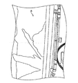
図19および図20は、溶液製造機の第1コンテナ104の内側を示す。図19において、溶媒を駆出するためのスプレーヘッド178、および格子142が示される。図20は、スプレーヘッド178を通した流れを示す。
19 and 20 show the inside of the
上記のように、1つまたはそれ以上の液面センサが設けられ得る。液面センサは、液面感知デバイスである。これらのデバイスには、信号をPLC216に送信するスイッチが設けられ得る。そのため、液面センサは、操作によって、PLC216の入力部に接続され得る。液面センサは、任意の適切なデバイスとして設けられ得る。1つの実施形態では、適切な液面センサは、マイクロスイッチを作動させるフロートデバイスを備えた機械的スイッチである。他の実施形態では、誘導容量性近接スイッチを用いてもよい。液面センサは、混合器102、さらに具体的には、混合器102の第1部分における液面を所望のレベルに維持する。一般に、高い液面は、混合器102から溢れ、流出が生じるのに対して、低い液面は、移送ポンプ124を乾燥させ、それによって、ポンプシールが損傷し得る。
As described above, one or more liquid level sensors may be provided. The liquid level sensor is a liquid level sensing device. These devices may be provided with a switch that transmits a signal to the
図3に示されるように、第1、第2および第3液面センサ118、120および122が、それぞれ、設けられている。液面センサをさらに例示するために図7および図9を参照する。いくつかの実施形態では、3つより多くの液面センサを設けてもよい。あるいは、液面センサは設けられなくてもよい。第1液面センサ118は、混合器102と当接し、第2液面センサ120にほぼ隣接し、PLC216の入力部に接続され得る。第1液面センサ118は、混合器102中の液面が低いかどうかを検出する。液面が低く、溶液製造機100が、動作(run)モードにある場合、ポンプ124は、溶液製造機100が動作モードである場合、「オフ」状態になる。これにより、ポンプ124は、乾燥することによる損傷から保護される。
As shown in FIG. 3, first, second, and third
第2液面センサ120は、第1液面センサ118および第3液面センサ122にほぼ隣接し、PLC216の入力部に接続され得る。第2液面センサ120は十分な量の水または他の溶媒が混合器102内に存在するかどうかを検出する。十分な量の溶媒を検出すると、ポンプ124は作動し、「オン」状態に切り替えられる。ポンプ124は、バッチが完了するまで、または第1液面センサ118が、液面が低いことを検出するまで、「オン」状態にラッチされる。
The second
第3液面センサ122は混合器102に当接し、第2液面センサ120にほぼ隣接し、PLC216の入力部に接続され得る。第3液面センサ122は、混合器102が所定レベルの液体を保持しているかどうかを検出する。このレベルの液体が感知されると、溶媒弁136は、「オフ」位置に切り替えられ、それによって、混合器102は溢流から保護される。
The third
混合器102の第2コンテナ106は、導管148および塩水出口弁154に接続された塩水溶液吸引管164を含む。塩水出口弁154は、出口導管148を介して移送ポンプ124に接続されている。溶媒希釈入口146およびポンプ吸引入口は、導管148に接続され得る。図示されるように、ポンプ124は、溶液センサ132と連通して設けられてもよい。
The
1つの例では、溶液センサ132は、溶液中の化学物質の濃度を測定する。1つの態様では、センサは導電率センサである。例えば、センサは、接触点のない固体状態であり、溶液の誘導磁界を測定するテロジアル(terodial)型の導電率センサである。しかし、多くの導電率センサが当該技術分野で公知である。他の態様では、溶液センサ132は、屈折計であってもよい。溶液の屈折特性は、濃度によって変化する。屈折計は、溶液の屈折率を検出し、次に、PLC216は、濃度測定値を計算し、適切に調整することが可能である。他の態様では、溶液の比重を検出するために用いられる比重計または他のデバイスが、溶液センサ132として用いられ得る。
In one example, the
溶液センサ132は、連続して測定し、PLC216に対して、周期的なスナップショットではなく、一定の入力を供給するように構成されてもよく、それによって、機械の効率は向上する。
The
あるいは、溶液センサ132の代わりに屈折計を用いることができる。溶液の屈折特性は、濃度に応じて変化する。屈折計は、溶液の屈折率を検出し、次いで、PLC216は、適宜、濃度を計算および調整することができる。
Alternatively, a refractometer can be used in place of the
他の態様では、溶液センサ132は、温度センサと組合せてもよい。このような組合せは望ましいと思われる。なぜなら、溶液センサが導電率センサである場合、溶液の電気抵抗は、濃度だけでなく温度と共に変化し得るからである。溶液センサおよび温度センサの測定値は、温度が補償された導電率測定値を得るために用いられる。この測定値は、濃度曲線に対して等式化され、その結果、温度が補償された重量百分率濃度として溶液の測定値を表すことになる。温度が補償された導電率を濃度に関連づける濃度曲線は、溶液中の化学物質に対して展開され得る。従って、例えば、塩水製造機では、塩化ナトリウム濃度曲線が用いられる。上記のように、1つの態様では、溶液センサは、溶液の温度および導電率を測定する。塩水の特性は、温度と共に変化するため、温度を測定して実際の濃度を表現することが望ましいと思われる。
In other aspects, the
あるいは、溶液センサ132は、温度センサなしで動作し得る。溶液センサ132が温度センサなしで動作することは望ましい。なぜなら、溶液センサは、温度と共に変化しない特性を直接測定するからである。また、温度を感知せずに動作させると、コストが低く、簡単であるため、望ましい。
Alternatively, the
以下にさらに詳細に記載されるように、目標濃度の公差範囲内にある溶液が貯蔵タンクへ処理され得る間に、目標温度の公差範囲外にある溶液を調整してもよい。濃度を流れの中ほどで測定および調整することによって、溶液製造機は、オペレータの介在なしに、目標濃度で溶液を連続して製造する。 As described in more detail below, solutions that are outside the target temperature tolerance range may be adjusted while solutions that are within the target concentration tolerance range may be processed into the storage tank. By measuring and adjusting the concentration in the middle of the flow, the solution maker continuously produces the solution at the target concentration without operator intervention.
図1、図12および図13を参照すると、溶液センサ132は、PLC216と操作によって連通し得る。検出された濃度に応答し、PLC216は、所望の濃度の溶液のみが確実に貯蔵タンクに分流されるように、希釈弁134または分流弁130を作動し得る。溶液の目標濃度は、任意の所望の濃度でよい。塩水溶液では、適切な目標濃度は、19.6重量%から27重量%の範囲内であり得る。例えば、目標濃度は、23.3重量%であり得る。所望の溶液濃度を確立することに加えて、所望の溶液濃度からの特定の分散を許容可能にする所望の溶液濃度公差を確立してもよい。許容可能な公差は、目標濃度の+/−0.3%であり得る。
With reference to FIGS. 1, 12, and 13, the
分流弁130は、溶液濃度が目標濃度を上回るかもしくは下回る場合には戻し管126を通して、または、溶液濃度がほぼ所望の溶液濃度内である場合には、完成品管128を通して、ポンプ124からの流れを分流する。分流弁130は、PLC216(および/またはオペレータもしくはその組合せ)によって制御され、目標濃度-対-実際の濃度に依存し得る。目標濃度の公差外にある溶液は、導管126、弁156、導管180、および撹拌ノズル166に分流され、さらに混合器102を通過し得る。繰り返すが、分流機構の特定の実施形態が提供されるが、当業者に公知の他の機構も、目標濃度の公差外または目標濃度の範囲内にある溶液を混合器102に分流するために用いられ得る。
The
戻し管126は、流れを、混合器102の第1コンテナ104内にある弁156、導管180、および撹拌ノズル166まで通過させる。溶液は戻し管126を通過し、混合器102に戻される。完成品管128は、貯蔵タンク410まで通じている(図14を参照)。分流弁136は、さらに手動オーバーライドを有していてもよい。
The
希釈弁134は、PLC216によって制御される。希釈弁134は、溶液ポンプ124と連通し得る。従って、希釈弁134は、ポンプ124が流れを通過させているとき溶液を希釈するのに十分な溶媒を通過させるように開口し、溶液センサ132は、目標の濃度に対して実際の溶液濃度を感知する。希釈弁134は、溶媒入口138と連通する。希釈弁134は、ポンプ124が流れを通過させているとき開口し、溶液センサ132は、溶液の目標濃度に対する実際の溶液濃度を感知する。希釈弁134が開口しているとき、溶媒入口138からの溶媒は、希釈弁134を通過して導管212および希釈入口146まで達する。溶媒は、混合器102の第2コンテナ106からポンプ124へと通過する溶液と合流する。希釈弁134は、過剰濃縮された溶液を目標濃度まで希釈するのに十分な溶液で希釈するため、溶液を過剰希釈しない。希釈弁134は、さらに手動オーバーライドを含んでいてもよい。
The
感知された溶液は、任意の適切な点で任意の適切な様式で希釈され得る。例えば、感知された溶液は、出口管に溶媒を添加することにより、希釈され得る。あるいは、感知された溶液は、混合器102に戻され、混合器102中でさらなる溶媒と混合されることにより希釈され得る。
The sensed solution can be diluted in any suitable manner at any suitable point. For example, the sensed solution can be diluted by adding a solvent to the outlet tube. Alternatively, the sensed solution can be returned to the
図12に示される流量測定デバイス204は、貯蔵タンクに移送された完成溶液の容量を測定するために設けられ得る。流量測定デバイス204は、PLC216と連通して設けられ得る。さらに、添加物ポンプ210、流量測定デバイス206、および作動弁208は、流れを導管128に向けるために設けられ得る。添加物ポンプ210、流量測定デバイス206および作動弁208は、以下にさらに詳細に記載されるように、貯蔵タンクに転送されるとき、添加物と溶液とを混合させるためにPLC216と連通し得る。
A
使用中、埃およびシリカなどの固体が溶液製造機を浸透し得る。これらの固体により、沈殿物が、通常、溶液製造機内に蓄積する。一般に、溶液はできるだけ汚れがない方が望ましい。溶液中の異物は、研磨性を有する。研磨性により、塩水溶液の製造および適用に関連するポンプ、流量計および弁は過剰に磨耗し得る。時間が経つにつれて溶液中の懸濁する異物によって生じた沈殿堆積物が沈殿し、貯蔵タンク中に沈殿物の層を形成する。沈殿物の洗浄には時間がかかり、機械をオフラインにする必要がある。 During use, solids such as dust and silica can penetrate the solution maker. Due to these solids, precipitates usually accumulate in the solution maker. In general, the solution should be as clean as possible. Foreign matter in the solution has abrasiveness. Due to the abrasiveness, pumps, flow meters and valves associated with the production and application of saline solutions can be excessively worn. Over time, the sediment deposit caused by suspended foreign matter in the solution settles and forms a layer of sediment in the storage tank. Cleaning the sediment takes time and requires the machine to be taken offline.
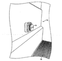
1つの実施形態では、混合器102の第2コンテナ106は、簡単に洗浄ができるように構成されている。そのため、第2コンテナ106(例えば、図3および図21を参照)は、少なくとも1つの傾斜面を有し、その傾斜面に沿って、沈殿物は、傾斜面の底部に設けられた排水だめまで滑動する。少なくとも1つの傾斜面に適切な傾斜は、約15度である。図示される実施形態では、第2コンテナ106は、第1傾斜面150、第2傾斜面152、および第3傾斜面202を有する。格子142を通過する沈殿物は、第1傾斜面150、第2傾斜面152、および第3傾斜面202で形成される排水だめ領域において混合器102の第2コンテナ106の底部で収集される。排水だめ領域は、例えば、約12インチ×12インチであり得る。簡単な洗浄を可能にするその他のコーティングも当業者に周知である。
In one embodiment, the
排水だめ出口108は、沈殿物を混合器102から流し出すために設けられ得る。このような流水洗浄は、スプレーバー402(例えば、図2および図9に示される)およびノズル162(例えば、図3に示される)を介して行われ得る。複数のノズル、例えば、排水だめの左側、右側、および後側で各壁に設けられたノズルは、排水だめを通して沈殿物を溶液製造機から強制的に出すために設けられ得る。溶液製造機は、沈殿物を流水洗浄するか、または沈殿物を手動洗浄するように構成されてもよい。さらに、沈殿物は、化学物質が混合器102の第1コンテナ104内にあるときには、混合器102から流し出され、または、混合器102の第1コンテナ104内に化学物質が実質的に存在しない場合には、混合器102から流し出され得る。混合器102における格子142は、化学物質の重量を支持し、化学物質が混合器102内にある間に沈殿物を流し出させる。
A
従って、溶液製造機は、溶解していないシリカ、埃および砂利などの異物を混合器102から分離する方法をさらに提供する。異物は、排水だめ領域に蓄積され、そこから堆積物が後に流し出され得る。さらに、溶液製造機は、混合器102の第1部分に化学物質が残存している間は、混合器102から異物の堆積物を流し出すことが可能である。
Thus, the solution maker further provides a method of separating foreign matter such as undissolved silica, dust and gravel from the
他の実施形態では、溶液製造機は、上記のような洗浄システムを備えなくてもよい。この実施形態では、混合器102は、より少ない構成要素(manufacturing)で使用され、混合器102の洗浄が必要でないか、または混合器102の定期的な洗浄が必要でない環境ではコストを削減することができる。ここで、デブリを蓄積しないか、または比較的汚れのないシステムは、洗浄なしに、混合器102と共に使用され得る。
In other embodiments, the solution maker may not include a cleaning system as described above. In this embodiment, the
いくつかの実施形態では、溶液製造機は、10,000〜20,000ポンドの塩などの化学物質を保持し得る。従って、混合器102は、負荷を支えるのに十分強固に製造される。混合器102は、任意の適切な材料で形成され得る。1つの実施形態では、混合器102を構築するための適切な材料は、ガラス繊維である。ガラス繊維は強く、塩水溶液の影響を受けない。特に、混合器102は、16,000lbの引張り強さのガラス繊維およびイソフタル酸樹脂から構築され得る。混合器102に適切な他の材料としては、限定はされないが、ステンレス鋼およびポリプロピレンが挙げられる。混合器102の内面は、セラミック樹脂でコーティングされ得る。このようなコーティングは、例えば、約0.050インチ厚であり得る。構造一体型リブは、混合器102内に設けられ、一杯の状態から空の状態まで屈曲を1インチ以内に限定し得る。1つの実施形態では、混合器102内のガラス繊維および樹脂の全体的な厚さは、約0.35インチである。リブ、角および床などの構造領域には、全体的な厚さが約0.50インチの織物ガラス繊維マットのさらなる層が設けられ得る。
In some embodiments, the solution maker may hold chemicals such as 10,000 to 20,000 pounds of salt. Thus, the
使用においては、溶液製造機は、道路から氷を除去するための塩水溶液を製造するために主要道路部門によって用いられ得る。溶液製造機は、寒い天候では屋外で用いられ得る。従って、溶液製造機は、加熱される1つまたはそれ以上の構成要素が設けられ得る。加熱素子168(例えば、図3を参照)は、混合器102内に設けられ得る。温度感知デバイスは、PLC216と連通して、混合器102内に設けられ得る。温度感知デバイスは、加熱素子168が混合器102の温度を上げるために作動される必要があるかどうかを示す。これらの素子は、サーモスタットでオン/オフ作動され、華氏32度以上の温度に耐えることができ、容器が凍結するのを防止することができる。
In use, the solution maker can be used by the main road sector to produce an aqueous salt solution for removing ice from the road. The solution maker can be used outdoors in cold weather. Thus, the solution maker can be provided with one or more components that are heated. A heating element 168 (see, eg, FIG. 3) may be provided in the
従って、混合器102は、混合器102が寒い天候で凍結する可能性を最小限に押さえるために加熱され得る。1つの実施形態では、シリコーンマットヒーターが、混合器102に構築され得る。例えば、2つの9平方フィートシリコーンマットが、混合器102に構築され得る。永久搭載されたロール防水シート(roll tarp)などのロール防水シートは、混合器102を加熱するためのヒーターに関連して使用され得る。このようなロール防水シートには、アーチおよびロール機構が設けられ、熱を中に保持し、デブリを外に出すのに有用である。ロール防水シートが設けられる場合には、ロール防水シートは、混合器102の開口頂部にわたって搭載され得る。他の加熱方法も当業者に周知である。
Thus, the
図11〜図13は溶液製造機の制御パネルの実施形態を示す。制御パネル500は、機械流れ制御デバイス、導電率センサ132、PLC216、および人間機械インターフェース(HMI)214を含み得る。他の実施形態では、PLC216は、HMI214と連通し、データログを作成する。製造され、貯蔵タンクに分流された溶液は、流量測定デバイス204(例えば、図12を参照)を介して測定され、PLCプログラム216に記録される。この測定は、フロースイッチの流量計を介して行われ得る。計算は、PLCプログラム216に導入され、製造プロセスにおける、製造される溶液の量、化学的用途、および溶媒の使用が公式化される。従って、データログは、HMI214上で見られるか、またはプリンタで印刷され得る報告書を作成する。これらの報告書は、毎日作成されてもよく、化学的および溶媒使用(添加物が溶液に導入される場合には添加物使用)だけでなく製造された溶液の動作期間合計(running season total)を示してもよい。多数のユーザ報告書が作成されてもよい。例えば、1日および期間合計が作成され、会計および請求の目的で別個に形成されてもよい。
11 to 13 show an embodiment of a control panel of a solution manufacturing machine. The
制御パネル500は、制御パネルの動作を制御する1つまたはそれ以上のプロセッサを含み得る。制御パネル500はまた、ソリッドステートメモリ(RAM、ROM、フラッシュ、磁気等)およびダイナミックメモリ(CD、DVD、ハードドライブ等)のいずれか1つを含む内部メモリを有していてもよい。制御パネルは、限定はされないが、有線インターフェース(例えば、USB、ファイアワイア、および他の有線経路)、無線インターフェース(例えば、IEEE802.11*、Wi−Max、セルラー、サテライト、RF、ブルートゥース、および他の無線経路)、および媒体関連インターフェース(例えば、CD、DVD、および他の媒体関連インターフェース)を含む様々な入力/出力経路を有していてもいなくてもよい。制御パネル500は、必要に応じて、ネットワークまたはインターネットを含む他のデバイスに接続する機能を含み得る。さらに、制御パネル500は、必要に応じて、位置検出システム(限定はされないが、セルラー、サテライト等を含む)を含み得る。位置検出システムは、制御パネル500の位置を他のデバイスまたはネットワークに知らせる情報を提供し得る。さらに、制御パネル500は、検出された位置に基づき、この情報を、所望の濃度、添加物混合等を改変する際に用いることが可能であってもよい。例えば、制御パネル500は、1つの位置ではより多くの添加物を提供するのに対して、別の位置ではより少ない添加物を提供し得る。あるいは、ユーザ入力に基づく位置か、または遠隔に送信される位置が提供されてもよい。
The
1つの例では、PLC216は、HMI214とは独立した動作を処理し得る。他の状況では、PLC216は、HMI214とのみ置き換えられてもよい。さらに、PLCは、他のコンピュータまたは計算システムとネットワークで接続され、それによって、これらの間の通信および/またはPLC216への新しい情報のダウンロードが可能になる。例えば、中央コマンドセンターは、様々な位置におけるPLC216に対して、1つの位置における化学物質/溶媒/溶質/スラリーの使用を、他の位置に置けるこれらの使用と比較して増加させるように指示し得る。また、PLC216の(例えば、インターネットまたは他のネットワークへの)ネットワーキングは、使用および他の計量に関するファームウェアの更新またはデータのアップロードを可能にし得る。さらに、データを保持する機能は、データの保持、および/または、さらなる材料の注文についてネットワークに報告書またはリクエストを提供し得る。
In one example, the
さらに、PLC216のネットワーキングは、システムの遠隔動作を可能にし得る。例えば、2つまたはそれ以上の混合器102を制御するために、1つのHMIを動作してもよい。
In addition,
報告書はさらに、製造された溶液または他の産物の量的な測定値、および/または溶液または他の混合物を形成するのに必要な時間を提供し得る。これらの報告書は、データベースに保存するのに適した形式(SQL、マイクロソフトアクセス等)を含む1つまたはそれ以上の形式で出力され得る。 The report may further provide a quantitative measure of the solution or other product produced and / or the time required to form the solution or other mixture. These reports can be output in one or more formats, including formats suitable for storage in a database (SQL, Microsoft Access, etc.).
制御パネルは、混合器102の第1部分への溶媒の流れを調節することができる。溶媒の濃度および/または温度が補償された実際の濃度が監視され、濃度が目標濃度の公差外である場合には、溶液は、混合器102に戻され得る。あるいは、溶液が、混合器102を出て、所望の濃度レベルに合致したのち、中流で希釈されてもよい。所望の濃度の溶液は、保持タンクへ処理され得る。図示されるように、PLC、導電率分析器、および他の電気制御部は、パネルの後側の電気筐体に搭載され得る。制御パネルの主要パネルは、弁ラベルおよび弁機能を有し得る。画面上に表示される情報は、重量%濃度の形態での実際の製造溶液濃度、溶液を製造するために用いられる溶媒のガロン、導電率センサの自己診断、電気弁の自己診断(どの弁が正常に機能していないかどうかを示す)、弁の開閉状態、および電気構成要素の状態と共に機械の状態を含み得る。1つの実施形態では、ディスプレイは、緑色の画面が正常なシステムを示し、赤色の画面が機械の故障を示し、橙色の画面がセットアップパラメータを示す多色である。
The control panel can regulate the solvent flow to the first portion of the
1つまたは複数の保持タンクは、個々に充填されるか、または制御パネルもしくはHMIによって特定される順序で充填され得る。例えば、第1保持タンクは、溶液製造機100または混合機102の出力用の位置として指定され得る。次に、他のタンクは、(分配された溶液の所定量、またはタンクのセンサに基づき)第1保持タンクが一杯になった後充填され得る。制御パネルは、多数のタンクを充填し、その後、分配および/または混合プロセスを停止するようにプログラムされ得る。
One or more holding tanks may be filled individually or in the order specified by the control panel or HMI. For example, the first holding tank may be designated as the output position of the
溶液製造機は、自己診断機能を有するように構成され得る。従って、弁およびセンサは、現在の状態を確認するため、制御器と操作によって連通し得る。構成要素が故障した場合には、システムは、遮断し、手動での問題の解決法および故障パーツ番号を含む、具体的な故障に関する情報を補正手段と共に提供するように構成され得る。 The solution maker can be configured to have a self-diagnosis function. Thus, the valves and sensors can be in operation communication with the controller to confirm the current state. In the event of a component failure, the system can be configured to shut down and provide information about the specific failure along with the correction means, including manual problem resolution and failure part numbers.
図14は、本発明の1つの実施形態による溶液製造機の流れを示す。図示されるように、水などの溶媒402は、混合器102まで通過する。混合器102、404では、溶媒は、塩などの化学物質と混合され、塩水などの溶液を形成する。溶液406は、混合器102、404から出る。導電率センサ408は、現存する溶液406の導電率を測定し、それによって、溶液406の濃度を検出する。濃度が所望の範囲内にある場合には、溶液406は、貯蔵タンク410まで進む。必要に応じて、許容可能な濃度であると判断された後、添加物412が溶液406に添加されてもよい。溶液406が所望の濃度でない場合には、溶液406は混合器102、404に戻される414.このプロセスについては、以下にさらに明確に記載される。
FIG. 14 illustrates the flow of a solution maker according to one embodiment of the present invention. As shown, a solvent 402 such as water passes to the
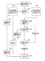
動作中、化学物質、例えば、岩塩は、混合器102の第1コンテナ104に堆積する。溶媒弁136が「オン」位置にあるとき、ポンプ124は、まず、「オフ」状態にある。HMI214において、オペレータは、所望の目標溶液濃度、製造される溶液の容量、および必要に応じて、完成品における添加物の比を入力する。この情報を入力する際、オペレータは、開始スイッチを作動し、開始スイッチは、PLCプログラムを動作モードに作動する。動作モードでは、溶媒は、弁136から混合器102、104へ流れ始める。混合器102の第1コンテナ104は、溶媒入口138、作動弁136、導管200、弁186、弁158、および導管176を介してスプレーヘッド178から溶媒を受ける。溶媒は、化学物質を溶解し、形成された溶液は格子142を通って混合器102の第2コンテナ106まで到達する。溶媒は、第3液面センサ122が、混合器102が液体で充填されていることを検出し、混合器102から液体が溢れないように溶媒弁136を「オフ」位置に作動するまで、スプレーヘッド178を通って混合器102に入り続ける。
During operation, chemicals, such as rock salt, accumulate in the
混合器102が溶媒を受ける間、第2液面センサ120は、十分な量の溶媒が混合器102内に存在するかどうかを検出する。十分な量の溶媒が混合器102中に存在するとき、ポンプ124は、「オン」位置に駆動される。ポンプ124は、バッチが完了するか、または第1液面センサ118が、液面が低いことを検出するまで、「オン」位置にラッチされる。
While the
ポンプ124は、混合器102の第2コンテナ106からの溶液を、第1吸引管164、導管188、弁154、導管、希釈入口146を通して、ポンプ124の吸引側入口まで移送する。ポンプ124は、45フィートのダイナミックヘッドを用いて、1時間当たり約5,000ガロンの溶液を注入するように構成され得る。
The
溶液センサ132は、ポンプ124によって混合器102、106から移送された溶液の導電率および温度を感知する。溶液センサ132は、溶液センサ132を横断して流れる溶液の電気抵抗を測定する。この測定は、溶液センサ132のプローブおよび導電率分析器によって行われ得る。電気抵抗は、溶液の温度と比較され、これら2つの変数は、等式化され、温度が補償された導電率測定値を形成する。この測定値は、化学濃度曲線に等式化され、この曲線は、温度が保証された重量百分率濃度として溶液の測定値を表す。温度が補償された導電率を濃度に関連づける濃度曲線は、溶液中のすべての化学物質に対して展開され得る。従って、例えば、塩水製造機では、塩化ナトリウム(および/または他の塩)濃度曲線が用いられる。
The
溶液が過剰濃縮されている場合、導電率分析器は、次に、PLC216と通信し、PLC216は希釈弁134を開いて、溶媒が混合器102、106中に存在する過剰に濃縮された溶液を目標濃度に希釈するようにする。希釈弁134が作動すると、溶媒入口138からの溶媒は、希釈弁134を通過して希釈入口146に達し、混合器102の第2コンテナ106からポンプ124へと通過する溶液と混合される。希釈弁134は、溶液が目標濃度に達するまで作動されたままである。過剰に濃縮された溶液は、分流弁130によってポンプ124から分流され、戻し管126を通過して、導管180、弁156および撹拌ノズル166を介して、混合器102の第1コンテナ104に達する。
If the solution is overconcentrated, the conductivity analyzer then communicates with the
溶液が濃縮不足である場合には、濃縮不足の溶液は、分流弁130によってポンプ124から分流され、戻し管126を通過して、弁156、導管180および撹拌ノズル166を介して混合器102の第1コンテナ104に達する。
If the solution is underconcentrated, the underconcentrated solution is diverted from the
溶液が目標濃度の公差レベル内である場合には、溶液は、分流弁130によってポンプ124から分流され、完成品管128を通過して、貯蔵タンク(図示せず)に達する。必要に応じて、溶液製造機の動作中にトラックに溶液が充填される場合、目標濃度の公差レベル内にある溶液は、トラック充填ホースを介してトラックに直接分流され得る。貯蔵タンクへ溶液を分流する際、充満している貯蔵タンクの充填を遮断するために電気プラグ配線ハーネス(remove till electric plug wiring harness)が設けられ得る。このようにして、感知デバイスは、貯蔵タンクの状態を感知するために設けられ得る。
If the solution is within the tolerance level of the target concentration, the solution is diverted from the
目標濃度の公差レベル内にある溶液が貯蔵タンクに送られるため、混合器102内では時間が経つにつれて液面が低下する。まず、液面センサ118は、混合器102内の水面が低いかどうかを検出し、溶液製造機100が動作モードである場合には、ポンプ124を「オフ」状態にする。あるいは、溶媒および化学物質が連続して溶液製造機に供給されてもよい。半連続実施形態では、溶液製造機100は、所望の濃度の溶液を連続して製造する。従って、溶液製造機100は、連続したバッチ処理用に構成され得る。連続したバッチ処理により、溶液製造機が動作している時間量につき溶液をより多く製造することができる。
Since the solution within the tolerance level of the target concentration is sent to the storage tank, the liquid level decreases in the
従って、溶液製造機の構成は、下方の流れを提供するように設計されている。混合器102の第1コンテナ104では、溶媒は、化学物質を通して下方に流れて溶液を形成する。上方への流れの設計も当該技術分野では周知であるが、そのような設計は、重力を打ち消すためのポンプも含むため、下方への流れの設計が支援される。言うまでもなく、本明細書に記載される態様は、上方および下方の両方の流れの設計を含む。
Accordingly, the solution maker configuration is designed to provide a downward flow. In the
溶液は格子142を通過し第2コンテナ106に達する。最大の濃度を有する溶液は、第2コンテナ106の底部に沈殿し、そこで溶液は取り除かれて処理される。
The solution passes through the
データログは、どれだけの溶液が製造されるか、および使用される成分(化学物質および溶媒)の量を記録するために溶液製造機によって生成され得る。 A data log can be generated by the solution maker to record how much solution is produced and the amount of components (chemicals and solvents) used.
図3、図5および図20はさらに、溶液製造機の簡単な洗浄態様を示す。 3, 5 and 20 further show a simple cleaning mode of the solution maker.
図3、図5および図21は、混合機102の第2コンテナ106の斜面および排水だめを示す。斜面のために、格子142を通過した沈殿物は、排水だめ出口108に隣接した領域内の第2部分の低部で収集される。任意の適切な数の斜面を用いてもよい。図示される実施形態では、第1斜面150、第2斜面152、および第3斜面202が設けられている。従って、格子142を通過する沈殿物は、第1斜面150、第2斜面152、および第3斜面202によって形成される領域内の、混合器102の第2コンテナ106の底部で収集される。排水だめ出口108は、上記のように、スプレーバー402およびノズル162を用いて、混合器102から沈殿物を流し出させる。
3, 5 and 21 show the slope and drainage of the
図2〜図4は、混合器102を示す。混合器102は、第1コンテナ104および第2コンテナ106を有する。ノズル162は、第2コンテナ106上に設けられている。ノズル162は、実質的に、第2コンテナ106に設けられた排水だめ出口108の方向に液体を噴霧する。1つの実施形態では、ノズル162によって噴霧される液体は水である。従って、液体は、ノズル162から放出され、排水だめ出口108に隣接して蓄積された沈殿物に方向づけられる。スプレーからの力によって、沈殿物は、排水だめ出口108を通過する。言うまでもなく、排水だめ出口を通して沈殿物を強制的に通過させる他の任意の適切な手段を用いてもよい。
2 to 4 show the
図19および図20にさらに示されるように、混合器102の第1コンテナ104は、スプレーヘッド178を含んでいてもよい。あるいは、第1コンテナ104は、複数のスプレーヘッドを含んでいてもよい。スプレーヘッド178は、溶媒弁136を介して溶媒入口138から溶媒を受ける。
As further shown in FIGS. 19 and 20, the
図6および図9は、混合器102の第2コンテナ106の対向する側に設けられた複数のスプレーバー402(一方の側のみが図示されている)を示す。スプレーバー402は、沈殿物を排水だめ出口108に強制的に方向づける液体を噴霧する。
6 and 9 show a plurality of spray bars 402 (only one side is shown) provided on the opposite side of the
上記のように、溶液製造機の使用中、沈殿物は、格子142を通って混合器102の第2コンテナ106に達し得る。第1傾斜面150および第2傾斜面152に沈殿した沈殿物は、第1傾斜面150および第2斜面152に沿って配置されたスプレーバー402を介して第2コンテナ106の底部に向かって下方に向けられる。スプレーバー402には、液体供給部138、導管200、水分注入口186、洗浄弁160、および導管174を介して、液体が供給される。第2コンテナ106の低部に設けられた沈殿物は、ノズル162を介して第2コンテナ106の排水だめ出口108から押出される。液体は、液体供給部138、導管200、水分注入口162、および導管172を介して、ノズル162に供給される。
As described above, during use of the solution maker, the precipitate can reach the
化学物質は、格子142によって第1コンテナ104内に支持されている。従って、沈殿物は、化学物質が混合器102の第1コンテナ内にあるとき、混合物102から流し出され得る。あるいは、沈殿物は、混合物102の第1コンテナ104内に化学物質が実質的に存在しないとき、混合器102から流し出され得る。
The chemical substance is supported in the
図12は、添加物が溶液に供給され得る溶液製造機用の制御パネルを示す。従って、溶液製造機は、添加物を所望の比で所望の溶液濃度で注入するために用いられ得る。例えば、溶液製造機が塩水を製造するために用いられるとき、塩水を比較的低温で作用させるか、または塩水の浸食性を低減する添加物が有益であり得る。 FIG. 12 shows a control panel for a solution maker where additives can be supplied to the solution. Thus, the solution maker can be used to inject the additive at the desired ratio and in the desired solution concentration. For example, when a solution maker is used to produce salt water, additives that operate the salt water at a relatively low temperature or reduce the erodibility of the salt water may be beneficial.
通常、塩水は、華氏約20度以上で使用される。添加物を塩水と混合することによって、塩水を用いるのに有効な温度は、華氏約0度まで低減され、それによって、比較的低温で雪および氷を解凍する溶液が提供される。塩水は、本来浸食性であり、塩水の浸食特性により、上路橋、車両および車道は浸食される。少なくとも1つの添加物を塩水に所定の比で混合することによって、塩水の浸食特性を低減し、塩水の凍結点を低下させると、環境にも有益である。一般に、これらの添加物は、コスト上、塩水溶液のコストと比較される。オプションとして、システムは、必要に応じて、所望量の添加物を溶液に添加する機能を有し、それによりコストを低減し、必要に応じて濃縮製品を製造することができる。 Usually, salt water is used at about 20 degrees Fahrenheit or higher. By mixing the additive with brine, the effective temperature for using the brine is reduced to about 0 degrees Fahrenheit, thereby providing a solution that thaws snow and ice at a relatively low temperature. Salt water is inherently erosive, and erosion characteristics of salt water cause erosion of upper road bridges, vehicles, and roadways. It is also beneficial to the environment to reduce the erosion characteristics of salt water and reduce the freezing point of salt water by mixing at least one additive with salt water in a predetermined ratio. In general, these additives are costly compared to the cost of an aqueous salt solution. Optionally, the system has the ability to add the desired amount of additives to the solution as needed, thereby reducing costs and producing a concentrated product as needed.
図12の実施形態を用いて、ユーザは、添加物が、HMI214を介して、最終製品が貯蔵される貯蔵タンクへと処理される全容量の所望の百分率を入力する。塩水が製造され、貯蔵タンクに分流されると、所定比の添加物は、添加物用の供給タンク(図示せず)に接続されたPLC216によって制御されるポンプ210を介して導管128に配置される。ポンプ210は、溶液を搬送する。流量計206は、PLC216と連通し、添加物の容量を測定する。流れを遮断するために作動される弁は、PLC216によって制御される。
Using the embodiment of FIG. 12, the user enters the desired percentage of the total volume at which the additive is processed via
従って、図12に示される実施形態では、溶液は、所望の濃度で製造され、溶液が保持タンクに搬送される際、溶液の容量に基づいた所望比の添加物は、溶液と混合され得る。この比は、必要に応じて、0%と100%との間であり得る。このように、溶液製造機は、塩水を製造し、任意の比の添加物を注入して溶液と混合する機能を有する。 Thus, in the embodiment shown in FIG. 12, the solution is manufactured at the desired concentration, and when the solution is transported to the holding tank, a desired ratio of additives based on the volume of the solution can be mixed with the solution. This ratio can be between 0% and 100%, as required. As described above, the solution manufacturing machine has a function of manufacturing salt water and injecting an additive in an arbitrary ratio to mix with the solution.
図16は、混合機102内のフロートアセンブリの斜視図である。
FIG. 16 is a perspective view of the float assembly in the
図17は、溶媒がスプレーヘッド178を介して溶液製造機の第1コンテナ104に添加される様子を示す。
FIG. 17 shows how the solvent is added to the
図18は、溶媒と、溶液製造機の第1コンテナ104内のバルク化学物質との混合を示す。
FIG. 18 shows the mixing of the solvent with the bulk chemical in the
図19は、バルク化学物質が第1コンテナ104に添加される前の、スプレーヘッド178が格子142上方にある第1コンテナ104を示す。
FIG. 19 shows the
図20は、溶媒がスプレーヘッド178からバルク材料上に噴霧されている第1コンテナ104の様子を示す。
FIG. 20 shows the
図21は、溶液が作成され、塩水出口弁154に流れる際の、第1斜面150および第3滑り面202を備えた第2コンテナ106の様子を示す。
FIG. 21 shows the
図22〜図25Bは、溶液製造機100およびさらなる構成要素に関連して用いられ得る様々なプロセスを示す。
22-25B illustrate various processes that may be used in connection with the
図22は、溶質と溶媒との混合物を作成するプロセスを示す。単一の溶質および単一の溶媒は、スラリーを製造するために頻繁に組合せられるが、本発明の態様は、それに限定されない。複数の溶質および溶媒からスラリーを製造することができる。例えば、溶媒2201および溶媒2202は、固体化学物質2203および固体化学物質2204と組合せられて、図22に示される新たなスラリー2206が製造される。この例示では、固体の化学物質が用いられるが、液体を用いることもできる。例えば、スラリー2206を製造するためにスラリー2205を溶媒2201および2202に添加することもできる。スラリー2205が溶媒に添加される唯一の化学物質である場合、溶液製造機は、希釈機械として機能する。
FIG. 22 shows the process of making a mixture of solute and solvent. Although a single solute and a single solvent are frequently combined to produce a slurry, embodiments of the invention are not so limited. Slurries can be made from multiple solutes and solvents. For example, solvent 2201 and solvent 2202 are combined with
上記のように、溶液製造機は、スラリー2206が所望の濃度を確実に上回るかまたは下回るようにするために用いることができる。ステップ2208では、スラリー2206の濃度は、屈折率、比重、および/または導電率の測定を含む任意の適切な手段でテストされる。上記のように、温度はまた、導電率/比重/屈折率を、スラリー内の化学物質の実際の濃度とさらに正確に関連づけるために測定され得る。例えば、状況によっては、濃度は、混合器102の位置でセンサによってテストされ得る。他の状況では、実際のセンサは、混合器102の物理位置から離れて設けられ得る。例えば、寒い気候では、混合器102が屋外にあるとき、センサは、センサおよび関連の処理/制御器具を保護するために、加熱された建物内に配置されてもよい。
As noted above, the solution maker can be used to ensure that the
スラリー2206が十分に濃縮されていない場合、溶質またはスラリー2203、2204および2205は、スラリー2206に添加される。スラリー2206が過剰に濃縮されている場合には、溶媒2201および/または2202が、ステップ2207において、スラリー2206に添加される。
If
ステップ2208で測定されるように、所望の濃度に一旦到達すると、図22において破線で示されるように、スラリー2206は、必要に応じて、1つまたはそれ以上の保持タンク2209および/または他のコンテナ2212に放出され得る。あるいは、プロセスは、混合器102が一杯になるまで、さらなるスラリー2206を製造し続けることができる。保持タンク2209および/または他のコンテナ2212に分流された溶液の量は、ステップ2210および2213で検出される。この量は、送達時間、使用される化学物質および溶媒、濃度設定などの製品に関する他の情報と共に、データログ2211に記録され得る。
Once the desired concentration has been reached, as measured in
データログ2211は、保持タンク2209および/または他のコンテナ2212の内容物の記録を保持するために用いられ得る。また、データログは、使用される未処理の溶質/溶媒/化学物質/スラリーの量を追跡するためにも用いられ得る。この情報は、置換化学物質および供給物のオーダー処理(order processing)を簡単するために用いられ得る。
Data log 2211 may be used to keep a record of the contents of holding
保持タンクおよび他のコンテナが図22に示されているが、溶液を連続プロセスの一部として放出してもよい。例えば、別個の数の保持タンクまたは他のコンテナを単に充填する代わりに、溶液を、製造される溶液を用いる一列の待トラックまたは他のプロセスなどの任意の受容器に、連続してまたはほぼ連続して供給してもよい。 Although a holding tank and other containers are shown in FIG. 22, the solution may be discharged as part of a continuous process. For example, instead of simply filling a separate number of holding tanks or other containers, the solution can be continuously or nearly continuously into any receiver, such as a row of waiting trucks or other processes that use the solution to be produced. May be supplied.
上記のように、他の容器へのスラリー2206の放出はオプションである。場合によっては、防寒モードで動作することが有利なこともある。このモードでは、混合器102は、屋外、または成分もしくは溶液が凍結可能な場所に配置される。制御パネルは、屋外または屋内に設けられ得る。防寒モードでは、スラリー2206は、溶媒または溶質が添加されない場合であっても、定期的にまたは連続して循環され得る。これにより、溶液が確実に均等に混合され、沈殿物の蓄積が防止され、スラリーまたは溶液の一部の凍結が防止され得る。連続混合により、導電率はさらに正確に測定できる。なぜなら、溶液の温度は、さらに均一に保たれ、導電率測定は、溶質の濃度および温度の両方に依存するからである。
As noted above, release of
≪添加物≫
図23は、製造される溶液に添加物を混合するための考えられる3つのプロセスを示す。図23Aでは、溶液の容量は、ステップ2301で検出される。この容量から、必要な添加物の容量は、ステップ2302で計算される。あるいは、まず、添加物の容量を決定し、溶液の必要な容量を、使用される添加物の容量から計算してもよい。溶液および添加物は、ステップ2303で組合せられる。
≪Additives≫
FIG. 23 shows three possible processes for mixing additives into the solution to be produced. In FIG. 23A, the volume of the solution is detected at
図23Bは、溶液への添加物の混合を自動化するために必要な論理を示す。まず、添加物と溶液との組合せの総容量(量)は、ステップ2304で決定される。この全容量(例えば、量)は、例えば、組合せを配置するコンテナの容量であり得る。このコンテナは、溶液または添加物が配置されるのと同じコンテナであり得るか、または第3コンテナ2307であってもよい。望ましい容量が、ステップ2308で決定されるように、コンテナ307または組合せが配置されるコンテナで得られる全空間よりも大きい場合には、警報2312が発せられる。混合が進行すれば、コンテナから液体が溢れてしまうであろう。あるいは、製造される組合せの容量は、所望の容量未満に調整され、警報を発するその他の理由が存在しない場合には、プロセスを進行してもよい。
FIG. 23B shows the logic necessary to automate the mixing of additives into the solution. First, the total volume (amount) of the combination of additive and solution is determined in
溶液と添加物との組合せの所望の容量2304は、必要な溶液の容量および必要な添加物の容量を計算するために用いられ得る。ステップ2309および2310で検出されるように、どちらかが十分でない場合には、警報2312を発しなければならない。所望の容量2304よりも少ない容量を製造することによって、必要に応じて、プロセスを進行させてもよい。
The desired
容量または添加物の容量を測定するステップ2309および2310は、圧力変換器を用いることによって実行され得る。変換器のセンサは、容器の底部に搭載される。圧力測定値は、変換器のセンサの上方の欄にある溶液または添加物の重量に比例する。容器に貯蔵された容量は、容器の寸法、および溶液または添加物の比重を用いて計算される。
上記のステップ2305、2306、2307、2308、2309、および2310のそれぞれは、オプションである。なぜなら、警報を発するには、ステップ2308、2309、および2310の任意の1つで十分だからである。あるいは、より少ないセンサまたはステップを用いて溶液製造システムを構築したい状況では、上記のステップのいくつかのステップのみを用いてもよい。警報が発せられる場合、プロセスは、他のステップの結果に関係なく、所望の容量2304を製造することができない。他方、ステップ2308で検出されるように、組合せに十分な空間があり、ステップ2309および2310で検出されるように、十分な溶液および添加物がある場合には、所望の容量の溶液および添加物の組合せがステップ2311で製造される。
Each of the
図23Cは、連続プロセスにおいて、添加物と溶液とを混合する論理を示す。図23Aおよび図23Bとは異なり、所望の容量は必要ない。その代わりに、溶液は、製造される最終量には関係なく放出される。溶液の流量は、ステップ2313で検出される。これは、多くの方法で成し遂げることができる。例えば、溶液の流れがタービンを回転させるレートを測定してもよい。他の技術では、時間間隔当たりの流量が検出される。この例では、1分当たり4ガロンの流量で15秒間弁が開口すると、1ガロンが分配される。
FIG. 23C shows the logic of mixing the additive and solution in a continuous process. Unlike FIGS. 23A and 23B, the desired capacity is not required. Instead, the solution is released regardless of the final volume produced. The solution flow rate is detected at
一旦溶液の流量が分かると、所望の混合物を作成するのに必要な添加物の流量は、ステップ2314で決定される。ステップ2315では、添加物の流量は、所望の混合物を製造するために、ステップ2314の計算に従って調節される。あるいは、添加物の流量を測定し、溶液の流量を調節してもよい。あるいは、最終の組合せの所望の流量を達成するために、添加物の流量と溶液の流量の両方を調節することもできる。当該技術分野で公知の比例積分微分(PID)回路は、流量が一定でない場合でも、添加物、溶液または両方の必要な流量を動的に計算するために用いられ得る。
Once the solution flow rate is known, the additive flow rate required to make the desired mixture is determined in
≪分配≫
図24は、ガソリンスタンドに持ってこられたドラムまたはトラックなどの容器に、溶液製造機によって製造された溶液を充填するための制御論理を示す。容器は、図22のステップ2208におけるように、溶液を製造するために用いられるタンクから充填されるか、または図22のステップ2209および2212におけるような保持タンクもしくは他のコンテナから充填され得る。充填コマンドを受けると、製品は、ステップ2401において容器に配置される。これは、ユーザがボタンを押すか、または充填されるトラックが重量反応性ローディング領域に引っ張られたときに起こり得る。ステップ2402は、容器に送達され、計算および測定される製品の流れを示す。図23を参照しながら記載されるように、分散される製品の量は、有用であると思われる製品に関する他の情報と共に、ステップ2403でデータログに記録され得る。例えば、トラックが充填されている場合、分散される製品の時間および量は、請求書をトラックの所有者に送るために用いられ得る。製品は、貯蔵容器が一杯になるまで(ステップ2405)、製品の注入を停止するコマンドを受けるまで(ステップ2406)、または供給不足もしくは何らかの誤動作のために製品がこれ以上送達されなくなるまで(ステップ2407)、ステップ2404におけるように、充填される容器まで流れる。上記のいずれかの事象が検出されると、注入は停止し、弁は閉じられる(ステップ2408)。
≪Distribution≫
FIG. 24 shows the control logic for filling a solution made by a solution maker into a container such as a drum or truck brought to a gas station. The container can be filled from the tank used to produce the solution, as in
図25Aは、本発明の他の態様の制御論理を示す。この制御論理は、所望の量の溶液、(溶液と添加物との)混合物、または両方を分配するために用いられ得る。ステップ2501では、製造される所望の量の溶液または混合物が決定される。所望の量は、人間のオペレータによって入力されるか、または充填される公知のサイズのコンテナなどの、所定の設定から得られ得る。分配される溶液または混合物を最終的に用いるプロセスの要件によって自動的に決定または定義されてもよい。
FIG. 25A shows the control logic of another aspect of the present invention. This control logic can be used to dispense a desired amount of solution, a mixture (solution and additive), or both. In
ステップ2502では、すでに利用可能な溶液または混合物の量が検出される。この量が分配される量と等しいか、またはこれよりも大きい場合、所望の量2501は、ステップ2506で分配される。ステップ2506で分配される容量(または量の他のインジケータ)は、ステップ2507でログまたはデータベースに記録される。このログは、データログ2211を参照して上述するように、機械動作の多数の態様を追跡するために用いられ、補助タスクを自動化するために用いられ得る。ステップ2508では、分配された量が確認される。これは、流量を測定するか、(いずれかが存在する場合には)溶液または混合物が分配される容器における溶液または混合物の容量を検出するか、溶液が分配される容器における溶液または混合物の容量を検出するか、または他の任意の適切な方法で成し遂げられ得る。所望の量が分配されていない場合には、分配および確認は続く。所望の量が分配されると、プロセスは停止される(ステップ2510)。
In
利用可能な溶液または混合物の量がステップ2502で検出されたとき、所望の量を分配するために利用可能な十分な溶液または混合物がないこともある。この場合、さらなる溶液を製造しなければならない。必要な溶液または混合物を製造するための材料が得られる場合(ステップ2504)、その溶液または混合物は、ステップ2505で作成され、ステップ2506で分配される。
When the amount of available solution or mixture is detected in
必要な量の溶液または混合物を製造するために得られる材料が十分ではない場合(ステップ2511)、ステップ2512で警報が発せられ、プロセスは停止する(ステップ2510)。
If the resulting material is not sufficient to produce the required amount of solution or mixture (step 2511), an alarm is raised at
ステップ2503(溶液/混合物が得られる)およびステップ2505(溶液/混合物を製造する)を同時に行うことも可能である。すなわち、予備量の溶液または混合物を維持することも可能である。予備量の溶液または混合物は、常に得られるか、または、通常の動作中に補充される。このように動作することで、所望量の入力と、その量の分配との間の遅延を低減し、効率を高めることができる。この場合、警報2512は、所望の量を分配することができないという警報であるが、所望の予備レベルの溶液が材料不足のため維持できないという警報でもあり得る。
It is also possible to perform step 2503 (to obtain a solution / mixture) and step 2505 (to make a solution / mixture) simultaneously. That is, it is possible to maintain a preliminary amount of solution or mixture. Preliminary amounts of solution or mixture are always obtained or replenished during normal operation. By operating in this way, the delay between the desired amount of input and the distribution of that amount can be reduced and efficiency can be increased. In this case,
最後に、上記のステップのいずれかが行われる間、機械は、ステップ2513においてそれ自体の機能を監視し、異常な動作だけでなく、材料の使用を検出することができる。欠陥が検出された場合(ステップ2514)、機械は、安全性および/または正確性を確保するために溶液の分配を停止し得る。限定しない実施例として、欠陥には、漏れまたは不適切な分配を示す予想外に高いもしくは低いレベルの溶液またはソース材料が検出されることが含まれる。
Finally, while any of the above steps are performed, the machine can monitor its own function in
所望される溶液または混合物を製造して分配するステップ2505は、図25Aで示される全プロセスを含み得る。これは、所望の量の混合物がステップ2501で製造される場合に起こり得る。混合物は、添加物と溶液との組合せである。ステップ2505では、混合物は、溶液と添加物とを組合せることによって製造される。添加物と混合するのに必要な溶液の量は、所望の量2501と考えられる。従って、溶液を分配するプロセスは、混合物を分配するプロセスのステップ2505に含まれ得る。
図25Bは、図25Aと同様であるが、溶液または混合物を予め製造して得る必要がないため、このようなステップが提供される必要がないことを示す。本発明のこの態様では、溶液または混合物を製造するのに必要な材料の量は、所望の量が入力された(ステップ2501)後、ステップ2515で確認される。所望の量を製造するのに十分な材料が得られる場合(ステップ2517)、その量は製造され(ステップ2505)、分配される(ステップ2506)。十分な材料が得られない場合(ステップ2516)、警報が発せられ(ステップ2512)、プロセスは停止する。図25Bの設計は、溶液または混合物を予め製造することが、例えば、空間の制約のためにさらに困難であるかコストがかかる状況下で有利である。
FIG. 25B is similar to FIG. 25A, but shows that such a step need not be provided because the solution or mixture need not be pre-manufactured and obtained. In this aspect of the invention, the amount of material needed to produce the solution or mixture is ascertained in
最後に、本発明のタンクは、化学物質の混合を調節する制御システムと共に用いられるが、タンクは、制御システムから分離して用いられ、制御システムは、タンクから分離して、または異なるタンクに関連して、使用され得る。 Finally, the tank of the present invention is used with a control system that regulates the mixing of chemicals, but the tank is used separately from the control system, and the control system is separate from the tank or associated with a different tank. And can be used.
≪化学物質、溶液、および溶媒≫
様々な化学物質、溶液および溶媒が、本発明の態様を用いて、使用および作成され得る。例として、酢酸カルシウムマグネシウム、塩化カルシウム、塩化マグネシウム、酢酸カリウム、ギ酸カリウム、ギ酸ナトリウム、酢酸マグネシウム、燐酸二アンモニウム、燐酸モノアンモニウム、尿素、エチルグリコール、フェニレングリコール、および他の化学物質が挙げられる。
≪Chemicals, solutions, and solvents≫
A variety of chemicals, solutions and solvents can be used and created using embodiments of the present invention. Examples include calcium magnesium acetate, calcium chloride, magnesium chloride, potassium acetate, potassium formate, sodium formate, magnesium acetate, diammonium phosphate, monoammonium phosphate, urea, ethyl glycol, phenylene glycol, and other chemicals.
≪改変≫
様々な態様において、1つまたはそれ以上の構造、システム、方法等は、他の構造、システム、方法等と組合せて用いられてもよい。さらに、溶液製造機の構造は、以下のようなさらなる改変を含んでいてもよい。まず、例えば、溶液の1つまたはそれ以上の成分は、非プラスチック材料で形成され得る。例えば、格子142は、少なくとも部分的または全体的に、非プラスチック材料で形成され得る。同様に、第1コンテナ104および第2コンテナ106の少なくとも1つは、非プラスチック材料の少なくとも一部で構築され得る。プラスチックは、他の材料に対して多数の利点を有する。それにもかかわらず、プラスチック材料は、様々な状況において、他の材料ほど有益ではない。例えば、プラスチック材料は、気温が低いと、または様々な化学物質もしくは紫外線に曝されると、脆くなることがある。この点、ステンレス鋼、アルミニウム、または他の金属は、様々な環境で用いるのに有益であり得る。1つの例では、ステンレス鋼は、他の材料が浸食され得る場合に高い浸食耐性を有する点で有益である。あるいは、溶液製造機100の1つまたはそれ以上の構成要素、および/または関連ラインの可撓性、弾性および動きを向上させるために、プラスチック材料の代わりにゴムを用いてもよい。さらに、コンクリートまたは他の材料を用いてもよい。なぜなら、コンクリートは耐久性があり、コスト効率が高いからである。
≪Modification≫
In various aspects, one or more structures, systems, methods, etc. may be used in combination with other structures, systems, methods, etc. Furthermore, the structure of the solution maker may include further modifications as follows. First, for example, one or more components of the solution can be formed of a non-plastic material. For example, the
第2に、溶液製造機100への水分注入口は、単純な入口弁であっても、溶媒供給スプレーパターンをシフトし、化学物質を溶液にさらに完全に溶解させる能動デバイスであってもよい。例えば、入口弁は、回転スプレーパターン、振動スプレーパターン、および格子142上の不要な化学物質の蓄積を防止する他の任意のスプレーパターンを有し得る。同様に、第2コンテナ106用の入口弁は、スプレーパターンを変更する1つまたはそれ以上の弁と置き換えられてもよい。
Secondly, the water inlet to the
第3に、混合器102を除去し、混合タンクを用いずに様々な化学物質および溶媒を混合させる混合環境を提供する流れ制御および混合弁に置き換えてもよい。
Third, the
第4に、溶液製造機100は、図26に示されるように、改変された構造を有し得る。図26は、第1部分2601および第2部分2602を示す。浸透性格子の代わりに、第1部分2601の底部は、不浸透性層2603である。溶媒2609は、ポート2610を通って第1部分2601に入る。次に、溶媒2611は、容量2611として示されるように、部分2601を充填する。ポート2610は、部分2601の(頂部壁および底部壁を含む)いずれかの側に設けられ得る。
Fourth, the
部分2602の頂部は浸透性格子2604である。溶媒2609に溶解される化学物質は、経路2605およびオプションの2607を介して、矢印2606および2608の方向に1つまたはそれ以上の側(または頂部導管(図示せず))を通って添加され得る。溶解される化学物質は、化学物質2612として示されるように、格子2604上に蓄積される。次に、溶媒2611は、第1部分2601から2602へと導管2614をたどる。次に、溶媒2611は、格子2604を通して上方に方向づけられるか、または格子2604と不浸透性層2603との間に直接噴霧され得る。化学物質2612が溶媒2611に溶解しながら、混合物は、溶液2616で示されるように、格子2604を通過する。次に、溶液2616は、本明細書に記載されるようにさらに処理され得る。
The top of
言うまでもなく、化学物質2612は、固体材料、液体、またはスラリーであり得る。例えば、化学物質2612は、化学物質2612が溶解する水または他の化合物などの溶媒2611と混合される、塩、食塩水、または(エチレングリコールもしくは肥料などの)液体化学物質であり得る。
Of course, the
第5に、混合システム102の更なる態様は、保持タンクが存在しないように改変されてもよい。図27は、保持タンクを有さない混合システム102を示す。第1供給ライン2701は、濃縮された溶液2703を供給する。第2供給ライン2702は、溶媒2704を供給する。濃縮された溶液2703および溶媒2704は、位置2705で混合される。濃度の検出は、位置2706で行われる。濃度の検出2706の結果は、所望の濃度の混合溶液が分流ポート2708を通って供給され、2709で出されるように分流加減器2707を制御する。高すぎる濃度のものは、分流ポート2710を通って供給され、オプションの制御弁2711を用いて、濃縮された供給材料2703に戻される。非常に低すぎる濃度のものは、分流ポート2712を通って供給され、オプションの制御弁2713を用いて濃縮された供給材料2704に戻される。混合物の濃度が非常に高すぎる場合、その混合物を濃縮された溶液2703に供給すると、予め添加された溶媒のために、点2705で混合物の濃度が低減される。その結果、濃度は、点2705において減少する。同様に、混合物の濃度が非常に低すぎる場合、混合物を溶媒2704に供給することによって、あらかじめ添加された濃縮物2703のために、点2705で混合物の濃度が増加される。その結果、混合物の濃度は、点2705で増加する。
Fifth, further aspects of the
実施形態および応用
本発明の態様は、以下の実施形態に分類される様々な応用で用いられ得る。
Embodiments and Applications Aspects of the invention can be used in a variety of applications that fall into the following embodiments.
第1の実施形態では、本発明の態様は、防氷用の塩水混合などの浸食環境において用いられ得る。防氷用に用いられる塩水は、非常に浸食性が高い。塩水と接触する精密器具の数を最小限に抑えることは重要である。例えば、溶液中のスピニング流量計を増加させることにより、流量計の連続した欠陥による、深刻なメンテナンス問題が発生し得る。腐食性環境用の流量計を用いてもよいが、流量計のコストは高く、それによって、溶液製造機全体はさらに高価になる。しかし、このタイプの流量計を用いる1つの利点は、それを流れて通過する材料の非常に正確な測定を提供することができることである。 In the first embodiment, aspects of the present invention may be used in an erosive environment such as a salt mix for anti-icing. Salt water used for anti-icing is very erosive. It is important to minimize the number of precision instruments that come into contact with salt water. For example, increasing the spinning flow meter in solution can cause serious maintenance problems due to continuous defects in the flow meter. Although a flow meter for corrosive environments may be used, the cost of the flow meter is high, which makes the entire solution maker more expensive. However, one advantage of using this type of flow meter is that it can provide a very accurate measurement of the material flowing through it.
第2の実施形態では、本発明の態様は、腐食性環境の少ない他の塩水づけ産業において用いられ得る。例えば、本発明の態様は、チーズ、飲料、または肉処理産業において用いられ得る。ここで、食物は、防氷環境の塩レベルよりも低い塩レベルを有する塩水溶液に浸されてもよい。 In a second embodiment, aspects of the present invention can be used in other salting industries with less corrosive environments. For example, aspects of the invention can be used in the cheese, beverage, or meat processing industries. Here, the food may be soaked in an aqueous salt solution having a salt level lower than that of the anti-icing environment.
第3の実施形態では、本発明の態様は、大量の水または他の液体化学物質が次の処理に提供されるかまたは使用される前に混合される必要がある産業用の水供給環境で用いられてもよい。例えば、病院、処理プラント、エネルギー生成プラント等は、大量の処理水または他の材料を必要とし得る。本発明の態様は、これらの応用のために溶液の混合を助けるため用いられ得る。 In a third embodiment, aspects of the invention may be used in industrial water supply environments where large quantities of water or other liquid chemicals need to be mixed before being provided or used for subsequent processing. May be used. For example, hospitals, treatment plants, energy generation plants, etc. may require large amounts of treated water or other materials. Embodiments of the present invention can be used to assist in mixing solutions for these applications.
第4の実施形態では、本発明の態様は、限定はされないが、様々な油、ウォーター切断(water cutting)またはサンドブラストで用いられる溶液、混合肥料の製造、製粉等を含む他の化学物質またはスラリーを混合するために用いられ得る。 In a fourth embodiment, aspects of the invention include, but are not limited to, various chemicals or slurries including various oils, solutions used in water cutting or sand blasting, mixed fertilizer manufacturing, milling, etc. Can be used to mix.
本発明は、実施形態を参照して記載されているが、当業者は、本発明の趣旨および範囲を逸脱せずに、形式および詳細が変更され得ることを認識されたい。 Although the present invention has been described with reference to embodiments, those skilled in the art will recognize that the format and details may be changed without departing from the spirit and scope of the invention.
Claims (26)
前記化学物質が供給されるとともに前記溶媒を受ける第1位置(104)と、
前記第1位置(104)を通過した前記溶媒と前記化学物質の溶液を受ける第2位置(106)と、
前記第2位置(106)から流出した前記溶液の濃度を検出し信号を出力する濃度センサ(132)と、
前記信号に基づいて前記溶液の濃度を検出するプロセッサ(216)と、
前記溶液の濃度が所望の濃度未満になると、前記溶液を前記第1位置(104)に戻す第1戻し経路(126, 156, 180, 166)と、
前記溶液の濃度が所望の濃度を上回ると、前記溶液を前記第2位置(106)に戻し、さらなる溶媒を前記溶液に追加するための入口(146)を含む第2戻し経路(126, 156, 180, 166, 142)と、
前記所望の濃度を有する前記溶液を放出する出口(128)とを備えた溶液製造システム。A solution manufacturing system combining a solvent and a chemical substance,
A first location (104) to which the chemical is supplied and to receive the solvent;
A second position (106) for receiving the solvent and the chemical solution that has passed through the first position (104);
A concentration sensor (132) for detecting the concentration of the solution flowing out from the second position (106) and outputting a signal;
A processor (216) for detecting the concentration of the solution based on the signal;
A first return path (126, 156, 180, 166) for returning the solution to the first position (104) when the concentration of the solution is less than a desired concentration;
When the concentration of the solution exceeds a desired concentration, a second return path (126, 156, including an inlet (146) for returning the solution to the second position (106) and adding additional solvent to the solution. 180, 166, 142)
A solution production system comprising an outlet (128) for discharging the solution having the desired concentration.
前記添加物が前記溶液と混合される混合位置と、
前記添加物および前記溶液が所望の濃度および所望の容量の一方になるように混合され得るかどうかを検出し、前記添加物と前記溶液との混合を制御して前記所望の濃度および前記所望の容量の少なくとも1方を達成するプロセッサ(216)とを備えた請求項1に記載の溶液製造システム。An additive container for holding the additive;
A mixing position where the additive is mixed with the solution;
Detecting whether the additive and the solution can be mixed to one of a desired concentration and a desired volume, and controlling the mixing of the additive with the solution to control the desired concentration and the desired The solution manufacturing system according to claim 1, further comprising a processor (216) that achieves at least one of the capacities.
前記プロセッサ(216)は、前記信号を用いて前記添加物コンテナ内の添加物の容量を検出する請求項5に記載の溶液製造システム。A sensor provided in the additive container for outputting a signal;
The solution manufacturing system according to claim 5, wherein the processor (216) detects a volume of an additive in the additive container using the signal.
前記プロセッサ(216)は、前記信号を用いて前記溶液コンテナ内の前記溶液の容量を検出する請求項5に記載の溶液製造システム。A sensor provided in a solution container that holds the solution and outputs a signal;
The solution manufacturing system according to claim 5, wherein the processor (216) detects a volume of the solution in the solution container using the signal.
前記プロセッサ(216)は、前記信号を用いて前記溶液と前記添加物から形成された混合物を保持するための前記出力コンテナ内における利用可能な容量を検出する請求項5に記載の溶液製造システム。A sensor provided in the output container for outputting a signal;
The solution manufacturing system of claim 5, wherein the processor (216) uses the signal to detect an available volume in the output container for holding a mixture formed from the solution and the additive.
前記プロセッサ(216)は、前記検出のために前記信号を用いる請求項5に記載の溶液製造システム。A sensor for outputting a signal to the processor (216);
The solution manufacturing system according to claim 5, wherein the processor (216) uses the signal for the detection.
前記混合位置(104, 106)から流出した前記溶液を前記混合位置(104, 106)に戻す第1経路(126, 156, 180, 166)と、
前記混合位置(104, 106)から流出した前記溶液および追加溶媒を前記混合位置(104, 106)に戻す第2経路(146, 212, 126, 156, 180, 166)と、
添加物と溶液との混合物の所望の濃度を得ることが可能であるかどうかを検出するセンサ(204, 206)を有する添加物混合位置と、
前記添加物混合位置から前記添加物と溶液の所望の濃度の混合物を放出する出力部(128)とを備えた添加物添加システム。A mixing position (104, 106) in which at least one solute is dissolved in at least one solvent;
A first path (126, 156, 180, 166) for returning the solution flowing out from the mixing position (104, 106) to the mixing position (104, 106);
A second path (146, 212, 126, 156, 180, 166) for returning the solution and additional solvent flowing out of the mixing position (104, 106) to the mixing position (104, 106);
An additive mixing position having sensors (204, 206) for detecting whether it is possible to obtain a desired concentration of the additive-solution mixture;
An additive addition system comprising an output (128) for discharging a mixture of the additive and a desired concentration of the solution from the additive mixing position.
Applications Claiming Priority (3)
| Application Number | Priority Date | Filing Date | Title |
|---|---|---|---|
| US11/190,395 US7810987B2 (en) | 2005-07-27 | 2005-07-27 | Automated solution maker apparatus |
| US11/190,395 | 2005-07-27 | ||
| PCT/US2006/028951 WO2007016135A2 (en) | 2005-07-27 | 2006-07-27 | Solution making system and method |
Related Child Applications (1)
| Application Number | Title | Priority Date | Filing Date |
|---|---|---|---|
| JP2012153786A Division JP5735460B2 (en) | 2005-07-27 | 2012-07-09 | Solution manufacturing system and method |
Publications (2)
| Publication Number | Publication Date |
|---|---|
| JP2009502482A JP2009502482A (en) | 2009-01-29 |
| JP5089587B2 true JP5089587B2 (en) | 2012-12-05 |
Family
ID=37421098
Family Applications (2)
| Application Number | Title | Priority Date | Filing Date |
|---|---|---|---|
| JP2008524090A Active JP5089587B2 (en) | 2005-07-27 | 2006-07-27 | Solution manufacturing system and method |
| JP2012153786A Active JP5735460B2 (en) | 2005-07-27 | 2012-07-09 | Solution manufacturing system and method |
Family Applications After (1)
| Application Number | Title | Priority Date | Filing Date |
|---|---|---|---|
| JP2012153786A Active JP5735460B2 (en) | 2005-07-27 | 2012-07-09 | Solution manufacturing system and method |
Country Status (14)
| Country | Link |
|---|---|
| US (4) | US7810987B2 (en) |
| EP (3) | EP1912727B1 (en) |
| JP (2) | JP5089587B2 (en) |
| KR (1) | KR101313457B1 (en) |
| CN (1) | CN101262933B (en) |
| AT (1) | ATE500882T1 (en) |
| CA (2) | CA2829299C (en) |
| DE (1) | DE602006020584D1 (en) |
| DK (1) | DK1912727T3 (en) |
| HK (2) | HK1119615A1 (en) |
| PL (1) | PL1912727T3 (en) |
| RU (1) | RU2435632C2 (en) |
| SI (1) | SI1912727T1 (en) |
| WO (1) | WO2007016135A2 (en) |
Cited By (1)
| Publication number | Priority date | Publication date | Assignee | Title |
|---|---|---|---|---|
| US11610467B2 (en) | 2020-10-08 | 2023-03-21 | Ecolab Usa Inc. | System and technique for detecting cleaning chemical usage to control cleaning efficacy |
Families Citing this family (40)
| Publication number | Priority date | Publication date | Assignee | Title |
|---|---|---|---|---|
| US20090092001A1 (en) | 2005-07-27 | 2009-04-09 | Clay Hildreth | Solution making system and method |
| US7810987B2 (en) * | 2005-07-27 | 2010-10-12 | Cargill, Incorporated | Automated solution maker apparatus |
| NL2001432C2 (en) * | 2008-04-02 | 2009-10-05 | Schuitemaker Mach Bv | Method, filling station and storage container for providing spreading material, method for distributing spreading material and slurry-containing slurry. |
| DE102009038481B4 (en) * | 2009-08-21 | 2011-09-01 | Leica Biosystems Nussloch Gmbh | Method for operating a tissue processor |
| US8602069B2 (en) * | 2010-05-20 | 2013-12-10 | Ecolab Usa Inc. | Solid chemical product dilution control |
| GB201101075D0 (en) | 2011-01-21 | 2011-03-09 | Labminds Ltd | Automated solution dispenser |
| US10544340B2 (en) | 2011-10-20 | 2020-01-28 | Henderson Products, Inc. | Brine generation system |
| US10766010B2 (en) | 2011-10-20 | 2020-09-08 | Henderson Products, Inc. | High throughput brine generating system |
| JP5894424B2 (en) * | 2011-12-09 | 2016-03-30 | 東海染工株式会社 | Component concentration monitoring method and component concentration monitoring apparatus using this method |
| DK2874736T3 (en) | 2012-07-18 | 2023-05-22 | Accroma Labtec Ltd | AUTOMATED SOLUTION DISPENSER |
| WO2014018896A1 (en) | 2012-07-27 | 2014-01-30 | Deka Products Limited Partnership | Control of conductivity in product water outlet for evaporation apparatus |
| US9096979B2 (en) * | 2012-09-27 | 2015-08-04 | Louis Berkman Company | Software application that allows a user to utilize a mobile device to control frozen precipitation treatment systems |
| CN105431732B8 (en) * | 2013-05-31 | 2019-09-03 | 雀巢产品有限公司 | For detecting water/Product Interface system and method during food process |
| WO2015023684A2 (en) * | 2013-08-12 | 2015-02-19 | Barrineau Wade Iii | Automated mixing system |
| CN103953165B (en) * | 2014-05-20 | 2016-04-13 | 西华大学 | Light section steel structure roofing green intelligent snow removal system |
| WO2016050566A1 (en) | 2014-09-29 | 2016-04-07 | Ge Healthcare Bio-Sciences Ab | Method for predicting the solubility of a buffer |
| CN107835712B (en) | 2015-02-06 | 2021-09-10 | 莱伯曼兹有限公司 | Automated solution dispenser |
| AU2016224136B2 (en) * | 2015-02-24 | 2019-12-12 | Liquitab Systems Limited | Improved apparatus for disintegration of a solid and method |
| CA2990017A1 (en) * | 2015-06-30 | 2017-01-05 | Cargill, Incorporated | Apparatus for making a solution, and related methods |
| EP3371273A4 (en) * | 2015-11-03 | 2019-06-05 | Cargill, Incorporated | System and method for producing temperature stable chemical solutions |
| US10253230B1 (en) * | 2015-12-17 | 2019-04-09 | City of Lincoln, Nebraska | Method of producing, system for producing, and composition of deicing brines without crystallization |
| JP6942918B2 (en) * | 2016-04-13 | 2021-09-29 | コブハム・ミッション・システムズ・ダベンポート・エルエスエス・インコーポレイテッド | Onboard Inert Gas Generation System Predictive Health Monitoring |
| CN106512845A (en) * | 2016-10-25 | 2017-03-22 | 北京小米移动软件有限公司 | Method and device for preparation of solution |
| EP3600637A1 (en) * | 2017-03-22 | 2020-02-05 | Isopure, Corp. | Acid mixing system and method |
| CA3068618A1 (en) * | 2017-06-30 | 2019-01-03 | FUJIFILM Irvine Scientific, Inc. | Automated method and apparatus for preparing bioprocess solutions |
| CN108126549A (en) * | 2017-12-25 | 2018-06-08 | 沈阳创新航空科技有限公司 | The compounding system and technique of No. 65 coolant pollution grades |
| CN109984884A (en) * | 2017-12-29 | 2019-07-09 | 北京紫牛生活科技有限公司 | A kind of warning device preparing nanometer silver antimicrobial liquid absorbent wick |
| AU2019222671A1 (en) * | 2018-02-13 | 2020-08-20 | Ecolab Usa Inc. | System and method for dissolving solid chemicals and generating liquid solutions |
| CN108355531B (en) * | 2018-03-16 | 2020-07-28 | 溢通环保科技(莆田)有限公司 | Automobile-used urea solution preparation facilities |
| CN108479490B (en) * | 2018-03-16 | 2020-07-28 | 溢通环保科技(莆田)有限公司 | Production control method of urea solution for vehicles |
| US10421048B1 (en) * | 2019-04-24 | 2019-09-24 | Duo Lift Manufacturing Co., Inc. | Salt brine production system |
| CN110095403A (en) * | 2019-05-31 | 2019-08-06 | 中国电力科学研究院有限公司 | A kind of method and system controlling dry-type transformer environmental test electrical conductivity of solution |
| JP7180549B2 (en) | 2019-06-19 | 2022-11-30 | 株式会社デンソー | Fluid injection device |
| CN110652896A (en) * | 2019-09-29 | 2020-01-07 | 珠海格力智能装备有限公司 | Method and device for detecting solution concentration and automobile urea intelligent machine |
| NL2023979B1 (en) * | 2019-10-08 | 2021-04-13 | R&R Mechatronics Int B V | Diluting device |
| CN110923798B (en) * | 2019-11-26 | 2020-12-25 | 王勇 | Liquid supply device for electrochemical polishing |
| CN111589312A (en) * | 2020-06-01 | 2020-08-28 | 珠海格力智能装备有限公司 | Method and device for dissolving urea, storage medium, processor and stirring system |
| US11796437B2 (en) | 2020-06-30 | 2023-10-24 | Brine Masters, LLC | Measuring density via pressure sensor in a conduit |
| CN112717825A (en) * | 2020-12-15 | 2021-04-30 | 上海奥栋机电有限公司 | Propylene glycol liquid supplementing device, control method and device thereof, and storage medium |
| CN114910622B (en) * | 2022-06-22 | 2023-08-08 | 清华苏州环境创新研究院 | Calibration device and method for water quality monitoring Internet of things sensor |
Family Cites Families (35)
| Publication number | Priority date | Publication date | Assignee | Title |
|---|---|---|---|---|
| US3595438A (en) * | 1969-01-06 | 1971-07-27 | Economics Lab | Automatic detergent dispenser system |
| US4026801A (en) * | 1976-01-08 | 1977-05-31 | Duratainer Inc. | Combination water softener cabinet and brine receptacle |
| US4247298A (en) * | 1979-03-29 | 1981-01-27 | The Regents Of The University Of Minnesota | Drug dissolution with a cascade barrier bed |
| JPS57159529A (en) | 1981-03-26 | 1982-10-01 | Terumo Corp | Apparatus for continuously dissolving sodium bicarbonate |
| FR2517984A1 (en) | 1981-12-14 | 1983-06-17 | Lebon Et Cie Sarl | Brine prodn. process - circulates water upwards through bed of salt crystals and stores brine in downstream tank |
| JPS6058231A (en) * | 1983-09-09 | 1985-04-04 | Tapuroge Japan Kk | Dissolving tank and continuous supply apparatus of chemical solution |
| JPS60227822A (en) | 1984-04-26 | 1985-11-13 | Hitachi Plant Eng & Constr Co Ltd | Liquid medicine preparating apparatus |
| US5137694A (en) * | 1985-05-08 | 1992-08-11 | Ecolab Inc. | Industrial solid detergent dispenser and cleaning system |
| JPH01159040A (en) * | 1987-08-21 | 1989-06-22 | Fuji Photo Film Co Ltd | Method and apparatus for measuring, mixing and distributing liquid |
| US4976377A (en) | 1987-08-21 | 1990-12-11 | Fuji Photo Film Co., Ltd. | Liquid and powder measuring apparatus |
| JPH0233538A (en) | 1988-07-21 | 1990-02-02 | Taikisha Ltd | Radiation type air conditioner |
| US4863277A (en) * | 1988-12-22 | 1989-09-05 | Vigoro Industries, Inc. | Automated batch blending system for liquid fertilizer |
| US5163010A (en) | 1990-02-22 | 1992-11-10 | Revlon Consumer Products Corporation | Formulating device for cosmetically functional cosmetic products |
| JPH0527351A (en) | 1991-07-22 | 1993-02-05 | Konica Corp | Method for adjusting photographic additive |
| JP3457708B2 (en) | 1993-07-06 | 2003-10-20 | 三菱重工業株式会社 | Granular or powdery water-soluble solid aqueous solution automatic preparation equipment |
| US5590960A (en) * | 1993-11-04 | 1997-01-07 | E. I. Du Pont De Nemours And Company | One tank paint makeup process using a recirculation loop with liquid injection |
| JPH0871389A (en) | 1994-09-07 | 1996-03-19 | Tokyo Ohka Kogyo Co Ltd | Preparation of developing solution |
| JP2883584B2 (en) * | 1995-07-17 | 1999-04-19 | アロカ株式会社 | Ultrasonic image processing apparatus and method |
| JPH0933538A (en) * | 1995-07-19 | 1997-02-07 | Toa Medical Electronics Co Ltd | Method and unit for preparing reagent |
| US5647391A (en) * | 1996-04-11 | 1997-07-15 | Diversey Corporation | Sensing arrangement for sensing the addition of reactants to a solution |
| US6048391A (en) * | 1996-09-27 | 2000-04-11 | Serco Holland | Means for and methods of preparing a glue for corrugated board |
| JP3741811B2 (en) * | 1996-12-25 | 2006-02-01 | 三菱化学エンジニアリング株式会社 | Method and apparatus for diluting alkaline developer stock solution |
| JP3578888B2 (en) * | 1997-04-30 | 2004-10-20 | アマノ株式会社 | Salt water generator for electrolyzed water generator |
| US6049391A (en) * | 1998-01-08 | 2000-04-11 | Xerox Corporation | System for printing with ordered stock |
| US6331255B1 (en) * | 1999-07-09 | 2001-12-18 | Donald B. Peddicord | Accessible well for brine tank |
| JP2001232162A (en) * | 2000-02-22 | 2001-08-28 | Fuji Electric Co Ltd | Device for preparing solution of common salt |
| JP4648513B2 (en) * | 2000-03-15 | 2011-03-09 | 関東化学株式会社 | Concentration detection method, concentration detection device, and drug dilution blending device |
| US6439252B1 (en) * | 2001-04-26 | 2002-08-27 | Varitech Industries, Inc. | Liquid de-icer production apparatus and method |
| US6451270B1 (en) * | 2001-05-25 | 2002-09-17 | Sprayer Specialties, Inc. | Brine maker with removable hopper |
| US6845298B2 (en) | 2001-08-31 | 2005-01-18 | Force Flow | Diluting system and method |
| US6736153B1 (en) * | 2001-09-24 | 2004-05-18 | H.Y.O., Inc. | Brining system, method, and apparatus |
| US7186390B1 (en) * | 2001-10-04 | 2007-03-06 | Duolift Mfg. Co., Inc. | Brine maker |
| US20040004903A1 (en) * | 2002-07-03 | 2004-01-08 | Johnsondiversey, Inc. | Apparatus and method of mixing and dispensing a powder |
| JP4514431B2 (en) | 2003-10-17 | 2010-07-28 | Udトラックス株式会社 | Urea aqueous solution manufacturing equipment |
| US7810987B2 (en) | 2005-07-27 | 2010-10-12 | Cargill, Incorporated | Automated solution maker apparatus |
-
2005
- 2005-07-27 US US11/190,395 patent/US7810987B2/en active Active
-
2006
- 2006-07-27 EP EP20060788505 patent/EP1912727B1/en active Active
- 2006-07-27 EP EP20080019201 patent/EP2018903A3/en not_active Withdrawn
- 2006-07-27 JP JP2008524090A patent/JP5089587B2/en active Active
- 2006-07-27 DK DK06788505T patent/DK1912727T3/en active
- 2006-07-27 CA CA2829299A patent/CA2829299C/en active Active
- 2006-07-27 PL PL06788505T patent/PL1912727T3/en unknown
- 2006-07-27 CA CA 2616972 patent/CA2616972C/en active Active
- 2006-07-27 CN CN2006800322615A patent/CN101262933B/en active Active
- 2006-07-27 KR KR1020087004597A patent/KR101313457B1/en active IP Right Grant
- 2006-07-27 EP EP20080019200 patent/EP2018902A3/en not_active Withdrawn
- 2006-07-27 WO PCT/US2006/028951 patent/WO2007016135A2/en active Application Filing
- 2006-07-27 SI SI200631027T patent/SI1912727T1/en unknown
- 2006-07-27 DE DE200660020584 patent/DE602006020584D1/en active Active
- 2006-07-27 AT AT06788505T patent/ATE500882T1/en not_active IP Right Cessation
- 2006-07-27 RU RU2008107333A patent/RU2435632C2/en not_active Application Discontinuation
-
2008
- 2008-10-20 HK HK08111568A patent/HK1119615A1/en not_active IP Right Cessation
-
2009
- 2009-01-06 HK HK09100081A patent/HK1123007A1/en not_active IP Right Cessation
- 2009-02-18 US US12/388,287 patent/US8382364B2/en active Active
-
2010
- 2010-08-31 US US12/872,704 patent/US8251569B2/en active Active
-
2012
- 2012-06-29 US US13/537,342 patent/US8870444B2/en active Active
- 2012-07-09 JP JP2012153786A patent/JP5735460B2/en active Active
Cited By (1)
| Publication number | Priority date | Publication date | Assignee | Title |
|---|---|---|---|---|
| US11610467B2 (en) | 2020-10-08 | 2023-03-21 | Ecolab Usa Inc. | System and technique for detecting cleaning chemical usage to control cleaning efficacy |
Also Published As
Similar Documents
| Publication | Publication Date | Title |
|---|---|---|
| JP5089587B2 (en) | Solution manufacturing system and method | |
| US10376854B2 (en) | Solution making system and method | |
| JP4130588B2 (en) | Duplex solid chemical supply system | |
| US11643341B2 (en) | Antimicrobial capture system with carbon container | |
| US20140269153A1 (en) | Chemical solution mixing and dispensing apparatus | |
| CA2969734C (en) | Device and method for pastillating a flowable product | |
| US6439252B1 (en) | Liquid de-icer production apparatus and method | |
| FI125413B (en) | Apparatus and method for dispensing washing solution for introduction into washing device, car wash and program part | |
| KR101412526B1 (en) | Improved tank system | |
| KR102468201B1 (en) | Snow removal agent loading system capable of autonomous operation | |
| KR100780883B1 (en) | Solution chloride manufacturing apparatus for snow removing and method of preparing thereof |
Legal Events
| Date | Code | Title | Description |
|---|---|---|---|
| A977 | Report on retrieval |
Free format text: JAPANESE INTERMEDIATE CODE: A971007 Effective date: 20110615 |
|
| A131 | Notification of reasons for refusal |
Free format text: JAPANESE INTERMEDIATE CODE: A131 Effective date: 20110621 |
|
| A601 | Written request for extension of time |
Free format text: JAPANESE INTERMEDIATE CODE: A601 Effective date: 20110915 |
|
| A601 | Written request for extension of time |
Free format text: JAPANESE INTERMEDIATE CODE: A601 Effective date: 20110916 |
|
| A602 | Written permission of extension of time |
Free format text: JAPANESE INTERMEDIATE CODE: A602 Effective date: 20110926 |
|
| A602 | Written permission of extension of time |
Free format text: JAPANESE INTERMEDIATE CODE: A602 Effective date: 20110927 |
|
| A601 | Written request for extension of time |
Free format text: JAPANESE INTERMEDIATE CODE: A601 Effective date: 20111114 |
|
| A602 | Written permission of extension of time |
Free format text: JAPANESE INTERMEDIATE CODE: A602 Effective date: 20111121 |
|
| A521 | Request for written amendment filed |
Free format text: JAPANESE INTERMEDIATE CODE: A523 Effective date: 20111221 |
|
| A02 | Decision of refusal |
Free format text: JAPANESE INTERMEDIATE CODE: A02 Effective date: 20120327 |
|
| A521 | Request for written amendment filed |
Free format text: JAPANESE INTERMEDIATE CODE: A523 Effective date: 20120709 |
|
| A521 | Request for written amendment filed |
Free format text: JAPANESE INTERMEDIATE CODE: A821 Effective date: 20120710 |
|
| A911 | Transfer to examiner for re-examination before appeal (zenchi) |
Free format text: JAPANESE INTERMEDIATE CODE: A911 Effective date: 20120803 |
|
| TRDD | Decision of grant or rejection written | ||
| A01 | Written decision to grant a patent or to grant a registration (utility model) |
Free format text: JAPANESE INTERMEDIATE CODE: A01 Effective date: 20120830 |
|
| A01 | Written decision to grant a patent or to grant a registration (utility model) |
Free format text: JAPANESE INTERMEDIATE CODE: A01 |
|
| A61 | First payment of annual fees (during grant procedure) |
Free format text: JAPANESE INTERMEDIATE CODE: A61 Effective date: 20120911 |
|
| FPAY | Renewal fee payment (event date is renewal date of database) |
Free format text: PAYMENT UNTIL: 20150921 Year of fee payment: 3 |
|
| R150 | Certificate of patent or registration of utility model |
Ref document number: 5089587 Country of ref document: JP Free format text: JAPANESE INTERMEDIATE CODE: R150 Free format text: JAPANESE INTERMEDIATE CODE: R150 |
|
| R250 | Receipt of annual fees |
Free format text: JAPANESE INTERMEDIATE CODE: R250 |
|
| R250 | Receipt of annual fees |
Free format text: JAPANESE INTERMEDIATE CODE: R250 |
|
| R250 | Receipt of annual fees |
Free format text: JAPANESE INTERMEDIATE CODE: R250 |
|
| R250 | Receipt of annual fees |
Free format text: JAPANESE INTERMEDIATE CODE: R250 |
|
| R250 | Receipt of annual fees |
Free format text: JAPANESE INTERMEDIATE CODE: R250 |
|
| R250 | Receipt of annual fees |
Free format text: JAPANESE INTERMEDIATE CODE: R250 |
|
| R250 | Receipt of annual fees |
Free format text: JAPANESE INTERMEDIATE CODE: R250 |
|
| R250 | Receipt of annual fees |
Free format text: JAPANESE INTERMEDIATE CODE: R250 |
|
| R250 | Receipt of annual fees |
Free format text: JAPANESE INTERMEDIATE CODE: R250 |