JP5089357B2 - How to dry a sheet printed or coated on a printing press - Google Patents
How to dry a sheet printed or coated on a printing press Download PDFInfo
- Publication number
- JP5089357B2 JP5089357B2 JP2007313391A JP2007313391A JP5089357B2 JP 5089357 B2 JP5089357 B2 JP 5089357B2 JP 2007313391 A JP2007313391 A JP 2007313391A JP 2007313391 A JP2007313391 A JP 2007313391A JP 5089357 B2 JP5089357 B2 JP 5089357B2
- Authority
- JP
- Japan
- Prior art keywords
- sheet
- temperature
- heated
- printing
- drying device
- Prior art date
- Legal status (The legal status is an assumption and is not a legal conclusion. Google has not performed a legal analysis and makes no representation as to the accuracy of the status listed.)
- Expired - Fee Related
Links
Images

Classifications
-
- B—PERFORMING OPERATIONS; TRANSPORTING
- B41—PRINTING; LINING MACHINES; TYPEWRITERS; STAMPS
- B41F—PRINTING MACHINES OR PRESSES
- B41F23/00—Devices for treating the surfaces of sheets, webs, or other articles in connection with printing
- B41F23/04—Devices for treating the surfaces of sheets, webs, or other articles in connection with printing by heat drying, by cooling, by applying powders
- B41F23/044—Drying sheets, e.g. between two printing stations
- B41F23/0443—Drying sheets, e.g. between two printing stations after printing
-
- B—PERFORMING OPERATIONS; TRANSPORTING
- B41—PRINTING; LINING MACHINES; TYPEWRITERS; STAMPS
- B41F—PRINTING MACHINES OR PRESSES
- B41F13/00—Common details of rotary presses or machines
- B41F13/08—Cylinders
- B41F13/22—Means for cooling or heating forme or impression cylinders
-
- B—PERFORMING OPERATIONS; TRANSPORTING
- B41—PRINTING; LINING MACHINES; TYPEWRITERS; STAMPS
- B41F—PRINTING MACHINES OR PRESSES
- B41F23/00—Devices for treating the surfaces of sheets, webs, or other articles in connection with printing
- B41F23/08—Print finishing devices, e.g. for glossing prints
Landscapes
- Engineering & Computer Science (AREA)
- Mechanical Engineering (AREA)
- Supply, Installation And Extraction Of Printed Sheets Or Plates (AREA)
- Printing Methods (AREA)
Description
本発明は、複数の印刷ユニットまたは塗工ユニットと乾燥装置とを備える印刷機で印刷または塗工された枚葉紙を乾かす方法に関するものであり、ならびに、この方法を実施するのに適した枚葉紙印刷機に関するものである。 The present invention relates to a method of drying a sheet printed or coated with a printing machine comprising a plurality of printing units or coating units and a drying device, and a sheet suitable for carrying out this method. The present invention relates to a leaf paper printing machine.
印刷機は、追加の塗工ユニットを備える多色刷り印刷機である場合、塗布されたインキ層または塗工層が、枚葉紙パイルに載せる前に乾かされる乾燥装置を有しているのが普通である。特に、水性の分散性塗料を用いて作業が行われる場合、枚葉紙が乾燥装置内にとどまっている短い時間中に十分乾かすのは容易ではない。というのも、現在通常となっている1時間あたり16,000枚または18,000枚という高い機械速度では、枚葉紙が乾燥機にとどまっている時間は、しばしば1秒よりも短いからである。いわゆる「延長型デリバリー」を備える機械を提供し、通常は3つから4つである複数の乾燥モジュールを印刷機のデリバリーに相前後して配置することによって、この点に対処することがすでに試みられている。さらに、2つの塗工ユニットの間で枚葉紙をさらに乾かすために、1つではなく2つまたはそれ以上の乾燥塔がしばしば用いられる。さらに、温度の上昇および/または熱風流の増加によって乾燥機の能力を改善することも、すでに試みられている。たとえば今日、70/100フォーマットの機械の場合、出力が100kWを超える乾燥装置をデリバリーで用いたうえに、出力125kWの乾燥装置を塗工ユニットの間の乾燥塔で用いて、デリバリーにおける乾燥区間を4mまで延長することも珍しくない。 If the printing press is a multicolor printing press with an additional coating unit, it usually has a drying device in which the applied ink layer or coating layer is dried before placing it on the sheet pile. It is. In particular, when working with aqueous dispersible paints, it is not easy to dry well during the short time that the sheets remain in the dryer. This is because at the high machine speed of 16,000 or 18,000 sheets per hour, which is now normal, the time that the sheet stays in the dryer is often less than one second. . We have already tried to address this point by providing machines with so-called “extended delivery” and arranging several drying modules, usually three to four, in tandem with the delivery of the press It has been. In addition, two or more drying towers are often used instead of one to further dry the sheet between the two coating units. Furthermore, attempts have already been made to improve dryer performance by increasing the temperature and / or increasing the flow of hot air. For example, in the case of a 70/100 format machine today, a drying device with an output exceeding 100 kW is used for delivery, and a drying device with an output of 125 kW is used in a drying tower between coating units, so that the drying section in the delivery is used. It is not uncommon to extend to 4 meters.
しかしながら、出力を高めるのは不経済である。というのも、使われるエネルギーの大部分は、インキから溶剤を追い出すため、もしくは塗工層から水を追い出すために利用されるのではなく、むしろ廃熱として失われるからである。その原因は、一方では、ガス抜きプロセスおよび蒸発プロセスは、枚葉紙が乾燥機に進入したときに、ただちに全面的な強度で始まるわけではないことにある。というのも当初、エネルギーの大部分は、まず枚葉紙そのものを暖めるのに必要とされる。他方では、デリバリー延長や追加の乾燥ユニットといった方策によって、このような印刷機の設置面積が大幅に増える。スペース上の理由からだけですでに、こうした方策が考慮の対象にならないケースもあり、その点を度外視したとしても、追加の乾燥ユニットやデリバリー延長は著しい追加コストも意味しており、それによって印刷機が高価になる。 However, increasing the output is uneconomical. This is because most of the energy used is lost as waste heat, rather than being used to drive solvent from the ink or water from the coating layer. This is because, on the one hand, the degassing and evaporation processes do not start with full strength as soon as the sheet enters the dryer. Initially, most of the energy is first needed to warm the sheet itself. On the other hand, measures such as extended delivery and additional drying units greatly increase the footprint of such a printing press. In some cases, these measures are not already taken into account just for space reasons, and even if they are disregarded, additional drying units and extended delivery also mean significant additional costs, thereby printing The machine becomes expensive.
特許文献1により、印刷機で発生する廃熱を、熱乾燥機の空気の予加熱に利用することがすでに公知である。しかしそれによっては、冒頭に述べた乾燥機自体によるエネルギー消費の問題、および長い乾燥区間という問題は解決することができない。 It is already known from US Pat. No. 6,057,089 that waste heat generated in a printing press is used for preheating air in a heat dryer. However, it does not solve the problem of energy consumption due to the dryer itself and the problem of a long drying section.
インキまたは塗料を「その場で」直接乾かすために関与する印刷ユニットの各々に組み込まれる、いわゆる「中間デッキ乾燥機」も知られている。しかし、そのために必要となる著しいコストを度外視したとしても、このような中間デッキ乾燥機には問題がある。というのも一方では、それによって枚葉紙がまだ印刷プロセス中に加熱され、このことは印刷品質にとって不都合だからである。というのも、印刷中には、できるだけ均一な条件が機械に生じているのがよいからである。それに応じて、たとえば特許文献2に記載されているように、中間デッキ乾燥機を備えた圧胴の不均一な加熱を補償するために追加の方策が必要となり、あるいは特許文献3に記載されているように、その後に続く印刷ユニットで枚葉紙を再び印刷にとって望ましい温度まで冷却するために、冷却された吹付け空気が枚葉紙経路で用いられる。 Also known are so-called “intermediate deck dryers” that are incorporated into each of the printing units involved to directly dry the ink or paint “in situ”. However, there is a problem with such an intermediate deck dryer even if the significant cost required for this is ignored. On the other hand, it still heats the sheet during the printing process, which is inconvenient for print quality. This is because the machine should be as uniform as possible during printing. Accordingly, additional measures are required to compensate for uneven heating of the impression cylinder with the intermediate deck dryer, as described, for example, in US Pat. As with the subsequent printing unit, cooled blowing air is used in the sheet path to cool the sheet again to the desired temperature for printing.
したがって、中間デッキ乾燥機は熱乾燥機としてではなく、主に、紫外光の照射によって硬化する印刷インキとの関連で紫外線乾燥機として用いられるのが普通である。 Therefore, intermediate deck dryers are not typically used as thermal dryers, but are typically used as ultraviolet dryers primarily in the context of printing inks that cure by irradiation with ultraviolet light.
さらに、中間デッキ乾燥機に関する特許文献4により、印刷ユニットまたは塗工ユニットの圧胴を加熱することが知られている。 Furthermore, it is known from Patent Document 4 relating to an intermediate deck dryer to heat an impression cylinder of a printing unit or a coating unit.
特許文献5には、印刷または塗工された枚葉紙表面が処理され、印刷枚葉紙を加熱する加熱式の平滑ローラが記載されている。しかしこの文献では冷却ローラが追加して設けられており、被印刷体もしくは印刷枚葉紙はこの冷却ローラによって平滑工程の後に再び冷却される。上に述べた乾燥機と関連する問題点は、この文献では言及されていない。
本発明の目的は、冒頭に述べた種類の枚葉紙印刷機において、枚葉紙の乾燥を改善し、もしくはいっそう効率的に行うことである。この目的は、請求項1の特徴部に記載された方策によって達成される。これに適した印刷機は請求項11に記載されている。 It is an object of the present invention to improve or more efficiently dry a sheet in a sheet-fed printing press of the kind mentioned at the outset. This object is achieved by the measures described in the characterizing part of claim 1. A printing machine suitable for this is described in claim 11.
本発明によると、枚葉紙は乾燥装置へ進入する前からすでに周囲温度を上回る温度まで加熱される。それにより、枚葉紙が乾燥装置へ進入し、熱風および/または赤外放射が作用したときに、ただちにガス抜きプロセスもしくは蒸発プロセスを始めさせることができる。この方策によって乾燥区間を大幅に短くし、乾燥装置が必要とするエネルギーを減らすことができる。このことは、特に、もともと約25%という比較的低い効率しか有していない赤外放射乾燥機を使う場合に有意義である。 According to the invention, the sheet is already heated to a temperature above ambient temperature before entering the drying device. Thereby, the degassing process or the evaporation process can be started immediately when the sheet enters the drying device and hot air and / or infrared radiation acts. This measure can significantly shorten the drying section and reduce the energy required by the drying device. This is particularly significant when using infrared radiation dryers that originally have a relatively low efficiency of about 25%.
枚葉紙は、印刷機の印刷ユニットが有している温度を上回る温度まで、たとえば25℃から50℃の範囲内の温度まで、特に32℃から45℃の温度まで、予加熱されるのが目的に適っている。というのも、熱風乾燥機または放射乾燥機を通過していく紙は、乾燥機から出ていくまでにほぼこの範囲の温度まで加熱されるからであり、しかもこの加熱は、インキがガス抜きされるか水分が塗工層から蒸発している間に枚葉紙に生じる、いわゆる「定常温度」が漸近的に生じるように行われる。このとき、熱風または赤外放射による熱供給と、水分や溶剤の蒸発による熱放散との間にはバランスが成立している。 The sheet is preheated to a temperature above that of the printing unit of the printing press, for example to a temperature in the range of 25 ° C. to 50 ° C., in particular to a temperature of 32 ° C. to 45 ° C. Suitable for purpose. This is because the paper passing through the hot air dryer or radiant dryer is heated to a temperature in this range before it leaves the dryer, and this heating causes the ink to be degassed. The so-called “steady temperature” generated in the sheet while the water is evaporated from the coating layer is asymptotically generated. At this time, a balance is established between heat supply by hot air or infrared radiation and heat dissipation by evaporation of moisture and solvent.
最善には、枚葉紙進行方向で見て乾燥装置の手前に配置された最後の印刷ユニットまたは塗工ユニットにある加熱された圧胴によって、枚葉紙が加熱されるのが目的に適っている。というのも、圧胴と枚葉紙の直接的な接触によって温度の移行がきわめて効率的に行われ、予加熱された温度を再び失う時間も枚葉紙にはなくなるからである。 Optimally, the sheet is heated by a heated impression cylinder in the last printing or coating unit located in front of the drying device as viewed in the direction of travel of the sheet. Yes. This is because the temperature transition is very efficient due to the direct contact between the impression cylinder and the sheet, and the sheet does not have time to lose the preheated temperature again.
圧胴によって枚葉紙を予加熱するために、乾燥機の廃熱を利用することができるという特別な利点もある。というのも、熱風乾燥機の廃熱は約50℃から80℃の間の温度レベルにあるのが普通であり、そのまま、すなわち追加の熱ポンプを使用することなく、圧胴を加熱するのに利用することができるからである。 There is also the special advantage that the waste heat of the dryer can be used to preheat the sheet with the impression cylinder. This is because the waste heat of the hot air dryer is usually at a temperature level between about 50 ° C. and 80 ° C. to heat the impression cylinder as it is, that is, without using an additional heat pump. This is because it can be used.
さらに、乾燥装置の手前にある最後の印刷ユニットの圧胴に加えて、枚葉紙搬送経路にあるそれ以外の胴も加熱または温度調節されると、印刷プロセスの安定化によって好ましい場合がある。枚葉紙がすでに給紙台の上でたとえば約25℃の温度まで温度調節されると、特別に好ましい。このようにして、供給される給紙パイルの温度の変動を補償することができる。追加の胴もしくは給紙台の温度調節も、同じく乾燥装置の廃熱を利用して行うことができる。 Furthermore, in addition to the last printing unit impression cylinder in front of the drying device, other cylinders in the sheet transport path may be heated or temperature adjusted, which may be preferred due to the stabilization of the printing process. It is particularly preferred if the sheet is already temperature-adjusted to a temperature of, for example, about 25 ° C. on the paper feed table. In this way, it is possible to compensate for fluctuations in the temperature of the supplied paper supply pile. The temperature adjustment of the additional cylinder or paper feed table can also be performed using the waste heat of the drying device.
次に、本発明の実施の形態について図面を参照して説明する。 Next, embodiments of the present invention will be described with reference to the drawings.
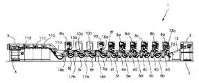
図1は、印刷されていない紙パイル3がある給紙装置2を備えた、タンデム型の表面印刷枚葉紙オフセット印刷機を示している。この機械は、4種類のプロセスインキおよび場合によりさらに2種類の特色インキのための6つの印刷ユニット8aから8fと、第1の塗工ユニット9aと、その後に続く2つの乾燥塔10aおよび10bと、第2の塗工ユニット9bと、枚葉紙パイル6のための排紙装置5とを有している。排紙装置5のチェーン案内部の領域には、さらに別の4つの差込式乾燥機11aから11dがチェーン案内部の間で、相応に延長されたデリバリーに組み込まれている。
FIG. 1 shows a tandem type surface printing sheet offset printing press equipped with a paper feeding device 2 with a
符号4aから4fは印刷ユニットの圧胴であり、符号14aおよび14bは塗工ユニットの圧胴であり、符号17aおよび17bは乾燥塔の圧胴である。印刷ユニットの間にある搬送胴5bから5f、塗工ユニット9aおよび9bの手前にある搬送胴5gおよび5j、および乾燥塔の手前にある搬送銅5hおよび5iは、圧胴と連携しながら、印刷された枚葉紙を機械を通過するように運んでいく。
乾燥塔10aおよび10bは、熱風乾燥機と赤外放射器ユニットとが組み合わされたものであり、これらによって、塗工ユニット9aで塗布された水性の分散性塗料が乾かされてから、第2の塗工ユニット9bが第2の塗工層を、乾燥した第1の塗工層の上に重ねる。両方の乾燥塔10aおよび10bの各々は、60Wの電気的な接続負荷を有している。
The
差込式乾燥機11aから11dは、同じく赤外乾燥機と熱風乾燥機が組み合わされたものであり、ハイデルベルガー・ドゥルックマシーネンAG社により"DryStar 3000"の商品名で提供されており、1つの差込部ごとに電気的な最大の接続負荷66kWを有している。
The plug-in
このような種類の印刷機は、たとえばSpeedmaster XL 105-6-LYYLX3の名称で、ハイデルベルガー・ドゥルックマシーネンAG社により75/105cmの判型について提供されている。この機械は全体で21mの長さを有しているが、塔10aおよび10bと差込式乾燥機11aから11dによってデリバリー延長部で必要となる乾燥区間だけで5.3mを占めている。
A printing machine of this kind is offered, for example, in the name of Speedmaster XL 105-6-LYYLX3, for 75/105 cm format by Heidelberger Drukmaschinen AG. This machine has a total length of 21 m, but occupies 5.3 m only in the drying section required at the delivery extension by the
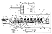
図2は、この機械を本発明に基づいて改良した実施形態で示している。ここでは乾燥塔10bが省略されており、4つの差込式乾燥機11aから11dを備える延長型のデリバリーに代えて、両方の差込式乾燥機11aおよび11bだけですませることができる、乾燥区間が半分になった短縮型の排紙装置15が用いられている。それ以外の点では、図1に示す機械と比べたとき、同じ部分には同じ符号が付されており、ここで再度説明はしない。
FIG. 2 shows this machine in an improved embodiment according to the invention. Here, the drying
乾燥塔10aと差込式乾燥機11aおよび11bの排気は、排気管21aおよび21bを介して還流凝縮器22を通るように誘導される。この還流凝縮器22で、約70℃の高温の排気が熱交換器23を通じて温水循環路の供給流30を加熱する。この循環路には、供給流ポンプ25と、モータ式の三方形弁24と、温水蓄積器26とがある。熱交換器26にある温度センサ27、還流凝縮器の出口にある温度センサ28、および温水加熱の供給流回路にある温度センサ29を通じてモータ式の三方形弁24が制御され、それにより、還流凝縮器が放出する不要な余剰の熱が蓄熱器26を加熱し、それに対して蓄熱器は、熱循環路の熱が不足したときに、高温の水を供給流回路30へ放出する量を増やすようになっている。
The exhaust from the drying
そして温水循環路によって、両方の塗工ユニット9bおよび9aの圧胴14bおよび14a、ならびに給紙装置2の給紙台112が加熱される。
Then, the pressure drums 14b and 14a of both the
塗工ユニット9bの圧胴14bには、供給配管31を介して、約60℃の供給流温度の温水が供給される。この温度は温度センサ32bによって監視され、混合弁33bによって調節される。圧胴14bから戻って流れていく水は、これよりも低い約50℃の温度を有しており、第2の混合弁33aによって、第1の塗工ユニット9aの圧胴14aの流入部35に供給される。ここにも流入温度を測定するためのセンサ32aが設けられている。
Hot water having a supply flow temperature of about 60 ° C. is supplied to the
圧胴14aおよび14bは、たとえば特許文献2に記載されているように、温水接続部のための回転伝達挿通部と、胴壁に刻設された配管システムとを備えていてよい。
The
圧胴14aから戻り配管36を介して流出していく水は、第3の混合弁38を介して、温度調節式の給紙台112のための供給流配管39へ約30℃の温度で供給される。ここでもセンサ37が流入部39で温度を計測する。給紙台112の帰還流接続部は、還流凝縮器22にある熱交換器23の帰還流40に連通している。
The water flowing out from the
供給流31の温度T1、供給流35の温度T2、および供給流39の温度T3を、上述した60℃、50℃、および30℃のレベルに保つために、混合弁33a,33bおよび38は、温度センサ32a,32bおよび37の信号に応じて制御部42によって操作される。同じく制御部42と接続されている追加加熱部41が、還流凝縮器22または温水蓄積器26から供給される温水の温度が十分ではないときに、たとえば印刷ジョブを開始するときや温水蓄積器が低温のときに、制御部42によってスイッチを投入される。
In order to maintain the temperature T1 of the
この装置の作用形態は次のとおりである。印刷ユニット8aから8bの搬送胴5bから5gおよび圧胴4aから4fによって印刷機を通過して運ばれる枚葉紙は、塗工ユニット9aに達したときに約25℃から30℃の温度を有している。印刷ユニットは、その内部で生成される廃熱に基づいて、ほぼこの温度になっており、これが、機械を通過して運ばれる印刷枚葉紙にとっての周囲温度であることを考慮する。最初から安定した印刷プロセスが行われるようにこの温度を設定するために、給紙台112は約30℃の温水で温度調節され、それにより、給紙装置2で冷たい紙パイルが供給されたときでも、取り出された枚葉紙はすでに最初の印刷ユニット8aで所望の約25℃の温度になって到着し、印刷される。
The mode of operation of this device is as follows. The sheet conveyed through the printing press by the
そして、印刷されて第1の塗工層が与えられた枚葉紙は、第1の塗工ユニット9aの圧胴14aとの接触によって約37℃の温度まで暖められる。この37℃は、約25℃の周囲温度で枚葉紙が第1の乾燥塔10aに進入したと仮定した場合に、図1に示す機械の両方の乾燥塔10aおよび10bの通過後に枚葉紙が暖められて達するはずの定常温度に相当している。75/105の判型で坪量135g/m2の枚葉紙については、圧胴14aを通じて裏面からなされる枚葉紙の約12℃の加熱は、およそ1.66kJのエネルギー注入に相当している。これは、機械速度が1時間あたり18,000枚の場合、すなわち1秒あたり5枚の場合、乾燥塔が効率η=1を有していると想定すると、8.3kWの電気出力の等価量に相当する。ただしこのような効率は、たとえば赤外放射器の場合には当てはまらない。その場合、効率は約25%である。
Then, the printed sheet provided with the first coating layer is heated to a temperature of about 37 ° C. by contact with the
以上により、第2の乾燥塔10bを省略することができる。
Thus, the
乾燥塔10aを通過した後、枚葉紙は第2の塗工ユニット9bで再度塗工され、その際に、60℃の温度の圧胴14bと接触する。枚葉紙はそこに約37℃の温度で到着しており、再び約7℃だけ加熱されて44℃になる。このようにして、塗布された第2の塗工層の水分が、事実上、排紙装置15の両方のモジュール11aおよび11bで構成される乾燥ユニットの第1のモジュール11aへ枚葉紙が進入した直後に始まるようにすることができる。上述した方策によって、ほぼ半分の値にまで短縮された乾燥区間だけで十分なので、図1に示す機械にさらに設けられている別の差込式乾燥機11cおよび11dは省略することができる。ただし、デリバリーの乾燥機が強力な対流式の(すなわち熱風のみによる)乾燥を行い、上述した44℃の温度を下回る定常温度が生じるように熱風の温度が選択されているときは、進入時の44℃より低い温度で枚葉紙を排紙することもできる(パイル温度)。
After passing through the drying
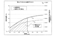
本発明によって達成される効果は、図3と図4に示すグラフを参照すると理解することができる。図3は、100℃の温度の熱風乾燥機における、塗工された枚葉紙の温度上昇を示しており、枚葉紙は20℃の温度で乾燥機に進入するものと仮定している。0.4秒の滞留時間(これは、1時間あたり15,000枚の印刷速度の場合に、枚葉紙が通常1.6mの乾燥区間を通過するのに要する時間である)の後、枚葉紙の温度は約32℃まで、すなわち約12℃だけ上昇している。塗工層からの水分の気化が、時間に対して同じくプロットされている。気化率は枚葉紙すなわち紙基材の温度に強く依存している。気化率は、想定される34℃の枚葉紙温度で約4g/m2secに向って収斂していくが、そこへ完全には到達しない。この時点では、枚葉紙はとうに乾燥機から出ているからである。気化した水分量は、符号VRで表した気化率の下側のハンチングを付した面積に相当している。 The effect achieved by the present invention can be understood with reference to the graphs shown in FIGS. FIG. 3 shows the temperature rise of the coated sheet in a hot air dryer at a temperature of 100 ° C., and it is assumed that the sheet enters the dryer at a temperature of 20 ° C. After a 0.4 second dwell time (this is the time it takes for the sheet to pass through a drying section of typically 1.6 m at a printing speed of 15,000 sheets per hour) The temperature of the leaf paper has risen to about 32 ° C., ie about 12 ° C. The water vaporization from the coating layer is also plotted against time. The evaporation rate is strongly dependent on the temperature of the sheet, ie the paper substrate. The vaporization rate converges toward about 4 g / m 2 sec at the assumed sheet temperature of 34 ° C., but does not reach it completely. At this point, the sheet is finally out of the dryer. The vaporized water content corresponds to the area marked with the lower hunting evaporation rate, expressed by symbol V R.
それに対して図4には、枚葉紙がすでに34℃になって乾燥機に進入するケースについての比率が示されている。ここでは最初からすぐに4g/m2secの気化率が生じており、気化した水分量、すなわち乾燥機で放散される水分量は2倍近くまで増えている。 On the other hand, FIG. 4 shows the ratio for the case where the sheet is already 34 ° C. and enters the dryer. Here, a vaporization rate of 4 g / m 2 sec is generated immediately from the beginning, and the amount of water vaporized, that is, the amount of water dissipated in the dryer, has increased to nearly double.
2つの塗工ユニットを備える表面印刷機の実施形態を例にとって、本発明を説明した。しかしながら本発明は、ただ1つの塗工ユニットを備える機械や、裏面印刷機でも同様に適用することができ、たとえば、塗工ユニットと乾燥装置が反転装置の前に、または表面印刷側の第1の印刷ユニットの前に配置されており、他ならぬその個所で、乾燥区間を短く抑えるようになっている機械配列でも適用できる。さらに本発明は、たとえばウェットオフセット印刷用のコンベンショナルインキや、スクリーンローラとチャンバ型ドクターを備える簡易型インキ装置によって塗布される低粘度のアニロックスインキを効率的に乾かすために、塗工ユニットをもたない枚葉紙印刷機でも適用することができる。この場合、枚葉紙は乾燥機へ進入する前に、最後の印刷ユニットの圧胴によって予加熱される。それにより、アニロックスインキの溶剤部分の気化が、乾燥ユニットへ枚葉紙が進入した直後に始まるようにすることができる。 The present invention has been described by taking as an example an embodiment of a surface printing machine comprising two coating units. However, the present invention can be similarly applied to a machine having only one coating unit or a backside printing machine. For example, the coating unit and the drying device are arranged in front of the reversing device or the first on the front surface printing side. It can also be applied to a machine arrangement that is arranged in front of the printing unit and is designed to keep the drying section short at other points. Furthermore, the present invention has a coating unit for efficiently drying, for example, conventional ink for wet offset printing and low-viscosity anilox ink applied by a simple ink apparatus having a screen roller and a chamber type doctor. It can be applied even with no sheet-fed printing press. In this case, the sheet is preheated by the impression cylinder of the last printing unit before entering the dryer. Thereby, the vaporization of the solvent part of the anilox ink can be started immediately after the sheet enters the drying unit.
1 表面印刷枚葉紙オフセット印刷機
2 給紙装置
3 紙パイル
4a−f 圧胴
5 排紙装置
5b−5j 搬送胴
6 枚葉紙パイル
8a−8f 印刷ユニット
9a,9b 塗工ユニット
10a,10b 乾燥塔
11a−11d 差込式乾燥機
12,112 給紙台
14a,14b 圧胴
15 排紙装置
17a,17b 圧胴
21a,21b 廃熱管
22 還流凝縮器
23 熱交換器
24 三方形弁
25 供給流ポンプ
26 温水蓄積器
27,28,29 温度センサ
30 供給流開路
31,35,39 供給配管
32a,32b,37 温度センサ
33a,33b,38 混合弁
40 帰還流
42 制御部
DESCRIPTION OF SYMBOLS 1 Front surface printed sheet offset printing machine 2
Claims (19)
枚葉紙が、前記乾燥装置(10,11)へ進入する前にすでに周囲温度を上回る温度まで、前記印刷ユニットまたは前記塗工ユニット(9a,9b)において、加熱された圧胴との接触によって加熱されることを特徴とする、枚葉紙印刷機において印刷または塗工された枚葉紙を乾かす方法。 In a method of drying a printed or coated sheet in a sheet printing machine (1) comprising a plurality of printing units (8) or coating units (9) and a drying device,
Sheet is, to a temperature above the already ambient temperature before entering the into the drying device (10, 11), the printing unit or the coating unit (9a, 9b) in, by contact with the heated impression cylinder A method for drying a sheet of paper printed or coated in a sheet press, characterized by being heated.
枚葉紙進行方向に見て前記乾燥装置の手前に配置された最後の印刷ユニットまたは塗工ユニット(9a,9b)が加熱可能な圧胴を有しており、その動作温度は、前記圧胴から出ていく枚葉紙が前記乾燥装置(10a,11)へ進入するときに周囲温度を上回る温度まで加熱されるように選択されていることを特徴とする枚葉紙印刷機。 A plurality of printing units (8a-8f) or coating units (9a, 9b) and a drying device (10a, 11a, 11b) for drying the ink layer or coating layer printed on the sheet with heat. In the sheet-fed printing machine (1) provided,
The last printing unit or coating unit (9a, 9b) arranged in front of the drying device as viewed in the sheet traveling direction has a pressure drum that can be heated, and the operating temperature thereof is the pressure cylinder. A sheet-fed printing press, characterized in that it is selected so that the sheet coming out of it is heated to a temperature above ambient temperature when entering the drying device (10a, 11).
Applications Claiming Priority (2)
| Application Number | Priority Date | Filing Date | Title |
|---|---|---|---|
| DE102006058238 | 2006-12-11 | ||
| DE102006058238.1 | 2006-12-11 |
Publications (3)
| Publication Number | Publication Date |
|---|---|
| JP2008143176A JP2008143176A (en) | 2008-06-26 |
| JP2008143176A5 JP2008143176A5 (en) | 2010-12-09 |
| JP5089357B2 true JP5089357B2 (en) | 2012-12-05 |
Family
ID=39496464
Family Applications (1)
| Application Number | Title | Priority Date | Filing Date |
|---|---|---|---|
| JP2007313391A Expired - Fee Related JP5089357B2 (en) | 2006-12-11 | 2007-12-04 | How to dry a sheet printed or coated on a printing press |
Country Status (3)
| Country | Link |
|---|---|
| US (2) | US20080134915A1 (en) |
| JP (1) | JP5089357B2 (en) |
| CN (1) | CN101200130B (en) |
Families Citing this family (10)
| Publication number | Priority date | Publication date | Assignee | Title |
|---|---|---|---|---|
| JP2011194823A (en) * | 2010-03-23 | 2011-10-06 | Seiko Epson Corp | Method for printing by inkjet recording method |
| DE102012007049A1 (en) * | 2011-04-27 | 2012-10-31 | Heidelberger Druckmaschinen Ag | Printing process and perfector for perfecting on bows |
| CN103507395A (en) * | 2012-06-19 | 2014-01-15 | 厦门黛丽诗自动化设备有限公司 | Full-automatic screen printer |
| CN102837489A (en) * | 2012-09-13 | 2012-12-26 | 江苏昌昇集团股份有限公司 | Multiple-operation lustering offset press |
| GB2508155B (en) | 2012-11-21 | 2016-10-26 | Kenwood Ltd | Self-stirring food receptacle |
| CN104476917A (en) * | 2014-12-31 | 2015-04-01 | 陈淼 | Laminating polishing heat energy recovery unit |
| US11376878B2 (en) | 2018-02-06 | 2022-07-05 | Hewlett-Packard Development Company, L.P. | Rendering system energy recovery |
| CN108544866A (en) * | 2018-04-18 | 2018-09-18 | 山东临沂新华印刷物流集团有限责任公司 | Double-sided printing process, device and system |
| CN110039892A (en) * | 2019-04-30 | 2019-07-23 | 中山松德印刷机械有限公司 | Back painting formula double-station compounding machine and its working method before a kind of |
| CN111619086B (en) * | 2020-05-08 | 2022-03-15 | 山东宜居新材料科技有限公司 | Production device and production method of wood-plastic composite material |
Family Cites Families (32)
| Publication number | Priority date | Publication date | Assignee | Title |
|---|---|---|---|---|
| US2329152A (en) * | 1940-07-11 | 1943-09-07 | J M Huber Inc | Method and apparatus for printing |
| CH274259A (en) | 1949-05-21 | 1951-03-31 | Horn Josef | Method and machine for producing two-color prints on sheets in one operation. |
| DE3439090C2 (en) * | 1984-10-25 | 1987-01-08 | Albert-Frankenthal Ag, 6710 Frankenthal | Cylinders for web material processing machines |
| JPS63106635U (en) * | 1986-12-27 | 1988-07-09 | ||
| EP0451100B1 (en) * | 1990-04-06 | 1994-08-17 | De La Rue Giori S.A. | Impression cylinder device in a gravure printing machine for web printing |
| DE4139120A1 (en) * | 1990-11-30 | 1992-06-04 | Juergen K Keck | Drying assembly for laminated paper sheets at offset printing press - esp. for drying UV varnish, uses hot air to increase varnish viscosity before UV drying stage |
| US5520763A (en) * | 1992-02-03 | 1996-05-28 | Moore Business Forms, Inc. | Intelligent foil transfer |
| US6293196B1 (en) * | 1993-10-06 | 2001-09-25 | Howard W. DeMoore | High velocity, hot air dryer and extractor |
| EP0738583B1 (en) * | 1993-12-29 | 1998-10-14 | Kira Corporation | Sheet laminate forming method |
| JPH0919998A (en) * | 1995-07-05 | 1997-01-21 | Toppan Printing Co Ltd | Printing method and printing machine |
| JPH10296953A (en) * | 1997-04-23 | 1998-11-10 | Komori Corp | Coating apparatus |
| JPH11138742A (en) * | 1997-11-05 | 1999-05-25 | Mitsubishi Heavy Ind Ltd | Sheet-feed printer for double-side printing |
| DE19807505A1 (en) * | 1998-02-21 | 1999-08-26 | Roland Man Druckmasch | Rotary sheet printer for multicolored printing |
| US6810800B1 (en) * | 1999-10-08 | 2004-11-02 | Koenig & Bauer Aktiengesellschaft | Cylinder for a rotary press |
| AU4246101A (en) | 2000-03-16 | 2001-09-24 | Eltosch Torsten Schmidt Gmbh | Method and device for utilising the waste heat that has accumulated during the supply of forced draught/compressed air to a printing press |
| DE10020648A1 (en) | 2000-04-27 | 2001-10-31 | Heidelberger Druckmasch Ag | Sheet-fed printer has sheet-separator, feeder, with marker, preliminary gripper, feeder and transporter drums, screen roller and ductor |
| DE10024370A1 (en) | 2000-05-17 | 2001-11-22 | Roland Man Druckmasch | Device for surface processing of printed sheets includes first and second axially parallel rollers and heater for heating printed sheet in area of rolling gap between the two rollers |
| JP2002079774A (en) * | 2000-06-26 | 2002-03-19 | Fuji Photo Film Co Ltd | Method of lithographic printing, original film for printing and equipment for printing |
| JP2002166677A (en) * | 2000-11-30 | 2002-06-11 | Komori Corp | Printer |
| KR100382930B1 (en) * | 2001-02-21 | 2003-05-09 | 엘지전자 주식회사 | Structure for reducing loss of linear compressor |
| JP4412447B2 (en) * | 2001-05-29 | 2010-02-10 | 東洋製罐株式会社 | Temperature control method and apparatus for printing press |
| DE10149009B4 (en) * | 2001-10-04 | 2009-11-12 | Manroland Ag | Process for processing an inhibitor and oligomer-containing printing ink in a printing unit of a rotary printing press |
| DE10152593A1 (en) * | 2001-10-24 | 2003-05-08 | Koenig & Bauer Ag | Device for printing material and printing unit cooling by means of cooled blown air on sheet-fed rotary printing machines |
| DE10305594B4 (en) * | 2002-03-05 | 2014-12-31 | Heidelberger Druckmaschinen Ag | press |
| JP2004299228A (en) * | 2003-03-31 | 2004-10-28 | Orient Syst Eng:Kk | Printing press |
| US7016027B2 (en) | 2003-05-08 | 2006-03-21 | Infineon Technologies Ag | System and method for quantifying errors in an alternating phase shift mask |
| JP4460915B2 (en) * | 2003-06-13 | 2010-05-12 | 三菱重工業株式会社 | Double-sided sheet-fed printing machine |
| DE10334657A1 (en) * | 2003-07-30 | 2005-02-17 | Koenig & Bauer Ag | Method and device for printing substrate and printing machine cooling |
| DE102005011696A1 (en) | 2004-04-13 | 2005-11-24 | Man Roland Druckmaschinen Ag | Rotary foil transfer printing process has applied heat to aid transfer onto sheet material |
| DE102005022595B4 (en) * | 2004-06-04 | 2016-01-28 | Heidelberger Druckmaschinen Ag | Method for tempering a cylinder of a printing press |
| JP4995442B2 (en) * | 2004-07-16 | 2012-08-08 | ハイデルベルガー ドルツクマシーネン アクチエンゲゼルシヤフト | How to adjust the temperature |
| DE102005042956B4 (en) | 2004-10-06 | 2019-04-25 | Heidelberger Druckmaschinen Ag | press |
-
2007
- 2007-12-04 JP JP2007313391A patent/JP5089357B2/en not_active Expired - Fee Related
- 2007-12-11 US US11/954,150 patent/US20080134915A1/en not_active Abandoned
- 2007-12-11 CN CN2007101996024A patent/CN101200130B/en not_active Expired - Fee Related
-
2009
- 2009-07-20 US US12/505,703 patent/US8166877B2/en not_active Expired - Fee Related
Also Published As
| Publication number | Publication date |
|---|---|
| CN101200130A (en) | 2008-06-18 |
| JP2008143176A (en) | 2008-06-26 |
| US8166877B2 (en) | 2012-05-01 |
| US20090277352A1 (en) | 2009-11-12 |
| US20080134915A1 (en) | 2008-06-12 |
| CN101200130B (en) | 2012-05-09 |
Similar Documents
| Publication | Publication Date | Title |
|---|---|---|
| JP5089357B2 (en) | How to dry a sheet printed or coated on a printing press | |
| JP5766054B2 (en) | A sheet processing machine with one or more dryers | |
| JP2997924B2 (en) | Tower type multi-color printing device | |
| JPH07214756A (en) | Printing web heating device of press | |
| JP2009092374A (en) | Hot-air drying apparatus and method for drying printed material | |
| JP5992161B2 (en) | Machine for processing sheets and method for drying aqueous varnish coated sheets | |
| JP2008143176A5 (en) | ||
| US8567316B2 (en) | Method for controlling a temperature of a press and press having a temperature control device | |
| JP4980980B2 (en) | Method and apparatus for metering coating liquid on a processing machine | |
| JP2005335383A (en) | Direct coupled driver for drum of processing machine | |
| US5758580A (en) | Printing unit using various ink types | |
| JP5755415B2 (en) | Image recording apparatus and drying control method | |
| DE102007056899A1 (en) | Drying method e.g. for printed or varnished sheets in printing press, involves sheets heated to temperature higher than ambient temperature before sheets enter dryer | |
| US6209456B1 (en) | Web- and sheet-fed printing unit using various ink types, particularly water-based inks | |
| CN112105505B (en) | Processing machine with a radiation dryer and method for operating such a dryer | |
| US20120272847A1 (en) | Printing method and perfecting printing press for recto and verso printing on sheets | |
| KR200477252Y1 (en) | gravure printing device using waste heat | |
| JP5870106B2 (en) | Recording substrate processing apparatus and method | |
| US11247493B2 (en) | Device and method for drying a recording medium with reduced connected load | |
| WO2018139189A1 (en) | Impermeable sheet substrate surface drying device, printing device, and printing method | |
| JP2006315219A (en) | Water-based varnish drying apparatus of perfecting press | |
| JP2008087354A (en) | Drying device for printers, and printer | |
| EP4013618B1 (en) | Refrigation unit for a printing machine and printing machine | |
| US11007797B2 (en) | Dryer for drying images on coated substrates in aqueous ink printers | |
| JP4430295B2 (en) | Method and apparatus for cooling a printing material in a rotary printing press |
Legal Events
| Date | Code | Title | Description |
|---|---|---|---|
| A521 | Request for written amendment filed |
Free format text: JAPANESE INTERMEDIATE CODE: A523 Effective date: 20101025 |
|
| A621 | Written request for application examination |
Free format text: JAPANESE INTERMEDIATE CODE: A621 Effective date: 20101025 |
|
| A131 | Notification of reasons for refusal |
Free format text: JAPANESE INTERMEDIATE CODE: A131 Effective date: 20120508 |
|
| A521 | Request for written amendment filed |
Free format text: JAPANESE INTERMEDIATE CODE: A523 Effective date: 20120711 |
|
| TRDD | Decision of grant or rejection written | ||
| A01 | Written decision to grant a patent or to grant a registration (utility model) |
Free format text: JAPANESE INTERMEDIATE CODE: A01 Effective date: 20120828 |
|
| A01 | Written decision to grant a patent or to grant a registration (utility model) |
Free format text: JAPANESE INTERMEDIATE CODE: A01 |
|
| A61 | First payment of annual fees (during grant procedure) |
Free format text: JAPANESE INTERMEDIATE CODE: A61 Effective date: 20120911 |
|
| FPAY | Renewal fee payment (event date is renewal date of database) |
Free format text: PAYMENT UNTIL: 20150921 Year of fee payment: 3 |
|
| R150 | Certificate of patent or registration of utility model |
Free format text: JAPANESE INTERMEDIATE CODE: R150 |
|
| LAPS | Cancellation because of no payment of annual fees |