JP5086240B2 - Dual needle feeding system - Google Patents
Dual needle feeding system Download PDFInfo
- Publication number
- JP5086240B2 JP5086240B2 JP2008507728A JP2008507728A JP5086240B2 JP 5086240 B2 JP5086240 B2 JP 5086240B2 JP 2008507728 A JP2008507728 A JP 2008507728A JP 2008507728 A JP2008507728 A JP 2008507728A JP 5086240 B2 JP5086240 B2 JP 5086240B2
- Authority
- JP
- Japan
- Prior art keywords
- instrument
- lumen
- needle
- catheter
- catheter body
- Prior art date
- Legal status (The legal status is an assumption and is not a legal conclusion. Google has not performed a legal analysis and makes no representation as to the accuracy of the status listed.)
- Expired - Fee Related
Links
Images


Classifications
-
- A—HUMAN NECESSITIES
- A61—MEDICAL OR VETERINARY SCIENCE; HYGIENE
- A61M—DEVICES FOR INTRODUCING MEDIA INTO, OR ONTO, THE BODY; DEVICES FOR TRANSDUCING BODY MEDIA OR FOR TAKING MEDIA FROM THE BODY; DEVICES FOR PRODUCING OR ENDING SLEEP OR STUPOR
- A61M25/00—Catheters; Hollow probes
- A61M25/01—Introducing, guiding, advancing, emplacing or holding catheters
- A61M25/06—Body-piercing guide needles or the like
-
- A—HUMAN NECESSITIES
- A61—MEDICAL OR VETERINARY SCIENCE; HYGIENE
- A61M—DEVICES FOR INTRODUCING MEDIA INTO, OR ONTO, THE BODY; DEVICES FOR TRANSDUCING BODY MEDIA OR FOR TAKING MEDIA FROM THE BODY; DEVICES FOR PRODUCING OR ENDING SLEEP OR STUPOR
- A61M25/00—Catheters; Hollow probes
- A61M25/0021—Catheters; Hollow probes characterised by the form of the tubing
- A61M25/0023—Catheters; Hollow probes characterised by the form of the tubing by the form of the lumen, e.g. cross-section, variable diameter
- A61M25/0026—Multi-lumen catheters with stationary elements
- A61M25/003—Multi-lumen catheters with stationary elements characterized by features relating to least one lumen located at the distal part of the catheter, e.g. filters, plugs or valves
-
- A—HUMAN NECESSITIES
- A61—MEDICAL OR VETERINARY SCIENCE; HYGIENE
- A61M—DEVICES FOR INTRODUCING MEDIA INTO, OR ONTO, THE BODY; DEVICES FOR TRANSDUCING BODY MEDIA OR FOR TAKING MEDIA FROM THE BODY; DEVICES FOR PRODUCING OR ENDING SLEEP OR STUPOR
- A61M25/00—Catheters; Hollow probes
- A61M25/0021—Catheters; Hollow probes characterised by the form of the tubing
- A61M25/0023—Catheters; Hollow probes characterised by the form of the tubing by the form of the lumen, e.g. cross-section, variable diameter
- A61M25/0026—Multi-lumen catheters with stationary elements
- A61M2025/0034—Multi-lumen catheters with stationary elements characterized by elements which are assembled, connected or fused, e.g. splittable tubes, outer sheaths creating lumina or separate cores
-
- A—HUMAN NECESSITIES
- A61—MEDICAL OR VETERINARY SCIENCE; HYGIENE
- A61M—DEVICES FOR INTRODUCING MEDIA INTO, OR ONTO, THE BODY; DEVICES FOR TRANSDUCING BODY MEDIA OR FOR TAKING MEDIA FROM THE BODY; DEVICES FOR PRODUCING OR ENDING SLEEP OR STUPOR
- A61M25/00—Catheters; Hollow probes
- A61M25/0021—Catheters; Hollow probes characterised by the form of the tubing
- A61M25/0023—Catheters; Hollow probes characterised by the form of the tubing by the form of the lumen, e.g. cross-section, variable diameter
- A61M25/0026—Multi-lumen catheters with stationary elements
- A61M2025/0037—Multi-lumen catheters with stationary elements characterized by lumina being arranged side-by-side
-
- A—HUMAN NECESSITIES
- A61—MEDICAL OR VETERINARY SCIENCE; HYGIENE
- A61M—DEVICES FOR INTRODUCING MEDIA INTO, OR ONTO, THE BODY; DEVICES FOR TRANSDUCING BODY MEDIA OR FOR TAKING MEDIA FROM THE BODY; DEVICES FOR PRODUCING OR ENDING SLEEP OR STUPOR
- A61M25/00—Catheters; Hollow probes
- A61M25/0067—Catheters; Hollow probes characterised by the distal end, e.g. tips
- A61M25/0068—Static characteristics of the catheter tip, e.g. shape, atraumatic tip, curved tip or tip structure
- A61M25/0071—Multiple separate lumens
Landscapes
- Health & Medical Sciences (AREA)
- Life Sciences & Earth Sciences (AREA)
- Biophysics (AREA)
- Pulmonology (AREA)
- Engineering & Computer Science (AREA)
- Anesthesiology (AREA)
- Biomedical Technology (AREA)
- Heart & Thoracic Surgery (AREA)
- Hematology (AREA)
- Animal Behavior & Ethology (AREA)
- General Health & Medical Sciences (AREA)
- Public Health (AREA)
- Veterinary Medicine (AREA)
- Infusion, Injection, And Reservoir Apparatuses (AREA)
Description
本発明は、複数のニードルのような複数の器具を、1つの送り装置を使用して治療部位まで送ることに関するものである。 The present invention relates to delivering a plurality of instruments, such as a plurality of needles, to a treatment site using a single feeder.
心臓血管疾患に起因する疾病や死亡の主成因は、冠状動脈及び/または末梢血管系に血液を送る血管の部分的または完全な閉塞の結果として生じる。こうした血管が部分的に閉塞すると、血流が欠乏するため、こうした血管から血液供給を受けている筋肉組織に虚血が生じ、結果として、筋肉の収縮及び適正な機能が阻害される。血流が完全に遮断されると、筋肉組織の壊死が生じる。 The major cause of illness and death due to cardiovascular disease occurs as a result of partial or complete occlusion of blood vessels that deliver blood to the coronary arteries and / or peripheral vasculature. When these blood vessels are partially occluded, the blood flow is deficient, resulting in ischemia in the muscular tissue receiving blood supply from these blood vessels, resulting in inhibition of muscle contraction and proper function. When blood flow is completely blocked, muscle tissue necrosis occurs.
血管の閉塞は、一般に、罹患血管内の血流量を機械的に増大させることによって処置される。こうした血流量の機械的増大は、閉塞部位に近接して及び閉塞部位から遠位に天然または合成導管を取り付けることによって、バイパス移植片を設ける外科技術、あるいは、さまざまな手段によって、血管内腔の閉塞部位を物理的に拡張する血管再開通術を用いて施される場合が多い。これらの血管再開通手法には、バルーン、血管内手術刀(アテローム切除術)、及び、血管内ドリルといった器具が必要とされる。外科的アプローチには、重大な病的状態や、死亡さえ付随して生じるが、一方、血管形成タイプの手法は、多くの場合、再発性狭窄症を併発する。 Vessel occlusion is generally treated by mechanically increasing blood flow in the affected blood vessel. This mechanical increase in blood flow can be achieved by surgical techniques for providing bypass grafts by attaching natural or synthetic conduits proximate to and distal to the occlusion site, or by various means, in the vessel lumen. Often performed using a revascularization procedure that physically dilates the occluded site. These revascularization techniques require instruments such as balloons, endovascular surgical blades (atherectomy), and intravascular drills. Surgical approaches are associated with serious morbidity and even death, while angiogenic type techniques often accompany recurrent stenosis.
個人によっては、血管閉塞が、自然作用によって部分的に代償されることもあり、障害のある血管の機能に取って代わるために新しい血管が形成され(「血管新生」と称される)、小血管が拡大される(「動脈形成)と称される)。これらの新しい導管は、欠乏した組織に対する血流の回復を促進し、それによって、閉塞血管まわりに「自然バイパス」を構成する。しかしながら、個人によっては、十分な側副血管を生成して、心臓血管疾患によって生じる血流量の減少を十分に補償することができない場合もある。従って、虚血の治療のために、冠状動脈と抹消動脈の閉塞に起因する血液損失を補償するため、治療的血管新生の自然作用の刺激を促進する薬剤を送る方法と装置を提供するのが望ましいであろう。治療部位へ薬剤を送ることは、他の多くの治療的処置または方法において必要とされる。 In some individuals, vaso-occlusion may be partially compensated by natural effects, and new blood vessels are formed to replace the function of impaired blood vessels (referred to as “angiogenesis”) and small The blood vessels are dilated (referred to as “arteriogenesis”) These new conduits promote blood flow recovery to the depleted tissue, thereby creating a “natural bypass” around the occluded blood vessels. However, some individuals may not be able to generate enough collateral vessels to fully compensate for the reduction in blood flow caused by cardiovascular disease. Accordingly, for the treatment of ischemia, there is provided a method and apparatus for delivering a drug that promotes stimulation of the natural effects of therapeutic angiogenesis to compensate for blood loss due to occlusion of coronary and peripheral arteries. Would be desirable. Delivery of the drug to the treatment site is required in many other therapeutic procedures or methods.
例えば、心臓血管に関連した、癌に関連したいくつかの治療、及び、いくつかの外科的療法または最小限に侵襲的な治療の場合、管腔内、心臓内、または、心室内に、徐放性基質の、または、徐放性マトリックスを含む治療薬を注入するのが望ましい場合がある。しかしながら、あいにく、所望の治療部位に治療薬を保持するのは一般に困難である。例えば、心臓血管に関連した治療の場合、こうした治療後に、注入部位に保持される徐放性マトリックスが30%を超えることはめったにない。徐放性マトリックスの損失は、一般に、初期注入中か、あるいは、ニードル位置からの逆流の結果として発生する。ニードル位置からの逆流は、マトリックス材料を送るのに必要な流体量が過剰であるために、あるいは、注入部位からニードルを取り外す際、マトリックス材料が漏出する前に、その部位が密封されないために、生じる可能性がある。マトリックス材料が漏出する影響は、マトリックスとまわりの血液または流体との相互作用に応じて何倍にもなる可能性がある。 For example, some treatments related to cardiovascular, cancer-related, and some surgical or minimally invasive treatments, intraluminal, intracardiac, or intraventricular, It may be desirable to inject a therapeutic agent comprising a releasable matrix or a sustained release matrix. Unfortunately, however, it is generally difficult to retain the therapeutic agent at the desired treatment site. For example, in the case of cardiovascular related treatments, the sustained release matrix retained at the injection site rarely exceeds 30% after such treatment. Sustained release matrix loss generally occurs during initial injection or as a result of backflow from the needle position. The backflow from the needle position is due to the excessive amount of fluid needed to deliver the matrix material or because the site is not sealed before the matrix material leaks when removing the needle from the injection site. It can happen. The effect of leakage of the matrix material can be many times depending on the interaction of the matrix with the surrounding blood or fluid.
マトリックス材料の損失及び放出の結果、投与薬剤の送り量にばらつきが生じる可能性がある。投与薬剤の送り量にばらつきがあると、結果として、さらに、治療薬の送りが、所望のまたは最適な治療濃度域外の量になる。動脈または心室治療部位の場合、徐放性マトリックスに血栓形成効果があると、二次反応が生じて、動脈または心室領域に深刻な結果をもたらす可能性のある血栓が形成されることになる。薬剤を治療部位に保持できるようなやり方で薬剤を送るのが重要である。 As a result of the loss and release of the matrix material, there may be variations in the delivery of the administered drug. Variations in the delivery rate of the administered drug will result in further therapeutic drug delivery that is outside the desired or optimal therapeutic concentration range. In the case of an arterial or ventricular treatment site, if the sustained release matrix has a thrombus formation effect, a secondary reaction will occur resulting in the formation of a thrombus that can have serious consequences in the arterial or ventricular region. It is important to deliver the drug in such a way that it can be held at the treatment site.
治療部位に、徐放性マトリックスの治療薬または徐放性マトリックスを含む治療薬を含む、治療薬を保持することが可能な技法が、注入のために開発されている。多くの場合、1つ以上の薬剤を注入することが望ましいが、多くの受入れ部では、いったん混合されたこれらの薬剤が、厚いゲルを形成する可能性がある。他の多くの事例では、反応してもかまわなければ、ゲル・マトリックスを形成する可能性のある、いくつかの薬剤を注入するのが望ましい場合もある、従って、治療部位に注入されるまで、薬剤は分離した状態に保つ必要がある。例えば、ある心筋強化治療の場合、損傷した心筋に2つの化学成分を注入することになる。治療部位において、2つの化学成分は混合して、ゲルを形成し、心筋の壁厚を増すことになる。 Techniques have been developed for injection that can hold a therapeutic agent, including a therapeutic agent with a sustained release matrix or a therapeutic agent that includes a sustained release matrix at the treatment site. In many cases, it is desirable to inject one or more drugs, but in many receptacles, once mixed, these drugs can form a thick gel. In many other cases, it may be desirable to inject some drug that may form a gel matrix if it can be reacted, so until it is injected at the treatment site, The drug must be kept separate. For example, in some myocardial enhancement treatments, two chemical components are injected into the damaged myocardium. At the treatment site, the two chemical components will mix to form a gel and increase the wall thickness of the myocardium.
従って、本発明の目的は、治療部位での薬剤の注入(または除去)に役立つか、または、それを促進することが可能な器具を治療部位に送ることが可能な装置及び/または方法を提供することにある。 Accordingly, it is an object of the present invention to provide an apparatus and / or method that can deliver an instrument to or at the treatment site that can help or facilitate the injection (or removal) of the drug at the treatment site. There is to do.
本発明の態様は、ニードルのような2つ以上の医療器具を同時にまたは順次送ることができるようにする装置に関するものである。いくつかの態様では、装置は、1度に1つの医療器具を送ることができるように構成されている。例えば、いくつかの態様では、送り装置は、1つの器具を引っ込め、同時に、もう1つの器具を伸ばして、送るように構成することが可能である。他の態様では、2つ以上の器具を同時に伸ばして、送る。送りという用語は、注入、除去、撮像、配置、または、1つまたは複数の器具を特定の治療部位に別様に送ることを表わすものとする。本発明の多くの実施態様は、患者に薬剤を注入することが可能なニードルである器具または医療器具に関連するが、本明細書に記載の実施態様は、患者から流体を除去するために利用可能なタイプの器具、または、切除器具、撮像器具、カメラ、診断器具、移植片送り装置等のような他のタイプの医療器具といった、他の器具にも同様に適用することが可能である。 Aspects of the invention relate to an apparatus that allows two or more medical devices, such as needles, to be delivered simultaneously or sequentially. In some aspects, the device is configured to deliver one medical device at a time. For example, in some aspects, the feeder can be configured to retract one instrument and simultaneously extend and deliver another instrument. In other embodiments, two or more instruments are stretched and sent simultaneously. The term delivery is intended to refer to injection, removal, imaging, placement, or otherwise delivering one or more instruments to a particular treatment site. Although many embodiments of the present invention relate to devices that are needles or medical devices that are capable of injecting a drug into a patient, the embodiments described herein may be used to remove fluid from a patient. It is equally applicable to other instruments, such as possible types of instruments or other types of medical instruments such as ablation instruments, imaging instruments, cameras, diagnostic instruments, graft feeders and the like.
実施態様の1つは、貫通する第1の内腔と第2の内腔を備えたカテーテル本体を含む装置に関するものである。第1の内腔は、第1の器具を収容するように構成され、第2の内腔は、第2の器具を収容するように構成されている。カテーテル本体には、制御ハンドルも結合されている。制御ハンドルには、第1の器具を制御するように構成された第1の制御機構と、第2の器具を制御するように構成された第2の制御機構が含まれている。カテーテル本体の遠位部分には、送り経路が設けられている。送り経路は、カテーテル本体の遠位先端における第1の器具と第2の器具の個別導入を可能にするように構成されている。送り経路は、いかなる時点においても、第1の器具または第2の器具の一方だけしかそれを通って伸びることができないように構成されている。第1の器具と第2の器具は、治療部位に1つまたは複数の薬剤を送ることが可能なニードルとすることが可能である。 One embodiment relates to an apparatus that includes a catheter body with a first lumen and a second lumen therethrough. The first lumen is configured to receive a first instrument, and the second lumen is configured to receive a second instrument. A control handle is also coupled to the catheter body. The control handle includes a first control mechanism configured to control the first instrument and a second control mechanism configured to control the second instrument. A delivery path is provided in the distal portion of the catheter body. The delivery path is configured to allow separate introduction of the first instrument and the second instrument at the distal tip of the catheter body. The feed path is configured so that only one of the first instrument or the second instrument can extend through it at any given time. The first instrument and the second instrument can be needles capable of delivering one or more medications to the treatment site.
もう1つの実施態様は、近位セクション、遠位セクション、及び、貫通する少なくとも第1の内腔と第2の内腔を備えた、カテーテル本体を含む装置に関するものである。第1の内腔は、第1の器具を収容するように構成され、第2の内腔は、第2の器具を収容するように構成されている。第1の内腔と第2の内腔は、互いに並列に配置されている。カテーテル本体の遠位セクションには、第1の内腔と第2の内腔の間を隔てる壁はない。カテーテル本体には、制御ハンドルも結合されている。制御ハンドルには、第1の器具を制御するように構成された第1の制御機構と、第2の器具を制御するように構成された第2の制御機構が含まれている。第1の内腔と第2の内腔は、第1の器具と第2の器具のそれぞれが、その中で回転し、そこから伸びることができるように構成されている。第1と第2の器具は、それぞれ、治療部位に1つまたは複数の薬剤を送ることができるニードルとすることが可能である。 Another embodiment relates to an apparatus including a catheter body with a proximal section, a distal section, and at least a first lumen and a second lumen therethrough. The first lumen is configured to receive a first instrument, and the second lumen is configured to receive a second instrument. The first lumen and the second lumen are arranged in parallel with each other. There is no wall in the distal section of the catheter body separating the first and second lumens. A control handle is also coupled to the catheter body. The control handle includes a first control mechanism configured to control the first instrument and a second control mechanism configured to control the second instrument. The first lumen and the second lumen are configured such that each of the first instrument and the second instrument can rotate and extend therefrom. The first and second devices may each be a needle that can deliver one or more medications to the treatment site.
もう1つの実施態様は、第1のニードルと第2のニードルを備えたカテーテル本体を治療部位まで進めるステップを含む方法に関するものである。カテーテル本体は、近位セクション、遠位セクション、及び、それを貫通する少なくとも第1の内腔と第2の内腔を備えている。第1の内腔内には、第1のニードルが挿入され、第2の内腔内には、第2のニードルが挿入される。この方法には、さらに、治療部位において、カテーテル本体の遠位先端から第1のニードルと第2のニードルを順次伸ばすステップが含まれている。1回につき伸ばされるのは、第1のニードルまたは第2のニードルの一方だけである。第1のニードルを制御するように構成された第1の制御機構と、第2のニードルを制御するように構成された第2の制御機構を含む制御ハンドルが、カテーテル本体に結合している。カテーテル本体の遠位セクションには、第1のニードルと第2のニードルを1度に1つ個別に導入できるように構成された送り経路が含まれている。 Another embodiment is directed to a method that includes advancing a catheter body with a first needle and a second needle to a treatment site. The catheter body includes a proximal section, a distal section, and at least a first lumen and a second lumen therethrough. A first needle is inserted into the first lumen, and a second needle is inserted into the second lumen. The method further includes sequentially extending a first needle and a second needle from the distal tip of the catheter body at the treatment site. Only one of the first needle or the second needle is stretched at one time. A control handle including a first control mechanism configured to control the first needle and a second control mechanism configured to control the second needle is coupled to the catheter body. The distal section of the catheter body includes a delivery path configured to allow the first and second needles to be individually introduced one at a time.
もう1つの実施態様は、第1のニードルと第2のニードルを備えるカテーテル本体を治療部位まで進めるステップを含む方法に関するものである。カテーテル本体は、近位セクション、遠位セクション、及び、それを貫通する少なくとも第1の内腔と第2の内腔を備えている。第1のニードルは第1の内腔内に挿入され、第2のニードルは第2の内腔内に挿入される。この方法には、さらに、第1のニードルと第2のニードルが一緒に尖った先を形成するように、第1のニードルと第2のニードルを配置するステップが含まれている。次に、治療部位において穿刺が行われる。この方法には、治療部位において、カテーテル本体の遠位先端から第1のニードルと第2のニードルを順次送り込むステップが含まれるが、1回につき送り込まれるのは、第1のニードルまたは第2のニードルの一方だけである。実施態様の1つでは、薬剤は、第1のニードルと第2のニードルのそれぞれによって治療部位に送られる。第1のニードルを制御するように構成された第1の制御機構と第2のニードルを制御するように構成された第2の制御機構を含む制御ハンドルが、カテーテル本体に結合している。実施態様の1つでは、第1のニードルと第2のニードルは、同時に、治療部位に送られる。 Another embodiment relates to a method that includes advancing a catheter body comprising a first needle and a second needle to a treatment site. The catheter body includes a proximal section, a distal section, and at least a first lumen and a second lumen therethrough. The first needle is inserted into the first lumen and the second needle is inserted into the second lumen. The method further includes positioning the first needle and the second needle such that the first needle and the second needle together form a pointed tip. Next, puncture is performed at the treatment site. The method includes sequentially feeding a first needle and a second needle from the distal tip of the catheter body at the treatment site, wherein each feed is delivered by the first needle or the second needle. Only one of the needles. In one embodiment, the medication is delivered to the treatment site by each of the first needle and the second needle. Coupled to the catheter body is a control handle that includes a first control mechanism configured to control the first needle and a second control mechanism configured to control the second needle. In one embodiment, the first needle and the second needle are simultaneously delivered to the treatment site.
もう1つの実施態様は、第1のニードルと第2のニードルを備えるカテーテルを治療部位まで進めるステップを含む方法に関するものである。第1のニードルと第2のニードルは、両方とも、カテーテルの遠位端から突き出し、カテーテルの遠位端において、一緒に尖った先を形成する。この方法には、さらに、第2のニードルの遠位ポートに対して第1のニードルの遠位ポートの向きを合わせるため、少なくとも第1のニードルを回転させるステップが含まれている。この方法には、第1のニードルの遠位ポートに対して第2のニードルの遠位ポートの向きを合わせるため、第2のニードルを回転させるステップも含まれている。 Another embodiment is directed to a method that includes advancing a catheter comprising a first needle and a second needle to a treatment site. Both the first needle and the second needle protrude from the distal end of the catheter and form a pointed tip together at the distal end of the catheter. The method further includes rotating at least the first needle to orient the distal port of the first needle relative to the distal port of the second needle. The method also includes rotating the second needle to orient the distal port of the second needle relative to the distal port of the first needle.
もう1つの実施態様は、貫通する第1の内腔と第2の内腔を備える、細長いシャフトが設けられたカテーテルを含む装置に関するものである。この装置には、さらに、カテーテルの遠位端の部分、及び、第1の内腔と第2の内腔と通じる内腔を備えた遠位セクションが含まれている。第1の内腔は第1の器具を収容するように構成され、第2の内腔は第2の器具を収容するように構成されている。この器具には、さらに、第1の内腔に通じる第1のポートと第2の内腔に通じる第2のポートを備える細長いシャフトに結合された近位アダプタが含まれている。 Another embodiment is directed to an apparatus that includes a catheter provided with an elongate shaft that includes a first lumen and a second lumen therethrough. The device further includes a distal section with a portion at the distal end of the catheter and a lumen that communicates with the first and second lumens. The first lumen is configured to receive a first instrument and the second lumen is configured to receive a second instrument. The instrument further includes a proximal adapter coupled to the elongate shaft having a first port leading to the first lumen and a second port leading to the second lumen.
本発明は、同様の参照番号が同様の要素を表わす添付の図面の図に、限定ではなく、例証のために例示されている。 The present invention is illustrated by way of illustration and not limitation in the figures of the accompanying drawings in which like reference numerals represent like elements.
本発明の典型的な実施形態は、治療部位に2つ以上の器具を送るために利用可能な装置と方法に関するものであり、送られる器具の例には、ニードル、撮像器具、切除器具、カメラ、診断器具、移植片送り装置等が含まれる。器具を、治療部位に同時にまたは順次送ることが可能である。さまざまな実施形態によって、進入部位への外傷を最小限に抑えて、ほぼ同じ箇所に器具を送ることが可能になる。 Exemplary embodiments of the present invention relate to devices and methods that can be used to deliver more than one instrument to a treatment site, examples of instruments delivered include needles, imaging instruments, ablation instruments, cameras Diagnostic tools, graft feeders and the like. Devices can be delivered to the treatment site simultaneously or sequentially. Various embodiments allow the instrument to be delivered to approximately the same location with minimal trauma to the entry site.
以下の説明では、解説を目的として、本発明の完全な理解が得られるようにするため、多くの具体的詳細が明らかにされる。しかしながら、当該技術者には明らかなように、これらの具体的詳細が得られなくても、本発明を実施することは可能である。他の事例では、本発明を曖昧にしないように、具体的な器具構造及び方法について説明しなかった。以下の説明及び図面は、本発明の例証となるものであり、本発明を限定するものとみなすべきではない。 In the following description, for purposes of explanation, numerous specific details are set forth in order to provide a thorough understanding of the present invention. However, it will be apparent to those skilled in the art that the present invention may be practiced without these specific details. In other instances, specific instrument structures and methods have not been described so as not to obscure the present invention. The following description and drawings are illustrative of the invention and are not to be construed as limiting the invention.
本発明の実施形態では、しばしば、「治療部位」に言及する。治療部位には、限定するわけではないが、体組織内またはそのまわりの、冠状動脈血管、ソロスコピック(thoroscopic)手術部位、オルソスコピック手術部位、及び、腹腔鏡手術部位といった血管または体管腔を含むことが可能である。治療部位は、治療処置を施すべき部位を表わすことがある。例えば、特定の目的または治療のため、治療部位に薬剤を注入することもある。治療部位は、また、診断方法を実施することが可能か、または、多くの方法での要求または必要に応じて、部位の撮像を実施することが可能な部位を表わすこともある。さらに、本発明の実施形態では、しばしば「薬剤」に言及する。薬剤は、限定するわけではないが、特定の細胞結合部位を対象にした薬剤や炎症を誘発する薬剤を含む、疾病または外傷の防止、軽減、または、治療に用いられる薬剤または医薬品のような治療薬または生物剤成分とすることが可能である。 In embodiments of the present invention, often referred to as “treatment site”. Treatment sites include, but are not limited to, blood vessels or body lumens in or around body tissue, such as coronary vessels, thoroscopic surgical sites, orthoscopic surgical sites, and laparoscopic surgical sites Can be included. The treatment site may represent a site to be treated. For example, a drug may be injected into the treatment site for a specific purpose or treatment. A treatment site may also represent a site where a diagnostic method can be performed, or where imaging of the site can be performed, as required or necessary in many ways. Furthermore, in embodiments of the present invention, reference is often made to “drugs”. Drugs include, but are not limited to, treatments such as drugs or pharmaceuticals used to prevent, reduce, or treat disease or trauma, including drugs that target specific cell binding sites and drugs that induce inflammation. It can be a drug or biological agent component.
本発明の実施形態は、治療部位への薬剤の送り、治療部位からの流体または他の物質の除去、治療部位への器具の送りまたは配置、または、治療部位における他の処置の実施といった手法を実施することが可能な送り装置に関するものである。本明細書に解説の送り装置と方法は、制限するわけではないが、哺乳類宿主(例えば、患者)内の治療部位への複数のニードルによる送りによって、薬剤成分(おそらく複数薬剤及び/または徐放性薬剤を含む)が導入される局所薬剤送りにとりわけ適している。送り装置に適した用途の1つは、ニードル送りシステムを含むカテーテル器具の用途である。本発明の典型的な送り装置の恩恵を受け、それを利用することが可能な適合する治療には、限定するわけではないが、動脈再狭窄の治療用の薬剤、治療的血管新生のための薬剤、または、癌治療薬/治療剤の送りが含まれる。 Embodiments of the present invention include techniques such as delivering drugs to the treatment site, removing fluids or other materials from the treatment site, feeding or placing instruments to the treatment site, or performing other procedures at the treatment site. The present invention relates to a feeding device that can be implemented. The delivery devices and methods described herein include, but are not limited to, drug components (possibly multiple drugs and / or sustained release) by multiple needle delivery to a treatment site in a mammalian host (eg, a patient). It is particularly suitable for local drug delivery in which (including sex drugs) is introduced. One suitable application for the delivery device is for catheter devices that include a needle delivery system. Suitable therapies that benefit from and can utilize the exemplary delivery device of the present invention include, but are not limited to, agents for the treatment of arterial restenosis, for therapeutic angiogenesis Includes delivery of drugs or cancer drugs / therapeutics.
本明細書に記載のさまざまな実施形態は、開胸手術、心臓切開手術(例えば、キャベツ冠状動脈バイパス移植術(Cabbage Coronary Bypass Graft:CABG)、例えば、治療的血管新生に作用する成長因子によって心臓の部位を治療することが可能な処置といった外科的処置中に、独立型注入ニードル/カテーテルとして利用することもできるし、あるいは、経皮経管冠動脈(PTCA)手術に一般に利用される位置に接近するため、カテーテル・ベースのシステムに組み込むことも可能である。典型的な装置と方法は、癌に関連した処置(例えば、脳、腹部、または、大腸の癌の処置または手術)といった他の外科的処置において同様に利用することが可能である。本明細書に記載のさまざまな実施形態は、腹腔鏡処置及び経皮的処置に利用することが可能である。本明細書に記載のさまざまな装置と方法は、一般に、特定の薬剤または成長因子を組織に送るのに最小限の侵襲性を必要とする、さまざまなカテーテルに関連した手法または内視鏡手法に関して利用することも可能である。こうした手法の例には、限定するわけではないが、関節(例えば、膝)のオルソスコピック手術、腹部の腹腔鏡手術、及び、胸部の損傷または治療に関連したソロスコピック処置が含まれる。 Various embodiments described herein include thoracotomy, open heart surgery (eg, Cabbage Coronary Bypass Graft: CABG), eg, cardiac growth factors that affect therapeutic angiogenesis. It can be used as a stand-alone infusion needle / catheter during a surgical procedure, such as a procedure that can treat any site, or approach a location commonly used for percutaneous transluminal coronary artery (PTCA) surgery It can also be incorporated into a catheter-based system, and exemplary devices and methods may be used in other surgical procedures such as cancer-related procedures (eg, brain, abdomen, or colon cancer treatment or surgery). The various embodiments described herein may be used for laparoscopic and percutaneous procedures. The various devices and methods described herein are generally associated with various catheters or procedures that require minimal invasiveness to deliver a particular drug or growth factor to the tissue. Examples of such techniques include, but are not limited to, orthopedic surgery for joints (eg, knees), laparoscopic surgery for abdomen, and chest damage or Treatment-related soloscopic treatments are included.
実施形態の1つでは、送り装置100の説明がなされるが、送り装置100は、複数のニードルによって、1つ以上の薬剤を治療部位に順次注入できるように構成されている。2つ以上の薬剤を注入すべき場合に、送り装置100のような器具を用いると、ほぼ同じ箇所に順次薬剤を注入することが可能になる。例えば、本明細書に記載のように、装置100に2つ以上のニードルを配置することが可能であり、ほぼ同じ注入箇所にニードルを順次ガイドすることが可能である。薬剤は、治療部位で注入されるまで、別々の状態に保たれる。薬剤は、治療部位においてより効率よく混合することが可能である。さらに、下記から明らかになるように、装置100は、複数の注入剤を送るために1つの送り経路を設けているが、装置100では1つの送り経路だけしか必要とされないので、1回の穿刺だけしか必要とせず、従って、注入部位の負傷または損傷が最小限に抑えられる。
In one embodiment, the
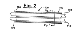
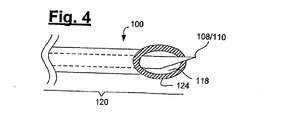
図1〜4には、治療部位にニードルのような複数の医療器具を送ることができる典型的な装置100が例示されている。治療部位に送られると、医療器具は、治療部位への薬剤の注入といった指定の機能を実施することが可能になる。装置100には、第1の内腔104と第2の内腔106が貫通しているカテーテル本体102が含まれている。第1の内腔104は、第1の器具108を収容するように構成され、第2の内腔106は、第2の器具110を収容するように構成されている。カテーテル本体102には、その近位部分122に近位ハンドル112も結合されている。近位ハンドル112には、第1の器具108を制御するように構成された第1の制御機構114と、第2の器具110を制御するように構成された第2の制御機構116が含まれている。カテーテル本体102の遠位部分120には、送り経路118が設けられている。送り経路118は、カテーテル本体102の遠位先端124で第1の器具108と第2の器具110を個別に導入できるように構成されている。
1-4 illustrate an
実施形態の1つでは、第1の器具108と第2の器具110の両方が、同時に送り経路118に進入することはできない。実施形態の1つでは、第1の器具108と第2の器具110を順次導入すると、第1の器具108と第2の器具110の個別導入を実現することが可能になる。1回につき、送り経路118を通って伸ばすのが、第1の器具108または第2の器具110の一方だけである場合に、第1の器具108と第2の器具110を順次導入することが可能になる。
In one embodiment, both the
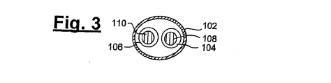
実施形態の1つでは、第1の内腔104と第2の内腔106は、カテーテル本体102の大部分にわたって、カテーテル本体102内の2つの独立した内腔として延びている(図2〜3)。第1の内腔104と第2の内腔106は、カテーテル本体102の遠位セクション120において、末端となり、収束し、送り経路118と呼ばれる単一内腔の管状セクションに統合される(図4)。第1の器具108は、第1の内腔104内を別個に進み、第2の器具110は、第2の内腔106内を別個に進む。しかし、器具108、110が、カテーテル本体の遠位セクション120で送り経路118に達すると、器具108または110の一方だけが、送られるか、または、送り経路118に沿って別様に伸ばされ、遠位先端124から突き出るように制御される。
In one embodiment, the
実施形態の1つでは、送り状態中、使用されていない時、または、器具108または110が治療部位に送られる前、第1の器具108は第1の内腔104内にあり、第2の器具110は第2の内腔106内にある(図5)。各器具108または110を個別に導入し、送り、あるいは、伸ばすため、近位ハンドル112を操作して、1回に1つずつ、器具108または110を作動させて、遠位先端124から外に送り出す。例えば、近位ハンドル112は、第1の器具108に接続された第1の制御機構114(図1)によって、第1の器具108を押しやり、図6に示すように、第1の内腔104から送り経路118内に第1の器具108を進入させることができるように構成されている。第1の器具108が進められている間、第2の器具110は、静止状態にあり、進むことができない。送り経路118は、また、1回に1つずつ器具108または器具110の一方だけが進入し、突き出すことができるように構成されている。第1の器具108が送られ、回収する準備が整うと、第1の制御機構114を介して、近位ハンドル112が、送り経路118から第1の器具108を引っ込め、第1の内腔104に戻す。第1の器具108の送りが済むと、次に、第2の器具110が、第1の器具108を進めたのと同様のやり方で、第2の制御機構116を介して、やはり近位ハンドル112によって送られる。第2の器具110が進められている間、第1の器具108は、静止状態にあり、進むことができない。第2の器具110が送られ、回収の準備が整うと、第2の制御機構116を介して、近位ハンドル112が、送り経路118から第2の器具110を引っ込め、第2の内腔106に戻す。
In one embodiment, the
実施形態の1つでは、第1の制御機構114は、第1の器具108に結合または接着されていて、近位ハンドル112に沿って第1の制御機構114をスライドさせると、それに対応して、カテーテル本体102内において第1の器具108を伸ばすか/進めるか、または、引っ込めることができるようになっている。同様に、第2の制御機構116は、第2の器具110に結合または接着されていて、近位ハンドル112に沿って第2の制御機構116をスライドさせると、それに対応して、カテーテル本体102内で第2の器具110を伸ばすか/進めるか、または、引っ込めることができるようになっている。近位ハンドル112には、第1の器具108と第2の器具110をそれぞれ操作するため、第1の制御機構114と第2の制御機構116がスライドするトラック(不図示)を含んでいてもよい。制御機構114、116にバネ荷重をかけて、治療剤が送られると、器具を自動的に引っ込めることができるようにすることが可能である。
In one embodiment, the
実施形態の1つでは、近位ハンドル112にインジケータ134とインジケータ136が含まれていて(図1)、各インジケータは、それぞれ、制御機構114、116のストッパとして機能し、カテーテル本体102からの器具108または106の伸長距離を制御するようになっている。制御機構114は、インジケータ134を通り越して移動するのが阻止され、従って、器具108は、所定の、インジケータ134によって指示される距離よりも遠位まで伸びることが阻止される。同様に、制御機構116は、インジケータ136を通り越して移動するのが阻止され、従って、器具110は所定の、インジケータ136によって指示される距離よりも遠位まで伸びることが阻止される。インジケータ134、136は、カテーテル本体102から、及び/または、治療部位内に、及び/または、治療部位に達するように、器具108、110を伸ばすべき所定の伸長距離に従って、近位ハンドル112に配置することが可能である。インジケータ134、136は、治療部位に対する不必要な損傷または穿刺を阻止するので、インジケータ134、136によって得られる機能は、器具108、110が尖った先を備えることが可能なニードルの場合に、とりわけ有効である。従って、インジケータ134、136は、器具108、110の伸長をそれぞれ制御する。
In one embodiment, the
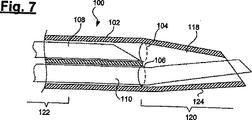
実施形態の1つでは、カテーテル本体102は、治療部位への進入または穿刺を容易にするため先が斜めになった遠位先端124で終わっている。実施形態の1つでは、遠位先端124は治療部位に貫入される。器具108、110は、それぞれ、生物剤成分を充填したニードルとすることが可能である。図5に示すように、送り中、器具108は引っ込み位置にあって、第1の内腔104内に収まっており、器具110も引っ込み位置にあって、第2の内腔106内に収まっている。送りの準備が整うと、1回につき1つのニードルが治療部位内に送り込まれる。図6に示すように、第1の器具108を遠位先端124から所定の距離だけ突き出す。器具108は、図6に示すように先が斜めになっている。器具108内の生物剤成分が治療部位に注入される。注入後、器具108は、図7に示すように第1の内腔104内に引き戻される。次に、図7に示すように、器具110を遠位先端124から所定の距離だけ突き出す。器具110内の生物剤成分が治療部位に注入される。
In one embodiment, the
実施形態の1つでは、送り経路118は、器具108または110の一方がその中を自由に移動するのにちょうど十分な公差の内径を有している。例えば、送り経路の内径または内側の寸法は、器具108、110を組み合わせた外径または外側の寸法より小さい。従って、1回につき、送り経路118を通ってスライド自在に伸びることができるのは、器具108または110の一方だけである。カテーテル本体102のテーパ状端部(カテーテル本体102の遠位部分122がテーパ状である)には、送り経路118を設けることが可能であり、送り経路118の外径がカテーテル本体102の残りの部分より細くなるようにすることが可能である。実施形態の1つでは、遠位先端124におけるカテーテル本体102の壁厚は、カテーテル本体102の残りの部分の壁厚より厚い。従って、遠位先端124の内腔(送り経路118)は、器具108または110の一方だけしか進入できないように、より細くなっている。
In one embodiment, the
各器具108または110は、任意の特定方向に合わせた向きとするか、あるいは、互いに対して及び/または遠位先端124に対して予め決めた方向に固定することが可能である。実施形態の1つでは、器具108、110の方向または向きは、送り前に、近位ハンドル112によって制御される。器具108、110は、それぞれ、特定の向きをなすように向けられ、さらに、対応する内腔104、106内に配置された後で、その向きに固定することが可能である。従って、実施形態の1つでは、器具108、110を進めるか、引き戻すことはできるが、回転させることはできない。代替案として、近位ハンドル112は、送り中、器具108、110の方向または向きを調整できるように構成することが可能であり、例えば、第1の制御機構114と第2の制御機構116に、それぞれ、器具108または110を特定の方向または向きになるように回転させるための機構を設けることが可能である。
Each
実施形態の1つでは、送り経路118と遠位先端124は、治療部位の1つの局所または1つの標的まで器具108、110を導くように構成されているので、器具108、110を、この特定の1つの局所または1つの標的位置に対して突き出すことが可能である。望ましい実施形態では、送り経路118と遠位先端124は、順次送られる場合でも、器具108、110の両方にほぼ同じ送り部位に対するアライメント及び方向づけを施すのに役立つ。こうした実施形態の場合、特定の治療部位で混合すべき2つ以上の異なる薬剤を、送られるまで、別々に保つことが可能である。薬剤は、送り部位についた時、治療部位のほぼ同じ局所に送られるようにすることが可能である。これによって、治療部位に薬剤を送り込み、最適な反応をもたらす効率の良い方法が可能になる。理解すべきは、装置100は、本明細書において上述のように注入を行うニードルに加えて、他の医療器具の送りにも役立つという点である。
In one embodiment, the
実施形態の1つでは、送り経路118の内壁が、送り経路118を通る器具108または110の移動を促進するため、滑らかな材料(不図示)によって裏打ちされている。裏打ちは、器具108または110に存在する可能性のある尖った先によって簡単には損傷を受けることのない材料から構成することが可能である。
In one embodiment, the inner wall of the
実施形態の1つでは、カテーテル本体102は、2つ以上の個別管(例えば、ハイポチューブまたはステンレス鋼ハイポチューブ)を溶接またはハンダ付けすることによって形成される。第1の内腔104と第2の内腔106も、ポリマ、コポリマ、ポリアミド、ポリオレフィン、ポリウレタン、ニチノール等のような任意の適合材料によって製造することが可能である。管または内腔を備える構造部材の構造は、当該技術において既知のところである。図8に示すように、カテーテル本体102の形成に利用される管140、142が設けられている。管140、142のそれぞれには、内腔144、146がそれぞれ貫通している。管140、142のそれぞれには、さらに、徐々にテーパ状に研削された端部148、150がそれぞれ含まれている。徐々にテーパ状に研削された端部148、150は、図9A〜9Bに示すように、これらの端部がやや半開きの管を形成するように、遠位端において管140、142のそれぞれを切削することによって形成される。カテーテル本体102は、従って、図10〜11に示すように、管140、142を溶接するか、ハンダ付けするか、または、別様に結合することによって形成される。管140、142は、徐々にテーパ状に研削された端部148、150において、溶接されるか、ハンダ付けされるか、または、結合されて、送り経路118を形成する。
In one embodiment, the
管140、142が溶接されるか、ハンダ付けされるか、または、結合されると、カテーテル本体102が形成される。実施形態の1つでは、カテーテル本体102は、近位領域122における双対内腔構造(2つの内腔144、146によって形成される)から、徐々にテーパ状に研削された2つの端部148、150を結合することによって形成された単一内腔の遠位領域120に変わる構造を有している。カテーテル本体102の遠位先端124は、図10に示すように、治療部位への進入を容易にするため、先が斜めになるように研削することが可能である。カテーテル本体102は、第1の内腔104と第2の内腔106が、それぞれ管140、142から形成される、Y字形状にすることが可能である。第1の内腔104と第2の内腔106が、遠位領域120で送り経路118に収束する2つの独立したトラックに配置される。
The
カテーテル本体102には、例えば、ガイドワイヤ、膨張バルーン、診断器具、及び/または、撮像器具を収容するための追加内腔(不図示)を含むことが可能である。カテーテル本体102には、ニードルのような追加器具のために、第1の内腔104と第2の内腔106と同様のより多くの内腔を含むことも可能である。場合によっては、特定の治療部位に複数薬剤を注入するため、複数ニードル(2つ以上の)が必要になることもある。実施形態の1つでは、カテーテル本体102のいくつかの内腔が、前述のように1つの経路(例えば、送り経路118)に収束ことになる。
The
実施形態の1つにおいて、各器具108、110の近位端には、器具への、最終的には、治療部位への薬剤の送りにそれぞれ対応するためのアダプタ160、162がある(図1)。アダプタ160、162は、それぞれ、一般に、それぞれのニードルに薬剤を注入できるようにするために用いられる、成形雌ルーアー・ハウジングとすることが可能である。
In one embodiment, there is an
上述のような実施形態は、患者の1つ以上の位置または部分に生体腐食性及び/または生体適合性ゲルを送り込むのに適している。例えば、アルギン酸と塩化カルシウムの結合(混合、接触等)によって形成されるゲル。典型的な例としては、アダプタ160における1立方センチメートルの注入器によって、本例の場合ニードルである器具108を介して、3.5%のアルギン酸塩溶液を送り込むことが可能である。直前または直後に、アダプタ162における1立方センチメートルの注入器によって、やはり、本例の場合ニードルである器具110を介して、塩化カルシウムの溶液を送り込むことが可能である。治療部位でアルギン酸塩と塩化カルシウムを合わせると、材料が結合(混合、接触)して、生体腐食性ゲルを形成する。心臓血管治療法に用いられる適量の2つの材料ゲル成分の一例は、約200マイクロリットルのアルギン酸塩溶液と1ミリリットルの塩化カルシウムである。余分な塩化カルシウムは、食塩水として患者の内部を洗い流すことが可能である。留意すべきは、薬剤は順次または同時に注入することができるという点である。
Embodiments as described above are suitable for delivering bioerodible and / or biocompatible gels to one or more locations or portions of a patient. For example, a gel formed by binding (mixing, contact, etc.) of alginic acid and calcium chloride. As a typical example, a one cubic centimeter syringe in
代替実施形態では、器具108、110の移動をそれぞれ制御するため、第1の制御機構114と第2の制御機構116の両方を含むか、組み込んだ近位ハンドル112を備える代わりに、器具108、110のそれぞれのために、それぞれ、制御機構を含む独立した1つの近位制御器具を設けることが可能である。
In an alternative embodiment, instead of having a
もう1つの実施形態(図12〜16)は、近位セクション222、遠位セクション220、及び、貫通する少なくとも第1の内腔204と第2の内腔206を備えるカテーテル本体202を含む装置200に関するものである(図12A〜12B、15)。第1の内腔204は、第1の器具208を収容するように構成され、第2の内腔206は、第2の器具210を収容するように構成されている。実施形態の1つでは、第1の器具208と第2の器具210は、治療部位に1つまたは複数の薬剤を送ることが可能なニードルである。もちろん、器具208、210は、前述のように他の器具とすることも可能である。近位セクション222において、第1の内腔204と第2の内腔206は、カテーテル本体202内を延びる2つの平行管のように互いに隣接して配置される(図14〜15)。遠位セクション220において、第1の内腔204と第2の内腔206は、やはり互いに隣接して配置されるが、内腔は一緒に8字形の断面を形成する(図15〜16)。従って、第1の内腔204と第2の内腔206は、各内腔がもう一方の内腔と隣接するセクションを備え、このセクションにおいて、内腔間に分割壁がなくなるように、縦方向に隣接して並列に配置されるか、あるいは、互いに隣接し、極めて近接して配置される(図16の断面図参照)。第1の内腔204と第2の内腔206は、一緒になって、断面形状が数字の8に似た断面形状を備える1つの内腔を形成することが可能である。カテーテル本体202は、ガイドワイヤまたは撮像器具のような他の器具を収容するための他の内腔を備えることが可能である。
Another embodiment (FIGS. 12-16) includes an
実施形態の1つでは、カテーテル本体202は、複数の内腔がカテーテル本体202の全長にわたって延びる管構造を有している。この実施形態の場合、カテーテル本体202の近位端にアダプタ280が結合される(図12A)。アダプタ280には、少なくとも2つのポート282、284が含まれており、ポート282、284は、それぞれ、内腔204、206の一方に通じている。実施形態の1つでは、器具208、210は、それぞれポート282、284に挿入され、それぞれの第1の内腔204と第2の内腔206に送り込まれる。アダプタ280には、通気、追加器具の挿入、または、他の目的に利用可能な追加ポート289も含まれている。
In one embodiment, the
実施形態の1つでは、アダプタ280は、カテーテル本体202の近位端に結合された近位制御ハンドルとなるように構成される。制御ハンドルは、第1の器具208を制御するように構成された第1の制御機構214と、第2の器具210を制御するように構成された第2の制御機構216を結合する。第1の制御機構214は、さらに、ある特定の向きまたは方向に第1の器具208を作動させ、回転させ、あるいは、伸ばすことができるように、第1の器具208に結合されるかまたは取り付けられている。第1の内腔204は、その中で第1の器具208を回転させ、かつ、そこから伸ばすことができるようなサイズが付与されている。同様に、第2の制御機構216は、さらに、ある特定の向きまたは方向に第2の器具210を作動させ、回転させ、あるいは、伸ばすことができるように、第2の器具210に結合されるかまたは取り付けられている。第2の内腔206は、やはり、その中で第2の器具210を回転させ、かつ、そこから伸ばすことができるようなサイズが付与されている。
In one embodiment,
実施形態の1つでは、第1の器具208の回転を制御するため、第1の制御機構214には、インジケータ291とインジケータ292を備えた回転ノブ288が設けられている。第1の制御機構214には、インジケータ286とインジケータ287を備えた固定ノブ298も設けられている。回転ノブ288を回転すなわち旋回させると、第1の器具208がそれに応じて回転すなわち旋回する。インジケータ291、292は、インジケータ286、287と連係して、第1の器具208の向きをオペレータに指示する働きをする。例えば、第1の器具208を回転させるため、回転ノブ288を旋回すなわち回転させている間、インジケータ291、287が、第1の器具208の回転を制限するように整列し、インジケータ292は、インジケータ286と共に、同様の機能を果たすように製鉄する。インジケータが整列すると、オペレータには、回転中の第1の器具208の位置が知らされる。インジケータ291、287とインジケータ292、286は、従って、第1の器具208の向きを指示するだけではなく、第1の器具208の過度の回転を制限する働きをも果たす。インジケータを用いると、第1の器具208は、簡単には過度回転しなくなり、その回転は、回転ノブ288によって制御できる。
In one embodiment, the
同様に、実施形態の1つでは、第2の器具210の回転を制御するため、第2の制御機構216には、インジケータ293とインジケータ294を備えた回転ノブ290が設けられている。第2の制御機構216には、インジケータ276とインジケータ277を備えた固定ノブ299も設けられている。回転ノブ290を回転すなわち旋回させると、第2の器具210がそれに応じて回転すなわち旋回する。インジケータ294、293は、インジケータ277、276と連係して、第2の器具210の向きをオペレータに指示する働きをする。例えば、第2の器具210を回転させるため、回転ノブ290を旋回すなわち回転させている間、インジケータ293、276が、第2の器具210の回転を制限するように整列し、インジケータ294は、インジケータ277と共に、同様の機能を果たすように整列する。インジケータが整列すると、オペレータには、回転中の第2の器具210の位置が知らされる。インジケータ293、276とインジケータ294、277は、従って、第2の器具210の向きを指示するだけではなく、第2の器具210の過度の回転を制限する働きをも果たす。インジケータを用いると、第2の器具210は、簡単には過度回転しなくなり、その回転は、回転ノブ290によって制御可能になる。
Similarly, in one embodiment, the
図13には、送り装置200に挿入して、治療部位まで送ることが可能な器具208、210の典型的な実施形態が例示されている。実施形態の1つでは、器具208、210は、それぞれ、治療部位に1つまたは複数の薬剤を注入することが可能なニードルである。実施形態の1つでは、各器具208、210の近位端には、それぞれ、器具への、最終的には治療部位への薬剤の送りに対応するためのアダプタ260、262がある。アダプタ260、262は、それぞれ、ニードルに薬剤を注入できるよう一般に用いられる成形雌ルーアー・ハウジングとすることが可能である。実施形態の1つでは、第1の器具208は、ポート282からアダプタ280に挿入されて、カテーテル本体202の内腔204に送り込まれる。第2の器具210は、ポート284からアダプタ280に挿入されて、カテーテル本体202の内腔206に送り込まれる。
FIG. 13 illustrates an exemplary embodiment of
実施形態の1つでは、送り装置200は、治療部位301に生物剤成分を送るために利用される。この実施形態の場合、第1の器具208は第1のニードル308であり、第2の器具210は第2のニードル310であるが、これらは、治療部位301で混合すると所望の生物剤成分を形成する薬剤を治療部位301に注入するために用いられる(図17〜22)。実施形態の1つでは、生物剤成分には、第1の薬剤318と第2の薬剤320が含まれる。第1の薬剤318は、第1のニードル308内に保有され、第2の薬剤320は第2のニードル310内に保有される。第1の注入ニードル308と第2の注入ニードル310は、それぞれ、一般にニードルに見られる斜めになった先(それぞれ、312、314)を備えている。ある適用例の1つでは、第1の薬剤318と第2の薬剤320は、混合されると、ゲル・マトリックスを形成する。従って、治療部位301への注入前に、2つの薬剤を混合させないのが望ましい。一般に、細いニードルの内腔を介してゲル成分を注入するのはより困難である。さらに、一方の薬剤をもう一方の薬剤に誤って注入すると、ニードル内で閉塞を生じる可能性があるので、治療部位につくまで、2つの薬剤を完全に分離した状態に保つのが望ましい。混合を目的として2つの薬剤を確実に同じ局所に注入し、かつ、隣接するニードル内腔への一方の薬剤の注入を防止するためには、注入を順次実施することが可能である。
In one embodiment, the
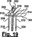
実施形態の1つでは、送り中、及び、治療部位301への最初の穿刺/進入時に、第1の注入ニードル308と第2の注入ニードル310は、図17に示すように、ニードル308、310の斜めになった遠位先端312、314が、一緒に1つの尖った先を形成するように位置決めされる。第1のニードル308と第2のニードル310は、互いに側面が押し付けられ、斜めになった先端が一緒に尖った先を形成するように回転させることが可能である。第1のニードル308と第2のニードル310は、互いに寄りかかる側面を備えることになる。実施形態の1つにおいて前述したように、遠位セクション220において、第1の内腔204と第2の内腔206は、一緒になって、送り経路を形成することが可能である。これによって、第1のニードル308と第2のニードル310は、互いに寄りかかることが可能になる。遠位先端312と遠位先端314の間に中心線316が形成される。中心線316は、2つのニードル308、310の接触線とみなすことが可能である。この時点で、斜めになった遠位先端312の遠位開口328は中心線とは別方向に向くことになる。同様に、斜めになった遠位先端314の遠位開口330も中心線316とは別方向に向くことになる。
In one embodiment, during delivery and upon first puncture / entry to
次に、第1の薬剤318または第2の薬剤320が治療部位301に注入される。一例では、図18〜19に示すように、最初に第2の薬剤320が注入され、続いて第1の薬剤318が注入される。図18の場合、第2の注入ニードル310から治療部位301に第2の薬剤320を注入するため、注入ニードル310を回転させて(第1の注入ニードル308が静止している間)、ニードル遠位開口330が中心線316の方を向くようにする。次に、治療部位301に第2の薬剤320が注入される。第1の注入ニードル308は、まだ、その遠位開口328が中心線316とは別方向に向いているので、第2の薬剤320は第1の注入ニードル308への進入を阻止される。2つの薬剤は、従って、治療部位301に注入されるまで分離した状態に保たれる。
Next, the
次に、第1の注入が済むと、第2に注入ニードル310を回転させて、図19に示すように、その斜めになった遠位開口330が中心線316とは別方向に向くようにする。第2の注入ニードル310は回転させられて、その初期状態に戻される。次に、第1の注入ニードル308を回転させて、図19に示すように、その斜めになった遠位開口328が中心線316の方を向くようにする。上記と同様に、第1の注入ニードル308が回転している間、第2の注入ニードル310は静止している。次に、治療部位301において第2の薬剤320が注入されたのとほぼ同じ局所に、第1の薬剤318が注入される。注入圧によって、2つの薬剤が混合し、こうした混合によって、治療部位にゲル・マトリックスを形成する治療反応が開始される。第1の薬剤318を送る前に、第2のニードル310を回転させて、その初期状態に戻すことは必要でない場合もある。例えば、図18に示すように、第2の薬剤320を注入した後、第1のニードル308を回転させ、その斜めになった遠位開口328が中心線の方を向くようにして、第1の薬剤318が注入される。両方のニードルとも、回転させて、その初期送り状態に戻すことなく、引き戻すことが可能である。
Next, when the first injection is completed, secondly, the
もう1つの実施形態の場合、最初に第1の薬剤318が治療部位に注入され、続いて第2の薬剤320が注入される。既述のプロセスが逆になる。従って、第1の注入ニードル308を回転させて、中心線の方を向くようにし、第1の薬剤318が注入される。第1の注入ニードル308は、回転させられて、初期位置に戻される。次に、第2の注入ニードル310を回転させて、中心線の方を向くようにし、第2の薬剤320が注入される。
In another embodiment,
留意すべきは、2つの注入ニードル308、310は、例えば、互いに向かい合うか、あるいは、それらの遠位開口に対して互いに180度の角度をなすといったように、互いにある角度をなすように回転させることができるという点である。
It should be noted that the two
実施形態の1つでは、送り装置200を異なる治療位置まで移動させて、さらなる注入のため、この注入プロセスが繰り返される。
In one embodiment, the
実施形態によっては、注入部位301に薬剤が同時に注入される場合もある。図20に例示のように、図17に示す最初の進入後、第1の注入ニードル308と第2の注入ニードル310は、遠位開口328、320が同じ方向を向くように回転させられる。次に、第1の薬剤318と第2の薬剤320が、一斉にまたは同時に治療部位301に注入される。図21に例示のように、もう1つの例では、図17に示す最初の進入後、第1の注入ニードル308と第2の注入ニードル310は、遠位開口328、320が互いに向き合うように回転させられる。次に、第1の薬剤318と第2の薬剤320が、一斉にまたは同時に治療部位301に注入される。
In some embodiments, drugs may be injected into the
さらにもう1つの実施形態では、第1の注入ニードル308と第2の注入ニードル310は、図22に例示のように、一方のニードルがもう一方のニードルの上に重なるように位置決めされる。例えば、図22に示すように、第2の注入ニードル310は、第1の注入ニードル308の上に重なるように位置決めされる。ニードルは、治療部位301に進入しやすくするため、やはり尖った先を形成するように位置決めされる。この構成の場合、ニードルの向きは制限されるか、または、固定される。従って、進入点から注入点まで、治療部位301に生じる外傷は最小限に抑えられる。
In yet another embodiment, the
他の実施形態の場合、2つのニードルの代わりに、3つ以上のニードルを設けることが可能である。より多くのニードルを用いる場合、ニードルの遠位先端の尖った先を維持するため、ニードルの直径をより小さくすべきである。さらに、送り装置200に収容される器具の全てが同じである必要はなく、例えば、全ての器具がニードルとは限らない。送り装置200を利用して、さまざまな器具の組合せを治療部位まで送ることができる。
In other embodiments, it is possible to provide more than two needles instead of two needles. If more needles are used, the needle diameter should be smaller to maintain the sharp tip of the distal tip of the needle. Furthermore, it is not necessary for all of the instruments accommodated in the
本明細書の実施形態のどれにおいても、さらに、治療部位まで送られるニードル内に収められた薬剤の固着を防ぐため、各ニードルにコーティングを施すことが可能である。留意すべきは、治療部位に注入される薬剤が、前述のように混合を必要とする種類である必要はないという点である。そうではなく、薬剤は、互いの近くに送る必要のある、治療効果の異なる成分とすることが可能である。 In any of the embodiments herein, each needle can be coated to prevent sticking of the drug contained within the needle that is delivered to the treatment site. It should be noted that the drug injected into the treatment site need not be of the type that requires mixing as described above. Instead, the drugs can be components with different therapeutic effects that need to be delivered close to each other.
図23〜26には、1つの治療部位への複数の注入または複数器具の送りに利用可能な器具の他の典型的な実施形態が例示されている。図27には、図23〜26に示す器具に関連して利用可能な典型的な送り装置400が例示されている。これらの実施形態では、回転可能な器具またはニードルを備える代わりに、所望の向きをなすように、器具またはニードルを溶接することが可能である。これらの器具の送りも、同時に、または、オプションにより順次実施することが可能である。
23-26 illustrate other exemplary embodiments of devices that can be used for multiple injections or multiple device delivery to a treatment site. FIG. 27 illustrates an
送り装置400(図27)は、複数の器具が、接着されるか、溶接されるか、または、別の方法で互いに取り付けられ、カテーテル本体の内腔の1つに収容されるという点を除くと、前述の装置200と同様である。装置400には、内腔403が貫通するカテーテル本体402が含まれている。カテーテル本体402の近位端には、近位アダプタ480が結合されている。近位アダプタ480には、装置200または100においての前述と同様に、装置400内の器具を個別に制御するための他の制御コンポーネントまたはハンドルを含むことも可能である。アダプタ480には、第1のポート482と第2のポート484も含まれている。他の目的または他の器具のために、ポート486のような追加ポートを含むことも可能である。前述のように、第1の器具408は第1のポート482に挿入され、第2の器具410は第2のポート484に挿入される。アダプタ480のポイントより前では、器具408、410のそれぞれは分離した状態に保たれる。器具408、410のそれぞれの残りの部分(カテーテル本体402内の部分)は、図23〜26に示すように溶接または接着される。
The delivery device 400 (FIG. 27) except that multiple instruments are glued, welded, or otherwise attached to each other and housed in one of the lumens of the catheter body. This is the same as the
各器具がカテーテル本体内に設けられたそれ自体の内腔内で分離した状態に保たれる既述の実施形態とは異なり、図23〜27に示す実施形態の場合、器具は溶接または接着して、カテーテル本体402の内腔の1つに収容される。図23の場合、第1の器具408と第2の器具410を互いに接着して、器具束433、437、または、439が形成される。図27に示すように、器具束はカテーテル本体402のカテーテル内腔403に収容することが可能である。実施形態の1つでは、第1の器具408と第2の器具410は、それぞれ、薬剤を送るための内腔が貫通しているニードルである。第1の器具408には遠位開口428が含まれており、第2の器具410には遠位開口430が含まれている。遠位開口428、430は、それぞれ、斜めにすることが可能である。器具束は、従って、各内腔が分注すべき薬剤専用の複数内腔を備えたニードルに似ている。図23に示す実施形態の1つでは、器具束433には、器具408、410の各遠位開口428、430が、それぞれ、同じ方向に向くように、第1の器具408と第2の器具410が位置決めされている。実施形態の1つでは、器具束433には、尖った先435が1つだけしかないので、扱いやすく、治療部位における進入部位または穿刺部位の外傷が軽減される。
Unlike the previously described embodiments where each instrument is kept separate within its own lumen provided within the catheter body, in the embodiment shown in FIGS. 23-27, the instrument is welded or bonded. And accommodated in one of the lumens of the
図24の場合、第1の器具408と第2の器具410を互いに接着して、器具束437が形成される。図27に示すように、器具437はカテーテル本体402のカテーテル内腔403に収容されている。第1の器具408と第2の器具410は、それぞれ、薬剤を送るための内腔が貫通しているニードルである。第1の器具408には遠位開口428が含まれており、第2の器具410には遠位開口430が含まれている。器具437は、やはり、複数内腔を備えたニードルに似ている。第1の器具408と第2の器具410は、器具408、410の各遠位開口428、430が、それぞれ、同じ方向に向き、一方の器具がもう一方の器具の上に重なるように配置されている。図24に示すように、開口428を備える第1の器具408が、開口430を備える第2の器具410の上に重ねられている。実施形態の1つでは、器具437には、やはり、尖った先435が1つだけしかないので、扱いやすく、治療部位における進入部位または穿刺部位の外傷が軽減される。
In the case of FIG. 24, the
図25の場合、第1の器具408と第2の器具410を互いに接着して、器具束439が形成される。図27に示すように、器具439は、カテーテル本体402のカテーテル内腔403に収容される。第1の器具408と第2の器具410は、それぞれ、薬剤を送るための内腔が貫通しているニードルである。第1の器具408には遠位開口428が含まれており、第2の器具410には遠位開口430が含まれている。器具439は、やはり、複数内腔を備えたニードルに似ている。さらに、器具439は、複数の尖った先441を備えるニードルのようでもある。第1の器具408と第2の器具410は、器具408、410の各遠位開口428、430が、ある程度互いに向き合うように、及び/または、同じ方向に向くように位置決めされている。器具439の器具408、410の遠位開口428、430は、その間に治療部位を確保する。器具408、410がそれぞれニードルである実施形態の場合、治療部位に送るべき薬剤は、開口428と430の間で捕らえられるので、不要な分散が最小限に抑えられ、薬剤の物理的接触が促進されて、効率の良い混合が施される。図26には、第1の器具408と第2の器具410が異なる角度で位置決めされており、開口428、430が互いにちょうど向かい合うという点を除くと、図25の器具439と同様の器具が例示されている。
In the case of FIG. 25, the
器具がニードルの場合、前述のように第1の器具と第2の器具が互いに接着された実施形態では、いくつかの利点がある。ニードルを互いに接着することによって、治療部位に薬剤の複数の個別の送り込みを実施し、同時に、注入まで薬剤を分離した状態に保つことが可能になる。さらに、ニードルを互いに接着することによって、向きまたは回転が制限され、この結果、治療部位の外傷または傷害が低減する可能性がある。さらに、例えば、各ニードルから各薬剤を注入した後のニードルの回転が不要になるといったように、複数注入の実施に必要なステップが減少する。さらにまた、ニードルを束ねることによって、他の実施形態の場合には生じる可能性のあるギャップが最小限に抑えられ、その結果、薬剤の逆流が最小限にとどまることになる。 When the instrument is a needle, there are several advantages in embodiments where the first instrument and the second instrument are bonded together as described above. By adhering the needles together, it is possible to perform multiple individual delivery of the drug to the treatment site and at the same time keep the drug separated until injection. In addition, bonding the needles together limits the orientation or rotation, which can reduce trauma or injury at the treatment site. Furthermore, the steps required to perform multiple injections are reduced such that, for example, the rotation of the needles after each drug is injected from each needle is not necessary. Furthermore, bundling the needles minimizes gaps that may occur in other embodiments, resulting in minimal drug backflow.
図12〜27において上述のような実施形態は、患者の1つ以上の部位または部分に生体腐食性及び/または生体適合性ゲルを送り込むのに適している。例えば、アルギン酸と塩化カルシウムの結合(混合、接触等)によって形成されるゲル。典型的な例としては、1立方センチメートルの注入器によって、本例の場合ニードルである第1の器具208を介して、3.5%のアルギン酸塩溶液を送り込むことが可能である。1立方センチメートルの注入器によって、やはり、本例の場合ニードルである第2の器具210を介して、塩化カルシウムの溶液を送り込むことが可能である。治療部位でアルギン酸塩と塩化カルシウムを合わせると、材料が結合(混合、接触)して、生体腐食性ゲルを形成する。心臓血管治療法に用いられる適量の2つの材料ゲル成分の一例は、約200マイクロリットルのアルギン酸塩溶液と1ミリリットルの塩化カルシウムである。余分な塩化カルシウムは、食塩水として患者の内部を洗い流すことが可能である。留意すべきは、薬剤は同時にまたは順次注入することができるという点である。
The embodiments as described above in FIGS. 12-27 are suitable for delivering a bioerodible and / or biocompatible gel to one or more sites or portions of a patient. For example, a gel formed by binding (mixing, contact, etc.) of alginic acid and calcium chloride. As a typical example, a one cubic centimeter syringe can deliver a 3.5% alginate solution through the
図28には、ニードルのような器具に収容された薬剤を治療部位に注入することを含む典型的な器具の送り方法2800が例示されている。同じ方法を利用して、撮像器具、流量または圧力測定器具、または、患者から流体または物質を除去するために用いられる他の器具といった、注入を必要としない他の器具を送ることも可能である。方法2800の場合、ボックス2802において、第1のニードルと第2のニードルを収容したカテーテルが治療部位まで進められる。前述のように、第1のニードルには第1の薬剤が充填され、第2のニードルには第2の薬剤が充填されている。ボックス2804では、治療部位において、カテーテルの遠位先端から第1のニードルと第2のニードルが順次突き出される。1回につき突き出されるのは、第1のニードルまたは第2のニードルの一方だけである。ボックス2806では、第1の薬剤と第2の薬剤が治療部位に順次注入される。例えば、第1の薬剤を注入するため、第1のニードルが突き出されるが、第2のニードルは突き出されない。第1の薬剤は治療部位に注入される。第1の薬剤の注入が済むと、第1のニードルが引っ込められ、第2のニードルが突き出される。次に、第2の薬剤が治療部位に注入される。
FIG. 28 illustrates an exemplary
実施形態の1つでは、方法2800に用いられるカテーテルは、近位セクション、遠位セクション、及び、それを貫通する少なくとも第1の内腔と第2の内腔を備えている。第1のニードルは第1の内腔に挿入され、第2のニードルは第2の内腔に挿入される。カテーテルには、第1のニードルを作動させるように構成された第1の制御機構と、第2のニードルを作動させるように構成された第2の制御機構を備えた制御ハンドルが結合されている。カテーテルの遠位セクションには、1回に1つ、第1のニードルと第2のニードルを個別に導入できるように構成された送り経路が含まれている。
In one embodiment, the catheter used in
図29には、ニードルのような器具に収容された薬剤を治療部位に注入することを含む典型的な器具の送り方法2900が例示されている。方法2900の場合、ボックス2902において、第1のニードルと第2のニードルを収容したカテーテルが治療部位まで進められる。前述のように、第1のニードルには第1の薬剤が充填され、第2のニードルには第2の薬剤が充填されている。ボックス2904では、第1のニードルと第2のニードルが、遠位セクションにおいて一緒に鋭い先を形成するように配置される。ボックス2906では、治療部位に穿刺が行われ、カテーテル本体の遠位先端から第1のニードルと第2のニードルが送られる。ニードルの送りには、ニードル内の薬剤を治療部位に順次または同時に注入するステップも含まれる。
FIG. 29 illustrates an exemplary
実施形態の1つでは、第1の薬剤と第2の薬剤は順次送られ、1回につき治療部位に薬剤を注入するのは第1のニードルまたは第2のニードルの一方だけである。実施形態の1つでは、送り前に、第1のニードルの遠位開口と第2のニードルの遠位開口が、第1のニードルと第2のニードルの間の中心線とは別方向に向くように位置決めされる。次に、第2のニードルが静止している間に、第1のニードルを回転させて、第1のニードルの遠位開口が中心線の方を向くようにする。次に、第1の薬剤が治療部位に注入される。第1の薬剤の注入が済むと、第1のニードルを回転させて、戻すか、あるいは、第1のニードルの遠位開口が中心線とは別方向に向くように回転させる。次に、第1のニードルが静止している間に、第2のニードルを回転させて、第2のニードルの遠位開口が中心線の方を向くようにする。次に、第2の薬剤が治療部位に注入される。第2の薬剤の注入が済むと、第2のニードルを回転させて戻すか、あるいは、第2のニードルの遠位開口が中心線とは別方向に向くように回転させる。 In one embodiment, the first and second medications are delivered sequentially and only one of the first needle or the second needle is infused into the treatment site at a time. In one embodiment, prior to feeding, the distal opening of the first needle and the distal opening of the second needle face away from the center line between the first and second needles. Are positioned as follows. Next, while the second needle is stationary, the first needle is rotated so that the distal opening of the first needle faces the centerline. Next, the first drug is injected into the treatment site. When the injection of the first drug is completed, the first needle is rotated and returned, or the distal opening of the first needle is rotated in a direction different from the center line. Next, while the first needle is stationary, the second needle is rotated so that the distal opening of the second needle faces the centerline. Next, a second drug is injected into the treatment site. When the second drug has been injected, the second needle is rotated back or rotated so that the distal opening of the second needle faces away from the center line.
もう1つの実施形態では、第1の薬剤と第2の薬剤が治療部位に同時に送られる。実施形態の1つでは、送り前に、第1のニードルの遠位開口と第2のニードルの遠位開口が、第1のニードルと第2のニードルの間の中心線とは別方向に向くように位置決めされる。こうした位置決めによって、ニードルに1つの尖った先が与えられ、治療部位への容易な進入が促進される。次に、第1のニードルと第2のニードルを回転させて、第1のニードルと第2のニードルの遠位開口が中心線の方を向くようにする。次に、第1の薬剤と第2の薬剤が、治療部位において同時かつ個別に注入される。もう1つの実施形態の場合、第1のニードルと第2のニードルのそれぞれの遠位開口が互いに向かい合うようにするのではなく、遠位開口は治療部位に向かって同じ方向を向いている。次に、第1の薬剤と第2の薬剤は、治療部位において同時かつ個別に注入される。 In another embodiment, the first drug and the second drug are delivered simultaneously to the treatment site. In one embodiment, prior to feeding, the distal opening of the first needle and the distal opening of the second needle face away from the center line between the first and second needles. Are positioned as follows. Such positioning provides the needle with a sharp point and facilitates easy entry into the treatment site. Next, the first needle and the second needle are rotated so that the distal openings of the first needle and the second needle are directed toward the center line. Next, the first drug and the second drug are injected simultaneously and separately at the treatment site. In another embodiment, rather than having the distal openings of the first and second needles face each other, the distal openings are oriented in the same direction toward the treatment site. Next, the first drug and the second drug are injected simultaneously and separately at the treatment site.
図30には、ニードルのような器具に収容された薬剤を治療部位に注入することを含む典型的な器具の送り方法3000が例示されている。方法3000の場合、ボックス3002において、互いに接着された第1のニードルと第2のニードルを収容したカテーテルが治療部位まで進められる。第1のニードルと第2のニードルのそれぞれは、遠位開口と、それを貫通する内腔を備えている。治療部位において穿刺が行われる。第1の薬剤と第2の薬剤が、治療部位において同時かつ個別に注入される。実施形態の1つでは、第1のニードルと第2のニードルが互いに接着されて、第1のニードルと第2のニードルの両方の遠位開口を含む、1つの斜めになった先端が形成される。もう1つの実施形態では、第1のニードルと第2のニードルが互いに接着されて、第1のニードルの遠位開口と第2のニードルの遠位開口が向かい合う。
FIG. 30 illustrates an exemplary
図31Aには、治療部位に複数の器具(例えばニードル)を送ることが可能なカテーテル装置3100のさらにもう1つの実施形態が例示されている。前述のように、それぞれ薬剤を収めた複数のニードルを治療部位まで送ることが可能である。薬剤は治療部位に同時にまたは順次送ることが可能である。カテーテル装置3100の近位部分から遠位部分まで延びる1つの内腔だけに複数の器具を収容できるという点を除けば、カテーテル装置3100は、既述のカテーテル装置(例えば、100、200、400)と同様である。
FIG. 31A illustrates yet another embodiment of a
前述と同様に、装置3100には、器具を収容するための細長いカテーテル・シャフトまたは本体3102が含まれている。カテーテル・シャフト3102は、内腔3103が貫通している。内腔3103は、その中に配置すべき第1の器具3108(例えば、ニードル)と第2の器具3110(例えば、ニードル)を収容する。カテーテル・シャフト3102は、近位セクション3122と遠位セクション3120を備えており、内腔3103の遠位セクション3120は近位セクション3122よりも細い。実施形態の1つでは、内腔3103は遠位セクションがテーパ状になっているので、1回につき、それを通って突き出すことができるのは器具3108または3110の一方だけである。カテーテル3102の遠位セクション3122において、第1の器具3108と第2の器具3110の間にはギャップがないか、または、ほとんどギャップがない。代替実施形態では、カテーテル3102の内腔3103全体にわたって、第1の器具3108と第2の器具3110の間にはギャップがないか、または、ほとんどギャップがない。器具3108、3110は、互いに極めて近接して配置されているので、互いを隔てる壁はない。実施形態の1つでは、器具3108、3110は、互いに固定されるか、または、取り付けられているわけではなく、ただ単に並列に配置されているだけである。各器具は、もう一方に影響を及ぼすことなく回転することが可能である。
As before,
他の態様では、装置3100は、カテーテル本体3102の近位セクションにおける単一内腔を除けば、前述の装置100、200、及び、400と同様である。近位端において、同様の近位ハンドルまたは制御器具をカテーテル本体3102と結合して、器具3108、3110を個別に制御できるようにすることが可能である。実施形態の1つでは、前述と同様に、第1のポートが第1の器具3108と通じ、第2のポートが第2の器具3110と通じるように、近位アダプタが細長いシャフトに結合される。
In other aspects,
実施形態の1つでは、図31Bに示すように、内腔3103はカテーテル本体3102全体にわたる楕円形状の内腔である。内腔3103は、図16に示すのと同様の数字の8のような形状または断面を備えることも可能である。こうした場合、内腔3103の形成は、複数の内腔または管を統合するか、併合するか、または、溶接して、器具3108、3110を、それらの間を隔てる壁を設けずに収容できるように、内腔3103を形成することによって可能になる。
In one embodiment, the
実施形態の1つでは、遠位セクション3120において、内腔3103は、1回につき1つの器具だけを収容することしかできないように構成されている。従って、図31Aに示すように、遠位セクション3120において、1回につき、器具3108または3110だけしか内腔3103から突き出すことができない。内腔3103は、内腔3103の内側の寸法が器具3108と3110の両方を組み合わせた外側の寸法より小さくなるように、テーパ状にするかまたは細くすることが可能である。
In one embodiment, in the
代替実施形態の場合、遠位セクション3120において、内腔3103は、器具3108または3110の移動を制限するが、各器具の回転を可能にする楕円形状を有している。この実施形態の場合、遠位セクション3120は、一度に両方の器具3108、3110を収容することが可能である。
In an alternative embodiment, in the
本明細書で論考の実施形態は、いずれも、送りプロセス中、洗浄剤を供給して、その内部を洗浄することが可能である。注入した薬剤が逆流して、フローブロー(flow blow)になる(例えば、心室または血管に対する)のが問題である。ヘパリンのような薬剤で治療部位を洗浄すると、逆漏れした薬剤が血栓を形成するプロセスを阻止することができると考えられている。本発明の実施形態の器具は、カテーテルの1つまたは複数の内腔を洗浄できるように構成することが可能である。近位ハンドルの近位端でまたは近位ハンドルの一部として、内腔にアダプタを取り付けることが可能である(例えば、装置200のポート289を介してまたは装置400のポート486を介して)。注入中、及び/または、穿刺部位からニードルを引き抜いた直後の後続注入中、穿刺部位の辺りにヘパリン溶液を注入して、血栓の形成が阻止される。この注入内腔を利用して、例えば、穿刺部位の確認といった目的で、造影剤または他の薬剤を注入することも可能である。
Any of the embodiments discussed herein can be supplied with a cleaning agent to clean its interior during the feeding process. The problem is that the injected drug flows back into a flow blow (eg, to the ventricle or blood vessel). It is believed that cleaning the treatment site with a drug such as heparin can prevent the process of back-throwing drugs from forming a thrombus. The device of embodiments of the present invention can be configured to allow cleaning of one or more lumens of a catheter. An adapter can be attached to the lumen at the proximal end of the proximal handle or as part of the proximal handle (eg, via port 289 of
云うまでもないが、上記説明では、さまざまな実施形態の多くの特性及び利点が、さまざまな実施形態の構造及び機能の詳細と共に明らかにされたが、この開示は例証のためのものでしかない。さまざまな実施形態の範囲から逸脱することなく、とりわけ、諸部分の構造及び取り扱いの問題について、細部にわたって変更を加えることが可能である。 It goes without saying that while the above description has revealed many features and advantages of various embodiments, together with details of the structure and function of the various embodiments, this disclosure is for purposes of illustration only. . Without departing from the scope of the various embodiments, it is possible to make changes in detail, particularly with regard to the structure and handling issues of the parts.
100 送り装置、102 カテーテル本体、104 第1の内腔、106 第2の内腔、108 第1の器具、110 第2の器具、112 近位ハンドル、114 第1の制御機構、116 第2の制御機構、118 送り経路、120 カテーテル本体の遠位部分、124 カテーテル本体の遠位先端、134 インジケータ、136 インジケータ、140 管、142 管、144 内腔、146 内腔、148 テーパ状端部、150 テーパ状端部、160 アダプタ、162 アダプタ 100 first delivery device, 102 catheter body, 104 first lumen, 106 second lumen, 108 first instrument, 110 second instrument, 112 proximal handle, 114 first control mechanism, 116 second Control mechanism, 118 delivery path, 120 distal portion of the catheter body, 124 distal tip of the catheter body, 134 indicator, 136 indicator, 140 tube, 142 tube, 144 lumen, 146 lumen, 148 tapered end, 150 Tapered end, 160 adapter, 162 adapter
Claims (21)
前記カテーテル本体に結合された制御ハンドルであって、前記第1の器具の動きを制御するように構成された第1の制御機構と、第2の器具の動きを制御するように構成された第2の制御機構と、前記第1の器具の動く方向を制限しかつ前記第1の器具の向きを示す第1のインジケータと、そして前記第2の器具の動く方向を制限しかつ前記第2の器具の向きを示す第2のインジケータと、を含む制御ハンドルと、そして
前記カテーテル本体の遠位部分に設けられた送り経路であって、前記カテーテル本体の遠位先端から前記第1の器具と前記第2の器具の個別導入を可能にするように構成されている送り経路と
を含むことを特徴とする送り装置。A first lumen and a second lumen are pierced, the first lumen is configured to receive the first instrument, and the second lumen receives the second instrument A catheter body configured as follows:
A control handle coupled to the catheter body, the first control mechanism configured to control movement of the first instrument, and a first control mechanism configured to control movement of the second instrument. and second control mechanisms, the a first indicator indicating the direction of the first limiting vital said first instrument a direction of movement of the instrument, and the direction of the limit vital second of movement of the second instrument a second indicator indicating the orientation of the instrument, and a control handle including, and said a feed path which kicked set to a distal portion of the catheter body, said first instrument from the distal tip of the catheter body A feed path configured to allow individual introduction of the second instrument.
前記カテーテル本体に結合された制御ハンドルと、
を備え、
前記第1の内腔は第1の器具を収容するように構成され、前記第2の内腔は第2の器具を収容するように構成されており、前記第1の内腔と前記第2の内腔は互いに並列に配置されており、その際、前記カテーテル本体の前記遠位セクションには、前記第1の内腔と前記第2の内腔とを隔てる壁がなく、
前記制御ハンドルは前記第1の器具の動きを制御するように構成された第1の制御機構と、前記第2の器具の動きを制御するように構成された第2の制御機構と、前記第1の器具の動く方向を制限しかつ前記第1の器具の向きを示す第1のインジケータと前記第2の器具の動く方向を制限しかつ前記第2の器具の向きを示す第2のインジケータとを具備することを特徴とする送り装置。A catheter body comprising a proximal section, a distal section, and at least a first lumen and a second lumen therethrough;
A control handle coupled to the catheter body;
With
The first lumen is configured to receive a first instrument, and the second lumen is configured to receive a second instrument, the first lumen and the second Are disposed in parallel with each other, wherein the distal section of the catheter body has no wall separating the first lumen and the second lumen;
The control handle includes a first control mechanism configured to control movement of the first instrument, a second control mechanism configured to control movement of the second instrument, and the first control mechanism. A first indicator that limits the direction of movement of one instrument and indicates the orientation of the first instrument; and a second indicator that limits the direction of movement of the second instrument and indicates the orientation of the second instrument ; A feeding device comprising:
前記第1の内腔に通じる第1のポートと前記第2の内腔に通じる第2のポートを具備した、前記カテーテルの前記細長いシャフトの近位端に結合された近位アダプタと、
を備え、
前記第1の内腔は第1の器具を収容するように構成され、前記第2の内腔は第2の器具を収容するように構成され、前記カテーテルの遠位端のポートと前記第1と第2の内腔と通じている内腔は設けられた遠位セクションを備え、
前記近位アダプタは、回転ノブと、第1のインジケータ対とを具備する第1の制御機構を備え、第1の器具が前記第1の内腔に配置されて前記第1の制御機構に接続されたときには、前記回転ノブの回転によって前記第1の器具が回転すると共に前記第1の器具の向きを示す前記第1のインジケータ対が回転し、
前記近位アダプタは、回転ノブと、第2のインジケータ対とを具備する第2の制御機構をさらに備え、第2の器具が前記第2の内腔に配置されて前記第2の制御機構に接続されたときには、前記回転ノブの回転によって前記第2の器具が回転すると共に前記第2の器具の向きを示す第2のインジケータ対が回転する
ことを特徴とするカテーテル装置。A catheter comprising an elongate shaft through which a first lumen and a second lumen pass;
A proximal adapter coupled to a proximal end of the elongate shaft of the catheter, the proximal adapter comprising a first port leading to the first lumen and a second port leading to the second lumen;
With
The first lumen is configured to receive a first instrument, and the second lumen is configured to receive a second instrument, the distal end port of the catheter and the first A lumen in communication with the second lumen includes a distal section provided;
The proximal adapter comprises a first control mechanism comprising a rotation knob and a first indicator pair, and a first instrument is disposed in the first lumen and connected to the first control mechanism. When the rotation of the rotary knob, the first instrument is rotated and the first indicator pair indicating the orientation of the first instrument is rotated.
The proximal adapter further comprises a second control mechanism comprising a rotation knob and a second indicator pair, and a second instrument is disposed in the second lumen to connect to the second control mechanism. When connected, the catheter device is characterized in that the second instrument is rotated by the rotation of the rotary knob and the second indicator pair indicating the orientation of the second instrument is rotated.
前記第1の器具に通じる第1のポートと前記第2の器具に通じる第2のポートを具備した、前記カテーテルの前記細長いシャフトの近位端に結合された近位アダプタと、
を備え、
前記内腔の遠位セクションが前記内腔の近位セクションより細く、
前記近位アダプタは、第1のインジケータを具備する第1の制御機構を備え、前記第1の器具が前記第1の内腔に配置されたときには、前記第1のインジケータが前記第1の器具の向きを示し、
前記近位アダプタは、第2のインジケータを具備する第2の制御機構を備え、前記第2の器具が前記第2の内腔に配置されたときには、前記第2のインジケータが前記第2の器具の向きを示す
ことを特徴とするカテーテル装置。A catheter comprising an elongate shaft having a lumen therethrough for receiving a first instrument and a second instrument to be disposed therein;
A proximal adapter coupled to the proximal end of the elongate shaft of the catheter, comprising a first port leading to the first instrument and a second port leading to the second instrument;
With
The distal section of the lumen is narrower than the proximal section of the lumen;
The proximal adapter includes a first control mechanism that includes a first indicator, and when the first instrument is disposed in the first lumen, the first indicator is the first instrument. Indicate the direction of
The proximal adapter includes a second control mechanism that includes a second indicator, and when the second instrument is disposed in the second lumen, the second indicator is the second instrument. A catheter device characterized by indicating the orientation of the catheter.
Applications Claiming Priority (3)
| Application Number | Priority Date | Filing Date | Title |
|---|---|---|---|
| US11/112,546 | 2005-04-22 | ||
| US11/112,546 US9149602B2 (en) | 2005-04-22 | 2005-04-22 | Dual needle delivery system |
| PCT/US2006/013909 WO2006115811A1 (en) | 2005-04-22 | 2006-04-12 | A dual needle delivery system |
Publications (3)
| Publication Number | Publication Date |
|---|---|
| JP2008536625A JP2008536625A (en) | 2008-09-11 |
| JP2008536625A5 JP2008536625A5 (en) | 2009-06-04 |
| JP5086240B2 true JP5086240B2 (en) | 2012-11-28 |
Family
ID=36698998
Family Applications (1)
| Application Number | Title | Priority Date | Filing Date |
|---|---|---|---|
| JP2008507728A Expired - Fee Related JP5086240B2 (en) | 2005-04-22 | 2006-04-12 | Dual needle feeding system |
Country Status (4)
| Country | Link |
|---|---|
| US (2) | US9149602B2 (en) |
| EP (1) | EP1888159B1 (en) |
| JP (1) | JP5086240B2 (en) |
| WO (1) | WO2006115811A1 (en) |
Families Citing this family (44)
| Publication number | Priority date | Publication date | Assignee | Title |
|---|---|---|---|---|
| US8614768B2 (en) | 2002-03-18 | 2013-12-24 | Raytheon Company | Miniaturized imaging device including GRIN lens optically coupled to SSID |
| US8425539B2 (en) * | 2004-04-12 | 2013-04-23 | Xlumena, Inc. | Luminal structure anchoring devices and methods |
| US8328837B2 (en) | 2004-12-08 | 2012-12-11 | Xlumena, Inc. | Method and apparatus for performing needle guided interventions |
| US8784437B2 (en) | 2005-06-09 | 2014-07-22 | Xlumena, Inc. | Methods and devices for endosonography-guided fundoplexy |
| US8777967B2 (en) | 2005-06-09 | 2014-07-15 | Xlumena, Inc. | Methods and devices for anchoring to tissue |
| US8012096B2 (en) * | 2005-10-17 | 2011-09-06 | Cardiogenesis Corporation | Surgical device and method for performing combination revascularization and therapeutic substance delivery to tissue |
| US20080243080A1 (en) * | 2007-03-27 | 2008-10-02 | Chang David W | Method and apparatus for vascular access |
| US20080255520A1 (en) * | 2007-04-11 | 2008-10-16 | Henderson Thomas D | Multiple injection syringe holder |
| US7835074B2 (en) | 2007-06-05 | 2010-11-16 | Sterling Lc | Mini-scope for multi-directional imaging |
| US8454632B2 (en) | 2008-05-12 | 2013-06-04 | Xlumena, Inc. | Tissue anchor for securing tissue layers |
| US20090281379A1 (en) | 2008-05-12 | 2009-11-12 | Xlumena, Inc. | System and method for transluminal access |
| US8690762B2 (en) | 2008-06-18 | 2014-04-08 | Raytheon Company | Transparent endoscope head defining a focal length |
| WO2010014792A2 (en) | 2008-07-30 | 2010-02-04 | Sterling Lc | Method and device for incremental wavelength variation to analyze tissue |
| US9060704B2 (en) | 2008-11-04 | 2015-06-23 | Sarcos Lc | Method and device for wavelength shifted imaging |
| US9364259B2 (en) | 2009-04-21 | 2016-06-14 | Xlumena, Inc. | System and method for delivering expanding trocar through a sheath |
| WO2010138277A1 (en) | 2009-05-29 | 2010-12-02 | Xlumena, Inc. | Apparatus and method for deploying stent across adjacent tissue layers |
| WO2011011497A1 (en) * | 2009-07-21 | 2011-01-27 | North Richard B | Spinal cord stimulation lead anchor |
| US9661996B2 (en) | 2009-10-01 | 2017-05-30 | Sarcos Lc | Needle delivered imaging device |
| WO2011041730A2 (en) | 2009-10-01 | 2011-04-07 | Jacobsen Stephen C | Light diffusion apparatus |
| WO2011041720A2 (en) | 2009-10-01 | 2011-04-07 | Jacobsen Stephen C | Method and apparatus for manipulating movement of a micro-catheter |
| US9498271B2 (en) * | 2009-10-29 | 2016-11-22 | Cook Medical Technologies Llc | Coaxial needle cannula with distal spiral mixer and side ports for fluid injection |
| US8828028B2 (en) | 2009-11-03 | 2014-09-09 | Raytheon Company | Suture device and method for closing a planar opening |
| WO2011109288A1 (en) | 2010-03-01 | 2011-09-09 | Cook Medical Technologies, LLC | Thermo-chemical medical device for manipulation of tissue |
| JP2011255065A (en) * | 2010-06-11 | 2011-12-22 | Nipro Corp | Injection device |
| US10758262B2 (en) * | 2011-06-20 | 2020-09-01 | Medtronic, Inc. | Medical assemblies and methods for implantation of multiple medical leads through a single entry |
| US10952732B2 (en) | 2013-02-21 | 2021-03-23 | Boston Scientific Scimed Inc. | Devices and methods for forming an anastomosis |
| DE202013012853U1 (en) | 2012-05-17 | 2020-08-31 | Boston Scientific Scimed, Inc. | Devices for access over adjacent tissue layers |
| EP3027262A4 (en) * | 2013-07-29 | 2017-03-22 | Imricor Medical Systems, Inc. | Actively tracked medical devices |
| ES2651940T3 (en) * | 2014-07-02 | 2018-01-30 | Site Saver, Inc. | Venous access device |
| WO2016027502A1 (en) * | 2014-08-21 | 2016-02-25 | オリンパス株式会社 | Hard mirror set |
| US9981119B2 (en) * | 2014-10-29 | 2018-05-29 | Edwards Lifesciences Corporation | Bi-directional cannula |
| US20170273628A1 (en) * | 2016-03-24 | 2017-09-28 | C. R. Bard, Inc. | Catheter Assembly Including Transitioning Lumens |
| US11103276B2 (en) * | 2016-11-02 | 2021-08-31 | 510 Kardiac Devices, Inc. | Dual lumen dilator for use in transseptal punctures |
| US11096810B2 (en) * | 2017-11-29 | 2021-08-24 | Cook Medical Technologies Llc | Preloaded pusher tip for endografts |
| US11458250B2 (en) | 2018-05-31 | 2022-10-04 | Insulet Corporation | System and techniques for drug reservoir volume detection |
| EP3823692B1 (en) * | 2018-07-18 | 2024-09-18 | Insulet Corporation | Drug delivery insertion apparatuses and system |
| CN113825453A (en) * | 2019-05-17 | 2021-12-21 | 波士顿科学国际有限公司 | Medical imaging device and system |
| JP7484211B2 (en) | 2020-02-19 | 2024-05-16 | Toppanホールディングス株式会社 | Cell Transplantation Device |
| WO2022174133A1 (en) * | 2021-02-15 | 2022-08-18 | Medtronic, Inc. | Transseptal systems and methods |
| US11806000B2 (en) * | 2021-02-15 | 2023-11-07 | Medtronic, Inc. | Transseptal systems and methods |
| US11883616B2 (en) * | 2021-07-07 | 2024-01-30 | Mekal, LLC | Multi-lumen intravascular catheters with inner converging lumens for multiple guidewire control |
| US12090498B2 (en) | 2021-08-19 | 2024-09-17 | Insulet Corporation | Low-friction rolling plunger for a wearable drug delivery device |
| WO2023062522A1 (en) * | 2021-10-12 | 2023-04-20 | Spectrum Technologies, Llc | Device, system and method for cardiac valve repair |
| WO2024114922A1 (en) * | 2022-12-02 | 2024-06-06 | Clearstream Technologies Limited | A rotational atherectomy device |
Family Cites Families (272)
| Publication number | Priority date | Publication date | Assignee | Title |
|---|---|---|---|---|
| US3177543A (en) | 1962-11-14 | 1965-04-13 | Cecil D Fountain | Safety locking device |
| US3716058A (en) | 1970-07-17 | 1973-02-13 | Atlanta Res Inst | Barbed suture |
| US3804097A (en) * | 1972-12-14 | 1974-04-16 | P Rudie | Method of irrigating and treating an abcess |
| US4072146A (en) | 1976-09-08 | 1978-02-07 | Howes Randolph M | Venous catheter device |
| US4128100A (en) | 1976-10-08 | 1978-12-05 | Wendorff Erwin R | Suture |
| US4781186A (en) | 1984-05-30 | 1988-11-01 | Devices For Vascular Intervention, Inc. | Atherectomy device having a flexible housing |
| US4675004A (en) | 1985-04-16 | 1987-06-23 | Quinton Instrument Company | Dual-lumen fistula needle |
| US5061273A (en) | 1989-06-01 | 1991-10-29 | Yock Paul G | Angioplasty apparatus facilitating rapid exchanges |
| US5350395A (en) | 1986-04-15 | 1994-09-27 | Yock Paul G | Angioplasty apparatus facilitating rapid exchanges |
| US5040548A (en) | 1989-06-01 | 1991-08-20 | Yock Paul G | Angioplasty mehtod |
| US4719924A (en) | 1986-09-09 | 1988-01-19 | C. R. Bard, Inc. | Small diameter steerable guidewire with adjustable tip |
| JPH053053Y2 (en) | 1987-01-23 | 1993-01-26 | ||
| US4808156A (en) | 1987-03-09 | 1989-02-28 | Dean Consuelo M | Cannular instrument and method for inserting a cannular instrument into a vein |
| US5100418A (en) | 1987-05-14 | 1992-03-31 | Inbae Yoon | Suture tie device system and applicator therefor |
| US4920980A (en) | 1987-09-14 | 1990-05-01 | Cordis Corporation | Catheter with controllable tip |
| US4830023A (en) | 1987-11-27 | 1989-05-16 | Medi-Tech, Incorporated | Medical guidewire |
| US4886067A (en) | 1989-01-03 | 1989-12-12 | C. R. Bard, Inc. | Steerable guidewire with soft adjustable tip |
| US5163903A (en) | 1989-01-27 | 1992-11-17 | C. R. Bard, Inc. | Catheter exchange system with detachable luer fitting |
| US5431673A (en) | 1989-02-17 | 1995-07-11 | American Biomed, Inc. | Distal atherectomy catheter |
| US4994067A (en) | 1989-02-17 | 1991-02-19 | American Biomed, Inc. | Distal atherectomy catheter |
| US5728129A (en) | 1989-02-17 | 1998-03-17 | American Biomed, Inc. | Distal atherectomy catheter |
| US4927421A (en) | 1989-05-15 | 1990-05-22 | Marlowe Goble E | Process of endosteal fixation of a ligament |
| US4932962A (en) | 1989-05-16 | 1990-06-12 | Inbae Yoon | Suture devices particularly useful in endoscopic surgery and methods of suturing |
| US5129906A (en) | 1989-09-08 | 1992-07-14 | Linvatec Corporation | Bioabsorbable tack for joining bodily tissue and in vivo method and apparatus for deploying same |
| US5226909A (en) | 1989-09-12 | 1993-07-13 | Devices For Vascular Intervention, Inc. | Atherectomy device having helical blade and blade guide |
| US5254088A (en) | 1990-02-02 | 1993-10-19 | Ep Technologies, Inc. | Catheter steering mechanism |
| US5129902A (en) | 1990-04-20 | 1992-07-14 | Marlowe Goble E | Endosteal ligament retainer and process |
| US5171233A (en) | 1990-04-25 | 1992-12-15 | Microvena Corporation | Snare-type probe |
| US6117176A (en) | 1993-11-15 | 2000-09-12 | Applied Elastomerics, Inc. | Elastic-crystal gel |
| US5102421A (en) | 1990-06-14 | 1992-04-07 | Wm. E. Anpach, III | Suture anchor and method of forming |
| US5273527A (en) | 1992-05-12 | 1993-12-28 | Ovamed Corporation | Delivery catheter |
| US5100421A (en) | 1991-02-05 | 1992-03-31 | Cyprus Endosurgical Tools, Inc. | Christoudias curved needle suture assembly |
| US5219335A (en) * | 1991-05-23 | 1993-06-15 | Scimed Life Systems, Inc. | Intravascular device such as introducer sheath or balloon catheter or the like and methods for use thereof |
| US5116337A (en) | 1991-06-27 | 1992-05-26 | Johnson Lanny L | Fixation screw and method for ligament reconstruction |
| US5571215A (en) | 1993-02-22 | 1996-11-05 | Heartport, Inc. | Devices and methods for intracardiac procedures |
| US5234443A (en) | 1991-07-26 | 1993-08-10 | The Regents Of The University Of California | Endoscopic knot tying apparatus and methods |
| US5201598A (en) | 1991-07-31 | 1993-04-13 | Tehan Frank V | Attachment of cord to tube end using locking sleeve to permit easy cord replacement |
| US5141520A (en) | 1991-10-29 | 1992-08-25 | Marlowe Goble E | Harpoon suture anchor |
| US5242456A (en) | 1991-11-21 | 1993-09-07 | Kensey Nash Corporation | Apparatus and methods for clamping tissue and reflecting the same |
| US6001104A (en) | 1991-12-03 | 1999-12-14 | Boston Scientific Technology, Inc. | Bone anchor implantation device |
| US5423882A (en) | 1991-12-26 | 1995-06-13 | Cordis-Webster, Inc. | Catheter having electrode with annular recess and method of using same |
| US5156616A (en) | 1992-02-10 | 1992-10-20 | Meadows Bruce F | Apparatus and method for suture attachment |
| US5327905A (en) | 1992-02-14 | 1994-07-12 | Boaz Avitall | Biplanar deflectable catheter for arrhythmogenic tissue ablation |
| US5273533A (en) * | 1992-03-11 | 1993-12-28 | Care Medical Products, Inc. | Medical valve |
| US6770066B1 (en) | 1992-05-11 | 2004-08-03 | Ballard Medical Products | Multi-lumen endoscopic catheter |
| US5290244A (en) * | 1992-06-08 | 1994-03-01 | Dilip Moonka | Syringe and needle with guide wire for cannulation of central veins |
| US5352215A (en) * | 1992-08-26 | 1994-10-04 | Scimed Life Systems, Inc. | Y-adapter with a sideport radius |
| CA2100532C (en) | 1992-09-21 | 2004-04-20 | David T. Green | Device for applying a meniscal staple |
| US5972000A (en) | 1992-11-13 | 1999-10-26 | Influence Medical Technologies, Ltd. | Non-linear anchor inserter device and bone anchors |
| IL103737A (en) | 1992-11-13 | 1997-02-18 | Technion Res & Dev Foundation | Stapler device particularly useful in medical suturing |
| US5441483A (en) | 1992-11-16 | 1995-08-15 | Avitall; Boaz | Catheter deflection control |
| US5261889A (en) * | 1992-11-24 | 1993-11-16 | Boston Scientific Corporation | Injection therapy catheter |
| US6283127B1 (en) | 1992-12-03 | 2001-09-04 | Wesley D. Sterman | Devices and methods for intracardiac procedures |
| US5383260A (en) | 1992-12-11 | 1995-01-24 | Avery Dennison Corporation | Fastener clip including one or more fasteners adapted for attaching buttons to a garment or like material |
| US5495974A (en) | 1992-12-11 | 1996-03-05 | Avery Dennison Corporation | Fastener attaching tool |
| US5518162A (en) | 1992-12-11 | 1996-05-21 | Avery Dennison Corporation | Fastener attaching tool |
| US5613937A (en) | 1993-02-22 | 1997-03-25 | Heartport, Inc. | Method of retracting heart tissue in closed-chest heart surgery using endo-scopic retraction |
| US5728151A (en) | 1993-02-22 | 1998-03-17 | Heartport, Inc. | Intercostal access devices for less-invasive cardiovascular surgery |
| US6161543A (en) | 1993-02-22 | 2000-12-19 | Epicor, Inc. | Methods of epicardial ablation for creating a lesion around the pulmonary veins |
| US5374275A (en) | 1993-03-25 | 1994-12-20 | Synvasive Technology, Inc. | Surgical suturing device and method of use |
| US5456667A (en) | 1993-05-20 | 1995-10-10 | Advanced Cardiovascular Systems, Inc. | Temporary stenting catheter with one-piece expandable segment |
| US5370662A (en) | 1993-06-23 | 1994-12-06 | Kevin R. Stone | Suture anchor assembly |
| SE9302356D0 (en) * | 1993-07-07 | 1993-07-07 | Siemens-Elema Ab | COUPLING FOR SELECTIVE CONNECTION OF PIPE PIPES AND SWITCHING DEVICE |
| US5487757A (en) | 1993-07-20 | 1996-01-30 | Medtronic Cardiorhythm | Multicurve deflectable catheter |
| US5562619A (en) | 1993-08-19 | 1996-10-08 | Boston Scientific Corporation | Deflectable catheter |
| US5713950A (en) | 1993-11-01 | 1998-02-03 | Cox; James L. | Method of replacing heart valves using flexible tubes |
| US5640955A (en) | 1995-02-14 | 1997-06-24 | Daig Corporation | Guiding introducers for use in the treatment of accessory pathways around the mitral valve using a retrograde approach |
| US6203531B1 (en) | 1993-11-03 | 2001-03-20 | Daig Corporation | Guiding introducers for use in the treatment of accessory pathways around the mitral valve using a retrograde approach |
| US5527322A (en) | 1993-11-08 | 1996-06-18 | Perclose, Inc. | Device and method for suturing of internal puncture sites |
| US5487385A (en) | 1993-12-03 | 1996-01-30 | Avitall; Boaz | Atrial mapping and ablation catheter system |
| US5358479A (en) | 1993-12-06 | 1994-10-25 | Electro-Catheter Corporation | Multiform twistable tip deflectable catheter |
| US5617854A (en) | 1994-06-22 | 1997-04-08 | Munsif; Anand | Shaped catheter device and method |
| US6056744A (en) | 1994-06-24 | 2000-05-02 | Conway Stuart Medical, Inc. | Sphincter treatment apparatus |
| US5554184A (en) | 1994-07-27 | 1996-09-10 | Machiraju; Venkat R. | Heart valve |
| US5582616A (en) | 1994-08-05 | 1996-12-10 | Origin Medsystems, Inc. | Surgical helical fastener with applicator |
| JPH08196538A (en) | 1994-09-26 | 1996-08-06 | Ethicon Inc | Tissue sticking apparatus for surgery with elastomer component and method of attaching mesh for surgery to said tissue |
| US5613954A (en) * | 1994-11-21 | 1997-03-25 | Stryker Corporation | Laparoscopic surgical Y-tube cannula |
| US5632754A (en) | 1994-12-23 | 1997-05-27 | Devices For Vascular Intervention | Universal catheter with interchangeable work element |
| US5609598A (en) | 1994-12-30 | 1997-03-11 | Vnus Medical Technologies, Inc. | Method and apparatus for minimally invasive treatment of chronic venous insufficiency |
| US5591197A (en) | 1995-03-14 | 1997-01-07 | Advanced Cardiovascular Systems, Inc. | Expandable stent forming projecting barbs and method for deploying |
| US5681280A (en) | 1995-05-02 | 1997-10-28 | Heart Rhythm Technologies, Inc. | Catheter control system |
| US5626613A (en) | 1995-05-04 | 1997-05-06 | Arthrex, Inc. | Corkscrew suture anchor and driver |
| WO1996040342A1 (en) | 1995-06-07 | 1996-12-19 | Cardima, Inc. | Guiding catheter for coronary sinus |
| US5709224A (en) | 1995-06-07 | 1998-01-20 | Radiotherapeutics Corporation | Method and device for permanent vessel occlusion |
| US5964740A (en) * | 1996-07-09 | 1999-10-12 | Asahi Kogaku Kogyo Kabushiki Kaisha | Treatment accessory for an endoscope |
| US6176240B1 (en) | 1995-06-07 | 2001-01-23 | Conceptus, Inc. | Contraceptive transcervical fallopian tube occlusion devices and their delivery |
| CA2234389A1 (en) | 1995-10-13 | 1997-04-17 | Transvascular, Inc. | A device, system and method for interstitial transvascular intervention |
| US5588188A (en) | 1995-11-20 | 1996-12-31 | The United States Of America As Represented By The Secretary Of The Navy | Swaged cable swivel hook assembly and swivel hook therefor |
| US5823955A (en) | 1995-11-20 | 1998-10-20 | Medtronic Cardiorhythm | Atrioventricular valve tissue ablation catheter and method |
| US6182664B1 (en) | 1996-02-19 | 2001-02-06 | Edwards Lifesciences Corporation | Minimally invasive cardiac valve surgery procedure |
| US6402780B2 (en) | 1996-02-23 | 2002-06-11 | Cardiovascular Technologies, L.L.C. | Means and method of replacing a heart valve in a minimally invasive manner |
| US6482224B1 (en) | 1996-08-22 | 2002-11-19 | The Trustees Of Columbia University In The City Of New York | Endovascular flexible stapling device |
| US5810869A (en) | 1996-11-18 | 1998-09-22 | Localmed, Inc. | Methods for loading coaxial catheters |
| US6120520A (en) | 1997-05-27 | 2000-09-19 | Angiotrax, Inc. | Apparatus and methods for stimulating revascularization and/or tissue growth |
| US6051008A (en) | 1996-12-02 | 2000-04-18 | Angiotrax, Inc. | Apparatus having stabilization members for percutaneously performing surgery and methods of use |
| US5782828A (en) | 1996-12-11 | 1998-07-21 | Irvine Biomedical, Inc. | Ablation catheter with multiple flexible curves |
| US7073504B2 (en) | 1996-12-18 | 2006-07-11 | Ams Research Corporation | Contraceptive system and method of use |
| CA2225521C (en) | 1996-12-27 | 2004-04-06 | Eclipse Surgical Technologies, Inc. | Laser assisted drug delivery apparatus |
| US6183411B1 (en) | 1998-09-21 | 2001-02-06 | Myocor, Inc. | External stress reduction device and method |
| US6045497A (en) | 1997-01-02 | 2000-04-04 | Myocor, Inc. | Heart wall tension reduction apparatus and method |
| US6050936A (en) | 1997-01-02 | 2000-04-18 | Myocor, Inc. | Heart wall tension reduction apparatus |
| US6077214A (en) | 1998-07-29 | 2000-06-20 | Myocor, Inc. | Stress reduction apparatus and method |
| US5961440A (en) | 1997-01-02 | 1999-10-05 | Myocor, Inc. | Heart wall tension reduction apparatus and method |
| US5916213A (en) | 1997-02-04 | 1999-06-29 | Medtronic, Inc. | Systems and methods for tissue mapping and ablation |
| US5989284A (en) | 1997-02-18 | 1999-11-23 | Hearten Medical, Inc. | Method and device for soft tissue modification |
| US5893839A (en) | 1997-03-13 | 1999-04-13 | Advanced Research And Technology Institute, Inc. | Timed-release localized drug delivery by percutaneous administration |
| US6090096A (en) | 1997-04-23 | 2000-07-18 | Heartport, Inc. | Antegrade cardioplegia catheter and method |
| US6004332A (en) | 1997-05-01 | 1999-12-21 | Yoon; Inbae | Suturing instrument with multiple rotatably mounted offset needle holders and method of using the same |
| US6017358A (en) | 1997-05-01 | 2000-01-25 | Inbae Yoon | Surgical instrument with multiple rotatably mounted offset end effectors |
| US5782900A (en) | 1997-06-23 | 1998-07-21 | Irvine Biomedical, Inc. | Catheter system having safety means |
| DE69841237D1 (en) | 1997-06-27 | 2009-11-26 | Univ Columbia | Device for repairing circulation valves |
| US6164283A (en) | 1997-07-08 | 2000-12-26 | The Regents Of The University Of California | Device and method for forming a circumferential conduction block in a pulmonary vein |
| US5954731A (en) | 1997-07-29 | 1999-09-21 | Yoon; Inbae | Surgical instrument with multiple rotatably mounted spreadable end effectors |
| US6123699A (en) | 1997-09-05 | 2000-09-26 | Cordis Webster, Inc. | Omni-directional steerable catheter |
| FR2768324B1 (en) | 1997-09-12 | 1999-12-10 | Jacques Seguin | SURGICAL INSTRUMENT FOR PERCUTANEOUSLY FIXING TWO AREAS OF SOFT TISSUE, NORMALLY MUTUALLY REMOTE, TO ONE ANOTHER |
| US6554794B1 (en) | 1997-09-24 | 2003-04-29 | Richard L. Mueller | Non-deforming deflectable multi-lumen catheter |
| US6149669A (en) | 1997-10-30 | 2000-11-21 | Li Medical Technologies, Inc. | Surgical fastener assembly method of use |
| US6027514A (en) | 1997-12-17 | 2000-02-22 | Fox Hollow Technologies, Inc. | Apparatus and method for removing occluding material from body lumens |
| US6332893B1 (en) | 1997-12-17 | 2001-12-25 | Myocor, Inc. | Valve to myocardium tension members device and method |
| US6200315B1 (en) | 1997-12-18 | 2001-03-13 | Medtronic, Inc. | Left atrium ablation catheter |
| US20020087148A1 (en) | 1998-02-24 | 2002-07-04 | Brock David L. | Flexible instrument |
| US6190408B1 (en) | 1998-03-05 | 2001-02-20 | The University Of Cincinnati | Device and method for restructuring the heart chamber geometry |
| US6656215B1 (en) | 2000-11-16 | 2003-12-02 | Cordis Corporation | Stent graft having an improved means for attaching a stent to a graft |
| US6001127A (en) | 1998-03-31 | 1999-12-14 | St. Jude Medical, Inc. | Annuloplasty ring holder |
| US6110100A (en) | 1998-04-22 | 2000-08-29 | Scimed Life Systems, Inc. | System for stress relieving the heart muscle and for controlling heart function |
| NL1009028C2 (en) | 1998-04-28 | 1999-10-29 | Adri Marinus Blomme | Adhesives for connecting a tubular vascular prosthesis to a blood vessel in the body as well as branching means, a vascular prosthesis, a device for inserting and adhering a vascular prosthesis and a vascular prosthesis system. |
| US6113609A (en) | 1998-05-26 | 2000-09-05 | Scimed Life Systems, Inc. | Implantable tissue fastener and system for treating gastroesophageal reflux disease |
| US6493575B1 (en) | 1998-06-04 | 2002-12-10 | Randy J. Kesten | Fluoroscopic tracking enhanced intraventricular catheter system |
| US6905476B2 (en) | 1998-06-04 | 2005-06-14 | Biosense Webster, Inc. | Catheter with injection needle |
| US6165164A (en) | 1999-03-29 | 2000-12-26 | Cordis Corporation | Catheter for injecting therapeutic and diagnostic agents |
| US6599311B1 (en) | 1998-06-05 | 2003-07-29 | Broncus Technologies, Inc. | Method and assembly for lung volume reduction |
| US6174323B1 (en) | 1998-06-05 | 2001-01-16 | Broncus Technologies, Inc. | Method and assembly for lung volume reduction |
| US6283962B1 (en) | 1998-06-08 | 2001-09-04 | Quantum Therapeutics Corp. | Device for valvular annulus treatment and methods thereof |
| US6165183A (en) | 1998-07-15 | 2000-12-26 | St. Jude Medical, Inc. | Mitral and tricuspid valve repair |
| US7569062B1 (en) | 1998-07-15 | 2009-08-04 | St. Jude Medical, Inc. | Mitral and tricuspid valve repair |
| US6260552B1 (en) | 1998-07-29 | 2001-07-17 | Myocor, Inc. | Transventricular implant tools and devices |
| US6093199A (en) | 1998-08-05 | 2000-07-25 | Endovascular Technologies, Inc. | Intra-luminal device for treatment of body cavities and lumens and method of use |
| US6152943A (en) | 1998-08-14 | 2000-11-28 | Incept Llc | Methods and apparatus for intraluminal deposition of hydrogels |
| US6921391B1 (en) * | 1998-08-28 | 2005-07-26 | Mdc Investment Holdings, Inc. | Fluid infusion device with retractable needle |
| US6267781B1 (en) | 1998-08-31 | 2001-07-31 | Quantum Therapeutics Corp. | Medical device and methods for treating valvular annulus |
| US6648903B1 (en) | 1998-09-08 | 2003-11-18 | Pierson, Iii Raymond H. | Medical tensioning system |
| US6355030B1 (en) | 1998-09-25 | 2002-03-12 | Cardiothoracic Systems, Inc. | Instruments and methods employing thermal energy for the repair and replacement of cardiac valves |
| US6178346B1 (en) | 1998-10-23 | 2001-01-23 | David C. Amundson | Infrared endoscopic imaging in a liquid with suspended particles: method and apparatus |
| US6210407B1 (en) | 1998-12-03 | 2001-04-03 | Cordis Webster, Inc. | Bi-directional electrode catheter |
| US6374476B1 (en) | 1999-03-03 | 2002-04-23 | Codris Webster, Inc. | Method for making a catheter tip section |
| US6752813B2 (en) | 1999-04-09 | 2004-06-22 | Evalve, Inc. | Methods and devices for capturing and fixing leaflets in valve repair |
| US7226467B2 (en) | 1999-04-09 | 2007-06-05 | Evalve, Inc. | Fixation device delivery catheter, systems and methods of use |
| US20040044350A1 (en) | 1999-04-09 | 2004-03-04 | Evalve, Inc. | Steerable access sheath and methods of use |
| DE60045096D1 (en) | 1999-04-09 | 2010-11-25 | Evalve Inc | METHOD AND DEVICE FOR HEART LAPSE REPERATION |
| US6273911B1 (en) | 1999-04-22 | 2001-08-14 | Advanced Cardiovascular Systems, Inc. | Variable strength stent |
| US6187040B1 (en) | 1999-05-03 | 2001-02-13 | John T. M. Wright | Mitral and tricuspid annuloplasty rings |
| US6488689B1 (en) | 1999-05-20 | 2002-12-03 | Aaron V. Kaplan | Methods and apparatus for transpericardial left atrial appendage closure |
| US6626899B2 (en) | 1999-06-25 | 2003-09-30 | Nidus Medical, Llc | Apparatus and methods for treating tissue |
| AU5884400A (en) | 1999-06-25 | 2001-01-31 | Vahid Saadat | Apparatus and methods for treating tissue |
| SE514718C2 (en) | 1999-06-29 | 2001-04-09 | Jan Otto Solem | Apparatus for treating defective closure of the mitral valve apparatus |
| US6997951B2 (en) | 1999-06-30 | 2006-02-14 | Edwards Lifesciences Ag | Method and device for treatment of mitral insufficiency |
| US7192442B2 (en) | 1999-06-30 | 2007-03-20 | Edwards Lifesciences Ag | Method and device for treatment of mitral insufficiency |
| US6423073B2 (en) | 1999-07-23 | 2002-07-23 | Ethicon, Inc. | Instrument for inserting graft fixation device |
| US6447517B1 (en) | 1999-07-23 | 2002-09-10 | Ethicon, Inc. | Instrument for inserting graft fixation device |
| US6497707B1 (en) | 1999-07-23 | 2002-12-24 | Ethicon, Inc. | Graft fixation device combination |
| US6436110B2 (en) | 1999-07-23 | 2002-08-20 | Ethicon, Inc. | Method of securing a graft using a graft fixation device |
| US6179840B1 (en) | 1999-07-23 | 2001-01-30 | Ethicon, Inc. | Graft fixation device and method |
| US6254568B1 (en) | 1999-08-10 | 2001-07-03 | Biosense Webster, Inc. | Deflectable catheter with straightening element |
| US6447525B2 (en) | 1999-08-19 | 2002-09-10 | Fox Hollow Technologies, Inc. | Apparatus and methods for removing material from a body lumen |
| US6299622B1 (en) | 1999-08-19 | 2001-10-09 | Fox Hollow Technologies, Inc. | Atherectomy catheter with aligned imager |
| US6554852B1 (en) | 1999-08-25 | 2003-04-29 | Michael A. Oberlander | Multi-anchor suture |
| US6231561B1 (en) | 1999-09-20 | 2001-05-15 | Appriva Medical, Inc. | Method and apparatus for closing a body lumen |
| US6306133B1 (en) | 1999-10-02 | 2001-10-23 | Quantum Cor Incorporated | Ablation catheter system and methods for repairing a valvular annulus |
| US6312447B1 (en) | 1999-10-13 | 2001-11-06 | The General Hospital Corporation | Devices and methods for percutaneous mitral valve repair |
| AU1219401A (en) | 1999-10-21 | 2001-04-30 | Myocor, Inc. | Methods and devices for improving cardiac function in hearts |
| US6626930B1 (en) | 1999-10-21 | 2003-09-30 | Edwards Lifesciences Corporation | Minimally invasive mitral valve repair method and apparatus |
| US6325823B1 (en) | 1999-10-29 | 2001-12-04 | Revasc Corporation | Endovascular prosthesis accommodating torsional and longitudinal displacements and methods of use |
| US6786884B1 (en) | 1999-10-29 | 2004-09-07 | Bard Access Systems, Inc. | Bolus tip design for a multi-lumen catheter |
| US6458153B1 (en) | 1999-12-31 | 2002-10-01 | Abps Venture One, Ltd. | Endoluminal cardiac and venous valve prostheses and methods of manufacture and delivery thereof |
| US6254593B1 (en) | 1999-12-10 | 2001-07-03 | Advanced Cardiovascular Systems, Inc. | Bifurcated stent delivery system having retractable sheath |
| US6989028B2 (en) | 2000-01-31 | 2006-01-24 | Edwards Lifesciences Ag | Medical system and method for remodeling an extravascular tissue structure |
| US7296577B2 (en) | 2000-01-31 | 2007-11-20 | Edwards Lifescience Ag | Transluminal mitral annuloplasty with active anchoring |
| US6402781B1 (en) | 2000-01-31 | 2002-06-11 | Mitralife | Percutaneous mitral annuloplasty and cardiac reinforcement |
| US6770070B1 (en) | 2000-03-17 | 2004-08-03 | Rita Medical Systems, Inc. | Lung treatment apparatus and method |
| US6537198B1 (en) | 2000-03-21 | 2003-03-25 | Myocor, Inc. | Splint assembly for improving cardiac function in hearts, and method for implanting the splint assembly |
| US6733500B2 (en) | 2000-03-31 | 2004-05-11 | Medtronic, Inc. | Method and system for delivering a medical electrical lead within a venous system |
| WO2001082996A2 (en) | 2000-04-28 | 2001-11-08 | Cirque Medical Incorporated | Multi-lumen intravenous extension |
| US7083628B2 (en) | 2002-09-03 | 2006-08-01 | Edwards Lifesciences Corporation | Single catheter mitral valve repair device and method for use |
| US6743239B1 (en) | 2000-05-25 | 2004-06-01 | St. Jude Medical, Inc. | Devices with a bendable tip for medical procedures |
| US6695832B2 (en) | 2000-06-01 | 2004-02-24 | Twincath, Llc | Multilumen catheter and methods for making the catheter |
| DE10029580C1 (en) | 2000-06-15 | 2002-01-10 | Ferton Holding Sa | Device for removing body stones with an intracorporeal lithotripter |
| ATE381291T1 (en) | 2000-06-23 | 2008-01-15 | Viacor Inc | AUTOMATIC ANNUAL FOLDING FOR MITRAL VALVE REPAIR |
| AU2001271667A1 (en) | 2000-06-30 | 2002-01-14 | Viacor Incorporated | Method and apparatus for performing a procedure on a cardiac valve |
| US6419696B1 (en) | 2000-07-06 | 2002-07-16 | Paul A. Spence | Annuloplasty devices and related heart valve repair methods |
| US6408214B1 (en) | 2000-07-11 | 2002-06-18 | Medtronic, Inc. | Deflectable tip catheter for CS pacing |
| AU2001273421A1 (en) | 2000-07-13 | 2002-01-30 | Bioheart, Inc. | Deployment system for myocardial cellular material |
| SE0002878D0 (en) | 2000-08-11 | 2000-08-11 | Kimblad Ola | Device and method of treatment of atrioventricular regurgitation |
| EP1331889A1 (en) | 2000-09-01 | 2003-08-06 | Advanced Vascular Technologies LLC | Vascular bypass grafting instrument and method |
| WO2004030568A2 (en) | 2002-10-01 | 2004-04-15 | Ample Medical, Inc. | Device and method for repairing a native heart valve leaflet |
| US8956407B2 (en) | 2000-09-20 | 2015-02-17 | Mvrx, Inc. | Methods for reshaping a heart valve annulus using a tensioning implant |
| AU2001296549A1 (en) * | 2000-10-03 | 2002-04-15 | Sutura, Inc. | Fluid delivery and extraction device |
| US6602288B1 (en) | 2000-10-05 | 2003-08-05 | Edwards Lifesciences Corporation | Minimally-invasive annuloplasty repair segment delivery template, system and method of use |
| US6723038B1 (en) | 2000-10-06 | 2004-04-20 | Myocor, Inc. | Methods and devices for improving mitral valve function |
| US6610033B1 (en) | 2000-10-13 | 2003-08-26 | Incept, Llc | Dual component medicinal polymer delivery system and methods of use |
| US6638289B1 (en) | 2000-10-16 | 2003-10-28 | Stryker Corporation | Elongated endoscopic cutting accessories |
| US6638286B1 (en) | 2000-11-16 | 2003-10-28 | Vascular Control Systems, Inc. | Doppler directed suture ligation device and method |
| CA2428836A1 (en) | 2000-11-17 | 2002-05-23 | Evysio Medical Devices Ulc | Endovascular prosthesis |
| US6511471B2 (en) * | 2000-12-22 | 2003-01-28 | Biocardia, Inc. | Drug delivery catheters that attach to tissue and methods for their use |
| US7591826B2 (en) | 2000-12-28 | 2009-09-22 | Cardiac Dimensions, Inc. | Device implantable in the coronary sinus to provide mitral valve therapy |
| GB0100247D0 (en) | 2001-01-05 | 2001-02-14 | Univ Dundee | Improved hypodermic needle and fluid injection device |
| US6810882B2 (en) | 2001-01-30 | 2004-11-02 | Ev3 Santa Rosa, Inc. | Transluminal mitral annuloplasty |
| WO2002060352A1 (en) | 2001-01-30 | 2002-08-08 | Ev3 Santa Rosa, Inc. | Medical system and method for remodeling an extravascular tissue structure |
| US20020108034A1 (en) | 2001-02-02 | 2002-08-08 | Tony Hashem | System and method for automatically securing data for transmission |
| EP1367962A4 (en) | 2001-02-05 | 2008-10-01 | Viacor Inc | Method and apparatus for improving mitral valve function |
| AU2002243851A1 (en) | 2001-02-05 | 2002-08-19 | Viacor, Inc. | Apparatus and method for reducing mitral regurgitation |
| JP4588977B2 (en) * | 2001-02-28 | 2010-12-01 | レックス メディカル リミテッド パートナーシップ | Device for supplying ablation fluid to treat neoplasm |
| US20020183837A1 (en) | 2001-03-05 | 2002-12-05 | Streeter Richard B. | Apparatus and method for reducing mitral regurgitation |
| WO2002076284A2 (en) | 2001-03-23 | 2002-10-03 | Viacor, Inc. | Method and apparatus for reducing mitral regurgitation |
| ATE346568T1 (en) | 2001-03-28 | 2006-12-15 | Cook Inc | MODULAR STENT END PROSTHESIS |
| US7186264B2 (en) | 2001-03-29 | 2007-03-06 | Viacor, Inc. | Method and apparatus for improving mitral valve function |
| CA2442750A1 (en) | 2001-03-29 | 2002-10-10 | Viacor, Incorporated | Method and apparatus for improving mitral valve function |
| US6619291B2 (en) | 2001-04-24 | 2003-09-16 | Edwin J. Hlavka | Method and apparatus for catheter-based annuloplasty |
| US20020188170A1 (en) | 2001-04-27 | 2002-12-12 | Santamore William P. | Prevention of myocardial infarction induced ventricular expansion and remodeling |
| US6551271B2 (en) | 2001-04-30 | 2003-04-22 | Biosense Webster, Inc. | Asymmetrical bidirectional steerable catheter |
| US6610058B2 (en) | 2001-05-02 | 2003-08-26 | Cardiac Pacemakers, Inc. | Dual-profile steerable catheter |
| US6585718B2 (en) | 2001-05-02 | 2003-07-01 | Cardiac Pacemakers, Inc. | Steerable catheter with shaft support system for resisting axial compressive loads |
| US6605086B2 (en) | 2001-05-02 | 2003-08-12 | Cardiac Pacemakers, Inc. | Steerable catheter with torque transfer system |
| US6652506B2 (en) | 2001-05-04 | 2003-11-25 | Cardiac Pacemakers, Inc. | Self-locking handle for steering a single or multiple-profile catheter |
| US6800090B2 (en) | 2001-05-14 | 2004-10-05 | Cardiac Dimensions, Inc. | Mitral valve therapy device, system and method |
| US6676702B2 (en) | 2001-05-14 | 2004-01-13 | Cardiac Dimensions, Inc. | Mitral valve therapy assembly and method |
| US20020173811A1 (en) | 2001-05-21 | 2002-11-21 | Hosheng Tu | Apparatus and methods for valve removal |
| DE60225303T2 (en) | 2001-08-31 | 2009-02-26 | Mitral Interventions, Redwood City | DEVICE FOR A HEART LAPSE REPAIR |
| US6730058B2 (en) | 2001-09-13 | 2004-05-04 | Cardiac Pacemakers, Inc. | Adjustable profile steerable catheter |
| US7144363B2 (en) | 2001-10-16 | 2006-12-05 | Extensia Medical, Inc. | Systems for heart treatment |
| US6949122B2 (en) | 2001-11-01 | 2005-09-27 | Cardiac Dimensions, Inc. | Focused compression mitral valve device and method |
| US6824562B2 (en) | 2002-05-08 | 2004-11-30 | Cardiac Dimensions, Inc. | Body lumen device anchor, device and assembly |
| US6575971B2 (en) | 2001-11-15 | 2003-06-10 | Quantum Cor, Inc. | Cardiac valve leaflet stapler device and methods thereof |
| US6793673B2 (en) | 2002-12-26 | 2004-09-21 | Cardiac Dimensions, Inc. | System and method to effect mitral valve annulus of a heart |
| US6976995B2 (en) | 2002-01-30 | 2005-12-20 | Cardiac Dimensions, Inc. | Fixed length anchor and pull mitral valve device and method |
| US6908478B2 (en) | 2001-12-05 | 2005-06-21 | Cardiac Dimensions, Inc. | Anchor and pull mitral valve device and method |
| US6978176B2 (en) | 2001-12-08 | 2005-12-20 | Lattouf Omar M | Treatment for patient with congestive heart failure |
| DE10161543B4 (en) | 2001-12-11 | 2004-02-19 | REITAN, Öyvind | Implant for the treatment of heart valve insufficiency |
| US6755812B2 (en) | 2001-12-11 | 2004-06-29 | Cardiac Pacemakers, Inc. | Deflectable telescoping guide catheter |
| US7247149B2 (en) | 2001-12-20 | 2007-07-24 | Advanced Cardiovascular Systems, Inc. | Contact and penetration depth sensor for a needle assembly |
| US20030120341A1 (en) | 2001-12-21 | 2003-06-26 | Hani Shennib | Devices and methods of repairing cardiac valves |
| US20030120340A1 (en) | 2001-12-26 | 2003-06-26 | Jan Liska | Mitral and tricuspid valve repair |
| US6764510B2 (en) | 2002-01-09 | 2004-07-20 | Myocor, Inc. | Devices and methods for heart valve treatment |
| US6960229B2 (en) | 2002-01-30 | 2005-11-01 | Cardiac Dimensions, Inc. | Device and method for modifying the shape of a body organ |
| US7048754B2 (en) | 2002-03-01 | 2006-05-23 | Evalve, Inc. | Suture fasteners and methods of use |
| US7004958B2 (en) | 2002-03-06 | 2006-02-28 | Cardiac Dimensions, Inc. | Transvenous staples, assembly and method for mitral valve repair |
| US7364567B2 (en) | 2002-06-10 | 2008-04-29 | Abbott Cardiovascular Systems Inc. | Systems and methods for detecting tissue contact and needle penetration depth |
| US7361368B2 (en) | 2002-06-28 | 2008-04-22 | Advanced Cardiovascular Systems, Inc. | Device and method for combining a treatment agent and a gel |
| US6761734B2 (en) | 2002-07-22 | 2004-07-13 | William S. Suhr | Segmented balloon catheter for stenting bifurcation lesions |
| CA2494758C (en) | 2002-08-01 | 2013-03-19 | The General Hospital Corporation | Cardiac devices and methods for minimally invasive repair of ischemic mitral regurgitation |
| US8172856B2 (en) | 2002-08-02 | 2012-05-08 | Cedars-Sinai Medical Center | Methods and apparatus for atrioventricular valve repair |
| US7065332B2 (en) | 2002-08-09 | 2006-06-20 | Matsushita Electric Industrial Co., Ltd. | Remote control receiving system |
| WO2004014282A2 (en) | 2002-08-13 | 2004-02-19 | The General Hospital Corporation | Cardiac devices and methods for percutaneous repair of atrioventricular valves |
| US6951549B1 (en) | 2002-09-30 | 2005-10-04 | Advanced Cardiovascular Systems, Inc. | Systems and methods for detecting tissue contact and needle penetration depth |
| US7087064B1 (en) | 2002-10-15 | 2006-08-08 | Advanced Cardiovascular Systems, Inc. | Apparatuses and methods for heart valve repair |
| US7247134B2 (en) | 2002-11-12 | 2007-07-24 | Myocor, Inc. | Devices and methods for heart valve treatment |
| US7485143B2 (en) | 2002-11-15 | 2009-02-03 | Abbott Cardiovascular Systems Inc. | Apparatuses and methods for heart valve repair |
| US6969381B2 (en) | 2002-12-18 | 2005-11-29 | Medical Components, Inc. | Multi-lumen catheter with detachable locking hub |
| WO2004058110A2 (en) | 2002-12-24 | 2004-07-15 | Ovion, Inc. | Contraceptive device and delivery system |
| US20040138683A1 (en) | 2003-01-09 | 2004-07-15 | Walter Shelton | Suture arrow device and method of using |
| US7314485B2 (en) | 2003-02-03 | 2008-01-01 | Cardiac Dimensions, Inc. | Mitral valve device using conditioned shape memory alloy |
| US7393339B2 (en) * | 2003-02-21 | 2008-07-01 | C. R. Bard, Inc. | Multi-lumen catheter with separate distal tips |
| US7018358B2 (en) * | 2003-03-18 | 2006-03-28 | Abbott Laboratories Vascular Enterprises Limited | Catheter having an auxiliary lumen for use with a functional measurement wire |
| US20060282161A1 (en) | 2003-06-20 | 2006-12-14 | Medtronic Vascular, Inc. | Valve annulus reduction system |
| KR101200642B1 (en) | 2003-06-27 | 2012-11-12 | 콘셉투스 인코포레이티드 | Methods and devices for occluding body lumens and/or for delivering therapeutic agents |
| US7104999B2 (en) | 2003-06-28 | 2006-09-12 | Ethicon, Inc. | Surgical anchor inserter |
| US7967829B2 (en) * | 2003-10-09 | 2011-06-28 | Boston Scientific Scimed, Inc. | Medical device delivery system |
| US20050096629A1 (en) * | 2003-10-31 | 2005-05-05 | Medtronic, Inc. | Techniques for transurethral delivery of a denervating agent to the prostate gland |
| US7198620B2 (en) * | 2003-11-13 | 2007-04-03 | The United States Of America As Represented By The Secretary Of The Army | One stage saline lock and intravenous catheter set and method of use |
| US7166127B2 (en) | 2003-12-23 | 2007-01-23 | Mitralign, Inc. | Tissue fastening systems and methods utilizing magnetic guidance |
| CA2555011C (en) | 2004-02-02 | 2013-03-26 | Ams Research Corporation | Enhancing tissue ingrowth for contraception |
| US7678077B2 (en) * | 2004-02-20 | 2010-03-16 | Boston Scientific Scimed, Inc. | Variable depth injection device and method |
| US7901395B2 (en) * | 2005-08-16 | 2011-03-08 | Borden Jonathan R | Catheter having staggered lumens and method |
-
2005
- 2005-04-22 US US11/112,546 patent/US9149602B2/en active Active
-
2006
- 2006-04-12 EP EP06750070.2A patent/EP1888159B1/en active Active
- 2006-04-12 JP JP2008507728A patent/JP5086240B2/en not_active Expired - Fee Related
- 2006-04-12 WO PCT/US2006/013909 patent/WO2006115811A1/en active Application Filing
-
2015
- 2015-09-24 US US14/864,551 patent/US9950144B2/en not_active Expired - Fee Related
Also Published As
| Publication number | Publication date |
|---|---|
| US9950144B2 (en) | 2018-04-24 |
| US20060253088A1 (en) | 2006-11-09 |
| US9149602B2 (en) | 2015-10-06 |
| EP1888159B1 (en) | 2016-06-01 |
| JP2008536625A (en) | 2008-09-11 |
| US20160008578A1 (en) | 2016-01-14 |
| EP1888159A1 (en) | 2008-02-20 |
| WO2006115811A1 (en) | 2006-11-02 |
Similar Documents
| Publication | Publication Date | Title |
|---|---|---|
| JP5086240B2 (en) | Dual needle feeding system | |
| EP1307254B1 (en) | Controlled depth injection device and method | |
| US5538504A (en) | Intra-extravascular drug delivery catheter and method | |
| US6723082B1 (en) | Delivery catheter system for heart chamber | |
| JP3704151B2 (en) | A treatment device with drugs for deeply diseased parts of the body | |
| US7691086B2 (en) | Catheter for introduction of medications to the tissues of a heart or other organ | |
| US8012096B2 (en) | Surgical device and method for performing combination revascularization and therapeutic substance delivery to tissue | |
| JP4224608B2 (en) | Infusion therapy equipment | |
| US20030032936A1 (en) | Side-exit catheter and method for its use | |
| JP2004537375A (en) | Flexible tissue infusion catheter with controlled depth of penetration | |
| JP2004534597A (en) | Method for controlled deep injection into a body cavity | |
| JP2004528092A (en) | Syringe system | |
| JP2002509746A (en) | Delivery catheter system for heart chamber | |
| BRPI0709062A2 (en) | apparatus for administering medical treatment | |
| JP2018500145A (en) | Intraosseous infusion port and methods of use | |
| WO2004002320A2 (en) | Device and method for combining a treatment agent and a gel | |
| US20040044329A1 (en) | Catheter for cardiac injection and method for delivery of therapeutic agents to specified tissues | |
| WO1999049926A2 (en) | Delivery of an angiogenic substance | |
| US20240277946A1 (en) | System for treating a patient | |
| WO2000029056A2 (en) | Coronary infusion catheter and intra-coronary drug administration methods | |
| WO2000025850A1 (en) | Medicinal agent administration catheter device | |
| JPH0232899B2 (en) | ||
| US20130123706A1 (en) | Catheter system for delivery of tumescent anesthesia | |
| CN116637268A (en) | Non-penetrating microcatheter for topical administration and medical device comprising same | |
| WO2001010315A9 (en) | Gene therapy platformed needle and method of administering a therapeutic solution to a heart |
Legal Events
| Date | Code | Title | Description |
|---|---|---|---|
| A521 | Written amendment |
Free format text: JAPANESE INTERMEDIATE CODE: A523 Effective date: 20090413 |
|
| A621 | Written request for application examination |
Free format text: JAPANESE INTERMEDIATE CODE: A621 Effective date: 20090413 |
|
| A131 | Notification of reasons for refusal |
Free format text: JAPANESE INTERMEDIATE CODE: A131 Effective date: 20110426 |
|
| A601 | Written request for extension of time |
Free format text: JAPANESE INTERMEDIATE CODE: A601 Effective date: 20110726 |
|
| A602 | Written permission of extension of time |
Free format text: JAPANESE INTERMEDIATE CODE: A602 Effective date: 20110802 |
|
| A521 | Written amendment |
Free format text: JAPANESE INTERMEDIATE CODE: A523 Effective date: 20110823 |
|
| A131 | Notification of reasons for refusal |
Free format text: JAPANESE INTERMEDIATE CODE: A131 Effective date: 20120306 |
|
| A601 | Written request for extension of time |
Free format text: JAPANESE INTERMEDIATE CODE: A601 Effective date: 20120606 |
|
| A602 | Written permission of extension of time |
Free format text: JAPANESE INTERMEDIATE CODE: A602 Effective date: 20120613 |
|
| A521 | Written amendment |
Free format text: JAPANESE INTERMEDIATE CODE: A523 Effective date: 20120627 |
|
| TRDD | Decision of grant or rejection written | ||
| A01 | Written decision to grant a patent or to grant a registration (utility model) |
Free format text: JAPANESE INTERMEDIATE CODE: A01 Effective date: 20120807 |
|
| A01 | Written decision to grant a patent or to grant a registration (utility model) |
Free format text: JAPANESE INTERMEDIATE CODE: A01 |
|
| A61 | First payment of annual fees (during grant procedure) |
Free format text: JAPANESE INTERMEDIATE CODE: A61 Effective date: 20120906 |
|
| R150 | Certificate of patent or registration of utility model |
Free format text: JAPANESE INTERMEDIATE CODE: R150 |
|
| FPAY | Renewal fee payment (event date is renewal date of database) |
Free format text: PAYMENT UNTIL: 20150914 Year of fee payment: 3 |
|
| R250 | Receipt of annual fees |
Free format text: JAPANESE INTERMEDIATE CODE: R250 |
|
| R250 | Receipt of annual fees |
Free format text: JAPANESE INTERMEDIATE CODE: R250 |
|
| LAPS | Cancellation because of no payment of annual fees |