JP5085846B2 - Method and apparatus for illuminating a flat panel display device using an adjustable backlight - Google Patents
Method and apparatus for illuminating a flat panel display device using an adjustable backlight Download PDFInfo
- Publication number
- JP5085846B2 JP5085846B2 JP2004519927A JP2004519927A JP5085846B2 JP 5085846 B2 JP5085846 B2 JP 5085846B2 JP 2004519927 A JP2004519927 A JP 2004519927A JP 2004519927 A JP2004519927 A JP 2004519927A JP 5085846 B2 JP5085846 B2 JP 5085846B2
- Authority
- JP
- Japan
- Prior art keywords
- display screen
- level
- illuminance
- fluorescent lamp
- illumination
- Prior art date
- Legal status (The legal status is an assumption and is not a legal conclusion. Google has not performed a legal analysis and makes no representation as to the accuracy of the status listed.)
- Expired - Lifetime
Links
Images


Classifications
-
- G—PHYSICS
- G09—EDUCATION; CRYPTOGRAPHY; DISPLAY; ADVERTISING; SEALS
- G09G—ARRANGEMENTS OR CIRCUITS FOR CONTROL OF INDICATING DEVICES USING STATIC MEANS TO PRESENT VARIABLE INFORMATION
- G09G3/00—Control arrangements or circuits, of interest only in connection with visual indicators other than cathode-ray tubes
- G09G3/20—Control arrangements or circuits, of interest only in connection with visual indicators other than cathode-ray tubes for presentation of an assembly of a number of characters, e.g. a page, by composing the assembly by combination of individual elements arranged in a matrix no fixed position being assigned to or needed to be assigned to the individual characters or partial characters
- G09G3/34—Control arrangements or circuits, of interest only in connection with visual indicators other than cathode-ray tubes for presentation of an assembly of a number of characters, e.g. a page, by composing the assembly by combination of individual elements arranged in a matrix no fixed position being assigned to or needed to be assigned to the individual characters or partial characters by control of light from an independent source
- G09G3/3406—Control of illumination source
-
- G—PHYSICS
- G02—OPTICS
- G02F—OPTICAL DEVICES OR ARRANGEMENTS FOR THE CONTROL OF LIGHT BY MODIFICATION OF THE OPTICAL PROPERTIES OF THE MEDIA OF THE ELEMENTS INVOLVED THEREIN; NON-LINEAR OPTICS; FREQUENCY-CHANGING OF LIGHT; OPTICAL LOGIC ELEMENTS; OPTICAL ANALOGUE/DIGITAL CONVERTERS
- G02F1/00—Devices or arrangements for the control of the intensity, colour, phase, polarisation or direction of light arriving from an independent light source, e.g. switching, gating or modulating; Non-linear optics
- G02F1/01—Devices or arrangements for the control of the intensity, colour, phase, polarisation or direction of light arriving from an independent light source, e.g. switching, gating or modulating; Non-linear optics for the control of the intensity, phase, polarisation or colour
- G02F1/13—Devices or arrangements for the control of the intensity, colour, phase, polarisation or direction of light arriving from an independent light source, e.g. switching, gating or modulating; Non-linear optics for the control of the intensity, phase, polarisation or colour based on liquid crystals, e.g. single liquid crystal display cells
- G02F1/133—Constructional arrangements; Operation of liquid crystal cells; Circuit arrangements
- G02F1/1333—Constructional arrangements; Manufacturing methods
- G02F1/1335—Structural association of cells with optical devices, e.g. polarisers or reflectors
- G02F1/1336—Illuminating devices
- G02F1/133602—Direct backlight
- G02F1/133603—Direct backlight with LEDs
-
- G—PHYSICS
- G02—OPTICS
- G02F—OPTICAL DEVICES OR ARRANGEMENTS FOR THE CONTROL OF LIGHT BY MODIFICATION OF THE OPTICAL PROPERTIES OF THE MEDIA OF THE ELEMENTS INVOLVED THEREIN; NON-LINEAR OPTICS; FREQUENCY-CHANGING OF LIGHT; OPTICAL LOGIC ELEMENTS; OPTICAL ANALOGUE/DIGITAL CONVERTERS
- G02F1/00—Devices or arrangements for the control of the intensity, colour, phase, polarisation or direction of light arriving from an independent light source, e.g. switching, gating or modulating; Non-linear optics
- G02F1/01—Devices or arrangements for the control of the intensity, colour, phase, polarisation or direction of light arriving from an independent light source, e.g. switching, gating or modulating; Non-linear optics for the control of the intensity, phase, polarisation or colour
- G02F1/13—Devices or arrangements for the control of the intensity, colour, phase, polarisation or direction of light arriving from an independent light source, e.g. switching, gating or modulating; Non-linear optics for the control of the intensity, phase, polarisation or colour based on liquid crystals, e.g. single liquid crystal display cells
- G02F1/133—Constructional arrangements; Operation of liquid crystal cells; Circuit arrangements
- G02F1/1333—Constructional arrangements; Manufacturing methods
- G02F1/1335—Structural association of cells with optical devices, e.g. polarisers or reflectors
- G02F1/1336—Illuminating devices
- G02F1/133602—Direct backlight
- G02F1/133604—Direct backlight with lamps
-
- G—PHYSICS
- G02—OPTICS
- G02F—OPTICAL DEVICES OR ARRANGEMENTS FOR THE CONTROL OF LIGHT BY MODIFICATION OF THE OPTICAL PROPERTIES OF THE MEDIA OF THE ELEMENTS INVOLVED THEREIN; NON-LINEAR OPTICS; FREQUENCY-CHANGING OF LIGHT; OPTICAL LOGIC ELEMENTS; OPTICAL ANALOGUE/DIGITAL CONVERTERS
- G02F1/00—Devices or arrangements for the control of the intensity, colour, phase, polarisation or direction of light arriving from an independent light source, e.g. switching, gating or modulating; Non-linear optics
- G02F1/01—Devices or arrangements for the control of the intensity, colour, phase, polarisation or direction of light arriving from an independent light source, e.g. switching, gating or modulating; Non-linear optics for the control of the intensity, phase, polarisation or colour
- G02F1/13—Devices or arrangements for the control of the intensity, colour, phase, polarisation or direction of light arriving from an independent light source, e.g. switching, gating or modulating; Non-linear optics for the control of the intensity, phase, polarisation or colour based on liquid crystals, e.g. single liquid crystal display cells
- G02F1/133—Constructional arrangements; Operation of liquid crystal cells; Circuit arrangements
- G02F1/1333—Constructional arrangements; Manufacturing methods
- G02F1/1335—Structural association of cells with optical devices, e.g. polarisers or reflectors
- G02F1/1336—Illuminating devices
- G02F1/133626—Illuminating devices providing two modes of illumination, e.g. day-night
-
- G—PHYSICS
- G09—EDUCATION; CRYPTOGRAPHY; DISPLAY; ADVERTISING; SEALS
- G09G—ARRANGEMENTS OR CIRCUITS FOR CONTROL OF INDICATING DEVICES USING STATIC MEANS TO PRESENT VARIABLE INFORMATION
- G09G2320/00—Control of display operating conditions
- G09G2320/06—Adjustment of display parameters
- G09G2320/0606—Manual adjustment
-
- G—PHYSICS
- G09—EDUCATION; CRYPTOGRAPHY; DISPLAY; ADVERTISING; SEALS
- G09G—ARRANGEMENTS OR CIRCUITS FOR CONTROL OF INDICATING DEVICES USING STATIC MEANS TO PRESENT VARIABLE INFORMATION
- G09G2320/00—Control of display operating conditions
- G09G2320/06—Adjustment of display parameters
- G09G2320/0626—Adjustment of display parameters for control of overall brightness
-
- G—PHYSICS
- G09—EDUCATION; CRYPTOGRAPHY; DISPLAY; ADVERTISING; SEALS
- G09G—ARRANGEMENTS OR CIRCUITS FOR CONTROL OF INDICATING DEVICES USING STATIC MEANS TO PRESENT VARIABLE INFORMATION
- G09G2330/00—Aspects of power supply; Aspects of display protection and defect management
- G09G2330/08—Fault-tolerant or redundant circuits, or circuits in which repair of defects is prepared
-
- G—PHYSICS
- G09—EDUCATION; CRYPTOGRAPHY; DISPLAY; ADVERTISING; SEALS
- G09G—ARRANGEMENTS OR CIRCUITS FOR CONTROL OF INDICATING DEVICES USING STATIC MEANS TO PRESENT VARIABLE INFORMATION
- G09G2340/00—Aspects of display data processing
- G09G2340/14—Solving problems related to the presentation of information to be displayed
-
- G—PHYSICS
- G09—EDUCATION; CRYPTOGRAPHY; DISPLAY; ADVERTISING; SEALS
- G09G—ARRANGEMENTS OR CIRCUITS FOR CONTROL OF INDICATING DEVICES USING STATIC MEANS TO PRESENT VARIABLE INFORMATION
- G09G2360/00—Aspects of the architecture of display systems
- G09G2360/14—Detecting light within display terminals, e.g. using a single or a plurality of photosensors
- G09G2360/144—Detecting light within display terminals, e.g. using a single or a plurality of photosensors the light being ambient light
Landscapes
- Physics & Mathematics (AREA)
- Nonlinear Science (AREA)
- Engineering & Computer Science (AREA)
- General Physics & Mathematics (AREA)
- Optics & Photonics (AREA)
- Crystallography & Structural Chemistry (AREA)
- Chemical & Material Sciences (AREA)
- Mathematical Physics (AREA)
- Computer Hardware Design (AREA)
- Theoretical Computer Science (AREA)
- Circuit Arrangement For Electric Light Sources In General (AREA)
- Control Of Indicators Other Than Cathode Ray Tubes (AREA)
- Liquid Crystal Display Device Control (AREA)
Description
本発明は、一般に、フラットパネルディスプレイ装置を照光する方法及び装置に関する。詳細には、本発明は、フラットパネルディスプレイ装置の照度を非常に低いレベルから非常に高いレベルまで実質的に連続的に調整可能にするための方法及び装置に関する。 The present invention generally relates to a method and apparatus for illuminating a flat panel display device. In particular, the present invention relates to a method and apparatus for allowing the illuminance of a flat panel display device to be adjusted substantially continuously from a very low level to a very high level.
例えば、液晶技術に基づくフラットパネルディスプレイ装置(FPD)は、一般に、ディスプレイ装置の裏面又は背面、又は対向端部又は周辺端部に配置された電気的に作動する光源を利用して照光される。このようなFPDバックライティングの一般的な実施においては、ディスプレイ装置の背面にはS形その他の全体的に蛇行した蛍光灯が配置され、蛍光灯に電流を供給してFPD画面に実質的に均一な照光をもたらすようになっている。同時に作動する複数の蛍光灯を利用してFPDを背面から照光することも知られており、本発明は、本明細書においては便宜上単一の蛍光灯手段を用いるものとして説明されているが、本発明は同様に複数の蛍光灯構成にも適用でき、実際には、典型的に複数の蛍光灯を用いて実施できることを理解されたい。 For example, flat panel display devices (FPD) based on liquid crystal technology are typically illuminated using electrically operated light sources located on the back or back of the display device, or on opposite or peripheral edges. In a typical implementation of such FPD backlighting, an S-shaped or other generally meandering fluorescent lamp is disposed on the back of the display device, and current is supplied to the fluorescent lamp to make it substantially uniform on the FPD screen. It is designed to bring about bright illumination. It is also known to illuminate the FPD from the back using a plurality of fluorescent lamps operating simultaneously, and the present invention is described herein as using a single fluorescent lamp means for convenience, It should be understood that the present invention is equally applicable to multiple fluorescent lamp configurations, and in practice can typically be implemented using multiple fluorescent lamps.
パイロット及びフライトクルーに対して、航空機の操縦及び制御に利用される航空機、飛行、ナビゲーション、及び他の様々なデータを見せるために、航空機、とりわけ最新の民間航空機のコックピット又は操縦室におけるFPDの利用が拡大しており、FPDは、パイロットが多様な周辺光の状態下でそこに表示された関連情報を迅速かつ容易に見て捜し出すことが確実にできるように照光される必要がある。例えば、通常の昼光状態においては、約100から150フットランバート(ft−L)の間の一般的な輝度レベルでFPDを照光する必要があるか又はそうすることが適切であろう。一方で、夜間状態下では、同じ照度では使用時にFPD画面が非常に明るく、航空機のコックピット内の物体と外部の別の低発光の物体を即座に見て認識するパイロットの能力を妨害する場合があり、むしろ、夜間ではバックライト付きFPDの照度は、通常の昼間光の1/1000から1/10,000)であれば一般に十分である。 Use of FPD in the cockpit or cockpit of an aircraft, especially the latest commercial aircraft, to show pilots and flight crews the aircraft, flight, navigation, and various other data used to control and control the aircraft The FPD needs to be illuminated to ensure that the pilot can quickly and easily see and find the relevant information displayed there under various ambient light conditions. For example, in normal daylight conditions, it may be necessary or appropriate to illuminate the FPD at a typical luminance level between about 100 and 150 foot lamberts (ft-L). On the other hand, under night conditions, at the same illuminance, the FPD screen is very bright when used, which may interfere with the pilot's ability to instantly see and recognize objects in the aircraft cockpit and other low-light objects outside. Rather, it is generally sufficient that the illuminance of the backlit FPD at night is 1/1000 to 1 / 10,000 of normal daylight.
作動時、蛍光灯は、蛍光灯内を流れる電流が蛍光灯内に閉じ込められた気体をイオン化してプラズマ又はイオン雲を形成し、次に、蛍光灯内面に被覆された蛍光体が蛍光を発して結果的に可視光を発することで発光する。つまり、蛍光灯の端子間に電位を印加すると、蛍光灯の電極間に結果として生じる電流が蛍光灯内にプラズマを形成し、蛍光灯は可視光を発する。端子間の電位の印加が中断又は断続されると、プラズマは消失し、蛍光灯は発光しなくなる。蛍光灯の端子間に電位を再度印加するとプラズマが再度発生し、蛍光灯は再度可視光を発することになる。 In operation, the fluorescent lamp causes the current flowing in the fluorescent lamp to ionize the gas confined in the fluorescent lamp to form a plasma or ion cloud, and then the phosphor coated on the inner surface of the fluorescent lamp emits fluorescence. As a result, it emits light by emitting visible light. That is, when a potential is applied between the terminals of the fluorescent lamp, the resulting current forms a plasma in the fluorescent lamp between the electrodes of the fluorescent lamp, and the fluorescent lamp emits visible light. When the application of the potential between the terminals is interrupted or interrupted, the plasma disappears and the fluorescent lamp does not emit light. When a potential is applied again between the terminals of the fluorescent lamp, plasma is generated again, and the fluorescent lamp emits visible light again.
蛍光灯から発せられる照度は、蛍光灯を作動的に流れる電流の大きさを調整することで変更できる。従って、昼光照度レベルを引き起こすのに使用される蛍光灯への電流供給を選択的に低減することで、FPD映像輝度を通常の「昼光」状態から低下又は薄暗くすることができる。蛍光灯の照度レベルは、蛍光灯を約100倍だけプラズマの喪失又は消失を伴うことなく薄暗くするために、蛍光灯を流れる電流の直接的な制御による低減によって低下させることができるが、そのポイントを超えて連続的に低減させると、電流は一般にプラズマを維持するのに不十分なものになる。従って、発光照度を更に非常に低い輝度レベル(例えば、約1ft−L以下のレベル)に低減するためには、印加電力をパルス幅変調し、デューティ比を適切に調整して所望の更に低減された照度の輝度レベルを得る必要がある。 The illuminance emitted from the fluorescent lamp can be changed by adjusting the magnitude of the current operatively flowing through the fluorescent lamp. Thus, by selectively reducing the current supply to the fluorescent lamp used to cause the daylight illumination level, the FPD video brightness can be reduced or dimmed from the normal “daylight” state. The illuminance level of a fluorescent lamp can be reduced by a direct control of the current flowing through the fluorescent lamp, in order to dim the fluorescent lamp by about 100 times without any loss or disappearance of the plasma. When continuously reduced beyond, the current is generally insufficient to sustain the plasma. Therefore, in order to reduce the light emission illuminance to a much lower luminance level (for example, a level of about 1 ft-L or less), the applied power is subjected to pulse width modulation, and the duty ratio is appropriately adjusted to further reduce the desired luminance. It is necessary to obtain a brightness level with high illuminance.
パルス幅変調を利用して蛍光灯を駆動することは、実質的に蛍光灯がデューティ比で規定される所定の周期で繰り返し「オン」「オフ」されることを意味する。各々のサイクルの「オフ」期間では電流が流れないので、プラズマは消失し、そのサイクル(又は次のサイクル)の後続の「オン」期間に再度発生させる必要がある。蛍光灯が「オン」に切換復帰又はパルス復帰される度に、大きな急速なサージ電流が蛍光灯を通って流れ、プラズマが再発生すると大きなエネルギーバーストが起こり、蛍光灯のカソードの急速な損耗が生じる。長期にわたると、この急速に繰り返される蛍光灯の再起動は、10倍程度だけ蛍光灯の寿命を短くすることが分かっている。 Driving a fluorescent lamp using pulse width modulation substantially means that the fluorescent lamp is repeatedly “on” or “off” at a predetermined cycle defined by a duty ratio. Since no current flows in the “off” period of each cycle, the plasma is extinguished and must be regenerated in a subsequent “on” period of that cycle (or next cycle). Each time the fluorescent lamp is switched back on or pulsed, a large rapid surge current flows through the fluorescent lamp, and when the plasma is regenerated, a large energy burst occurs, resulting in rapid wear of the fluorescent lamp cathode. Arise. Over time, this rapid repeated fluorescent lamp restart has been found to shorten the life of fluorescent lamps by as much as ten times.
本発明は、画像照明のための蛍光灯を用いたバックライト付きFPDにおいて、繰り返される急速な蛍光灯の再起動に起因して蛍光灯の寿命を不必要に低下させることなく、FPD照度レベルを滑らかに低下させる能力をもたらす方法及び装置を提供する。従って、本発明では、航空機コックピット及び操縦室といった厳しい環境におけるバックライト付きFPDの使用を好都合に促進し、約10,000:1程度の範囲で広範囲に亘ってFPD輝度を選択的に又は適切に変更できるので、多様な環境光の状態の下でパイロット及びフライトクルーに対して見易い航空機、飛行、ナビゲーション、及び他のデータを提示するものである。 In the FPD with a backlight using a fluorescent lamp for image illumination, the FPD illuminance level can be reduced without unnecessarily reducing the life of the fluorescent lamp due to repeated rapid fluorescent lamp restarts. Methods and apparatus are provided that provide the ability to smoothly degrade. Accordingly, the present invention advantageously facilitates the use of backlit FPDs in harsh environments such as aircraft cockpits and cockpits, and selectively or appropriately increases FPD brightness over a wide range in the range of about 10,000: 1. Because it can be modified, it presents aircraft, flight, navigation, and other data that are easy to see for pilots and flight crews under various ambient light conditions.
本発明によれば、FPD上に表示された画像を照光するように配置された従来型の蛇行した又は別様の蛍光灯を含む又は有するバックライト付きFPDは、FPD画面の後面又は背面又は周縁部又はその近傍に配置されている複数の発光ダイオード(LED)を追加的に備えている。本発明の1つの意図された実施形態において、LEDは、実質的に白色(即ち無色)の可視光を作動的に放射し、ディスプレイ画面に沿って、画面の周縁に沿って又は画面の背面に直接、又はLEDに電圧を加えた場合に意図せぬ照度の「ホットスポット」を生じることなく画面を均一に照光するための他の位置又は場所又は配列に配置することができる。LEDは、該LEDを電流により作動的に活性化する制御回路に接続されており、制御回路は電流を選択的に変更し、LEDは、何時でも電流に応じて所定の照度の量及びレベルを放射する。制御回路は、以下に説明するように、LED又は蛍光灯からディスプレイパネルに施されるFPDバックライティングの輝度又は強度レベルを動的に監視するためのフォトセンサを含む。 In accordance with the present invention, a backlit FPD including or having a conventional serpentine or otherwise fluorescent lamp arranged to illuminate an image displayed on the FPD is a rear or back or peripheral edge of the FPD screen. And a plurality of light emitting diodes (LEDs) arranged in the vicinity thereof. In one contemplated embodiment of the present invention, the LED operatively emits substantially white (ie, colorless) visible light, along the display screen, along the periphery of the screen, or on the back of the screen. It can be placed directly or in other locations or locations or arrangements to uniformly illuminate the screen without unintentional illumination “hot spots” when voltage is applied to the LEDs. The LED is connected to a control circuit that operatively activates the LED with current, the control circuit selectively changes the current, and the LED always has a predetermined amount and level of illuminance according to the current. Radiate. The control circuit includes a photosensor for dynamically monitoring the brightness or intensity level of FPD backlighting applied to the display panel from an LED or fluorescent lamp, as will be described below.
現在入手可能なLEDは最大輝度約5ft−Lの光を発することができ、このようなLEDへの電流を低減することによって、LEDは1/100ft−L未満の非常に低いレベルで発光するように作動可能である。即ち、現在入手可能なLEDは、100から150ft−Lが好ましい通常の昼光状態に望まれるようにFPDを照光するための十分な光を発することはできないが、電気的な作動電流の制御によって、約1/100ft−L又はそれ以下の低い輝度が望ましいか又は適切と考えられる夜間状態において、適切なFPDバックライトを提供するように用いられる。 Currently available LEDs can emit light with a maximum brightness of about 5 ft-L, and by reducing the current to such LEDs, the LEDs will emit at very low levels of less than 1/100 ft-L. Can be operated. That is, currently available LEDs cannot emit enough light to illuminate the FPD as desired in normal daylight conditions where 100 to 150 ft-L is preferred, but by controlling the electrical operating current It is used to provide a suitable FPD backlight in night conditions where low brightness of about 1/100 ft-L or less is desirable or deemed appropriate.
本発明の前記及び他の特徴は、以下の詳細な説明及び図面から明らかになるであろう。しかしながら、図面は例示的なものであり本発明を限定するものではなく、本発明は請求項によって言及されることを理解されたい。
図面において同じ符号は複数の図面にわたって同様の要素を特定するものである。
These and other features of the present invention will become apparent from the following detailed description and drawings. It should be understood, however, that the drawings are illustrative and not limiting of the invention, which is referred to by the claims.
In the drawings, like reference numerals identify like elements throughout the several views.
例示的であり本発明を限定することが意図されていない図面を参照する。図1は、従来型のフラットパネルディスプレイ装置(FPD)10を概略的に示し、本発明に関連して設けられる要素を追加的に含んでいる。FPD10は、上側又は外側の可視可能なディスプレイ表面12を有するが、その上には表示が描画されたしるし14を見ることができる。しるし14は、例えば、仮想ダイアル、デジタル表示、又は任意の他の表示情報といった、任意の所望の形式とすることができる。しかし、本発明は、バックライト又は他の関連する光源で照光されるFPDの任意の形式又は構造のほとんどに適用又は使用できる。
Reference is made to the drawings which are exemplary and not intended to limit the invention. FIG. 1 schematically illustrates a conventional flat panel display device (FPD) 10 that additionally includes elements provided in connection with the present invention. The FPD 10 has an upper or outer
一般に、FPD10は蛍光光源16で照光される。図1に例示する実施形態において、蛍光光源16は、側面に取り付けられた固定手段22によって、FPD10の反対側の周縁部の各々に固定された一対の蛍光灯の電灯18、20を備える。固定手段22は、任意の適切な組み合わせ又は所望の形式とすることができ、限定されるものではないが、スナップ、加圧式取付け具、溝形ロッキング取付け具等を含むことができる。当業者であれば、固定手段22をFPD10の側端部に沿って固定又は配置する任意の適切な手段を選択することができる。例示的な実施形態において、固定手段22は、摩擦嵌合部材又は粘着固定部材として形成されている。
In general, the FPD 10 is illuminated by a
図2からよく分かるように、部材22は、クロスバー28に連結された上側脚部24及び下側脚部26を有する略U形の溝形ブラケットである。第1の細長い蛍光灯18は、上側脚部24及びクロスバー28が形成するコーナ部に配置され、第2の細長い蛍光灯20は、下側脚部26及びクロスバー28が形成するコーナ部に配置される。
As can be seen from FIG. 2, the
従来の方法で、各々のブラケット22の蛍光灯18、20は、入力電圧に応じて作動的に発光し、結果的にディスプレイ装置10を照射する。当業者であれば容易に理解できるように、別の方法として、蛍光光源16は、ディスプレイ装置の一方の縁部にのみ沿って配置された単一の保持ブラケット22でもって単一の蛍光光源のみを用いて実装することもできる。もしくは、蛍光光源16は、FPD10の底面に沿って又は近接して又は隣接して配置された、従来型の蛇行した蛍光灯34を備えることもできる。
In a conventional manner, the
図1に戻ると、FPD10は、少なくとも1つのフォトセンサ36を含むことが好ましい。フォトセンサ36は、例示的に、ディスプレイ表面12のコーナ部に配置することができ、FPD10に入射する周辺光のレベルを検出するようになっている。第2のフォトセンサ38は、FPD10から離れた位置に配置することができ、別の場所での周辺光を測定するようになっている。また、フォトセンサ36及び/又は38は、ディスプレイ装置の表縁部の上、又はコックピットの計器パネル等の上に隣接した場所に取り付けることもできる。
Returning to FIG. 1, the FPD 10 preferably includes at least one
各々のフォトセンサ36、38は、蛍光光源16に接続された制御装置40に接続されている。好適な実施形態において、制御装置40は、フォトセンサに入射する周辺光のレベルを表す信号を受信して、蛍光光源16を制御するための信号を発生し、FPD10又はFPD10のそれぞれの部分(FPD10の寸法に応じて)を照光することができる。これに関連して、例えば、FPD10の一部分が暗い部分にあり、他の部分が明るい部分にあるといった非常に大型のFPD10は、複数の照度レベルの異なる光源を必要とするであろうことが考慮される。従って、大型ディスプレイ装置に関し、各々の区域が適切に照光されるように、複数のフォトセンサをFPD10上又はその周りに配置することができる。所望であれば、入射照度の平均値又は加重平均値を用いることもできる。これらの全ての選択肢は、当業者であれば理解でき、請求項に明示的に記述されている場合を除き、発明部分を成すものではない。
Each
また、FPD10は、1つ又はそれ以上のフィードバック・フォトセンサ42を含み、フォトセンサ42は、FPD10から発せられる光量を測定し、その情報を制御装置40に入力する。例えば、フォトセンサ42は、ディスプレイ装置の表面近くに近接して及び/又はディスプレイ装置の周縁部に隣接して配置することができる。
The
また、特定の用途において、例えば手動操作式調整機器44によって、ユーザが追加的にFPD10の照度レベルを手動でオフセット又は調整できるようにすることが望ましい点が考慮されている。手動式調整機器44は、ダイアル又は指回し式円形板といった任意の従来形式であってもよく、設計的選択事項として目盛りを含んでも含んでいなくてもよい。手動式制御機器44は制御装置40に接続されているので、ユーザは、FPD10に自動的に与えられる照度レベルを選択的に調整することができる。
Also, it is considered desirable in certain applications to allow the user to manually offset or adjust the illuminance level of the
また、本発明によれば、FPD10は、LED光源等の第2の非蛍光光源を含み、図4に最善に示されるように、ブラケット22の上に又はその中に間隔をあけて配置された複数のLED46を備えることが好ましい。例示的に述べると、LED46は、約2−3インチ(5.08−7.62cm)だけラケット22に沿って間隔をあけて設けることができ、白色光を発する。LED46の間隔は特定の用途に応じて変えることができ、均一に整列させる必要はない。また、LED46は、やはり用途及び作動環境に応じて異なる色の光を発するように選択することもできる。また、同一のブラケット22に種々の異なる色のLEDが設けられ、別の状態の下で独立に示すことができる実装は、本発明の意図された範疇及び考慮の範囲にある。これら全ての変形は、当業者であれば、少なくともFPD10の特定の特徴又は構造、及び予想される自然及び周辺光量等の作動環境、及び置換されるしるし14の色の少なくとも一部に基づいて、必要以上の実験を行うことなく成すことができる。
Also according to the present invention, the
本発明の別の実施形態において、蛍光光源16は、例えば図3に示す実施形態のようにブラケット22には配置されないが、LED46は同様に配置すること、又は別の方法で、ブラケット22に関して前述したような従来方式でFPD10の一方の端部又は各々の端部に固定された部材46を構成することができる。
In another embodiment of the present invention, the fluorescent
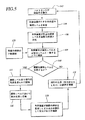
FPD10の好適な作動は、図5のフローチャートを参照することでよく理解できるはずである。
The preferred operation of
本発明は、周囲環境状態の関数として、蛍光光源16及び複数のLED46の組み合わせによって照光されるバックライト付きFPD10を提供し、FPD10の照度は、所望の最大昼光照度レベルと所望の最小夜間又は暗闇照度レベルとの間を滑らかに漸進的に変更することができる。蛍光光源16は、FPD10の所望の輝度レベルが所望の最大昼光照度レベル(以下、Lmaximumと呼ぶ)から低減レベルLtransitionまで及ぶ第1の輝度範囲(Rfluor)にある場合にFPD10を照光する。低減レベルは、LED46で得られる最大輝度より小さいが、依然として、蛍光光源16を蛍光灯プラズマの消失又は喪失を伴うことなく、即ち、連続的な一定輝度の照光出力を維持しながら、連続的な電流(即ち、100%デューティ比)によって作動させることができる最小照度レベルよりも大きい(ステップ106)。一方で、LED46は、低減レベルLtransitionから所望の最小夜間照度レベル(Lminimum)まで及ぶ第2の輝度範囲(RLED)の範囲でFPD10を照光するよう作動される。
The present invention provides a
制御装置40は、蛍光光源16及びLED46の出力を制御して、観察者に対して何ら違和感を与えることなく、LminimumからLtransitionを通ってLmaximumまでの及びその逆方向のFPD10の全作動範囲内において連続的かつ滑らかなFPD10の可変照度をもたらす。
The
一般に蛍光灯の出力照度レベルの意図された変更は、通常、蛍光灯に供給される電流を変化させることで実現できるであろう。同様に、LEDの出力照度レベルの意図された変更は、LEDに供給される電流又は電圧のいずれかを適切に変化させることで実現できる。しかし、蛍光灯及び/又はLEDに供給される電流又は電圧のいずれかの変更は、本発明の範疇にあり意図されたものであり、また、それぞれのデバイスの照光出力を選択的に変更するための任意の他の電気信号を用いることもできる。従って、本明細書で用いる場合、「電気制御信号」は、1つ又はそれ以上のこれらのデバイスの照度出力を選択的に変更するのに利用される電流又は電圧又は類似のものを意味することが意図されている。 In general, an intended change in the output intensity level of a fluorescent lamp will usually be achieved by changing the current supplied to the fluorescent lamp. Similarly, the intended change in the output illuminance level of the LED can be achieved by appropriately changing either the current or voltage supplied to the LED. However, any change in the current or voltage supplied to the fluorescent lamp and / or the LED is within the scope and intended of the present invention and to selectively change the illumination output of the respective device. Any other electrical signal can also be used. Thus, as used herein, “electrical control signal” means a current or voltage or the like used to selectively change the illumination output of one or more of these devices. Is intended.
この利点を機能的に達成するために、フォトセンサ36(及び/又はフォトセンサ38)は、ディスプレイ表面12上に入射する周辺光のレベル又は量を連続的に検出する(ステップ102)。FPD10上に入射する光レベルの検出に基づいて、制御装置40は、FPD10の所望の照度又は輝度レベルを求める(ステップ104)。フィードバック・フォトセンサ42は、検出したFPD10の現在の輝度レベルを制御装置40に供給し、制御装置40は、決定した所望の輝度レベルを実際に検出した輝度レベルと比較する(ステップ106)。
To functionally achieve this advantage, photosensor 36 (and / or photosensor 38) continuously detects the level or amount of ambient light incident on display surface 12 (step 102). Based on the detection of the light level incident on the
この比較に基づいて、制御装置40はFPD10の実際の輝度レベルを調節する。実際の輝度及び所望の輝度の両方が範囲Rfluor内にある場合、制御装置40は、その用途に望ましいパラメータ内で変更が行われるように、蛍光光源16へ流れる電流量を所定割合で単純に調節することができる。同様に、実際の輝度及び所望の輝度の両方が範囲RLED内にある場合、制御装置40は、LED46の出力がFPD10の所望の輝度レベルをもたらすように、LED46へ供給される電流量又は電圧量を単純に調節することができる(ステップ108)。制御装置40は、所望の輝度がLtransitionに達したか又は近づいたかを追加的に確認する必要がある(ステップ110)。そうでない場合(結果が「NO」)、Rfluor又はRLEDのいずれかの範囲内で調節を続ける。
Based on this comparison, the
実際の輝度と所望の輝度との間の差が、Ltransitionを交差するような調節の場合(ステップ110、結果が「YES」)、まず、制御装置40は、Ltransitionに達するまで蛍光光源16(照度レベルを低減すべき場合)又はLED46(照度レベルを高めるべき場合)のいずれかの出力レベルを調節することになる(ステップ114)。FPD10の実際の輝度がLtransitionに達すると、制御装置40は2つの照明光源を切り換える(ステップ16)。
If the adjustment is such that the difference between the actual brightness and the desired brightness crosses the L transition (
本発明のシステム及び方法の1つの重要な態様は、照度レベルが上限/明るい範囲Rfluorと下限/暗い範囲RLEDとの間を変化する際に、照度レベルLtransition又はその付近での作動方法である。本発明のこの態様により、特に、照明光源が蛍光光源16及びLED46の一方から他方に切り換えられる遷移レベルLtransition又はその付近において、FPD照度レベルをバックライティングの全範囲にわたって滑らかに連続的に変更することが可能になる。
One important aspect of the system and method of the present invention is the method of operating at or near the illumination level L transition as the illumination level changes between the upper / bright range R fluor and the lower / dark range R LED. It is. This aspect of the present invention smoothly and continuously changes the FPD illumination level over the entire range of backlighting, particularly at or near the transition level L transition where the illumination source is switched from one of the fluorescent
例えば、照明輝度をLmaximumからLminimumまで漸進的に低減又は暗くする際に、照度範囲Rfluor全体にわたり蛍光光源16に供給される電流は、蛍光光源16から発せられる照度がフォトセンサによってLtransitionになったと検出されるまで漸進的に低減される。この点まで、即ち、範囲Rfluor全体にわたって、LED46には作動出力が供給されない。例示的に、Ltransitionでの照度レベルは、蛍光光源16のプラズマを維持するには十分な約3ft−Lの輝度とすることができ、約5ft−LのLED46の最大輝度未満であることが適切である。蛍光光源16から発せられる光が低下してこの所定のLtransitionレベル達すると、蛍光光源16への供給電力は停止され、同時に、LEDへ電力が供給され、LEDは、電力が断たれた蛍光光源16からは供給されなくなった照明に置き換わるように即座に発光を開始する。
For example, when the illumination brightness is gradually reduced or darkened from L maximum to L minimum , the current supplied to the fluorescent
この作動全体にわたって、フィードバック・フォトセンサ42は、FPD10の照度を監視し、制御装置40によって、FPD10の照度が確実に所望のレベルとなるようにする。つまり、蛍光光源16がLtransition照度レベルでスイッチオフされると、LED46はスイッチオンされて代わりの照明光源となり、制御装置40及びフィードバック・フォトセンサ42は、LED46が適切な光量を発して蛍光光源16への電力を断った場合の喪失分を正確に元に戻すように、LED46への作動電力の供給を制御する。理論的に、このことは、電力が断たれた蛍光光源16からはもはや供給されないLtransitionの照度レベル、即ち正確な照度レベルをもたらすように、LEDに即座に電力を供給する必要があることを意味する。しかしながら、実際には、蛍光光源16の非活性化に伴って少量の残光が存在し、フィードバック・フォトセンサ42は絶えずFPD10に与えられる光量を監視しているのでこの残光を検出し(ステップ118)、制御装置40は、LEDの発光レベルを低減して、FPD照明の単数の又は複数の光源にかかわらず、FPD10の実際の全照度が依然として変わらないように、又は認知できないほどに滑らかな方法でもって少なくとも漸進的に変化し続けるように、蛍光光源16からの余分な残光を補償する。残光が弱まると、フィードバック・フォトセンサ42はFPD10の全照度の減少を検出してこの情報を制御装置40に入力し、制御装置40は、FPD10の照度が依然として変わらないようにLED46からの出力を高める。
Throughout this operation, the
従って、全体的な周辺光がLtransitionレベル以下に落ちると、LED46はFPD10を照光し(ここでは蛍光光源16は非活性又は不作動)、次に、制御装置40は、LED46への電流供給を滑らかに低減し続けることができ(ステップ112)、結果的にLminimumの最終的な目標輝度までFPD照度を漸進的に低減し続ける。
Thus, when the overall ambient light falls below the L transition level, the
前述とは逆のFPD照明輝度をLminimumからLtransitionを通ってLmaximumまで滑らかに高める場合の作動は、他の点では同じである。唯一の相違点は、この場合にはLED46が蛍光光源16の作動遅延を補償する必要がある点である。良く知られているように、蛍光灯は即座に点灯せず、蛍光灯内のプラズマが活性化するまで遅れがある。FPD10の輝度変化の滑らかな移り変わりを維持するために、LED46は、蛍光光源16が完全に活性化するまで蛍光灯の「欠落」量を補償する必要がある。従って、フィードバック・フォトセンサ42は、FPD10の実際の照度量を検出し、これを制御装置40に伝える必要がある。次に、制御装置40は、蛍光光源からの最大輝度の遅れを補償するためにFPD10に与える必要がある追加的な照明量を求め、LED46を十分に活性化して、RfluorとRLEDとの間の全体的に滑らかな移り変わりを維持するのに必要な追加的な照明量を発生させるようになっている。
The operation in the case where the FPD illumination luminance opposite to the above is smoothly increased from L minimum to L maximum through L transition is the same in other respects. The only difference is that in this case the
同様に理解されるように、本発明により、好都合には、任意の所望の割合で全範囲の任意の部分の全体にわたって、FPD照度レベルの滑らかで連続的な変更及び調節が可能になる。つまり、本発明は、Rfluor及びRLEDの組み合わせによって規定される範囲内の全体にわたって又はそれよりも狭い範囲にわたって、FPD照度を滑らかに変更するのに用いることが意図され考慮されている。従って、本発明のシステム及び方法は、滑らかな漸進的な方法及び適切な割合でもって、バックライト付きFPDの輝度レベルを動的に調節するのに使用でき、周辺光の状態において突然又は段階的を問わず、例えば、コックピットの全体ライティングの変化、又は航空機が密度の様々な雲層の中又は雲層の間を通過する際の外部輝度の変化、又は影、反射、ギラツキ、又はFPD10又はコックピット内の別の表面への直射日光の場合といった、任意の全ての変化に応答して、パイロット又は他の観察者には実質的に認知できない調節をもたらす。例えば、これらの周辺光等の変化は、フォトセンサ38等の1つ又は複数のフォトセンサで検出して、FPDの照明レベルに適した電流を決めるために適切な制御装置において使用できる。
As will also be appreciated, the present invention advantageously allows for a smooth and continuous change and adjustment of the FPD illumination level over any part of the full range at any desired rate. That is, the present invention is intended and contemplated to be used to smoothly change the FPD illuminance over the entire range defined by the combination of R fluor and R LED , or over a narrower range. Thus, the system and method of the present invention can be used to dynamically adjust the brightness level of a backlit FPD with a smooth gradual method and an appropriate ratio, suddenly or stepwise in ambient light conditions. Regardless of, for example, changes in the overall lighting of the cockpit, or changes in external brightness as the aircraft passes in or between cloud layers of varying density, or in shadows, reflections, glare, or
手動オフセット制御機器44を含む実施形態において、ユーザは、制御装置40による自動調節に優先して、FPD10の照度を個人の好みに合うように更に調節できる(ステップ120)。用途に応じては、調節のための単独の手段は手動式であってもよく、この場合、フォトセンサ36、38は不要になり、制御装置40は制御機器44から受信した信号の電線管になる。
In an embodiment that includes a manual offset
本発明のシステム及び方法は、フェイルセーフの非常用FPDバックアップライティング構成を好都合に提供し、これは蛍光光源16の故障時に、表示された画像又はデータを容易に見ることができるようにFPDのバックライティングを行うニーズが最も高い、少なくとも周囲光レベルが低い状態において作動的にLED46によってFPD10の照明を行うようになっていることを更に理解されたい。
The system and method of the present invention advantageously provides a fail-safe emergency FPD backup lighting configuration that allows the displayed image or data to be easily viewed upon failure of the fluorescent
本発明の別の実施形態において、前述の白色発光LEDの代わりに3色LEDを用いることができ、3色LEDは、赤色、緑色、及び青色(又は別の色又は設計的選択事項としての色の組み合わせ)の1つ又はそれ以上の色の光を作動的に発することができる。3色LEDを用いると、夜間等の周辺光レベルが低い状態において、本発明のシステム及び方法によってもたらされる照明の色を調整又は調節して、FPDに表示される画像又はデータをさらに見易くすることができ、更に、パイロットの例えば暗い航空機のコックピット又は操縦室内の別の計器及び器具及び作業を見る能力に対する障害(所謂、夜盲による)を未然に防ぐことができる。つまり、航空機コックピット内の所望の低いFPD照度レベルにおいて、3色LEDは、例示的に、LEDから発せられた光が可視光の色スペクトラムの赤色域まで着色されるように作動されることができる。別の変形された実施形態において、白色及び3色LEDを組み合わせて、照明の自由度を高め、白色光及び予め着色された光をLEDの別々の部分に使用することができるが、作動範囲RLEDは、やはり本発明の意図された範囲内及び考慮の範疇にある。 In another embodiment of the present invention, a three-color LED can be used in place of the aforementioned white light emitting LED, and the three-color LED can be red, green, and blue (or another color or color as a design choice) One or more colors of light) can be operatively emitted. Using a three-color LED to adjust or adjust the color of illumination provided by the system and method of the present invention at low ambient light levels, such as at night, to make the image or data displayed on the FPD more visible Furthermore, obstructions to the pilot's ability to see, for example, dark aircraft cockpits or other instruments and equipment in the cockpit and work (so-called night blindness) can be prevented. That is, at a desired low FPD illumination level in the aircraft cockpit, the three-color LED can illustratively be operated so that the light emitted from the LED is colored to the red region of the visible light color spectrum. . In another modified embodiment, white and tri-color LEDs can be combined to increase the degree of illumination and white light and pre-colored light can be used for separate parts of the LED, but the operating range R LEDs are still within the intended scope and consideration of the present invention.
本発明は航空機のコックピットに使用されるFPD10に関連して説明されているが、本発明のシステム及び方法は、別の分野において一般的な又は特定の有用性があるので、前述の説明は例示的なものであり、対象の使用分野を限定するものではないことを理解されたい。例えば、やはり限定するものではないが、本発明は、別の形式の乗り物、コンピュータ端末に使用されるFPD、機械装置や携帯型ゲームの操作に使用されるFPD、又は様々な周辺光状態の下でバックライト付きFPDを使用できる任意の別の環境で利用できる。
Although the present invention has been described in the context of an
本発明は、好適な実施形態に適合させて特定の新規な特徴が示されて説明され、更に指摘されているが、当業者であれば、本明細書で説明し示した方法及び装置において種々の省略、置換、及び変形を行い得ることを理解できるはずであり、これらの実施は、当業者であれば本発明の精神及び範疇から逸脱することなく行うことができるであろう。特に、同じ結果を得るために実質的に同じ方法でもって実質的に同じ機能を果たす、これらの構成要素及び方法ステップの全ての組み合わせは、本発明の範疇にあることが意図されている。また、説明された1つの実施形態から他のものへの方法ステップ及び構成要素の置換は完全に意図され考慮されている。従って、本発明は請求項によってのみ限定されることが意図されている。 While the invention has been illustrated and described, and further pointed out, specific novel features and adaptations to the preferred embodiments, those skilled in the art will recognize that various methods and apparatus described and shown herein may be used. It should be understood that omissions, substitutions, and modifications may be made and those implementations can be made by those skilled in the art without departing from the spirit and scope of the invention. In particular, all combinations of these components and method steps that perform substantially the same function in substantially the same way to obtain the same result are intended to be within the scope of the invention. Also, replacement of method steps and components from one described embodiment to another is fully contemplated and contemplated. Accordingly, it is intended that the invention be limited only by the claims.
Claims (4)
前記ディスプレイ画面上に入射する周辺光レベルを監視して、前記所定の最大及び最小照度レベルの間に定められた範囲内で所望のディスプレイ画面の照度レベルを決定する段階と、
前記ディスプレイ画面から発せられる光量である現在のディスプレイ画面の照度レベルを監視し、制御装置において、前記所望のディスプレイ画面の照度レベルを前記現在のディスプレイ画面の照度レベルと比較して、これら2つの照度レベルの差であるディスプレイ画面照度レベル差を求め、前記ディスプレイ画面照度レベル差に基づいて、ディスプレイ画面照度レベルを制御する段階と、
を含み、前記ディスプレイ画面照度レベルの制御は、
前記決定された所望のディスプレイ画面照度レベルが、前記所定の最大照度レベルと、該所定の最大照度レベルよりは小さいが前記所定の最小照度レベルよりは大きい所定の遷移照度レベルとの間にある場合に、前記決定された所望のディスプレイ画面照度レベルで前記ディスプレイ画面を照光できるように、前記ディスプレイ画面を照光するために配置されている蛍光灯を作動させるための100%デューティ比蛍光灯電気制御信号を、前記ディスプレイ画面を前記所定の最大照度レベルで照光するための第1の蛍光灯制御信号レベルと、前記ディスプレイ画面を前記所定の遷移照度レベルで照光するための、前記所定の最大照度レベルよりも小さいが前記所定の最小照度レベルよりも大きく、更に100%デューティ比での蛍光灯からの連続的な一定輝度出力を維持することができる蛍光灯の最小作動制御信号レベルよりも大きい第2の蛍光灯制御信号レベルとの間で変更し、
前記決定された所望のディスプレイ画面照度レベルが前記所定の遷移照度レベルと前記所定の最小照度レベルとの間にある場合に、前記決定された所望のディスプレイ画面照度レベルで前記ディスプレイ画面を照光できるように、前記ディスプレイ画面を照光するために配置されている少なくとも1つの発光ダイオードを作動させるためのLED電気制御信号を、前記ディスプレイ画面を前記所定の遷移照度レベルで照光するための第1のLED制御信号レベルと、前記ディスプレイ画面を前記所定の最小照度レベルで照光するための第2のLED制御信号レベルとの間で変更し、
前記所望のディスプレイ画面照度レベルが前記所定の遷移照度レベルまで低下したときに、前記蛍光灯への前記蛍光灯制御信号の供給を中断して前記蛍光灯からの照明出力を中断し、前記少なくとも1つの発光ダイオードにLED制御信号を供給し、前記監視された現在のディスプレイ画面照度レベルに応じて前記LED制御信号を変更して、前記決定された所望のディスプレイ画面照度レベルで前記ディスプレイ画面を照光し、
前記所望のディスプレイ画面照度レベルが前記所定の遷移照度レベルまで上昇したときに、前記蛍光灯への前記蛍光灯制御信号の供給を開始して前記蛍光灯からの照明出力を開始し、前記監視された現在のディスプレイ画面照度レベルに応じて前記LED制御信号を変更して、前記蛍光灯への電力供給の初期に前記蛍光灯が前記ディスプレイ画面を前記決定された所望のディスプレイ画面照度レベルにて照光するのを加勢し、前記ディスプレイ画面照度レベル差が、前記蛍光灯の前記照明出力によって前記決定された所望のディスプレイ画面照度レベルに前記ディスプレイ画面を照光できる状態であることを示す場合に、前記少なくとも1つの発光ダイオードへの前記LED制御信号の供給を中断する、
ことによって行われ、前記決定された所望のディスプレイ画面照度レベルで前記ディスプレイ画面を照光することを特徴とする方法。Illumination level of the display screen between a predetermined maximum illumination level used to view the display screen in ambient daylight conditions and a predetermined minimum illumination level used to view the display screen in ambient night conditions In a method of illuminating a display screen of a flat panel display device so as to smoothly and dynamically change,
Monitoring the ambient light level incident on the display screen to determine a desired display screen illumination level within a range defined between the predetermined maximum and minimum illumination levels;
The illuminance level of the current display screen, which is the amount of light emitted from the display screen, is monitored, and the control device compares the illuminance level of the desired display screen with the illuminance level of the current display screen. Obtaining a display screen illuminance level difference which is a level difference, and controlling the display screen illuminance level based on the display screen illuminance level difference ; and
The display screen illuminance level is controlled by :
The determined desired display screen illuminance level is between the predetermined maximum illuminance level and a predetermined transition illuminance level that is smaller than the predetermined maximum illuminance level but greater than the predetermined minimum illuminance level. And a 100% duty ratio fluorescent lamp electrical control signal for operating a fluorescent lamp arranged to illuminate the display screen so that the display screen can be illuminated at the determined desired display screen illuminance level. A first fluorescent lamp control signal level for illuminating the display screen at the predetermined maximum illuminance level, and a predetermined maximum illuminance level for illuminating the display screen at the predetermined transition illuminance level. Is smaller than the predetermined minimum illuminance level, and further from the fluorescent lamp at 100% duty ratio. Change between-sustaining constant luminance output second greater than the fluorescent lamp minimum operating control signal level that can maintain the fluorescent lamp control signal level,
When the determined desired display screen illuminance level is between the predetermined transition illuminance level and the predetermined minimum illuminance level, the display screen can be illuminated with the determined desired display screen illuminance level. A first LED control for illuminating the display screen at the predetermined transition illuminance level with an LED electrical control signal for activating at least one light emitting diode arranged to illuminate the display screen. Changing between a signal level and a second LED control signal level for illuminating the display screen at the predetermined minimum illumination level;
When the desired display screen illuminance level decreases to the predetermined transition illuminance level, the supply of the fluorescent lamp control signal to the fluorescent lamp is interrupted to interrupt the illumination output from the fluorescent lamp, and the at least one Supply LED control signals to two light emitting diodes, change the LED control signals according to the monitored current display screen illuminance level, and illuminate the display screen at the determined desired display screen illuminance level ,
When the desired display screen illuminance level rises to the predetermined transition illuminance level, supply of the fluorescent lamp control signal to the fluorescent lamp is started to start illumination output from the fluorescent lamp, and the monitored The LED control signal is changed according to the current display screen illuminance level, and the fluorescent lamp illuminates the display screen at the determined desired display screen illuminance level at the initial stage of power supply to the fluorescent lamp. The display screen illuminance level difference indicates that the display screen can be illuminated to the desired display screen illuminance level determined by the illumination output of the fluorescent lamp. Interrupting the supply of the LED control signal to one light emitting diode;
Method characterized by illuminating said display screen performed, the determined desired display screen illumination level by.
前記ディスプレイ画面上に入射する周辺光レベルを監視して、前記所定の最大及び最小照度レベルの間に定められた範囲内で所望のディスプレイ画面の照度レベルを決定するための周辺光センサと、
前記ディスプレイ画面から発せられる光量である現在のディスプレイ画面の照度レベルを監視するためのディスプレイ照度レベルセンサと、
前記ディスプレイ画面を照光するために配置されている蛍光灯と、
前記ディスプレイ画面を照光するために配置されている少なくとも1つの発光ダイオードと、
前記周辺光センサに接続されて、監視により得られた入射周辺光レベルから、前記所定の最大及び最小照度レベルの間に定められた範囲内の所望のディスプレイ画面照度レベルを決定し、前記ディスプレイ照度レベルセンサに接続されて、監視により得られた現在のディスプレイ画面照度レベルを受信し、更に前記蛍光灯及び前記少なくとも1つの発光ダイオードに接続され、前記所望のディスプレイ画面の照度レベルを前記現在のディスプレイ画面の照度レベルと比較して、これら2つの照度レベルの差であるディスプレイ画面照度レベル差を求め、前記ディスプレイ画面照度レベル差に基づいて、ディスプレイ画面照度レベルを制御するディスプレイ画面照度レベル制御装置と、
を備え、前記ディスプレイ画面照度レベル制御装置は、
前記決定された所望のディスプレイ画面照度レベルが前記所定の最大照度レベルと、該所定の最大照度レベルよりは小さいが前記所定の最小照度レベルよりは大きい所定の遷移照度レベルとの間にある場合に、前記決定された所望のディスプレイ画面照度レベルで前記ディスプレイ画面を照光できるように、前記蛍光灯を作動させるための100%デューティ比蛍光灯電気制御信号を、前記ディスプレイ画面を前記所定の最大照度レベルで照光するための第1の蛍光灯制御信号レベルと、前記ディスプレイ画面を所定の遷移照度レベルで照光するための、前記所定の最大照度レベルよりも小さいが前記所定の最小照度レベルよりも大きく、更に100%デューティ比での蛍光灯からの連続的な一定輝度出力を維持することができる蛍光灯の最小作動制御信号レベルよりも大きい第2の蛍光灯制御信号レベルとの間で変更し、
前記決定された所望のディスプレイ画面照度レベルが前記所定の遷移照度レベルと前記所定の最小照度レベルとの間にある場合に、前記決定された所望のディスプレイ画面照度レベルにおいて前記ディスプレイ画面を照光できるように、前記少なくとも1つの発光ダイオードを作動させるためのLED電気制御信号を、前記ディスプレイ画面を前記所定の遷移照度レベルで照光するための第1のLED制御信号レベルと、前記ディスプレイ画面を前記所定の最小照度レベルで照光するための第2のLED制御信号レベルとの間で変更し、
前記所望のディスプレイ画面照度レベルが前記所定の遷移照度レベルまで低下したときに、前記蛍光灯への前記蛍光灯制御信号の供給を中断して前記蛍光灯からの照明出力を中断し、前記少なくとも1つの発光ダイオードにLED制御信号を供給し、前記監視により得られた現在のディスプレイ画面照度レベルに応じて前記LED制御信号を変更して、前記決定された所望のディスプレイ画面照度レベルで前記ディスプレイ画面を照光し、
前記所望のディスプレイ画面の照度レベルが前記所定の遷移照度レベルまで上昇したときに、前記蛍光灯への前記蛍光灯制御信号の供給を開始して前記蛍光灯からの照明出力を開始させ、前記監視された現在のディスプレイ画面照度レベルに応じて前記LED制御信号を変更して、前記蛍光灯への電力供給の初期に前記蛍光灯が前記ディスプレイ画面を前記決定された所望のディスプレイ画面の照度レベルにて照光するのを加勢し、前記ディスプレイ画面照度レベル差が、前記蛍光灯の前記照明出力によって前記決定された所望のディスプレイ画面照度レベルに前記ディスプレイ画面を照光できる状態であることを示す場合に、前記少なくとも1つの発光ダイオードへの前記LED制御信号の供給を中断する、
ことによって前記決定された所望のディスプレイ画面照度レベルで前記ディスプレイ画面を照光するように作動することを特徴とする装置。Illumination level of the display screen between a predetermined maximum illumination level used to view the display screen in ambient daylight conditions and a predetermined minimum illumination level used to view the display screen in ambient night conditions In a device that illuminates the display screen of a flat panel display device so as to change smoothly and dynamically,
An ambient light sensor for monitoring the ambient light level incident on the display screen and determining a desired display screen illumination level within a range defined between the predetermined maximum and minimum illumination levels;
A display illuminance level sensor for monitoring the illuminance level of the current display screen, which is the amount of light emitted from the display screen ;
A fluorescent lamp arranged to illuminate the display screen;
At least one light emitting diode arranged to illuminate the display screen;
Is connected to the ambient light sensor from the resulting incoming ambient light levels by the monitoring, determines the desired display screen illumination level within a range defined between the predetermined maximum and minimum illumination levels, the display illumination is connected to the level sensor, receives the current display screen illumination level obtained by the monitoring, further the fluorescent lamp and connected to said at least one light emitting diode, the illumination level of the desired display screen of the currently displayed A display screen illuminance level control device for obtaining a display screen illuminance level difference, which is a difference between these two illuminance levels, in comparison with the illuminance level of the screen, and controlling the display screen illuminance level based on the display screen illuminance level difference; ,
The display screen illuminance level control device comprises:
The determined desired display screen illuminance level is between the predetermined maximum illuminance level and a predetermined transition illuminance level that is less than the predetermined maximum illuminance level but greater than the predetermined minimum illuminance level; A 100% duty ratio fluorescent lamp electrical control signal for operating the fluorescent lamp so that the display screen can be illuminated at the determined desired display screen illuminance level, and the display screen at the predetermined maximum illuminance level. A first fluorescent lamp control signal level for illuminating with, and for illuminating the display screen with a predetermined transition illuminance level smaller than the predetermined maximum illuminance level but greater than the predetermined minimum illuminance level, In addition, fluorescent lamps that can maintain a continuous constant luminance output from a fluorescent lamp at a 100% duty ratio. Change between the actuation control signal the second greater than the level fluorescent lamp control signal level,
When the determined desired display screen illuminance level is between the predetermined transition illuminance level and the predetermined minimum illuminance level, the display screen can be illuminated at the determined desired display screen illuminance level. An LED electrical control signal for activating the at least one light emitting diode, a first LED control signal level for illuminating the display screen at the predetermined transition illuminance level, and the display screen at the predetermined level. Change between the second LED control signal level to illuminate at the minimum illumination level,
When the desired display screen illuminance level decreases to the predetermined transition illuminance level, the supply of the fluorescent lamp control signal to the fluorescent lamp is interrupted to interrupt the illumination output from the fluorescent lamp, and the at least one LED control signals are supplied to two light emitting diodes, the LED control signals are changed according to the current display screen illuminance level obtained by the monitoring, and the display screen is changed to the determined desired display screen illuminance level. Illuminated,
When the illuminance level of the desired display screen rises to the predetermined transition illuminance level, supply of the fluorescent lamp control signal to the fluorescent lamp is started to start illumination output from the fluorescent lamp, and the monitoring The LED control signal is changed according to the current display screen illuminance level, and the fluorescent lamp changes the display screen to the determined desired illuminance level of the display screen at the initial stage of power supply to the fluorescent lamp. The display screen illuminance level difference indicates that the display screen can be illuminated to the desired display screen illuminance level determined by the illumination output of the fluorescent lamp, Interrupting the supply of the LED control signal to the at least one light emitting diode;
And wherein that you operate to illuminate the display screen at the desired display screen illumination level is the determined by.
前記ディスプレイ画面から発せられる光量である現在の前記ディスプレイ画面照度レベルを監視するためのディスプレイ照度レベルセンサと、
前記所定の最大輝度レベルと前記所定の最大照度レベルよりも小さいが前記所定の最小照度レベルよりも大きい所定の遷移輝度レベルとの間に定められた、第1のディスプレイ画面照光範囲内に含まれるディスプレイ画面照光レベルで、前記ディスプレイ画面を照光するために配置されている蛍光灯と、
前記所定の遷移輝度レベルと前記所定の最小輝度レベルとの間に定められた、第2のディスプレイ画面照光範囲内に含まれるディスプレイ画面照光レベルで、前記ディスプレイ画面を照光するために配置されている発光ダイオードと、
前記ディスプレイ照度レベルセンサ、前記蛍光灯、及び前記発光ダイオードに接続されているディスプレイ画面照度レベル制御装置と、
を備え、前記ディスプレイ画面照度レベル制御装置は、
前記第1のディスプレイ画面照度範囲内のディスプレイ画面照度レベルで、前記作動蛍光灯を用いて前記ディスプレイ画面を照光するために、前記蛍光灯を作動させるための蛍光灯電気制御信号を、前記ディスプレイ画面を前記所定の最大照度レベルで照光するための第1の蛍光灯制御信号レベルと前記ディスプレイ画面を前記所定の遷移照度レベルで照光するための第2の蛍光灯制御信号レベルとの間で変更し、
前記現在の所望のディスプレイ画面照度レベルが前記第1のディスプレイ画面照度範囲から前記第2のディスプレイ画面照度範囲へ変更される場合に、前記第2のディスプレイ画面照度範囲において前記蛍光灯を遮断するために、前記蛍光灯への前記蛍光灯電気制御信号を中断し、
前記現在の所望のディスプレイ画面の照度レベルが前記第2のディスプレイ画面照度範囲から前記第1のディスプレイ画面照度範囲へ変更される場合に、前記第1のディスプレイ画面照度範囲において前記ディスプレイ画面を予め定められた照度レベルに照射するように前記蛍光灯を作動させるために、前記蛍光灯への前記蛍光灯電気制御信号の供給を開始し、
前記第2のディスプレイ画面照度範囲内のディスプレイ画面照光レベルで、前記発光ダイオードを用いて前記ディスプレイ画面を照光するために、前記発光ダイオードを作動させるためのLED制御信号を、前記ディスプレイ画面を前記所定の遷移照度レベルで照光するための第1のLED制御信号レベルと前記ディスプレイ画面を前記所定の最小照度レベルで照光するための第2のLED制御信号レベルとの間で変更し、
(i)前記現在の所望のディスプレイ画面照度レベルが前記第1のディスプレイ画面照度範囲から前記第2のディスプレイ画面照度範囲へ変更される場合に、蛍光灯の遮断時の蛍光灯残光を補正するために、前記監視された現在のディスプレイ画面照光レベル及び前記現在の所望のディスプレイ画面照光レベルに応じて前記LED電気信号を低減すること、又は
(ii)前記現在の所望のディスプレイ画面の照度レベルが前記第2のディスプレイ画面照度範囲から前記第1のディスプレイ画面照度範囲へ変更される場合に、前記蛍光灯の起動初期の蛍光灯起動遅れ及び蛍光灯起動照明レベル変動を補正するために、前記監視された現在のディスプレイ画面照光レベル及び前記現在の所望のディスプレイ画面照光レベルに応じて前記LED電気信号を高めること、
によって、前記LED制御信号を変更し、結果的に、前記ディスプレイ画面照光レベルが前記最大ディスプレイ画面照光レベルと前記最大ディスプレイ画面照光レベルとの間を動的に変更される場合に、前記ディスプレイ画面照光レベルの連続した滑らかな変化を維持する、
ように前記蛍光灯及び前記少なくとも1つの発光ダイオードの作動を制御して、前記ディスプレイ画面を現在の所望のディスプレイ画面照光レベルで照光できるように、滑らかに動的に前記ディスプレイ画面の照度を前記所定の最大及び最小照度レベルの間で選択的に変更するように作動することを特徴とする装置。Illumination level of the display screen between a predetermined maximum illumination level used to view the display screen in ambient daylight conditions and a predetermined minimum illumination level used to view the display screen in ambient night conditions In a device that illuminates the display screen of a flat panel display device so as to change smoothly and dynamically,
A display illuminance level sensor for monitoring the current display screen illuminance level which is the amount of light emitted from the display screen ;
Included within a first display screen illumination range defined between the predetermined maximum luminance level and a predetermined transition luminance level that is less than the predetermined maximum illuminance level but greater than the predetermined minimum illuminance level. A fluorescent lamp arranged to illuminate the display screen at a display screen illumination level;
Arranged to illuminate the display screen at a display screen illumination level defined within the second display screen illumination range, defined between the predetermined transition luminance level and the predetermined minimum luminance level. A light emitting diode;
A display screen illuminance level control device connected to the display illuminance level sensor, the fluorescent lamp, and the light emitting diode;
The display screen illuminance level control device comprises:
A fluorescent lamp electrical control signal for operating the fluorescent lamp to illuminate the display screen with the operating fluorescent lamp at a display screen illuminance level within the first display screen illuminance range; Between a first fluorescent lamp control signal level for illuminating at the predetermined maximum illuminance level and a second fluorescent lamp control signal level for illuminating the display screen at the predetermined transition illuminance level. ,
To block the fluorescent light in the second display screen illuminance range when the current desired display screen illuminance level is changed from the first display screen illuminance range to the second display screen illuminance range To interrupt the fluorescent lamp electrical control signal to the fluorescent lamp,
When the current desired display screen illumination level is changed from the second display screen illumination range to the first display screen illumination range, the display screen is predetermined in the first display screen illumination range. In order to operate the fluorescent lamp so as to irradiate a given illuminance level, start supplying the fluorescent lamp electrical control signal to the fluorescent lamp;
In order to illuminate the display screen using the light emitting diode at a display screen illumination level within the second display screen illuminance range, an LED control signal for operating the light emitting diode is transmitted to the predetermined display screen. Changing between a first LED control signal level for illuminating at a transition illuminance level and a second LED control signal level for illuminating the display screen at the predetermined minimum illuminance level;
(I) When the current desired display screen illuminance level is changed from the first display screen illuminance range to the second display screen illuminance range, the afterglow of the fluorescent lamp when the fluorescent lamp is shut off is corrected. In order to reduce the LED electrical signal in response to the monitored current display screen illumination level and the current desired display screen illumination level, or (ii) the current desired display screen illumination level is When the second display screen illuminance range is changed from the second display screen illuminance range to the first display screen illuminance range, the monitoring is performed in order to correct the fluorescent lamp activation delay and the fluorescent lamp activation illumination level fluctuation at the initial activation of the fluorescent lamp. Depending on the current display screen illumination level and the current desired display screen illumination level. To raise the issue,
To change the LED control signal, and as a result, the display screen illumination level when the display screen illumination level is dynamically changed between the maximum display screen illumination level and the maximum display screen illumination level. Maintain a continuous and smooth change in level,
Controlling the operation of the fluorescent lamp and the at least one light emitting diode to smoothly illuminate the display screen dynamically so that the display screen can be illuminated at a current desired display screen illumination level. actuating be and wherein the Rukoto to selectively changed between the maximum and minimum illumination levels.
前記ディスプレイ画面から発せられる光量である現在の前記ディスプレイ画面照度レベルを監視する段階と、
前記所定の最大輝度レベルと前記所定の最大照度レベルよりも小さいが前記所定の最小照度レベルよりも大きい所定の遷移輝度レベルとの間に定められた、第1のディスプレイ画面照光範囲内に含まれるディスプレイ画面照光レベルで、前記ディスプレイ画面を照光するために蛍光灯を配置する段階と、
前記所定の遷移輝度レベルと前記所定の最小輝度レベルとの間に定められた、第2のディスプレイ画面照光範囲内に含まれるディスプレイ画面照光レベルで、前記ディスプレイ画面を照光するために発光ダイオードを配置する段階と、
前記蛍光灯及び前記発光ダイオードを制御する段階と、
を含み、前記制御段階は、
前記第1のディスプレイ画面照度範囲内のディスプレイ画面照度レベルで、前記蛍光灯を用いて前記ディスプレイ画面を照光するために、前記蛍光灯を作動させるための蛍光灯電気制御信号を、前記ディスプレイ画面を前記所定の最大照度レベルで照光するための第1の蛍光灯制御信号レベルと前記ディスプレイ画面を前記所定の遷移照度レベルで照光するための第2の蛍光灯制御信号レベルとの間で変更し、
前記現在の所望のディスプレイ画面照度レベルが前記第1のディスプレイ画面照度範囲から前記第2のディスプレイ画面照度範囲へ変更される場合に、前記第2のディスプレイ画面照度範囲において前記蛍光灯を遮断するために、前記蛍光灯への前記蛍光灯電気制御信号を中断し、
前記現在の所望のディスプレイ画面の照度レベルが前記第2のディスプレイ画面照度範囲から前記第1のディスプレイ画面照度範囲へ変更される場合に、前記第1のディスプレイ画面照度範囲において前記ディスプレイ画面を予め定められた照度レベルに照射するように前記蛍光灯に電源を供給するために、前記蛍光灯への前記蛍光灯電気制御信号を開始し、
前記第2のディスプレイ画面照度範囲内のディスプレイ画面照光レベルで、前記発光ダイオードを用いて前記ディスプレイ画面を照光するために、前記発光ダイオードを作動させるためのLED制御信号を、前記ディスプレイ画面を前記所定の遷移照度レベルで照光するための第1のLED制御信号レベルと前記ディスプレイ画面を前記所定の最小照度レベルで照光するための第2のLED制御信号レベルとの間で変更し、
(i)前記現在の所望のディスプレイ画面照度レベルが前記第1のディスプレイ画面照度範囲から前記第2のディスプレイ画面照度範囲へ変更される場合に、蛍光灯の遮断時の蛍光灯残光を補正するために、前記監視された現在のディスプレイ画面照光レベル及び前記現在の所望のディスプレイ画面照光レベルに応じて前記LED電気信号を低減すること、又は
(ii)前記現在の所望のディスプレイ画面の照度レベルが前記第2のディスプレイ画面照度範囲から前記第1のディスプレイ画面照度範囲へ変更される場合に、前記蛍光灯の起動初期の蛍光灯起動遅れ及び蛍光灯起動照明レベル変動を補正するために、前記監視された現在のディスプレイ画面照光レベル及び前記現在の所望のディスプレイ画面照光レベルに応じて前記LED電気信号を高めること、
によって、前記LED制御信号を変更し、結果的に、前記ディスプレイ画面照光レベルが前記最大ディスプレイ画面照光レベルと前記最大ディスプレイ画面照光レベルとの間を動的に変更される場合に、前記ディスプレイ画面照光レベルの連続した滑らかな変化を維持する、
ことによって、前記ディスプレイ画面を現在の所望のディスプレイ画面照光レベルで照光できるように、滑らかに動的に前記ディスプレイ画面の照度を前記所定の最大及び最小照度レベルの間で選択的に変更する
ことを特徴とする方法。Illumination level of the display screen between a predetermined maximum illumination level used to view the display screen in ambient daylight conditions and a predetermined minimum illumination level used to view the display screen in ambient night conditions In a method of illuminating a display screen of a flat panel display device so as to smoothly and dynamically change,
Monitoring the current display screen illuminance level, which is the amount of light emitted from the display screen ;
Included within a first display screen illumination range defined between the predetermined maximum luminance level and a predetermined transition luminance level that is less than the predetermined maximum illuminance level but greater than the predetermined minimum illuminance level. Placing a fluorescent lamp to illuminate the display screen at a display screen illumination level;
A light emitting diode is arranged to illuminate the display screen at a display screen illumination level that is defined between the predetermined transition luminance level and the predetermined minimum luminance level and is included in a second display screen illumination range. And the stage of
Controlling the fluorescent lamp and the light emitting diode;
The control step includes:
In order to illuminate the display screen with the fluorescent lamp at a display screen illuminance level within the first display screen illuminance range, a fluorescent lamp electrical control signal for operating the fluorescent lamp is transmitted to the display screen. Changing between a first fluorescent light control signal level for illuminating at the predetermined maximum illuminance level and a second fluorescent light control signal level for illuminating the display screen at the predetermined transition illuminance level;
To block the fluorescent light in the second display screen illuminance range when the current desired display screen illuminance level is changed from the first display screen illuminance range to the second display screen illuminance range To interrupt the fluorescent lamp electrical control signal to the fluorescent lamp,
When the current desired display screen illumination level is changed from the second display screen illumination range to the first display screen illumination range, the display screen is predetermined in the first display screen illumination range. Initiating the fluorescent light electrical control signal to the fluorescent light to supply power to the fluorescent light to illuminate a given illuminance level;
In order to illuminate the display screen using the light emitting diode at a display screen illumination level within the second display screen illuminance range, an LED control signal for operating the light emitting diode is transmitted to the predetermined display screen. Changing between a first LED control signal level for illuminating at a transition illuminance level and a second LED control signal level for illuminating the display screen at the predetermined minimum illuminance level;
(I) When the current desired display screen illuminance level is changed from the first display screen illuminance range to the second display screen illuminance range, the afterglow of the fluorescent lamp when the fluorescent lamp is shut off is corrected. In order to reduce the LED electrical signal in response to the monitored current display screen illumination level and the current desired display screen illumination level, or (ii) the current desired display screen illumination level is When the second display screen illuminance range is changed from the second display screen illuminance range to the first display screen illuminance range, the monitoring is performed in order to correct the fluorescent lamp activation delay and the fluorescent lamp activation illumination level fluctuation at the initial activation of the fluorescent lamp. Depending on the current display screen illumination level and the current desired display screen illumination level. To raise the issue,
To change the LED control signal, and as a result, the display screen illumination level when the display screen illumination level is dynamically changed between the maximum display screen illumination level and the maximum display screen illumination level. Maintain a continuous and smooth change in level,
To selectively change the illuminance of the display screen between the predetermined maximum and minimum illuminance levels smoothly and dynamically so that the display screen can be illuminated at a current desired display screen illumination level. Feature method.
Applications Claiming Priority (3)
| Application Number | Priority Date | Filing Date | Title |
|---|---|---|---|
| US39350202P | 2002-07-03 | 2002-07-03 | |
| US60/393,502 | 2002-07-03 | ||
| PCT/US2003/021141 WO2004006220A1 (en) | 2002-07-03 | 2003-07-03 | Method and apparatus for illuminating a flat panel display with a variably-adjustable backlight |
Publications (2)
| Publication Number | Publication Date |
|---|---|
| JP2005532593A JP2005532593A (en) | 2005-10-27 |
| JP5085846B2 true JP5085846B2 (en) | 2012-11-28 |
Family
ID=30115593
Family Applications (1)
| Application Number | Title | Priority Date | Filing Date |
|---|---|---|---|
| JP2004519927A Expired - Lifetime JP5085846B2 (en) | 2002-07-03 | 2003-07-03 | Method and apparatus for illuminating a flat panel display device using an adjustable backlight |
Country Status (6)
| Country | Link |
|---|---|
| US (1) | US7656383B2 (en) |
| EP (1) | EP1527436B1 (en) |
| JP (1) | JP5085846B2 (en) |
| KR (1) | KR100845148B1 (en) |
| AU (1) | AU2003256395A1 (en) |
| WO (1) | WO2004006220A1 (en) |
Families Citing this family (35)
| Publication number | Priority date | Publication date | Assignee | Title |
|---|---|---|---|---|
| FR2854252B1 (en) * | 2003-04-25 | 2005-08-05 | Thales Sa | COLORIMETRIC PHOTO PARAMETERS ASSEMBLY DEVICE FOR COLOR LED LUMINATED BOX |
| JP3661692B2 (en) * | 2003-05-30 | 2005-06-15 | セイコーエプソン株式会社 | Illumination device, projection display device, and driving method thereof |
| US7336255B2 (en) * | 2003-12-31 | 2008-02-26 | Intel Corporation | Selectable continuous and burst mode backlight voltage inverter |
| EP1605433A1 (en) | 2004-06-02 | 2005-12-14 | Research In Motion Limited | Backlight control for a handheld computing device |
| KR101090751B1 (en) * | 2004-06-29 | 2011-12-08 | 엘지디스플레이 주식회사 | LCD with a back-light assembly |
| KR100640063B1 (en) * | 2005-02-18 | 2006-10-31 | 삼성전자주식회사 | Method for enhancing image considering to exterior illuminance and apparatus thereof |
| US7515822B2 (en) * | 2006-05-12 | 2009-04-07 | Microsoft Corporation | Imaging systems' direct illumination level adjusting method and system involves adjusting operation of image sensor of imaging system based on detected level of ambient illumination |
| KR101284926B1 (en) * | 2006-06-23 | 2013-07-10 | 엘지디스플레이 주식회사 | Liquid Crystal Display Device And fabricating Method and Driving Method Thereof |
| KR100836433B1 (en) * | 2007-02-05 | 2008-06-09 | 삼성에스디아이 주식회사 | Organic light emitting display device and driving method thereof |
| KR100836438B1 (en) * | 2007-02-05 | 2008-06-09 | 삼성에스디아이 주식회사 | Organic light emitting display device and driving method thereof |
| KR100836424B1 (en) * | 2007-02-05 | 2008-06-09 | 삼성에스디아이 주식회사 | Organic light emitting display device and driving method thereof |
| KR100836425B1 (en) * | 2007-02-05 | 2008-06-09 | 삼성에스디아이 주식회사 | Organic light emitting display device and driving method thereof |
| KR100836423B1 (en) * | 2007-02-05 | 2008-06-09 | 삼성에스디아이 주식회사 | Organic light emitting display device and driving method thereof |
| KR100836432B1 (en) * | 2007-02-05 | 2008-06-09 | 삼성에스디아이 주식회사 | Organic light emitting display device and driving method thereof |
| KR100855472B1 (en) | 2007-02-07 | 2008-09-01 | 삼성전자주식회사 | Apparatus and method for driving low-power |
| JP4952286B2 (en) * | 2007-02-15 | 2012-06-13 | 船井電機株式会社 | Information display device |
| KR100840102B1 (en) * | 2007-02-23 | 2008-06-19 | 삼성에스디아이 주식회사 | Organic light emitting display and drinvig method thereof |
| KR101331903B1 (en) | 2007-03-22 | 2013-11-22 | 엘지디스플레이 주식회사 | Liquid crystal display device |
| US20080247128A1 (en) * | 2007-04-03 | 2008-10-09 | Soon Huat Khoo | Composite Two Screen Digital Device |
| KR101480357B1 (en) * | 2007-11-23 | 2015-01-12 | 삼성디스플레이 주식회사 | Back light unit and liquid crystal display having the same |
| JP2009229540A (en) * | 2008-03-19 | 2009-10-08 | Toshiba Corp | Driving device and driving method of liquid crystal device |
| JP4586883B2 (en) * | 2008-05-23 | 2010-11-24 | ソニー株式会社 | Liquid crystal display device and driving method thereof |
| KR101461022B1 (en) * | 2008-05-30 | 2014-11-14 | 엘지디스플레이 주식회사 | Display device, and method of driving the same |
| JP2010122251A (en) * | 2008-11-17 | 2010-06-03 | Toshiba Corp | Image display device and method |
| KR101606868B1 (en) * | 2010-02-01 | 2016-03-28 | 한온시스템 주식회사 | Air conditioning system for automotive vehicles |
| US9119261B2 (en) | 2010-07-26 | 2015-08-25 | Apple Inc. | Display brightness control temporal response |
| EP2413310B1 (en) * | 2010-07-26 | 2017-08-23 | Apple Inc. | Display Brightness Control Temporal Response |
| US20120182276A1 (en) * | 2011-01-19 | 2012-07-19 | Broadcom Corporation | Automatic adjustment of display systems based on light at viewer position |
| FR2976150B1 (en) * | 2011-06-01 | 2013-06-14 | Thales Sa | DEVICE FOR CONTROLLING VERY LUMINOUS DYNAMIC LIGHT-EMITTING DIODES FOR DISPLAY SCREEN |
| WO2013179370A1 (en) * | 2012-05-28 | 2013-12-05 | Necディスプレイソリューションズ株式会社 | Led backlight display device and led backlight arrangement method |
| US9471158B2 (en) * | 2013-06-05 | 2016-10-18 | Ricky Latella | Universal stylus |
| WO2017007220A1 (en) * | 2015-07-06 | 2017-01-12 | 삼성전자 주식회사 | Electronic device and display control method in electronic device |
| CN105575366B (en) * | 2016-02-26 | 2017-10-24 | 广东欧珀移动通信有限公司 | Switch the method and system of backlight governing speed |
| KR102277885B1 (en) * | 2020-02-21 | 2021-07-14 | 가톨릭대학교 산학협력단 | Health lighting apparatus and control method thereof |
| US20230106412A1 (en) * | 2020-05-29 | 2023-04-06 | Stryker Corporation | Patient support apparatus with automatic display control |
Family Cites Families (14)
| Publication number | Priority date | Publication date | Assignee | Title |
|---|---|---|---|---|
| US470389A (en) * | 1892-03-08 | Territory | ||
| JPS62125329A (en) * | 1985-11-27 | 1987-06-06 | Hosiden Electronics Co Ltd | Transmission type display device |
| FR2637717B1 (en) * | 1988-10-11 | 1990-11-16 | Thomson Csf | LIGHT BOX FOR AVIONIC VISUALIZATION DEVICE |
| JPH03296018A (en) * | 1990-04-16 | 1991-12-26 | Matsushita Electric Ind Co Ltd | Liquid crystal display device |
| US5143433A (en) | 1991-11-01 | 1992-09-01 | Litton Systems Canada Limited | Night vision backlighting system for liquid crystal displays |
| US5760760A (en) * | 1995-07-17 | 1998-06-02 | Dell Usa, L.P. | Intelligent LCD brightness control system |
| US6028597A (en) | 1996-01-25 | 2000-02-22 | American Signal Company | Power manager system for highway signage |
| US5886681A (en) * | 1996-06-14 | 1999-03-23 | Walsh; Kevin L. | Wide-range dual-backlight display apparatus |
| US6271813B1 (en) * | 1996-08-30 | 2001-08-07 | Lear Automotive Dearborn, Inc. | Voltage control for adjusting the brightness of a screen display |
| JPH11184397A (en) * | 1997-10-02 | 1999-07-09 | Shimadzu Corp | Display device |
| JP2001135118A (en) * | 1999-11-02 | 2001-05-18 | Toshiba Corp | Panel light source device and flat display using the same |
| JP2001265296A (en) * | 2000-01-14 | 2001-09-28 | Sharp Corp | Transmission type liquid crystal display device and picture processing method |
| FI109632B (en) * | 2000-11-06 | 2002-09-13 | Nokia Corp | White lighting |
| US6447132B1 (en) * | 2001-02-20 | 2002-09-10 | Delphi Technologies, Inc. | Day/night HUD backlighting system |
-
2003
- 2003-07-03 AU AU2003256395A patent/AU2003256395A1/en not_active Abandoned
- 2003-07-03 JP JP2004519927A patent/JP5085846B2/en not_active Expired - Lifetime
- 2003-07-03 KR KR1020057000087A patent/KR100845148B1/en active IP Right Grant
- 2003-07-03 US US10/613,937 patent/US7656383B2/en active Active
- 2003-07-03 EP EP03763255.1A patent/EP1527436B1/en not_active Expired - Lifetime
- 2003-07-03 WO PCT/US2003/021141 patent/WO2004006220A1/en active Application Filing
Also Published As
| Publication number | Publication date |
|---|---|
| AU2003256395A1 (en) | 2004-01-23 |
| US7656383B2 (en) | 2010-02-02 |
| EP1527436A4 (en) | 2008-07-30 |
| KR20050025579A (en) | 2005-03-14 |
| US20040051691A1 (en) | 2004-03-18 |
| EP1527436A1 (en) | 2005-05-04 |
| EP1527436B1 (en) | 2015-09-02 |
| WO2004006220A1 (en) | 2004-01-15 |
| JP2005532593A (en) | 2005-10-27 |
| KR100845148B1 (en) | 2008-07-09 |
Similar Documents
| Publication | Publication Date | Title |
|---|---|---|
| JP5085846B2 (en) | Method and apparatus for illuminating a flat panel display device using an adjustable backlight | |
| EP2473004B1 (en) | Brightness control of a status indicator light | |
| US7012382B2 (en) | Light emitting diode based light system with a redundant light source | |
| JP3733553B2 (en) | Display device | |
| US7002546B1 (en) | Luminance and chromaticity control of an LCD backlight | |
| JP4099496B2 (en) | LIGHT EMITTING DEVICE AND DISPLAY DEVICE AND READING DEVICE USING THE LIGHT EMITTING DEVICE | |
| US20070279368A1 (en) | Low intensity displays compatible with night vision imaging systems | |
| JPH1091080A (en) | Dual lighting system | |
| JP4253292B2 (en) | LIGHT EMITTING DEVICE AND DISPLAY DEVICE AND READING DEVICE USING THE LIGHT EMITTING DEVICE | |
| JP2007095635A (en) | Method and apparatus for performing light control of lighting apparatus in indication display | |
| JP2003133087A (en) | Lighting system | |
| EP2571334B1 (en) | LED lighting time control apparatus | |
| US11263982B2 (en) | Advanced LEP display mode, architectures and methodologies for display compensation | |
| JP2008091301A (en) | Dimming circuit | |
| JP2019102378A (en) | LED lighting device | |
| JP2023149431A (en) | Led lighting device | |
| JP2020119715A (en) | Led illumination device | |
| KR20100115028A (en) | Lighting control apparatus and its method | |
| JP2004271258A (en) | Instrument for automobile |
Legal Events
| Date | Code | Title | Description |
|---|---|---|---|
| A621 | Written request for application examination |
Free format text: JAPANESE INTERMEDIATE CODE: A621 Effective date: 20060619 |
|
| A131 | Notification of reasons for refusal |
Free format text: JAPANESE INTERMEDIATE CODE: A131 Effective date: 20091102 |
|
| A601 | Written request for extension of time |
Free format text: JAPANESE INTERMEDIATE CODE: A601 Effective date: 20100202 |
|
| A602 | Written permission of extension of time |
Free format text: JAPANESE INTERMEDIATE CODE: A602 Effective date: 20100209 |
|
| A521 | Request for written amendment filed |
Free format text: JAPANESE INTERMEDIATE CODE: A523 Effective date: 20100302 |
|
| A131 | Notification of reasons for refusal |
Free format text: JAPANESE INTERMEDIATE CODE: A131 Effective date: 20110322 |
|
| A601 | Written request for extension of time |
Free format text: JAPANESE INTERMEDIATE CODE: A601 Effective date: 20110621 |
|
| A602 | Written permission of extension of time |
Free format text: JAPANESE INTERMEDIATE CODE: A602 Effective date: 20110628 |
|
| A521 | Request for written amendment filed |
Free format text: JAPANESE INTERMEDIATE CODE: A523 Effective date: 20110914 |
|
| TRDD | Decision of grant or rejection written | ||
| A01 | Written decision to grant a patent or to grant a registration (utility model) |
Free format text: JAPANESE INTERMEDIATE CODE: A01 Effective date: 20120903 |
|
| A01 | Written decision to grant a patent or to grant a registration (utility model) |
Free format text: JAPANESE INTERMEDIATE CODE: A01 |
|
| A61 | First payment of annual fees (during grant procedure) |
Free format text: JAPANESE INTERMEDIATE CODE: A61 Effective date: 20120906 |
|
| R150 | Certificate of patent or registration of utility model |
Ref document number: 5085846 Country of ref document: JP Free format text: JAPANESE INTERMEDIATE CODE: R150 Free format text: JAPANESE INTERMEDIATE CODE: R150 |
|
| FPAY | Renewal fee payment (event date is renewal date of database) |
Free format text: PAYMENT UNTIL: 20150914 Year of fee payment: 3 |
|
| R250 | Receipt of annual fees |
Free format text: JAPANESE INTERMEDIATE CODE: R250 |
|
| R250 | Receipt of annual fees |
Free format text: JAPANESE INTERMEDIATE CODE: R250 |
|
| R250 | Receipt of annual fees |
Free format text: JAPANESE INTERMEDIATE CODE: R250 |
|
| R250 | Receipt of annual fees |
Free format text: JAPANESE INTERMEDIATE CODE: R250 |
|
| R250 | Receipt of annual fees |
Free format text: JAPANESE INTERMEDIATE CODE: R250 |
|
| R250 | Receipt of annual fees |
Free format text: JAPANESE INTERMEDIATE CODE: R250 |
|
| R250 | Receipt of annual fees |
Free format text: JAPANESE INTERMEDIATE CODE: R250 |
|
| R250 | Receipt of annual fees |
Free format text: JAPANESE INTERMEDIATE CODE: R250 |
|
| EXPY | Cancellation because of completion of term |