JP5085647B2 - Device and method for opening ampoules - Google Patents
Device and method for opening ampoules Download PDFInfo
- Publication number
- JP5085647B2 JP5085647B2 JP2009516823A JP2009516823A JP5085647B2 JP 5085647 B2 JP5085647 B2 JP 5085647B2 JP 2009516823 A JP2009516823 A JP 2009516823A JP 2009516823 A JP2009516823 A JP 2009516823A JP 5085647 B2 JP5085647 B2 JP 5085647B2
- Authority
- JP
- Japan
- Prior art keywords
- ampoule
- cavity
- head
- head portion
- opening
- Prior art date
- Legal status (The legal status is an assumption and is not a legal conclusion. Google has not performed a legal analysis and makes no representation as to the accuracy of the status listed.)
- Active
Links
Images


Classifications
-
- B—PERFORMING OPERATIONS; TRANSPORTING
- B67—OPENING, CLOSING OR CLEANING BOTTLES, JARS OR SIMILAR CONTAINERS; LIQUID HANDLING
- B67B—APPLYING CLOSURE MEMBERS TO BOTTLES JARS, OR SIMILAR CONTAINERS; OPENING CLOSED CONTAINERS
- B67B7/00—Hand- or power-operated devices for opening closed containers
- B67B7/92—Hand- or power-operated devices for opening closed containers by breaking, e.g. for ampoules
-
- A—HUMAN NECESSITIES
- A61—MEDICAL OR VETERINARY SCIENCE; HYGIENE
- A61J—CONTAINERS SPECIALLY ADAPTED FOR MEDICAL OR PHARMACEUTICAL PURPOSES; DEVICES OR METHODS SPECIALLY ADAPTED FOR BRINGING PHARMACEUTICAL PRODUCTS INTO PARTICULAR PHYSICAL OR ADMINISTERING FORMS; DEVICES FOR ADMINISTERING FOOD OR MEDICINES ORALLY; BABY COMFORTERS; DEVICES FOR RECEIVING SPITTLE
- A61J1/00—Containers specially adapted for medical or pharmaceutical purposes
- A61J1/05—Containers specially adapted for medical or pharmaceutical purposes for collecting, storing or administering blood, plasma or medical fluids ; Infusion or perfusion containers
- A61J1/06—Ampoules or carpules
- A61J1/065—Rigid ampoules, e.g. glass ampoules
-
- Y—GENERAL TAGGING OF NEW TECHNOLOGICAL DEVELOPMENTS; GENERAL TAGGING OF CROSS-SECTIONAL TECHNOLOGIES SPANNING OVER SEVERAL SECTIONS OF THE IPC; TECHNICAL SUBJECTS COVERED BY FORMER USPC CROSS-REFERENCE ART COLLECTIONS [XRACs] AND DIGESTS
- Y10—TECHNICAL SUBJECTS COVERED BY FORMER USPC
- Y10T—TECHNICAL SUBJECTS COVERED BY FORMER US CLASSIFICATION
- Y10T225/00—Severing by tearing or breaking
- Y10T225/10—Methods
-
- Y—GENERAL TAGGING OF NEW TECHNOLOGICAL DEVELOPMENTS; GENERAL TAGGING OF CROSS-SECTIONAL TECHNOLOGIES SPANNING OVER SEVERAL SECTIONS OF THE IPC; TECHNICAL SUBJECTS COVERED BY FORMER USPC CROSS-REFERENCE ART COLLECTIONS [XRACs] AND DIGESTS
- Y10—TECHNICAL SUBJECTS COVERED BY FORMER USPC
- Y10T—TECHNICAL SUBJECTS COVERED BY FORMER US CLASSIFICATION
- Y10T225/00—Severing by tearing or breaking
- Y10T225/30—Breaking or tearing apparatus
Description
本発明は、アンプルを開封するための装置および方法に関する。 The present invention relates to an apparatus and method for opening an ampoule.
アンプルは、皮下注射用の液体などの医療物質の保管のために一般的に利用される小型の容器である。通常のアンプルは、物質を収容する中空の本体と、狭いネックと、本体よりも容量が小さくてネックよりも断面が広い頂上部すなわちヘッド部とを有する。ヘッド部と本体とは、通常は、ネック内の通路を介して液体が通過する状態にある。 Ampoules are small containers commonly used for the storage of medical substances such as liquids for subcutaneous injection. A typical ampoule has a hollow body that contains a substance, a narrow neck, and a top or head portion that is smaller in volume than the body and wider in cross section than the neck. The head portion and the main body are normally in a state where liquid passes through a passage in the neck.
アンプルをネックにて破断することでヘッド部を本体部から取り外すと、本体部の内容物へのアクセスが可能となる。そして、内容物は、注射器の針をネック内の経路を介して挿入するとともに内容物の一部または全部を注射器に吸引することで、本体部から便利に抽出され得る。 When the head part is removed from the main body part by breaking the ampoule at the neck, the contents of the main body part can be accessed. Then, the contents can be conveniently extracted from the main body by inserting the needle of the syringe through the route in the neck and sucking part or all of the contents into the syringe.
利用者の親指同士が接近するように、一方の手の親指とひとつまたは複数の指とで本体を保持し、他方の手の親指とひとつまたは複数の指とでヘッド部を保持し、ネックにてアンプルを折ることで、アンプルは開封され得る。しかし、この方法でアンプルを開封すると、ヘッド部が意図せずに破砕した場合には特に、鋭利なガラス片で利用者が負傷することになる。アンプルの開封には、アンプルのヘッドに対する指の圧力の調整や、特に動作を反復した後の前腕の疲労や、ヘッドの安全な廃棄という別の問題もある。 Hold the body with the thumb of one hand and one or more fingers so that the user's thumbs are close together, hold the head with the thumb of one hand and one or more fingers, The ampoule can be opened by folding the ampoule. However, when the ampoule is opened by this method, the user is injured by a sharp glass piece, particularly when the head portion is unintentionally broken. There are other problems with opening ampoules, such as adjusting finger pressure against the head of the ampoule, fatigue of the forearm, especially after repeated movements, and safe disposal of the head.
アンプルを開封する利用者の負傷を避けるために、アンプルの開封中に利用される保護カバーが提案されている。米国特許第4,405,069号には、変形可能な可撓性の一対のリップ部(好ましくは耐破断性の可撓性プラスチックで形成される)を持つアンプル破断器が開示されている。リップ部がアンプルヘッドと把持中の利用者の指との間の保護バリアとして役立つように、一対のリップ部の間にアンプルヘッドが配置される。これで負傷の問題は軽減されるが、利用者は、ヘッドをリップ部内に保持し、アンプルヘッドの破損や危険なガラス片の発生が無いように、ヘッドに対する指の圧力を依然として調整しなければならない。アンプルの開封が繰返し実行される場合、利用者は、依然として、疲労の繰返しに苦しまされる。 In order to avoid injury to the user opening the ampoule, a protective cover has been proposed that is used during the opening of the ampoule. U.S. Pat. No. 4,405,069 discloses an ampoule breaker having a pair of deformable flexible lip portions, preferably formed of a rupture-resistant flexible plastic. The ampoule head is positioned between the pair of lip parts so that the lip part serves as a protective barrier between the ampoule head and the gripping user's finger. This reduces the problem of injury, but the user must still adjust the finger pressure against the head so that the head is held in the lip and the ampoule head is not damaged or dangerous glass fragments are generated. Don't be. If ampoule opening is performed repeatedly, the user will still suffer from repeated fatigue.
前述した不都合や問題のひとつまたはそれ以上を解決または改善し、または、有用な代替案を少なくとも提供する、アンプルの開封のための装置および方法を提供することが、本発明の目的である。 It is an object of the present invention to provide an apparatus and method for opening an ampoule that solves or ameliorates one or more of the disadvantages and problems described above or at least provides a useful alternative.
ひとつの広い形態において、本発明は、取り外し可能なヘッド部を有するタイプのアンプルを開封する装置を提供する。この装置は、
前記アンプルの前記ヘッド部の少なくとも一部分を受容する空洞を有する本体部と、
前記ヘッド部が前記空洞内に挿入された後に、当該ヘッド部を少なくとも部分的に前記空洞内に保持する、前記本体部上の保持手段とを具備し、
前記ヘッド部を少なくとも部分的に内部に保持する前記本体部と、前記アンプルの残りの部分との相対的な移動によって、前記ヘッド部は、前記アンプルの残りの部分から取り外され得る。
In one broad form, the present invention provides an apparatus for opening an ampoule of the type having a removable head. This device
A body having a cavity for receiving at least a portion of the head of the ampoule;
Holding means on the body portion for holding the head portion at least partially within the cavity after the head portion is inserted into the cavity;
The head portion may be removed from the remaining portion of the ampoule by relative movement between the body portion that at least partially holds the head portion therein and the remaining portion of the ampoule.
本発明によれば、利用者は、ヘッド部を手で本体部内に保持する必要がない。すなわち、ヘッド部がアンプルの残りの部分から取り外されるとともに、ヘッド部は保持手段によって内部に保持される。更に、ヘッド部は、後述のように意図的に排出されるまで、保持手段によって内部に保持される。取り外されたアンプルヘッドの排出後に、装置は再利用され得る。 According to the present invention, the user does not need to hold the head part in the main body part by hand. That is, the head part is removed from the remaining part of the ampoule, and the head part is held inside by the holding means. Further, the head portion is held inside by the holding means until it is intentionally discharged as described later. After draining the removed ampoule head, the device can be reused.
ひとつの形態において、前記保持手段は、力を加えない時の最大寸法が前記ヘッド部の最大幅の部分よりも小さくて拡大可能な開口部を有する。前記保持手段は、前記ヘッド部が前記空洞内に挿入される時に、少なくとも前記ヘッド部の前記最大幅の部分が前記開口部を通過するように、前記本体部に設置される。前記保持手段は、前記ヘッド部が当該保持手段を通過することで拡大してから、前記ヘッド部を少なくとも部分的に前記空洞内に解放可能に保持するように、前記ヘッド部の最大幅の部分の下側にて自動的に収縮する。 In one form, the holding means has an opening that can be enlarged because the maximum dimension when no force is applied is smaller than the maximum width of the head. The holding means is installed in the main body so that at least the portion of the maximum width of the head passes through the opening when the head is inserted into the cavity. The holding means is a portion of the maximum width of the head portion so as to releasably hold the head portion in the cavity after the head portion has expanded by passing the holding means. Automatically shrinks on the underside.
前記保持手段は、好ましくは、弾性材料からなるOリングのような、弾性的に伸長可能な環状の機構である。Oリングの弾性によって、異なるサイズのアンプルヘッドに利用することが可能となる。
保持手段は、4個のローブを持つ(four-lobed)Oリング(クアッドリングとして知られることもあるタイプ)や、弾性を持つ可撓性のワッシャのような、別の形態をとり得る。
Oリングは、好適には、前記本体部内の前記空洞の入口に近い環状の溝部内に少なくとも部分的に位置する。
The holding means is preferably an elastically expandable annular mechanism such as an O-ring made of an elastic material. Due to the elasticity of the O-ring, it can be used for ampule heads of different sizes.
The retaining means may take other forms, such as a four-lobed O-ring (sometimes known as a quad-ring) or an elastic flexible washer.
The O-ring is preferably located at least partially in an annular groove near the entrance of the cavity in the body.
別の形態において、前記保持手段は、前記本体部内の前記空洞の入口の周囲に配置されて前記空洞の前記開口部を画定する複数の指部を有する。作動手段は、第1位置と第2位置との間で移動可能であって、第1位置においては、前記ヘッド部の最大幅の部分が前記開口部を介して前記空洞内に通過することが可能となるように前記複数の指部が径方向の外側に向けて自由に移動し、第2位置においては、前記ヘッド部の最大幅の部分の下側にて前記複数の指部が窄まることで前記ヘッド部を少なくとも部分的に前記空洞内に保持する。
前記作動手段は、前記本体部に沿って軸方向に移動可能なカラー部材の形態をとり得る。
In another form, the retaining means comprises a plurality of fingers disposed around the entrance of the cavity in the body portion and defining the opening of the cavity. The actuating means is movable between a first position and a second position, and in the first position, a portion of the maximum width of the head portion passes through the opening into the cavity. The plurality of fingers freely move toward the outside in the radial direction so as to be possible, and at the second position, the plurality of fingers are constricted below the maximum width portion of the head. This holds the head portion at least partially within the cavity.
The actuating means may take the form of a collar member movable in the axial direction along the main body.
本発明のアンプル開封器は、好ましくは、前記アンプルの前記ヘッド部を前記空洞から排出する機構を更に具備する。この排出機構は、好ましくは、前記本体部内で移動可能な長尺部材であり得る。前記長尺部材は、前記空洞内に保持された前記アンプルの前記ヘッド部に接触するとともに前記保持手段の作用に抗して前記ヘッド部を前記空洞から排出するように、手動で操作される。
更に好ましくは、前記長尺部材は、前記本体部内の前記空洞の入口に向けて弾性的に付勢される。この付勢力は、好ましくは緩やかな力である。
長尺部材は、好ましくは、前記空洞の前記入口の中心に概ね位置合わせされた軸を有し、前記アンプルの前記ヘッド部に接触するようになされた凹部を端部に有する。この方式で、凹部は、前記ヘッド部の取り外し後に、当該ヘッド部を前記空洞の入口に対して中央に保持する。これによって、取り外されたヘッド部分を保持手段の作用に抗して空洞から排出することが補助される。
The ampoule opening device of the present invention preferably further comprises a mechanism for discharging the head part of the ampoule from the cavity. This discharge mechanism may preferably be a long member movable within the main body. The elongate member is manually operated so as to contact the head portion of the ampoule held in the cavity and discharge the head portion from the cavity against the action of the holding means.
More preferably, the elongate member is elastically biased toward the entrance of the cavity in the main body. This biasing force is preferably a moderate force.
The elongate member preferably has an axis generally aligned with the center of the entrance of the cavity and has a recess at the end adapted to contact the head portion of the ampoule. In this manner, the recess holds the head portion centrally relative to the cavity entrance after removal of the head portion. This assists the removal of the removed head portion from the cavity against the action of the holding means.
以上の構成は、ヘッド部を容易に取り外すための理想的な押圧ポイントも提供する。アンプルを垂直に保持するとともにヘッド部を折るために本体部をテコとして動かすと、ヘッド部の下端点におけるひとつの側面と、ヘッド部の上端点における反対側の側面とに圧力が発生する。この結果として、必要となる力が小さい理想的なテコの作用が生じる。 The above configuration also provides an ideal pressing point for easily removing the head portion. When the main body is moved as a lever to hold the ampoule vertically and the head portion is folded, pressure is generated on one side surface at the lower end point of the head portion and the opposite side surface at the upper end point of the head portion. This results in an ideal lever action that requires less force.
一般的には、アンプル開封器の本体部は、概ね、長尺な円筒状の形状であり、その一端部に空洞を有する。これによって、利用者が、自身の手を、親指が最も高くて小指が空洞の端部に向く姿勢とした状態で、本体部をテコの作用に利用することが可能となる。更には、既存のアンプル開封器にて必要となる方法よりも人間工学的な方法で使用されるから、手首への負担を減らす結果となる。
本体部は、好ましくは、長さが少なくとも3cmであり、更に好ましくは、長さが少なくとも8cmとされる。
Generally, the main body portion of the ampoule opening device is generally in the shape of a long cylinder and has a cavity at one end thereof. As a result, the user can use the main body for the lever action in a state where his / her hand is in a posture where the thumb is the highest and the little finger faces the end of the cavity. Furthermore, since it is used in an ergonomic manner rather than that required in existing ampoule opening devices, the result is a reduced burden on the wrist.
The body part is preferably at least 3 cm in length, more preferably at least 8 cm in length.
前記本体部の外周面には、前記本体部が軸周りに自由に回転しないように、軸に沿って長手方向に伸びる平坦な部分が設けられ得る。 The outer peripheral surface of the main body may be provided with a flat portion extending in the longitudinal direction along the axis so that the main body does not rotate freely around the axis.
前記本体部には、軸方向の各端部に空洞を設けてもよく、一端部の空洞は、他端部の空洞とはサイズが異なる。 The main body may be provided with a cavity at each end in the axial direction, and the cavity at one end is different in size from the cavity at the other end.
本発明の別の形態において、保持手段と排出機構とは、ひとつの機構として形成され、排出機構は、アンプルヘッド部の保持を保持手段に止めさせることで機能する。 In another embodiment of the present invention, the holding means and the discharging mechanism are formed as one mechanism, and the discharging mechanism functions by stopping the holding of the ampoule head part by the holding means.
本発明のそのようなひとつの形態において、アンプル開封器の本体部は、第1の側部材と、前記第1の側部材に対して移動可能な第2の側部材とを有する万力型(vice-like)の機構を含む。この形態において、空洞は、前記第1および第2の側部材の間の空間で形成され、第1および第2の側部材は、ヘッド部をその空間内に挿入し易くするように、離れる方向に移動可能である。前記保持手段は、前記ヘッド部が前記アンプルの残りの部分から取り外された後に、両者間の前記空間内に前記ヘッド部を保持するように、前記第2の側部材を前記第1の側部材に向けて付勢する機構を有する。 In one such form of the present invention, the body portion of the ampoule opening device includes a first side member and a vise type having a second side member movable relative to the first side member ( vice-like) mechanism. In this embodiment, the cavity is formed in a space between the first and second side members, and the first and second side members are separated from each other so that the head portion can be easily inserted into the space. Can be moved to. The holding means moves the second side member to the first side member so that the head portion is held in the space between the two after the head portion is removed from the remaining portion of the ampoule. It has a mechanism which urges toward
アンプルの開封中に第2の側部材が第1の側部材から大きく離れる方向に移動することを妨げるための制限機構が設けられ得る。制限機構は、第1および第2の側部材の間にヘッド部を挿入する動作によって無効となり得る。 A restriction mechanism may be provided to prevent the second side member from moving in a direction that greatly departs from the first side member during opening of the ampoule. The limiting mechanism can be disabled by the operation of inserting the head portion between the first and second side members.
好適には、前記本体部は、ピストル型の形状とされ、ハンドルを一端に有するとともに前記万力型の機構を他端に有する。本体部には、手動で作動される解放機構も設けられ得る。解放機構は、前記保持手段による付勢に抗して前記側部材が相対的に移動することを可能にすることで、前記アンプルのヘッド部を前記万力型の機構から解放するとともに重力下での落下を可能にする。 Preferably, the main body has a pistol shape, and has a handle at one end and the vise type mechanism at the other end. The body portion may also be provided with a manually operated release mechanism. The release mechanism releases the head portion of the ampoule from the vise type mechanism and allows it to move under gravity by allowing the side member to move relative to the biasing force of the holding means. Allows the fall of the.
本体部には、視認可能な目印を外側に設けてもよい。当該目印は、使用時に、脆弱な領域の角度位置を示すアンプル上の目印に対して位置合わせされる。 A visible mark may be provided outside the main body. The mark is aligned with the mark on the ampoule that indicates the angular position of the fragile area when in use.
別の広い形態において、本発明は、取り外し可能なヘッド部を有するタイプのアンプルを開封する方法を提供する。この方法は、
前記ヘッド部を最も高くした状態で前記アンプルを第1の手に保持し、
前記アンプルの前記ヘッド部を受容する空洞を下端部に有するアンプル開封器を、親指を最も高くした状態で他方の手に保持し、
前記アンプルの前記ヘッド部を少なくとも部分的に前記空洞内に挿入し、前記アンプル開封器は、前記ヘッド部が前記空洞内に挿入された後に、前記ヘッド部を少なくとも部分的に前記空洞内に保持する保持手段を有し、
前記ヘッド部を内部に保持する前記アンプル開封器と前記アンプルの残りの部分との相対的な移動を発生させることで、前記ヘッド部を前記アンプルの残りの部分から取り外す。
In another broad form, the present invention provides a method for opening an ampoule of the type having a removable head. This method
Hold the ampoule in the first hand with the head portion in the highest position,
Hold the ampoule opener having a cavity for receiving the head part of the ampoule at the lower end in the other hand with the thumb at the highest position,
The head portion of the ampoule is at least partially inserted into the cavity, and the ampoule opening device retains the head portion at least partially within the cavity after the head portion is inserted into the cavity. Holding means for
The head part is removed from the remaining part of the ampoule by generating a relative movement between the ampoule opening device holding the head part inside and the remaining part of the ampoule.
好ましくは、前記アンプル開封器は、内部で移動可能な長尺部材を含み、前記方法は、前記空洞内に保持された前記アンプルの前記ヘッド部に接触するとともに前記保持手段の作用に抗して前記ヘッド部が前記空洞から排出されるように、前記長尺部材を手動で操作するステップを更に含む。長尺部材は、典型的には、他方の手の親指でその上方を押下することで操作される。 Preferably, the ampoule opening device includes an elongate member movable inside, and the method contacts the head portion of the ampoule held in the cavity and resists the action of the holding means. The method further includes manually manipulating the elongate member such that the head portion is ejected from the cavity. The elongate member is typically manipulated by pressing down on it with the thumb of the other hand.
本発明がより容易に理解されて実施され得るように、ひとつまたは複数の形態を、単なる例示として、添付の図面を参照しながら説明する。 In order that the present invention may be more readily understood and practiced, one or more embodiments will be described by way of example only and with reference to the accompanying drawings in which:
図1を参照すると、1で概略的に示される装置は、アンプルの開封用であり、収容スペース(本実施形態では空洞11の形をとる)を第1端部に有する略円筒状本体10として本実施形態では設けられた本体部と、本実施形態ではプランジャ20として設けられた解放機構とを具備する。
Referring to FIG. 1, the apparatus schematically shown at 1 is for opening an ampoule, as a substantially
装置1は、概ね空洞11の開口部(すなわち、略円筒状本体10の第1端部)に設けられ、本実施形態ではOリング30の形をとる少なくともひとつの保持部材を更に具備する。プランジャ20は、略円筒状本体10の中央の孔12内に保持され、本実施形態では、つる巻バネ40の形をとる弾性部材によって、略円筒状本体10の第1端部に向けて付勢される。
The
特に図2(a)を参照すると、略円筒状部材10が縦断面で示されている。孔12は、略円筒状であり、空洞11と略円筒状本体10の第2端部との間にわたる。この孔は、略円筒状本体10の第1端部に概ね面する表面を持つ環状の肩部13と、肩部13と略円筒状本体10の第2端部とにわたる狭い孔区間12aとを設けるために、空洞11から間隔をあけた位置で狭くなっている。
With particular reference to FIG. 2 (a), a generally
空洞11は、略円筒状本体10の第1端部にて開口する。略円筒状本体10の第1端部に近接して、環状の溝14が、Oリング30を収容および保持するために、その空洞の内壁面に設けられる。Oリング30の内径(非伸長時)は、空洞11の開口部の直径よりもかなり小さく、したがって、空洞を少し塞ぐことが理解されるであろう。Oリングの外径(非伸長時)は、環状の溝14の直径よりも充分に小さい。Oリングは、アンプルヘッドが内側を通過することで大きく伸びるように充分な弾性を持ち、溝14の寸法はそのような伸長をし易くする。
The
略円筒状本体10は、本実施形態においては、第1端部に、外部フランジすなわちカラー(collar)15も有する。これによって、アンプル本体の破断した上面への接触から利用者の手を保護することができ、略円筒状本体10のうち幅広でない部分の断面形状に対応した孔を有するラック内に装置を(逆向きの状態で)保管することを可能とする幅広の便利な領域も設けられる。図1に見られるように、略円筒状本体10は、カラー15の近くに、マーキング、すなわち目印16を有する。
The generally
目印16の利用については後述する。
The use of the
図2(b)を参照すると、プランジャ20は、長尺な略円筒状の軸21を具備し、その第1端部(下端部)は、長尺な略円筒状の軸21の半径よりも半径が大きい同軸の円筒状のアンプルヘッド接触部23となっている。軸21の第2端部(上端部)は端部22であり、操作部とみなされ、使用時に利用者の親指で操作される。
Referring to FIG. 2 (b), the
アンプルヘッド接触部23は、軸21に接合されている上面肩部24を備え、アンプルヘッド接触部23の下面には凹部25を更に備える。凹部25は、アンプルヘッドの一部を受容して接触する形状である。
The ampoule
図1に示すように、装置は、組立てられると、プランジャ20がほぼ円筒状本体10の内部にある状態に設置される。バネ40は、軸21の一部の周囲に装着され、ほぼ孔12内に位置する。バネは、円筒状本体10の肩部13とプランジャの肩部24との間で少し縮められ、円筒状本体10の第1端部に向けてプランジャ20を緩やかに付勢する。しかし、Oリング30(または他の保持部材)によって、プランジャ20のアンプルヘッド接触部23が空洞11から出ることは妨げられる。
As shown in FIG. 1, when assembled, the device is installed with the
図3(a),3(b)および3(c)は、装置1内へのアンプル50の一部の挿入を示す。アンプル50は、本体51とネック52とヘッド53とを有する。アンプル50は、開封のために刻みやその他の方法で弱められた領域54をネック52上に備え、弱められた領域54の角度位置を示すための目印55(通常は塗料や顔料のドットの形をとる)を備える。
3 (a), 3 (b) and 3 (c) show the insertion of a part of the
図3(a)は、装置1に接近したアンプル50を示す。プランジャ20は、円筒状本体10の第1端部に向けて(したがって、Oリング30にも向けて)緩やかに付勢され、Oリング30に接触している。Oリングは、ほぼ平衡(equilibrium)で非伸長の状態にある。本体上の目印16は、利用者によって、アンプル上の目印54と位置合わせされ、これによって、アンプルヘッド53が装置1内にある状態でも、弱められた領域54の位置が利用者に明らかとなり、アンプル50をきれいに開封するための適切な方向に開封のための力を作用させることが支援される。
FIG. 3 (a) shows the
図3(b)は、アンプルヘッド53が空洞11内に挿入されているときのアンプル50と装置1とを示す。Oリング30は、アンプルヘッド53における最大幅の部分が内部を通過することで伸びる。アンプルヘッド53は、アンプルヘッド接触部23の凹部25に接触する。プランジャ20は、円筒状本体10の第2端部に向けて移動し、アンプルヘッド53から作用する力で円筒状本体10の第1端部から離れる。バネ40は、部分的に縮められる。
FIG. 3 (b) shows the
図3(c)は、アンプルヘッド53が空洞11内に挿入された状況を示す。Oリング30は、平衡の(または平衡に近い)サイズに収縮し、アンプル50のネック52をほぼ包囲する。アンプルヘッドの下部はOリング30に係合し、アンプルヘッド53が空洞11から出ることを妨げる抵抗が、Oリングの弾性で付与される。バネ40で付勢されているプランジャ20は、アンプルヘッド52との接触を維持し、アンプルヘッド52の底部をOリング30に接触した状態に維持する緩やかな力を付与する。その付勢力は、図3(c)に矢印BFで示されている。
FIG. 3C shows a situation where the
図4(a)および4(b)は、アンプル50を破断すなわち開封するために装置1を操作する好適な方法を概略的に示す。図4(a)に示すように、アンプル本体51は、図6を参照して後に詳述されるように、ほぼ直立した状態で利用者の第1(通常は左)の手に好適に保持され、装置1は、利用者の他方(通常は右)の手に保持される。開封の力をアンプルヘッドに加えてアンプル50をネック52にて破断するために、装置1は、アンプル本体51に対して相対的に移動させられる。更に詳細には、図示された形態においては、プランジャ20における凹部25の接触領域26がアンプルヘッド53の上部に接触し、空洞11の内壁の接触領域17がアンプルヘッド53の下部に接触する。図4(a)および4(b)に矢印で示されるように力が好適に加えられ、これによって、アンプルネック52の弱められた領域54に張力が作用する。第1の手の舟状骨(または親指)側を上方にして、第1(例えば左)の手で、アンプル本体52をほぼ垂直な方向に保持し、第2の手の舟状骨(または親指)側を上方にして、第2(例えば右)の手で、装置1をほぼ垂直な方向に保持している利用者によって、この力は、手動で容易に加えられる。開封動作は、過度の疲労や不便を防ぎ、開封中にアンプルを直立の位置に保持することを可能とし、アンプルの内容物をこぼす危険性を低減する、自然な動作に相当する。
FIGS. 4 (a) and 4 (b) schematically illustrate a preferred method of operating the
図4(b)に示すように、アンプルが開封された後、アンプルヘッド53は、利用者がアンプルヘッド53の排出を希望するまで、空洞11内に維持され、付勢されたプランジャ20とOリング30との間に静かに保持される。このように、アンプルヘッド53は、意図的に排出されるまで、有効かつ自動的に装置1内に維持される。
As shown in FIG. 4 (b), after the ampoule is opened, the
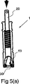
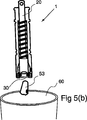
図5(a)および5(b)は、アンプルヘッドを例えば鋭利物の安全な容器60に排出するために装置1を操作する好適な方法を概略的に示す。図5(a)に示すように、プランジャ20は、円筒状本体10の第1端部に向けて緩やかに押される。この力は、軸21の第2端部を操作する利用者の親指によって容易に加えられ、特に前述の手の姿勢(図6(a)および6(b)を参照して更に記述される)で付与され得る。プランジャ20をOリング30に押付けることで、バネ40によって加えられる力よりも充分に大きい力で、アンプルヘッドの下部がOリングに押付けられる。これによって、アンプルヘッドの通過が可能となる程度に充分にOリング30が変形すなわち伸長する。図5(b)に示すように、アンプルヘッドは、容易に、意図的に、かつ、予測どおりに、鋭利物の適切で安全な容器60内に排出され得る。アンプルヘッドがいったん排出されると、プランジャ20は、平衡の位置で、Oリング30(再び非伸長の状態になる)に対して静止する。容易、意図的かつ予測どおりにアンプルヘッドを鋭利物の安全な容器に排出することは、好ましい形態における重要で安全な特徴である。
FIGS. 5 (a) and 5 (b) schematically show a preferred method of operating the
装置1の操作中における利用者の手の好適な姿勢が図6(a)および6(b)に概略的に図示されている。図6(a)に示すように、利用者は、第1の手の舟状骨(または親指)側を上方にして、第1(左)の手で、アンプル53をほぼ垂直な方向に保持する。このように第1の手の親指61と人差し指62とがアンプル53の頂上の方にあり、中指63と薬指64と小指65とが順次に下方に位置する(薬指64と小指65とは通常はアンプルの下方にあり、アンプルに接触しないため、破線で示されている)。利用者は、第2の手の舟状骨(または親指)側を上方にして、第2(右)の手で、装置1をほぼ垂直な方向に保持する。このように第2の手の親指71と人差し指72とが装置1の頂上の方にあり、中指73と薬指74と小指75とが順次に下方に位置する。手の方向を示すために指先のみが図示されているが、利用者は装置(および/またはアンプル)の保持に手の全体を利用してもよく、これらの物体を指先のみで保持することが、必ずしも推奨または希望されるものでないことは、理解されるべきである。
A preferred posture of the user's hand during operation of the
第2の手の親指71は、望まれるならば、図6(b)に図示されるように、開封動作中にプランジャ20上に配置してもよいが、この場合には、親指によって作用する力が意図せずにプランジャを軸方向に移動させないように注意する必要がある。しかし、装置を保持する手や手の指の大きなモーメントを必要とせずに、また、不自然で困難な手の姿勢を必要とせずに、アンプル50の開封後に、親指を、アンプルヘッドの容易な排出が可能となるようにプランジャ20に向けて容易に移動させ得ることは、理解されるであろう。
The
図6(a)および6(b)に図示されるように、利用者は、装置1の右側に存在し、自身の前方に装置とアンプルとを直接かつ中央に保持していると考えられる。利用者の右手は、図示のように、親指71と指72,73,74,75とが観者に向かって(紙面の外側に)突出した状態で、装置1の背後に位置する。利用者の左手は、図示のように、親指61と指62,63,64,65とが観者から遠くに向けて(紙面内に)突出した状態で、アンプルの前方に位置する。
As shown in FIGS. 6 (a) and 6 (b), it is considered that the user is present on the right side of the
図示された手の方向は、垂直方向の長尺状の物体を各手に保持するのに自然な方向であり、自然な腕の姿勢に繋がることが理解されるであろう。対照的に、手の親指または舟状骨側を下方にした状態に上方の手を維持すると(アンプル本体を一方の手で垂直に保持するとともにアンプルヘッドを他方の手の親指と人差し指との間に保持したアンプル開封処理にて必要となるように)、肘が上昇した無理のある腕の姿勢になる。幾つかの従来の技術のアンプル開封装置を使用すると、利用者が困難の少ない姿勢を実現するためには、ほぼ垂直以外の方向にアンプルを向ける必要があり、開封時にアンプルの内容物をこぼす可能性が増えることになる。 It will be understood that the orientation of the hand shown is a natural direction for holding a vertically long object in each hand, leading to a natural arm posture. In contrast, maintaining the upper hand with the thumb or scaphoid side down (holding the ampoule body vertically with one hand and holding the ampoule head between the thumb and index finger of the other hand) (As required for the ampoule opening process held in the arm), the arm is in an unreasonable arm position. Using several prior art ampoule opening devices, the user needs to point the ampoule in a direction other than nearly vertical to achieve a less difficult posture and can spill the ampoule contents when opening The sex will increase.
Oリング(ただし、異なる構成が使用され得る)のような1個以上のアンプルヘッド保持部材を設けることが望ましく、それらがアンプルヘッドを保持する作用は、開封動作中におけるアンプルヘッドの保持のために装置の外部からアンプルに作用するグリップの圧力を必要としないことが理解されるであろう。これによって、親指と人差し指をアンプルヘッドの近く(何れかの側面上)に配置する必要が無くなり、装置のうちアンプルヘッドが保持される部分を、手のうちの比較的に弱い尺骨側で保持することが可能となる。このように、本装置は、自然で無理のない「サムアップ(thumb up)」ポジションの手で保持され得る。利用者の手の幅とほぼ同じ長さの装置本体を利用することで、アンプルのてこの作用が実現され、利用者の手を装置本体の周囲に無理なく密着させることが可能となり、開封動作中にアンプルネックを両手の近く(両手の間)に配置することが可能となる一方で、本体の第2端部から延びるプランジャ(排出機構)の一部に対する容易なアクセスが維持される。以上の理由から、装置の本体は、約5cmと約15cmとの間の長さであることが望ましく、さらに望ましくは、約8cmから約12cmの間の長さとされる。 It is desirable to provide one or more ampoule head holding members, such as O-rings (although different configurations can be used), the action of holding the ampoule head is for holding the ampoule head during the opening operation. It will be appreciated that grip pressure acting on the ampoule is not required from outside the device. This eliminates the need to place the thumb and index finger near (on either side) of the ampoule head and holds the part of the device where the ampoule head is held on the relatively weak ulna side of the hand. It becomes possible. In this way, the device can be held in the hands of a “thumb up” position that is natural and reasonable. By using the main body of the device that is almost the same width as the user's hand, the lever action of the ampoule is realized, and the user's hand can be brought into close contact with the periphery of the main body of the device. While the ampoule neck can be placed near both hands (between both hands), easy access to a portion of the plunger (discharge mechanism) extending from the second end of the body is maintained. For the above reasons, the body of the device is preferably between about 5 cm and about 15 cm long, and more preferably between about 8 cm and about 12 cm long.
Oリングには非常に弾力があるから、比較的に広い範囲にわたる直径のアンプルヘッドが、装置内に収容および保持され得るという更なる利点がある。これによって、広い範囲にわたるサイズのアンプルをひとつの装置の利用で開封することが可能となる(従来から待望されてきたように、装置が非常に狭い範囲のサイズのアンプルに制限されるよりも望ましい)。 Since the O-ring is very elastic, there is the further advantage that a relatively wide range of diameter ampoule heads can be accommodated and retained in the device. This allows ampoules of a wide range of sizes to be opened with the use of a single device (as desired, rather than limiting the device to a very narrow range of ampoules). ).
多くの変形が可能であることは理解されるであろう。例えば、空洞は、開封動作中に空洞の壁面の一部がアンプルヘッドの上部に接触および作用するように成形され得る。現在のところ、好適な実施形態においては望ましい特徴と考えられるが、装置が略円筒や略対称である必要は必ずしもない。好ましい実施形態において、本体は金属で形成される。本体は、鋳型や旋盤で形成された鋼やアルミニウムであり得る。別の形態において、本体は、適切なプラスチックから成形(モールド)される。 It will be appreciated that many variations are possible. For example, the cavity can be shaped such that a portion of the cavity wall contacts and acts on the top of the ampoule head during the opening operation. At present, this is considered a desirable feature in the preferred embodiment, but the device need not be substantially cylindrical or substantially symmetric. In a preferred embodiment, the body is made of metal. The body can be steel or aluminum formed with a mold or a lathe. In another form, the body is molded from a suitable plastic.
別の態様100が図7(a),7(b)および7(c)に図示されている。装置100は、小型のアンプルヘッド150を収容する小型の空洞111を一方の端部に形成し、大型のアンプルヘッド151を収容する大型の空洞112を他方の端部に形成する本体110を具備する。空洞111には小型の保持部材130が付随し、空洞112には大型の保持部材131が付随する。これによって、サイズが広い範囲にわたる複数のアンプルにひとつの装置100を利用することが可能となる。本体110の内部で移動可能なのは、排出部材120である。排出部材120は、大型の空洞112(図7(a)に示される)または小型の空洞111(図7(c)に示される)からアンプルヘッドを排出するために、利用者の親指が操作部121に接触することで操作される。操作部121は、排出部材120の軸に対してほぼ垂直に伸び、本体110の軸上の中央部におけるスロット113を介して突出する。図7(b)は、排出部材120の中間の位置を図示する。
Another
装置200の形態をとる別の変形例が図7(d)に図示されている。この形態は、ひとつの排出部材を持つのではなく、各々が保持部材230および231に向けてそれぞれ付勢される第1および第2の排出部材220aおよび220bを備える点を除いて、形態100に類似する。これによって、アンプルヘッドをより予測どおりに接触させることや、アンプルヘッドの排出に先立って排出部材と保持部材との間にアンプルヘッドをより予測どおりに保持することが可能となる。図示された形態においては、バネなどの弾性部材240によって、排出部材220aおよび220bの間に付勢力が付与される。しかし、任意の適切な代替の機構が利用され得る。
Another variation taking the form of the
保持部材は、Oリングや或る程度の固有の弾性を持つ類似の要素(クアッドリング(quad ring)や可撓性のワッシャなど)であることが現段階では好ましいが、Oリング以外の保持構成も利用され得る。 The holding member is preferably an O-ring or a similar element having a certain degree of inherent elasticity (such as a quad ring or a flexible washer). Can also be used.
プランジャ以外の排出機構も採用され得る。 A discharging mechanism other than the plunger can also be employed.
例えば、他の形態においては、幾つかの分割された保持部材が、本体部内の空洞の周囲に角度上の間隔をあけて設けられる。バネで内向きに付勢され、空洞の内壁面の小さい複数の窪み内に設置された複数の小型のボールベアリングが利用され得る。 For example, in another form, several divided retaining members are provided at angular intervals around a cavity in the body. A plurality of small ball bearings biased inwardly by a spring and installed in a plurality of small depressions on the inner wall surface of the cavity can be used.
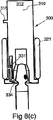
ひとつの形態(300で概略的に示されるとともに図8(a)から8(c)に図示される)は、複数の分割された保持部材を備え、そのうちのひとつが示されている。 One form (schematically indicated at 300 and shown in FIGS. 8 (a) to 8 (c)) comprises a plurality of divided holding members, one of which is shown.
保持部材は、概ね凹部314内に位置する弾性的な可撓性の保持要素331の形態をとる。可撓性の保持要素331の第1の端部は、凹部314内の固定の位置にあり、第2の端部334は、アンプルヘッド受容スペース311内に弾性的に突出し得るように設けられて、アンプルのヘッドに接触する。
The retaining member takes the form of an elastic
可撓性の保持要素331における突出部335は、装置300の外側に突出する。軸方向に移動可能なカラー(collar)は、円筒状部材321の形態をとり、装置の本体部310における円筒状の外周面の周囲に広がり、突出部335に接触しない非動作位置(図8(a)に図示される)と、突出部335に接触する動作位置との間で移動可能である。
A
円筒部材321が突出部335に接触すると(図8(b)および8(c)に図示されるように)、第2の端部334がアンプルヘッド受容スペース311内に突出するように、可撓性の保持要素331が内側に押される。この構成においては、図8(a),(b)および8(c)や装置1に関する前掲の記載の参照から明らかとなる方法で、可撓性の保持要素331(より正確には、複数の可撓性の保持要素の組合せ)がアンプルヘッドを受容および保持する。
When the
円筒状部材321が突出部335に接触しない場合(図8(a)に図示されるように)、可撓性の保持要素331における第2の端部334は内側に押されず、アンプルヘッド受容スペース311内には概ね突出しない。
If the
装置300を利用するために、利用者は、まず、円筒状部材321を動作位置(図8(b)および8(c)に図示される)に移動し、アンプルヘッドを挿入するとともに装置1について前述したようにアンプルを分断することで、装置を操作する。アンプルヘッドは、アンプルの残りの部分から取り外された後、ひとつまたは複数の可撓性の保持要素331によってアンプルヘッド受容スペース311内に保持される。
In order to use the
アンプルヘッドを排出するために、利用者は、装置300をほぼ直立の方向に保持し、本体部310を円筒状部材321に対して下方に移動する。これは、手のひらや手の1本以上の指で円筒状部材321を保持するとともに、同じ手の親指で本体部310の上面部312を下方に押すことで容易に実現される。これによって、可撓性の保持要素331は、図8(a)に示すように非動作位置に戻り、これによって、アンプルヘッドは、もはや保持されなくなって、アンプルヘッド受容スペースから重力によって落下する。
In order to eject the ampoule head, the user holds the
本体部310に対する円筒状部材321の軸上の移動は、例えば本体部310の迫出し部(abutment)315,316によって制限される。
The axial movement of the
摩擦または迫出し部のような手段が、非動作位置に押されるように特に操作された場合を除いて、円筒状部材321を動作位置に保持するのに役立つように設けられ得ることが理解されるであろう。代わりに、または加えて、円筒状部材321を動作位置に移動させる操作を利用者が実行する必要が無いように、また、積極的な排出動作が使用時に付与されるように、円筒状部材321は、動作位置に向けて付勢され得る。
It will be appreciated that means such as a friction or squeeze may be provided to help hold the
本実施形態において、排出機構は、1個以上の保持要素による少なくとも一部分と、適切に操作された場合にアンプルヘッドがもはや保持部材によってアンプルヘッド受容スペースに保持されなくなるように1個以上の保持要素に作用する(または作用を止める)装置の他の部分とで、実現されることが理解されるであろう。 In this embodiment, the ejection mechanism includes at least a portion of the one or more holding elements and the one or more holding elements such that when properly operated, the ampoule head is no longer held in the ampoule head receiving space by the holding member. It will be understood that this is realized with other parts of the device that act on (or stop acting).
更なる実施形態が図9(a)から11に図示され、400で概略的に示される。装置400は、本体部(本実施形態においては概ねピストル型の本体410)を具備する。装置400は、アンプルヘッドを受容するための開口部411を画定する拡大部412を第1の端部に有し、本体410の約半分の長さにわたるハンドル部440を第2の端部に有する。略中央部450は、ハンドル部440と拡大部412との間に設けられて両者を連結する。
A further embodiment is illustrated in FIGS. 9 (a) to 11 and is shown schematically at 400. FIG. The
装置400は、本実施形態においては本体410から分離して形成されてアンプルヘッド係合要素434の形態をとる、少なくともひとつのアンプルヘッド保持部材を更に有する。アンプルヘッド係合要素434と拡大部412の壁面415に位置するアンプルヘッド係合部414との間にアンプルヘッドが把持され得るように、アンプルヘッド係合要素434は、開口部411内で移動可能である。
The
装置400は、本実施形態では解放要素420として設けられたアンプルヘッド解放機構(所望の時点でアンプルヘッドの排出を可能にする)を更に有する。解放要素420は、アンプルヘッド係合要素434に連結され、アンプルヘッド係合要素434を拡大部412に対して移動させるために、中央部450に対して移動可能である。解放要素420は、中央部450における空洞452内に部分的に位置する。解放要素420は、本実施形態では空洞452内に位置するつる巻バネ457の形態をとる弾性部材によって、アンプルヘッド係合部414と壁415とに向けて付勢される。解放要素420は、中央部450の頂上面から上方に突出するとともに解放要素420を所望のように移動するために使用され得る操作部422を備える。操作部422は、利用者の手がハンドル部440にて装置を保持している場合に、手の親指での操作にとって適切な位置にある。
The
アンプルヘッド53は、アンプルヘッド係合要素434とアンプルヘッド係合部414との間に挿入され、アンプルヘッド係合要素434と解放要素420とが、アンプルヘッド係合部414から僅かに離れるようにアンプルヘッドによって押されることが理解されるであろう。アンプルヘッド上の目印55(アンプルネックの弱い部分の位置を示す)が、装置400上の概ね側面の中央の位置に設けられた目印446に合うように、アンプルヘッド53は好適に挿入される。そして、アンプルヘッド53は、図10(a)および10(b)に示すように、解放要素420に作用する付勢力によって、アンプルヘッド係合要素434とアンプルヘッド係合部414との間に保持される。
The
アンプル本体51および装置400の双方は、使用中に、手における尺骨または小指側よりも高い舟状骨または親指側で好適に保持されることが理解されるであろう。アンプルは、装置400とアンプル本体51との相対的な回転で開封され得る(例えば図10(b)に大きい矢印で図示された方向)。そして、アンプルヘッド53は、図11に図示されるように、アンプルヘッド係合要素434が後退させられるまで保持される。この後退は、装置を保持する手の親指を使って操作部422を拡大部412から離れる方向にスライドさせることで、利用者によって容易に達成され得る。
It will be appreciated that both
開封動作の実行中に、アンプルヘッドからの反力によって、アンプルヘッド係合要素434がアンプルヘッド係合部414から離れる方向に過度に後退すると、開封動作が妨げられまたは止められ得る。そのような不適切な後退を防ぐために後退制限機構が設けられ得る。
If the ampoule head engaging element 434 is excessively retracted in the direction away from the ampoule
バネ457によって加えられる付勢力は、装置の外形と、アンプルヘッド係合要素434およびアンプルヘッド係合部414の間にアンプルヘッド53が密着するようになされた両者の外形の形成とに相俟って、開封動作中にアンプルヘッド係合要素434がアンプルヘッド係合部414から不適切に後退することを防ぐのに充分となり得る。この場合、不適切な後退を防ぐための更なる後退制限機構は不要であり、その装置は、図13に図示されるように形態600の形をとり得る(図9(a)から11の形態と類似するが、以下に説明する後退制限機構を持たない)。後退制限機構が必要ならば、図9(a)から11に示されるような機構が設けられ得る。
The biasing force applied by the
図9(a)から11に図示されるように、解放要素420の下側には、下方に突出する複数のラチェット状(ratchet-like)の歯部442が設けられる。ラチェット状の歯部422は、空洞452の底面上に設けられて上方に突出する1個以上のラチェット状の歯部455と相互に作用するようになされる。下方に突出するラチェット状の歯部422が上方に突出する1個以上のラチェット状の歯部455に作用すると、アンプルヘッド係合要素434の後退(すなわち、図9(a)や10(a)の図示における左方への移動)が妨げられる。しかし、本実施形態においては、解放要素420が空洞452内に少し緩く設置されており、アンプルヘッドがアンプル受容スペースに挿入されると、アンプルヘッドは、上方に向かう小さい力をアンプルヘッド係合要素434に付与することが理解されるであろう。この力は、下方に突出する歯部422を、上方に突出する1個以上のラチェット状の歯部455から離れる方向に、両者が相互に作用しないように持ち上げるのに充分である。このように、アンプルヘッド係合要素434の後退は、アンプルヘッドの挿入中には妨げられない。しかし、開封動作中においては、アンプルヘッドは、下方に向かう反力の成分をアンプルヘッド係合要素434に付与し、したがって、下方に突出する歯部422は、上方に突出する1個以上のラチェット状の歯部455と相互に作用する。このように、アンプルヘッド係合要素434の後退は、開封動作中には妨げられる。
As shown in FIGS. 9 (a) to 11, a plurality of ratchet-like teeth 442 projecting downward are provided below the
下方に突出する支点427が、軸上における操作部422とラチェット状の歯部422との間において、解放機構420に設けられる。したがって、操作部422が利用者の親指で下方に押されると、ラチェット状の歯部422はラチェット状の歯部455から離れる方向に持ち上げられ、解放要素420は、歯部422,455からの抵抗がない状態で移動し得る。これによって、アンプルヘッドの容易な解放/排出が可能となる。本実施形態において、後退制限機構は、利用者による他の操作を必要とせず、利用者が装置を操作する時に必要に応じて動作することが理解されるであろう。
A downwardly projecting
図12は、別の後退制限機構を持つ形態500を図示する。その後退制限機構においては、利用者が解放部材523を押し下げた場合を除き、アンプルヘッド係合要素534が後退することは概ね妨げられる。形態500は、多くの点で形態400に類似し、対応する部分を示すために同じ名称(ただし、最初の数値が4ではなくて5であるから、参照番号は異なる)が使用される。解放部材が押し下げられた場合を除いてアンプルヘッド係合要素の後退を防止または制限する多くの方法があることは明らかであり、任意の適切な変形が利用され得る。
FIG. 12 illustrates a
形態500において、解放部材523は、解放要素520の操作部522に設けられる。キャッチ部材524は、解放要素520に装着され、バネ528によって下方に付勢され、空洞521に設けられた複数の窪み(indentations)551のひとつに係合し、解放部材523が押されていない場合に解放要素520の後退を妨げる。解放部材523が押されると、解放部材523に連結されたキャッチ部材524は上方に移動するとともに窪み551から取り出されて、解放要素520の移動とアンプルヘッド係合要素534の後退とが可能となり、アンプルヘッドの解放および排出が許可される。
In the
図14(a)から14(f)は、図9から13に図示されたタイプの装置の動作を概略的に図示する。 FIGS. 14 (a) to 14 (f) schematically illustrate the operation of an apparatus of the type illustrated in FIGS. 9 to 13. FIG.
図14(a)は、アンプルの挿入前の装置を示す。図14(b)は、アンプルヘッドが部分的に装置に挿入された状態の装置およびアンプルを示す。図14(c)は、アンプルの開封の直前にアンプルヘッドが装置内に挿入された状態の装置およびアンプルを示す。図14(d)は、アンプルの開封の直後における装置およびアンプルを示す。図14(e)は、装置内に保持された取り外し済みのアンプルヘッドを示す。図14(f)は、取り外されたアンプルヘッドが装置から解放/排出された直後における装置および取り外し済みのアンプルヘッドを示す。 FIG. 14 (a) shows the device before the ampoule is inserted. FIG. 14 (b) shows the device and ampoule with the ampoule head partially inserted into the device. FIG. 14 (c) shows the device and ampoule with the ampoule head inserted into the device immediately before opening the ampoule. FIG. 14 (d) shows the device and ampoule immediately after opening the ampoule. FIG. 14 (e) shows the removed ampoule head held in the apparatus. FIG. 14 (f) shows the device and the removed ampoule head immediately after the removed ampoule head is released / discharged from the device.
Aで示される矢印は、解放要素に作用する付勢力を示す。Bで示される矢印は、アンプルおよび/またはアンプルヘッドの移動の方向を示す。Cで示される矢印は、アンプルヘッドが挿入されるときの解放要素の移動の方向を示す。Dで示される矢印は、アンプルの開封動作中に、アンプルヘッド係合要素および解放要素の望ましくない後退を防ぐために、利用者の親指によって、(後退制限機構が含まれないまたは充分でない幾つかの変形例において)加えられ得る力を示す。Eで示される矢印は、アンプルの開封動作の最中または直後にアンプルに対して装置が移動し得る方向を示す。Fで示される矢印は、利用者の親指によって操作部に加えられる力と、アンプルヘッド(矢印G)を解放/排出させるための解放要素の移動の方向とを示す。 The arrow indicated by A indicates the biasing force acting on the release element. The arrow indicated by B indicates the direction of movement of the ampoule and / or ampoule head. The arrow indicated by C indicates the direction of movement of the release element when the ampoule head is inserted. The arrow indicated by D indicates that the user's thumb may prevent undesired retraction of the ampoule head engaging element and the release element during the opening operation of the ampoule (some retraction limiting mechanisms are not included or not sufficient). In a variant) shows the force that can be applied. The arrow indicated by E indicates the direction in which the device can move relative to the ampoule during or immediately after the ampoule opening operation. The arrow indicated by F indicates the force applied to the operating portion by the user's thumb and the direction of movement of the release element for releasing / ejecting the ampoule head (arrow G).
図15は、使用中に装置上にある利用者の親指71と指72,73,74,75との相対的な位置を一例として示す。
FIG. 15 shows as an example the relative positions of the user's
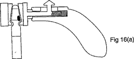
図16(a)および16(b)は、開封の直前に、異なるサイズのアンプルのヘッドを収容する、図9から13に図示されたタイプの装置を示す。 FIGS. 16 (a) and 16 (b) show a device of the type illustrated in FIGS. 9 to 13 that accommodates different sized ampoule heads just prior to opening.
前掲の用語は説明を目的とするものであって、限定としてみなされるべきでないことは、理解されるであろう。 It will be understood that the above terms are for illustrative purposes and should not be considered limiting.
前述の複数の実施形態は、発明を例示することを意図したものであり、本発明の範囲が、説明および図示された細かい構造や動作に限定されず、後述のクレームのみによって規定されることは、理解されるであろう。 The foregoing embodiments are intended to exemplify the present invention, and the scope of the present invention is not limited to the detailed structures and operations described and illustrated, but is defined only by the following claims. Will be understood.
後述のクレームおよび前述の本発明の説明においては、明示または否定し得ない暗示に伴って文脈が別の解釈を必要とする場合を除いて、「具備する(comprise)」という文言や("comprises"や"comprising"といった)変形は包含的(inclusive)な意味に、すなわち、記述された特徴の存在を示すためであって、本発明の様々な形態における更なる特徴の存在や追加を排除するためではなく、使用される。 In the claims that follow and in the description of the invention above, the word “comprises” or “comprises” unless the context requires a different interpretation with explicit or non-denying implications. Variations (such as "and" comprising ") are in an inclusive sense, i.e. to indicate the presence of the described feature, and exclude the presence or addition of additional features in various forms of the invention. Used for rather than for.
ここでは先行技術の刊行物を参照したが、この参照によっては、これらの文献の何れかが、オーストラリアや他の任意の国における当該分野で広く知られた一般的な知識の一部を構成する、と認めたことにはならない。 References have been made here to prior art publications, depending on which reference any of these documents forms part of the general knowledge widely known in the field in Australia or any other country. I don't admit that.
1,100,200,300,400,500,600……アンプル開封器、50……アンプル、
1,100,200,300,400,500,600 ... Ampoule opening device, 50 ... Ampoule,
Claims (9)
使用時に手で保持される本体部であって、前記アンプルの前記ヘッド部の少なくとも一部分をその内部に受容する空洞と、前記空洞のうち当該本体部の一端側に位置する入口の近傍の内壁面に形成された環状の溝部とを有する本体部と、
前記本体部における前記溝部内に配置され、前記ヘッド部が前記空洞内に挿入された後に、当該ヘッド部を少なくとも部分的に前記空洞内に保持する保持具と、
前記空洞内に保持された前記アンプルの前記ヘッド部に接触するとともに当該ヘッド部を前記空洞から排出する排出機構とを具備し、
前記保持具は、力を加えない時の最大寸法が前記ヘッド部の最大幅の部分よりも小さくて弾性的に拡大可能な開口部を含み、弾性材料からなるOリングの形態で弾性的に伸長可能な環状の機構であり、
前記保持具は、前記ヘッド部が前記空洞内に挿入された場合に少なくとも前記ヘッド部の最大幅の部分が前記開口部を通過し、かつ、前記ヘッド部が当該保持具を通過することで前記保持具が拡大してから、前記ヘッド部の最大幅の部分の下側にて自動的に収縮して前記ヘッド部を少なくとも部分的に前記空洞内に解放可能に保持するように、前記本体部に設置され、
使用時に、(a)前記ヘッド部を少なくとも部分的に前記空洞内に保持する前記本体部と、(b)前記アンプルの残りの部分と、の相対的な移動によって、前記ヘッド部は、前記アンプルの残りの部分から取り外し可能であり、
前記取り外されたヘッド部が、前記排出機構に接触するとともに前記排出機構によって前記空洞から排出されることで当該装置の再利用が可能である
装置。 A reusable hand-held device for opening an ampoule of the type having a removable head,
A main body portion held by hand when in use, a cavity for receiving at least a part of the head portion of the ampoule therein, and an inner wall surface in the vicinity of an inlet located on one end side of the main body portion of the cavity A main body having an annular groove formed in
A holder that is disposed within the groove portion of the body portion and holds the head portion at least partially within the cavity after the head portion is inserted into the cavity;
A discharge mechanism for contacting the head part of the ampoule held in the cavity and discharging the head part from the cavity;
The holder includes an opening that is elastically expandable with a maximum dimension when no force is applied, which is smaller than the maximum width of the head portion, and elastically expands in the form of an O-ring made of an elastic material A possible annular mechanism,
When the head portion is inserted into the cavity, at least a portion of the maximum width of the head portion passes through the opening, and the head portion passes through the holding tool when the head portion is inserted into the cavity. The body portion so as to automatically contract under the maximum width portion of the head portion after the retainer has expanded to at least partially releasably retain the head portion within the cavity. Installed in
In use, (a) the head portion is moved by the relative movement of the body portion at least partially holding the head portion in the cavity, and (b) the remaining portion of the ampule, so that the head portion Is removable from the rest of the
The detached head portion, it is possible to reuse of the device in which is discharged from the cavity by the ejecting mechanism while contacting the ejection mechanism device.
請求項1に記載の装置。 The inner diameter of the annular groove is larger than the outer diameter of the holder so that a space is formed between the outer peripheral surface of the holder and the inner peripheral surface of the annular groove. The device of claim 1, wherein the device is extensible.
前記長尺部材は、前記空洞内に保持された前記アンプルの前記ヘッド部に接触するとともに前記保持具の作用に抗して前記ヘッド部を前記空洞から排出するように、手動で操作される
請求項1または請求項2に記載の装置。The discharge mechanism has a long member movable within the main body,
The long member is manually operated so as to contact the head portion of the ampoule held in the cavity and discharge the head portion from the cavity against the action of the holder. The apparatus of Claim 1 or Claim 2.
更に、前記長尺部材は、前記アンプルの前記ヘッド部に接触するとともに前記ヘッド部の取り外し後に当該ヘッド部を前記空洞の入口に対して中央部に保持するようになされた凹部を端部に有する
請求項3に記載の装置。The elongate member is resiliently biased toward the entrance of the cavity in the body and has an axis generally aligned with the center of the entrance of the cavity;
Furthermore, the long member has a recess at the end that is in contact with the head portion of the ampoule and that holds the head portion in the center with respect to the entrance of the cavity after the head portion is removed. The apparatus of claim 3.
請求項1から請求項4の何れかに記載の装置。The apparatus according to any one of claims 1 to 4, wherein the main body has a generally long cylindrical shape.
請求項5に記載の装置。The apparatus according to claim 5, wherein the main body has a cavity at each axial end, and the cavity at one end is different in size from the cavity at the other end.
請求項5または請求項6に記載の装置。The apparatus according to claim 5, wherein the outer peripheral surface of the main body has a flat portion extending in a longitudinal direction along the axis so that the main body does not freely rotate around the axis.
前記アンプルの前記ヘッド部を受容する空洞と、前記空洞のうち当該本体部の一端側に位置する入口の近傍に形成された環状の溝部とを有する略円筒状の本体部と、
力を加えない時の最大寸法が前記ヘッド部の最大幅の部分よりも小さい開口部を有し、弾性的に伸長可能なOリングとを具備し、
前記Oリングは、前記本体部における前記溝部内に配置され、前記ヘッド部が前記空洞内に挿入された場合に、少なくとも前記アンプルにおける前記ヘッド部の前記最大幅の部分が前記開口部を通過できるように前記溝部内で外側に伸長し得るように、力を加えない状態で前記溝部の内径よりも小さい外径を有し、
前記Oリングは、前記ヘッド部が当該Oリングを通過することで拡大してから、前記ヘッド部の最大幅の部分の下側にて自動的に収縮し、
前記ヘッド部を収容する前記本体部と前記アンプルの残りの部分との間の相対的な移動によって前記ヘッド部が前記アンプルの残りの部分から取り外された後、前記ヘッド部は、前記Oリングによって前記空洞内に保持され、
前記本体部内にて移動可能な長尺部材を更に具備し、前記空洞の入口に向けてバネにより弾性的に付勢され、前記長尺部材が、前記アンプルの前記ヘッド部に接触するとともに前記Oリングを介して前記ヘッド部を前記空洞から排出するように手動で操作されることで当該装置の再利用が可能である
ことを特徴とする装置。 A reusable hand-held device for opening an ampoule of the type having a removable head,
A substantially cylindrical body having a cavity for receiving the head part of the ampoule, and an annular groove formed in the vicinity of an inlet located on one end side of the body part of the cavity ;
An O-ring having an opening that has a smaller maximum dimension when no force is applied than a portion of the maximum width of the head portion and is elastically stretchable,
The O-ring is disposed in the groove portion in the main body portion, and when the head portion is inserted into the cavity, at least the maximum width portion of the head portion in the ampoule can pass through the opening. So that the outer diameter is smaller than the inner diameter of the groove portion without applying force so that it can extend outward in the groove portion,
The O-ring expands automatically when the head portion passes through the O-ring, and then automatically contracts below the maximum width portion of the head portion.
After the head portion is removed from the remaining portion of the ampoule by relative movement between the main body portion that houses the head portion and the remaining portion of the ampule, the head portion is moved by the O-ring. Retained in the cavity,
The O together with further comprising an elongate member movable in the said body portion being resiliently biased by a spring toward the entrance of the cavity, the elongate member is in contact with the head portion of the ampoule The apparatus can be reused by being manually operated so as to eject the head part from the cavity through a ring.
前記ヘッド部を最も高くした状態で前記アンプルを第1の手に保持し、
(i)下端部にて前記アンプルの前記ヘッド部を受容する空洞、および、前記空洞の入口の近傍の内壁面に形成された環状の溝部と、(ii)前記溝部内に配置され、前記ヘッド部が前記空洞内に挿入された後に前記ヘッド部を少なくとも部分的に前記空洞内に保持する保持具であって、力を加えない時の最大寸法が前記ヘッド部の最大幅の部分よりも小さくて弾性的に拡大可能な開口部を含み、弾性材料からなるOリングの形態で弾性的に伸長可能な環状の機構である保持具と、(iii)当該アンプル開封器の内部で移動可能な長尺部材と、を有するアンプル開封器を、親指を最も高くした状態で他方の手に保持し、
少なくとも前記ヘッド部の最大幅の部分が前記開口部を通過し、かつ、前記保持具が、前記ヘッド部が内部を通過することで拡大してから、前記ヘッド部の最大幅の部分の下側にて自動的に収縮して前記ヘッド部を少なくとも部分的に前記空洞内に解放可能に保持するように、前記アンプルの前記ヘッド部を少なくとも部分的に前記空洞内に挿入し、
前記ヘッド部を内部に保持する前記アンプル開封器と前記アンプルの残りの部分との相対的な移動を発生させることで、前記ヘッド部を前記アンプルの残りの部分から取り外し、
前記空洞内に保持された前記アンプルの前記ヘッド部に接触するとともに前記保持具の作用に抗して前記ヘッド部が前記空洞から排出されるように前記長尺部材を手動で操作することで当該装置を再利用し得る
方法。A method of opening an ampoule of the type having a removable head part,
Hold the ampoule in the first hand with the head portion in the highest position,
(I) a cavity for receiving the head part of the ampoule at the lower end part , and an annular groove part formed on an inner wall surface in the vicinity of the inlet of the cavity ; and (ii) the head disposed in the groove part. A holder that holds the head portion at least partially within the cavity after the portion is inserted into the cavity, wherein the maximum dimension when no force is applied is smaller than the maximum width portion of the head portion And a holder that is an annular mechanism that is elastically expandable in the form of an O-ring made of an elastic material, and (iii) a length that is movable within the ampoule opening device. An ampoule opening device having a scale member, and holding the other hand with the thumb at the highest position,
At least a portion of the maximum width of the head portion passes through the opening, and the holding member expands by passing the inside of the head portion, and then a lower side of the maximum width portion of the head portion Inserting the head portion of the ampoule at least partially into the cavity so as to automatically retract and at least partially releasably hold the head portion within the cavity;
Removing the head part from the remaining part of the ampoule by generating a relative movement between the ampoule opening device holding the head part inside and the remaining part of the ampoule;
The by manipulating the elongate member such that said head portion against the action of the retainer is discharged from the cavity as well as in contact with the head portion of the ampoule is held in the cavity manually A method by which equipment can be reused .
Applications Claiming Priority (3)
| Application Number | Priority Date | Filing Date | Title |
|---|---|---|---|
| AU2006903449 | 2006-06-27 | ||
| AU2006903449A AU2006903449A0 (en) | 2006-06-27 | Apparatus and method for opening ampoules | |
| PCT/AU2007/000894 WO2008000030A1 (en) | 2006-06-27 | 2007-06-27 | Apparatus and method for opening ampoules |
Publications (3)
| Publication Number | Publication Date |
|---|---|
| JP2009541163A JP2009541163A (en) | 2009-11-26 |
| JP2009541163A5 JP2009541163A5 (en) | 2010-08-12 |
| JP5085647B2 true JP5085647B2 (en) | 2012-11-28 |
Family
ID=38845039
Family Applications (1)
| Application Number | Title | Priority Date | Filing Date |
|---|---|---|---|
| JP2009516823A Active JP5085647B2 (en) | 2006-06-27 | 2007-06-27 | Device and method for opening ampoules |
Country Status (6)
| Country | Link |
|---|---|
| US (2) | US20090277941A1 (en) |
| EP (1) | EP2038203B1 (en) |
| JP (1) | JP5085647B2 (en) |
| CN (1) | CN101479181B (en) |
| AU (1) | AU2007264404B2 (en) |
| WO (1) | WO2008000030A1 (en) |
Families Citing this family (7)
| Publication number | Priority date | Publication date | Assignee | Title |
|---|---|---|---|---|
| AU2010220720A1 (en) * | 2009-03-03 | 2011-09-08 | Cezary Pluska | Apparatus for breaking off the head of a glass ampoule |
| CN101804955B (en) * | 2010-01-13 | 2014-06-25 | 李发修 | Medical ampoule mouth gag |
| US9457401B2 (en) * | 2012-05-24 | 2016-10-04 | LGT Manufacturing Co., Inc. | Riser breaker assembly |
| TWI511915B (en) * | 2013-01-16 | 2015-12-11 | Safe ampoule opener | |
| DK178691B1 (en) * | 2015-04-27 | 2016-11-14 | Mads Ingerslev Lotzfeldt | Ampoule opener |
| US11013340B2 (en) | 2018-05-23 | 2021-05-25 | L&P Property Management Company | Pocketed spring assembly having dimensionally stabilizing substrate |
| KR102518964B1 (en) * | 2019-06-14 | 2023-04-05 | 서해식 | Vertical bottle opener with an opener at the bottom of the handle |
Family Cites Families (21)
| Publication number | Priority date | Publication date | Assignee | Title |
|---|---|---|---|---|
| US2317420A (en) * | 1940-12-20 | 1943-04-27 | American Can Co | Container |
| US2638022A (en) * | 1952-02-15 | 1953-05-12 | Reyes Severo | Ampoule breaker |
| US2865524A (en) * | 1956-09-13 | 1958-12-23 | Sterling Drug Inc | Sterile ampule package |
| US3544020A (en) * | 1968-10-03 | 1970-12-01 | West Laboratories Inc | Finger protector for use in the opening of ampoules |
| US3720250A (en) * | 1970-11-02 | 1973-03-13 | West Laboratories Inc | Safety device when opening ampoules |
| US3749271A (en) * | 1971-06-22 | 1973-07-31 | Becton Dickinson Co | Resealable ampoule closure |
| AR204599A1 (en) * | 1975-08-21 | 1976-02-12 | Ims Ltd | BRAND NEW HAND TOOL FOR MANUAL OR DIGITAL BREAKING OF SEALED GLASS AMPOULES |
| US4226376A (en) * | 1978-10-12 | 1980-10-07 | Pfleger Frederick W | Ampule breaker |
| CA1140094A (en) | 1980-10-30 | 1983-01-25 | Ghislain Vivier | Ampoule breaker |
| US4353869A (en) * | 1981-01-09 | 1982-10-12 | Guth Richard U | Ampoule assembly and holder |
| US4437690A (en) * | 1981-09-23 | 1984-03-20 | Drath Edwin H | High pressure hose swivel connector |
| US4506817A (en) * | 1981-12-23 | 1985-03-26 | Parker Andrew E | Device for opening ampoules |
| US4508250A (en) * | 1983-04-11 | 1985-04-02 | Kathleen Punchak | Ampoule breaker tool |
| JP2552882B2 (en) * | 1987-09-12 | 1996-11-13 | 博章 三輪 | Ampoule cutter |
| US5222951A (en) * | 1992-04-13 | 1993-06-29 | Leonard Bloom | Guarded skin hook for surgical use |
| AT404827B (en) * | 1994-07-28 | 1999-03-25 | Avl Verbrennungskraft Messtech | METHOD AND DEVICE FOR REMOVING A LIQUID FROM A SEALED GLASS AMULET |
| US6244487B1 (en) * | 1999-01-22 | 2001-06-12 | William M. Murray | Safety ampule breaker |
| US6257474B1 (en) * | 1999-06-07 | 2001-07-10 | Don R. Jones | Ampoule opener |
| US6832703B1 (en) * | 2003-05-20 | 2004-12-21 | Howmedica Osteonics Corp. | Monomer vial breaker |
| DE202004012367U1 (en) * | 2004-08-06 | 2004-10-07 | Tecpharma Licensing Ag | Absorbent seal for 2-chamber ampoule |
| US7946461B2 (en) * | 2006-06-05 | 2011-05-24 | Watson Laboratories, Inc. | Ampoule opener and associated methods |
-
2007
- 2007-06-27 AU AU2007264404A patent/AU2007264404B2/en active Active
- 2007-06-27 CN CN2007800241627A patent/CN101479181B/en active Active
- 2007-06-27 WO PCT/AU2007/000894 patent/WO2008000030A1/en active Application Filing
- 2007-06-27 US US12/306,651 patent/US20090277941A1/en not_active Abandoned
- 2007-06-27 EP EP20070719132 patent/EP2038203B1/en active Active
- 2007-06-27 JP JP2009516823A patent/JP5085647B2/en active Active
-
2015
- 2015-09-24 US US14/864,244 patent/US20160031692A1/en not_active Abandoned
Also Published As
| Publication number | Publication date |
|---|---|
| US20090277941A1 (en) | 2009-11-12 |
| CN101479181B (en) | 2013-01-16 |
| JP2009541163A (en) | 2009-11-26 |
| AU2007264404A1 (en) | 2008-01-03 |
| EP2038203B1 (en) | 2012-08-15 |
| US20160031692A1 (en) | 2016-02-04 |
| EP2038203A1 (en) | 2009-03-25 |
| WO2008000030A1 (en) | 2008-01-03 |
| AU2007264404B2 (en) | 2011-01-27 |
| EP2038203A4 (en) | 2011-11-09 |
| CN101479181A (en) | 2009-07-08 |
Similar Documents
| Publication | Publication Date | Title |
|---|---|---|
| JP5085647B2 (en) | Device and method for opening ampoules | |
| US5195982A (en) | Hypodermic needle and protective cap handling method | |
| US4986817A (en) | Hypodermic syringe sheath holder and needle guide | |
| JP7028949B2 (en) | Cap for medical injector | |
| US20070016140A1 (en) | Exchangeable safety needle assembly | |
| US4921489A (en) | Hypodermic needle shield | |
| JP2021521913A (en) | Pen needle assembly device | |
| US5069667A (en) | Device for effecting safe removal of a used needle | |
| NO885709L (en) | Aerosol dispenser. | |
| US20220031959A1 (en) | Pen needle apparatus | |
| EP4353612A2 (en) | Gripping attachment for a bottle | |
| CN211444987U (en) | Ampoule opening device with adjustable | |
| AU2007301738A1 (en) | Needle safety device | |
| JPH06510510A (en) | hand held equipment | |
| CN209378203U (en) | Needle assembles equipment | |
| CA2531712A1 (en) | Disposable safety needle rack system for syringe | |
| CN220520100U (en) | Ampoule drawing liquid protector | |
| US11744957B2 (en) | Pen needle assembly apparatus | |
| CN109966596B (en) | Pen needle assembling equipment | |
| CN219751888U (en) | Medical bottle opening device | |
| GB2253618A (en) | Implement for removing caps from drinking-bottles | |
| US8051726B2 (en) | Liquid handling equipment | |
| US9480622B1 (en) | Medical device safety holder | |
| US8715249B2 (en) | Trocar safety cap | |
| CN109607451A (en) | A kind of ampoule bottle opener |
Legal Events
| Date | Code | Title | Description |
|---|---|---|---|
| A521 | Request for written amendment filed |
Free format text: JAPANESE INTERMEDIATE CODE: A523 Effective date: 20100621 |
|
| A621 | Written request for application examination |
Free format text: JAPANESE INTERMEDIATE CODE: A621 Effective date: 20100621 |
|
| A131 | Notification of reasons for refusal |
Free format text: JAPANESE INTERMEDIATE CODE: A131 Effective date: 20120221 |
|
| A977 | Report on retrieval |
Free format text: JAPANESE INTERMEDIATE CODE: A971007 Effective date: 20120223 |
|
| A521 | Request for written amendment filed |
Free format text: JAPANESE INTERMEDIATE CODE: A523 Effective date: 20120514 |
|
| TRDD | Decision of grant or rejection written | ||
| A01 | Written decision to grant a patent or to grant a registration (utility model) |
Free format text: JAPANESE INTERMEDIATE CODE: A01 Effective date: 20120807 |
|
| A01 | Written decision to grant a patent or to grant a registration (utility model) |
Free format text: JAPANESE INTERMEDIATE CODE: A01 |
|
| A61 | First payment of annual fees (during grant procedure) |
Free format text: JAPANESE INTERMEDIATE CODE: A61 Effective date: 20120905 |
|
| R150 | Certificate of patent or registration of utility model |
Ref document number: 5085647 Country of ref document: JP Free format text: JAPANESE INTERMEDIATE CODE: R150 Free format text: JAPANESE INTERMEDIATE CODE: R150 |
|
| FPAY | Renewal fee payment (event date is renewal date of database) |
Free format text: PAYMENT UNTIL: 20150914 Year of fee payment: 3 |
|
| RD02 | Notification of acceptance of power of attorney |
Free format text: JAPANESE INTERMEDIATE CODE: R3D02 |
|
| R250 | Receipt of annual fees |
Free format text: JAPANESE INTERMEDIATE CODE: R250 |
|
| S111 | Request for change of ownership or part of ownership |
Free format text: JAPANESE INTERMEDIATE CODE: R313113 |
|
| R360 | Written notification for declining of transfer of rights |
Free format text: JAPANESE INTERMEDIATE CODE: R360 |
|
| R360 | Written notification for declining of transfer of rights |
Free format text: JAPANESE INTERMEDIATE CODE: R360 |
|
| R371 | Transfer withdrawn |
Free format text: JAPANESE INTERMEDIATE CODE: R371 |
|
| S111 | Request for change of ownership or part of ownership |
Free format text: JAPANESE INTERMEDIATE CODE: R313113 |
|
| R350 | Written notification of registration of transfer |
Free format text: JAPANESE INTERMEDIATE CODE: R350 |
|
| R250 | Receipt of annual fees |
Free format text: JAPANESE INTERMEDIATE CODE: R250 |
|
| R250 | Receipt of annual fees |
Free format text: JAPANESE INTERMEDIATE CODE: R250 |
|
| R250 | Receipt of annual fees |
Free format text: JAPANESE INTERMEDIATE CODE: R250 |
|
| R250 | Receipt of annual fees |
Free format text: JAPANESE INTERMEDIATE CODE: R250 |
|
| R250 | Receipt of annual fees |
Free format text: JAPANESE INTERMEDIATE CODE: R250 |
|
| R250 | Receipt of annual fees |
Free format text: JAPANESE INTERMEDIATE CODE: R250 |
|
| R250 | Receipt of annual fees |
Free format text: JAPANESE INTERMEDIATE CODE: R250 |
|
| R250 | Receipt of annual fees |
Free format text: JAPANESE INTERMEDIATE CODE: R250 |