JP5080416B2 - Image processing apparatus for detecting an image of a detection object from an input image - Google Patents
Image processing apparatus for detecting an image of a detection object from an input image Download PDFInfo
- Publication number
- JP5080416B2 JP5080416B2 JP2008266567A JP2008266567A JP5080416B2 JP 5080416 B2 JP5080416 B2 JP 5080416B2 JP 2008266567 A JP2008266567 A JP 2008266567A JP 2008266567 A JP2008266567 A JP 2008266567A JP 5080416 B2 JP5080416 B2 JP 5080416B2
- Authority
- JP
- Japan
- Prior art keywords
- image
- feature
- contribution
- model
- feature amount
- Prior art date
- Legal status (The legal status is an assumption and is not a legal conclusion. Google has not performed a legal analysis and makes no representation as to the accuracy of the status listed.)
- Active
Links
Images


Description
本発明は、撮像装置によって取得した入力画像から予め教示された検出対象物の像を検出する画像処理装置に関する。 The present invention relates to an image processing apparatus that detects an image of a detection target taught in advance from an input image acquired by an imaging apparatus.
ファクトリーオートメーションの分野では、画像処理装置が広く用いられている。例えば、カメラなどの撮像装置によって工業製品を撮像し、取得した画像によってその工業製品の位置や姿勢を特定して例えばロボットでその工業製品をハンドリングしたり、取得した画像によってその工業製品の色や形などの検査を行ったりするために、画像処理装置が用いられる。 In the field of factory automation, image processing apparatuses are widely used. For example, an industrial product is imaged by an imaging device such as a camera, and the position and orientation of the industrial product are specified by the acquired image, for example, the industrial product is handled by a robot, or the color of the industrial product is determined by the acquired image. An image processing apparatus is used to inspect the shape and the like.
画像処理装置を用いて撮像装置の視野内の画像の中から特定の対象物の像を検出する場合、対象物を表す基準情報(一般に、教示モデルと呼称される)と撮像装置によって取得された入力画像とのマッチングを行い、一致の度合いが所定のレベルを越えたときに対象物の検出に成功したと判断することが一般的である。 When an image of a specific object is detected from an image in the field of view of the imaging apparatus using the image processing apparatus, reference information representing the object (generally referred to as a teaching model) and the imaging apparatus are used. Generally, matching with an input image is performed, and it is generally determined that the object has been successfully detected when the degree of matching exceeds a predetermined level.
このようなマッチングの際に用いられる方法の一つとして、テンプレートマッチングがある。テンプレートマッチングでは、検出すべき対象物を含む画像を画素単位で表したものをテンプレート画像として予め記憶しておき、このテンプレート画像を撮像装置によって取得された入力画像中の任意の領域(テンプレート画像と同じ大きさ)に移動させながら重ね合わせ、両者の間の類似度すなわち相関度に基づいて対象物を検出する。 One method used for such matching is template matching. In template matching, an image including an object to be detected expressed in pixel units is stored in advance as a template image, and this template image is stored in an arbitrary area (template image and a template image) acquired by the imaging device. The object is detected based on the similarity, that is, the degree of correlation between the two.
詳細には、例えば、入力画像fの画像サイズがM×N画素、テンプレート画像gの画像サイズがMT×NT画素であり、入力画像fの画像サイズがテンプレート画像gの画像サイズより大きく(すなわち、MT<M、NT<N)、テンプレート画像gの中心が入力画像f中の位置(m,n)にあるとしたとき、相関度を表す値Cを以下の式により求める。

上式により求められる値Cは、一般に、正規化された相互相関係数と呼称され、二つの画像間の類似性を判断する尺度として用いられる。入力画像f中の全ての位置(m,n)にテンプレート画像gの中心を移動させてその座標における相互相関係数を求め、相互相関係数Cの値が大きい箇所を求めることにより入力画像f中においてテンプレート画像gと類似した領域を見つけることができる。特に、入力画像f中の領域Dの画像がテンプレート画像gと輝度のみ異なる同じ画像であるとき、すなわち入力画像f中の領域Dの画像の輝度がテンプレート画像gの輝度の定数倍になるときには、相互相関係数Cは1に等しくなる。一方、入力画像f中の領域Dの画像とテンプレート画像との相違が大きいほど、相互相関係数Cは0に近くなる。 The value C obtained by the above equation is generally called a normalized cross-correlation coefficient, and is used as a measure for judging the similarity between two images. The center of the template image g is moved to all positions (m, n) in the input image f to obtain the cross-correlation coefficient at the coordinates, and the input image f is obtained by obtaining a location where the value of the cross-correlation coefficient C is large. A region similar to the template image g can be found therein. In particular, when the image of the region D in the input image f is the same image that differs only in luminance from the template image g, that is, when the luminance of the image of the region D in the input image f is a constant multiple of the luminance of the template image g, The cross-correlation coefficient C is equal to 1. On the other hand, the greater the difference between the image in the region D in the input image f and the template image, the closer the cross-correlation coefficient C is to 0.
このようなテンプレートマッチングでは、テンプレート画像すなわち教示モデルの各画素の輝度値が、検出すべき対象物を表す特徴量として用いられていることになる。 In such template matching, the brightness value of each pixel of the template image, that is, the teaching model is used as a feature amount representing the object to be detected.
また、対象物を含む画像を教示モデルとして直接的に使用せずに、当該画像に画像処理を施すことによって抽出された対象物についての幾何学的特徴を表す数値を特徴量として用いて、マッチングを行う方法も知られている。従来からよく知られた画像処理の例としては、メディアンフィルタによるノイズ低減、ヒストグラム均一化によるコントラスト改善、2値化、sobelフィルタによるエッジ抽出などがある。また、幾何学的特徴の検出に用いられる方法として、ハフ変換による直線検出、境界線追跡による境界線検出、ラベリングによる連結領域検出などがある。幾何学的特徴の例としては、連結領域の周囲長、面積、円形度、曲率、モーメントなどがある。例えば、入力画像中から正方形の対象物を検出する場合、四つの直線、それらが互いにほぼ直角に交わること、四つの直線によって囲まれる領域の面積といった幾何学的特徴を表す特徴量を用いることができる。 In addition, instead of directly using an image containing an object as a teaching model, matching is performed using numerical values representing geometric features of the object extracted by performing image processing on the image as feature quantities. The method of doing is also known. Conventionally well-known examples of image processing include noise reduction by a median filter, contrast improvement by histogram equalization, binarization, and edge extraction by a sobel filter. Further, methods used for detecting geometric features include straight line detection by Hough transform, boundary line detection by boundary tracking, and connected region detection by labeling. Examples of geometric features include the perimeter, area, circularity, curvature, moment, etc. of the connected region. For example, when detecting a square object from an input image, it is possible to use a feature quantity that represents a geometric feature such as four straight lines, their crossing at almost right angles, and the area of a region surrounded by the four straight lines. it can.
マッチングには、固有空間法により対象物を検出する方法や遺伝的アルゴリズムにより対象物に関するパターンを検出する方法など他にも様々な方法を用いることができる。 For the matching, various methods such as a method of detecting an object by an eigenspace method and a method of detecting a pattern related to an object by a genetic algorithm can be used.
さらに、入力画像中からの対象物の像の検出を高精度で行うために、特許文献1や特許文献2のような手法を用いることもある。特許文献1に開示の画像処理装置では、検出すべき対象物が人間の顔の目、鼻、口などのように特定物体に限定されている場合に、左右の目の大きさの関係や目、鼻、口の位置関係など予め既知の拘束条件を利用し、操作者からの少ない情報入力に基づいて入力画像から適切な特徴量を抽出するようにしている。また、特許文献2に開示の情報処理装置では、テンプレート画像に類似する画像を検索する検索手段を複数設けて、各検索手段の検索結果に重み付けをしたものの総和で総合類似度を算出し、この重み付けを変更可能にし、重み付けを適宜変更することで検索の正確さを向上させている。
Furthermore, in order to detect an object image from an input image with high accuracy, a technique such as
上述したような方法によって入力画像中から対象物の像を検出する際には、入力画像中の対象物の像が安定して得られる場合や対象物の形状が安定している場合、比較的安定した検出結果が得られる。しかしながら、例えば、入力画像を撮像するときの照明光の明るさにばらつきがある場合には、画像の一部分が他の部分に比べて暗くなったり明るくなったりすることがあり、対象物の像が部分的に安定して得られなくなることがある。また、対象物が工業製品であり、その形状が必ずしも一定でない場合もある。例えば、対象物がダイキャスト部品のような鋳物部品である場合、金型に溶解金属を流し入れて部品を製造するので、同一金型を用いて製造する同一ロット内では形状の個体差は小さいが、異なる金型を用いて製造された別ロットとの間では形状の個体差が大きくなることがある。このように形状に個体差がある対象物を撮像して得られた入力画像中から対象物の像を検出する場合、その形状に関する個体差に起因して対象物の検出が安定しなくなることがあり得る。 When detecting an image of an object from an input image by the method as described above, if the image of the object in the input image is stably obtained or the shape of the object is stable, Stable detection results can be obtained. However, for example, when there is a variation in the brightness of the illumination light when the input image is captured, a part of the image may be darker or brighter than the other part, and the image of the object may be In some cases, it cannot be obtained stably. In some cases, the object is an industrial product and the shape thereof is not necessarily constant. For example, if the object is a cast part such as a die-cast part, the part is manufactured by pouring molten metal into the mold, so the individual difference in shape is small in the same lot manufactured using the same mold. The individual difference of the shape may increase between different lots manufactured using different molds. Thus, when detecting an image of an object from an input image obtained by imaging an object having an individual difference in shape, the detection of the object may not be stable due to the individual difference regarding the shape. possible.
そこで、従来は、オペレータが、対象物の検出が不安定になりにくくなるように、教示モデルを人手によって適宜修正していた。例えば、正規化された相互相関係数を用いて対象物の検出を行う場合、テンプレート画像内の画素の中で相互相関係数の演算に用いない画素を設ける、いわゆる画素のマスキングが行われる。画素のマスキングを行うとき、マスキングした画素に対応する入力画像上の画素については、その輝度がどのような値であっても正規化された相互相関係数の値に影響を与えないようにする。また、対象物の幾何学的特徴を用いて対象物の検出を行う場合、一種のマスキングとして、教示モデルを定義する複数の特徴量のうちから不要なものを除外するようにする。このようにして対象物を検出するのに効果的な特徴量に絞り込むことにより、対象物の検出を安定化させる。 Therefore, conventionally, the operator has manually corrected the teaching model so that the detection of the object is less likely to become unstable. For example, when an object is detected using a normalized cross-correlation coefficient, so-called pixel masking is performed in which pixels that are not used for the calculation of the cross-correlation coefficient are provided among the pixels in the template image. When pixel masking is performed, the pixel on the input image corresponding to the masked pixel is not affected by the value of the normalized cross-correlation coefficient regardless of the luminance. . Further, when the object is detected using the geometric feature of the object, as a kind of masking, unnecessary ones are excluded from a plurality of feature amounts defining the teaching model. In this way, the detection of an object is stabilized by narrowing down to feature quantities effective for detecting the object.
しかしながら、従来技術には、このように対象物の検出を安定化させる手法は存在するが、どのようなマスキングを行うことが適切であるかの判断が困難であるという問題がある。例えば、正規化された相互相関係数を用いる手法では、相互相関係数の値やテンプレート画像のどの部位の相関が高いか低いかに関する情報をオペレータに提示しなければ、テンプレート画像のどの部位をマスキングすべきかの手掛かりがないので、オペレータが教示モデルの調整(すなわち、マスキング)を行うことができない。また、仮に相互相関係数の値やテンプレート画像のどの部位の相関が高いか低いかに関する情報を出力するようにしても、オペレータは発生した不安定な検出結果に関する上記のような情報を頼りに、テンプレート画像のどの部位をマスキングすれば安定化するかを推測して、試行錯誤的に教示モデルの調整を行わなければならず、最適な調整が困難であるだけでなく、調整に手間がかかるという問題がある。これは、幾何学的特徴を表す特徴量を用いる手法でも同じである。 However, although there is a method for stabilizing the detection of an object in this way in the prior art, there is a problem that it is difficult to determine what kind of masking is appropriate. For example, in the method using the normalized cross-correlation coefficient, if the cross-correlation coefficient value or information on which part of the template image is high or low is not presented to the operator, which part of the template image is indicated. Since there is no clue as to whether or not to mask, the operator cannot adjust the teaching model (ie, masking). In addition, even if the information on the cross-correlation coefficient value or information on which part of the template image is high or low is output, the operator relies on the above information on the unstable detection result that has occurred. , Guessing which part of the template image will be stabilized by masking, the teaching model must be adjusted on a trial and error basis, which is not only difficult to adjust optimally but also takes time and effort There is a problem. This is the same in the method using the feature amount representing the geometric feature.
よって、本発明の目的は、従来技術に存する問題を解決して、入力画像中から対象物を検出する際に用いる教示モデルの修正を自動的に行うことを可能にすることにある。 Therefore, an object of the present invention is to solve the problems existing in the prior art and to automatically correct a teaching model used when detecting an object from an input image.
上記目的を達成するために、本発明によれば、複数の特徴量を用いて予め定義された検出対象物の特徴量モデルと、撮像装置によって取得された入力画像との相関度に基づいて、前記入力画像内から前記検出対象物の像を検出する画像処理装置であって、前記相関度を求めるための相関度算出処理を行うマッチング処理手段と、前記相関度算出処理を行った後、前記特徴量モデルの前記複数の特徴量の各々について、直前の相関度算出処理における前記相関度の増加への貢献度を算出し、算出された貢献度を累積した値に基づいて貢献指数を求める特徴量貢献指数算出手段と、複数の異なる入力画像に対して、前記特徴量モデルの前記複数の特徴量の各々についての前記貢献度を算出し、該貢献度を累積した値に基づいた前記貢献指数を求めた後、前記特徴量モデルの前記複数の特徴量の各々について、求められた該貢献指数が予め定められた閾値以下であるか否か判定し、該貢献指数が予め定められた閾値以下であった場合に、該特徴量を前記特徴量モデルの前記複数の特徴量から除外することにより、前記特徴量モデルを修正する特徴量モデル修正手段と、を備える画像処理装置が提供される。 In order to achieve the above object, according to the present invention, based on the degree of correlation between a feature amount model of a detection target that is defined in advance using a plurality of feature amounts and an input image acquired by an imaging device, An image processing apparatus for detecting an image of the detection object from within the input image, the matching processing means for performing a correlation degree calculation process for obtaining the correlation degree, and after performing the correlation degree calculation process, For each of the plurality of feature quantities of the feature quantity model, a contribution degree to the increase in the correlation degree in the immediately preceding correlation degree calculation process is calculated, and a contribution index is obtained based on a value obtained by accumulating the calculated contribution degrees The contribution index based on a value obtained by calculating the contribution for each of the plurality of feature quantities of the feature quantity model with respect to a plurality of different input images and a contribution contribution index calculation means Seeking Thereafter, for each of the plurality of feature quantities of the feature quantity model, it is determined whether or not the calculated contribution index is less than or equal to a predetermined threshold value, and the contribution index is less than or equal to a predetermined threshold value In this case, there is provided an image processing apparatus comprising: a feature amount model correcting unit that corrects the feature amount model by excluding the feature amount from the plurality of feature amounts of the feature amount model .
本発明の画像処理装置では、検出対象物の特徴量モデルを定義する複数の特徴量の各々が入力画像から検出対象物を検出する際に用いる特徴量モデルと入力画像との相関度へどの程度貢献しているかを表す貢献度を用いて、複数の特徴量の中から必要な特徴量を選択する。したがって、特徴量モデルの修正を自動化することが可能になる。 In the image processing apparatus of the present invention, how much each of a plurality of feature quantities defining a feature quantity model of a detection target object has a degree of correlation between the feature quantity model used when detecting the detection target object from the input image and the input image A necessary feature amount is selected from a plurality of feature amounts by using a contribution level indicating whether the contribution is made. Therefore, it is possible to automate the correction of the feature amount model.
本発明の画像処理装置では、複数回の相関度演算処理を通して特徴量モデル(すなわち、教示モデル)を定義する複数の特徴量の各々について相関度の増加への貢献度を累積して貢献指数記憶手段に記憶するので、特徴量モデルを定義する複数の特徴量の各々について検出対象物の検出に対する貢献度を合理的・統計的に評価できる。また、特徴量モデルを修正するときに、記憶された累積指数が予め定められた閾値以下の特徴量を不要な特徴量として特徴量モデルを定義する複数の特徴量の中から自動的に除外するので、特徴量モデルをより適切なものへ簡単に修正することが可能になる。 In the image processing apparatus of the present invention, the contribution index is stored by accumulating the contribution to the increase in the degree of correlation for each of the plurality of feature quantities defining the feature quantity model (that is, the teaching model) through a plurality of correlation degree calculation processes. Since it is stored in the means, it is possible to rationally and statistically evaluate the contribution to the detection of the detection object for each of the plurality of feature amounts defining the feature amount model. In addition, when correcting a feature model, features whose stored cumulative index is equal to or less than a predetermined threshold are automatically excluded from a plurality of feature values that define the feature model as unnecessary feature values. Therefore, it becomes possible to easily correct the feature amount model to a more appropriate one.
上記画像処理装置において、前記複数の特徴量は前記検出対象物を含む画像の各画素の輝度値とすることができる。
例えば、前記特徴量モデルを表すテンプレート画像がMT×NTの画素によって表されており、前記相関度をC、前記テンプレート画像の各画素における輝度値をf(x,y)、入力画像の各画素における輝度値をg(x,y)、前記テンプレート画像の中心が前記入力画像の座標(m,n)にあるとしたときの前記テンプレート画像の大きさに相当する領域をDと表すとき、前記相関度は、以下の式で表される。
For example, a template image representing the feature amount model is represented by M T × N T pixels, the correlation degree is C, the luminance value at each pixel of the template image is f (x, y), and the input image When the luminance value at each pixel is represented by g (x, y), and the area corresponding to the size of the template image when the center of the template image is at the coordinates (m, n) of the input image is represented by D. The correlation is expressed by the following equation.
また、前記複数の特徴量は前記検出対象物の幾何学的特徴を数値によって表したものとすることができる。 In addition, the plurality of feature amounts may represent the geometric features of the detection target by numerical values.
本発明によれば、特徴量モデルすなわち教示モデルを定義する複数の特徴量の各々の相関度への貢献度に基づいて各特徴量の選択を行うことにより特徴量モデルの修正を行うので、特徴量モデルの修正の自動化が可能になる。 According to the present invention, the feature quantity model is corrected by selecting each feature quantity based on the contribution to the correlation degree of each of the feature quantities defining the feature model, that is, the teaching model. The modification of the quantity model can be automated.
以下、図面を参照して、本発明の好ましい実施形態を説明する。
最初に、図1を参照して、本発明の画像処理装置10の全体構成を説明する。画像処理装置10は、全体を統括制御するためのCPU(中央演算処理装置)12を備えている。CPU12にはバス14を介して、複数のフレームメモリ16、ROM(読み出し専用メモリ)18、RAM(ランダムアクセスメモリ)20、不揮発性RAM22が接続されている。また、バス14には、カメラインタフェース24を介してカメラ26が接続されると共に、モニタインタフェース28を介してモニタ30が接続されている。さらに、CPU12には、バス14を介して外部機器インタフェース32が接続されている。
Hereinafter, preferred embodiments of the present invention will be described with reference to the drawings.
First, the overall configuration of the
ROM18には、画像処理装置10で行われる様々な処理のためのプログラムが格納されており、揮発性RAM22には、プログラム実行時に必要な設定などが記憶される。また、RAM20には、プログラムの実行時に必要な一時待避データが格納され、フレームメモリ16には画像データが格納される。
The
カメラ26は、CPU12からの指令に従って、対象物を撮像して画像を取得し、取得した画像に関する信号を出力する。カメラインタフェース24は、CPU12からの指令に従ってカメラ26に対して露光のタイミングを制御するための同期信号を発生する機能や、カメラ26から受信した信号を増幅する機能を有している。このようなカメラ26やカメラインタフェース24は市販される一般的なものであり、特に限定されるものではない。
The
カメラ26から取り込まれた画像に関する信号は、カメラインタフェース24においてA/D変換され、バス14を介してディジタル画像データとしてフレームメモリ16に一時的に格納される。画像処理装置10では、フレームメモリ16、ROM18、RAM20及び不揮発性RAM22に格納されているデータを用いてCPU12が画像処理を行い、画像処理の結果データが再度フレームメモリ16に格納される。CPU12は、指令により、フレームメモリ16に格納されているデータをモニタインタフェース28に転送してモニタ30上に表示させ、オペレータなどがデータの内容を確認することを可能にさせている。
Signals relating to images captured from the
外部機器インタフェース32は様々な外部機器に接続される。例えば、外部機器インタフェース32にはロボット34が接続され、ロボット34から画像処理のトリガ信号を受けたり、画像処理によって得られたデータをロボット34に供給する。また、外部機器インタフェース32には、オペレータのための入力装置33としてキーボードやマウスなどが接続される。
The
詳細には、CPU12は、図2に示されているように、マッチング処理手段35と、特徴量貢献度算出手段36と、特徴量貢献度加算手段38と、特徴量モデル修正手段40とを含む。
Specifically, as shown in FIG. 2, the
マッチング処理手段35は、検出対象物を複数の特徴量を用いて予め定義され、揮発性RAM22などの特徴量モデル記憶手段42に記憶された特徴量モデルと、カメラ26などの撮像装置によって取得された入力画像とを比較することによって、特徴量モデルと入力画像との相関度を算出し、算出された相関度に基づいてマッチング処理を行い、入力画像内から検出対象物の像を検出する。
The matching
また、特徴量貢献度算出手段36は、マッチング処理手段35による相関度算出処理の結果を考慮して、特徴量モデルの複数の特徴量の各々について、直前の相関度算出処理における相関度の増加への貢献度を所定の方法に従って算出する。貢献度の算出方法の例については後述する。特徴量貢献度加算手段38は、特徴量モデルの複数の特徴量の各々について、揮発性RAM22などの特徴量貢献指数記憶手段44に記憶される貢献指数に特徴量貢献度算出手段36によって算出された貢献度を加算して貢献指数を更新し、更新された貢献指数を特徴量貢献指数記憶手段44に記憶させる。これら特徴量貢献度算出手段36、特徴量貢献度加算手段38、特徴量貢献指数記憶手段44は、特徴量モデルの複数の特徴量の各々に関する相関度の増加への貢献の度合いを表す貢献指数を算出するための特徴量貢献指数算出手段を構成している。
In addition, the feature amount contribution
一方、特徴量モデル修正手段40は、特徴量モデルの修正が所望されるときに、特徴量モデルの複数の特徴量の各々について、特徴量貢献指数記憶手段44に記憶される貢献指数と予め定められた閾値とを比較して、貢献指数が予め定められた閾値より小さいと判定されたときに、その特徴量を特徴量モデルを特定する複数の特徴量から除外することによって特徴量モデルを自動的に修正する。 On the other hand, the feature quantity model correcting means 40 determines in advance a contribution index stored in the feature quantity contribution index storage means 44 for each of a plurality of feature quantities of the feature quantity model when correction of the feature quantity model is desired. When the contribution index is determined to be smaller than a predetermined threshold value, the feature amount model is automatically excluded by excluding the feature amount from a plurality of feature amounts specifying the feature amount model. Correct it.
次に、図3及び図4を参照して、図1に示されている画像処理装置10において行われる処理の全体的な流れについて説明する。画像処理装置10には、imax個の特徴量を用いて定義された検出対象物を特定するための特徴量モデルが教示モデルとして予め教示されているものとする。特徴量モデルは、例えば、正規化された相互相関係数を用いた検出対象物の検出の場合には検出対象物を含んだテンプレート画像の各画素の輝度値によって定義され、幾何学的特徴に基づく検出対象物の検出の場合には幾何学的特徴を表す特徴量によって定義される。これら特徴量モデルの詳細については後述する。
Next, an overall flow of processing performed in the
最初に、画像処理装置10における処理で使用されるパラメータが初期化される。次に、図3に示されているように、撮像装置であるカメラ26によって視野内に対象物を含む入力画像が取得され、カメラインタフェース24によってA/D変換された後、ディジタル画像データとしてフレームメモリ16に一時的に格納される(ステップS100)。フレームメモリ16に格納された入力画像は、必要に応じて画像処理を施され、マッチング処理手段35が、予め教示された特徴量モデル(教示モデル)と入力画像とを用いてマッチング処理を行う(ステップS102)。マッチングが成立しない場合すなわち検出対象物の像の検出に失敗した場合には、取得された入力画像内に検出対象物の像が含まれていないと判断され、次の入力画像が取得される。一方、マッチングが成立した場合すなわち検出対象物の像の検出に成功した場合には、入力画像内に検出対象物の像が含まれていると判断され、画像処理によって入力画像から検出対象物の位置や姿勢などが特定され、特定された検出対象物の位置や姿勢などがロボット制御装置などに送られ、ロボット34等を用いて検出対象物に対して所定の処理が行われる。一つの入力画像に対する以上の処理が全て終了すると、新たな入力画像が取得され、同様の処理が繰り返される。
First, parameters used in processing in the
本発明による画像処理装置10では、ステップS102においてマッチングが成立すると、特徴量モデル(教示モデル)を定義する複数の特徴量の各々について、マッチング処理手段35によって直前に行われたマッチング処理における相関度の増加への貢献度(すなわち、マッチングへの貢献度)が算出され、記憶される。詳細には、特徴量貢献度算出手段36が、特徴量モデルのi番目の特徴量についてマッチングへの貢献度を表す貢献度値Ctを算出し(ステップS104)、貢献指数記憶手段44に記憶された貢献指数P(i)に、算出された貢献度値Ctを加算して貢献指数P(i)を更新し、更新された貢献指数P(i)を特徴量貢献指数記憶手段44に記憶させる(ステップS106)。これらステップS104及びステップS106の処理がimax個の特徴量の全てに対して繰り返し行われる(ステップS108)。一回のマッチング処理の後に、以上の手順が行われると、次の入力画像についてのマッチング処理の後、同様の手順が繰り返される。
In the
検出対象物の検出が安定しない場合などに特徴量モデル(教示モデル)の修正が所望されるとき、特徴量モデル修正手段40が特徴量モデルの修正を自動的に行う。詳細には、特徴量モデル修正手段40は、特徴量モデルの修正が所望されると、図4に示されているように、特徴量モデルのi番目の特徴量について、その時点で特徴量貢献指数記憶手段44に記憶された貢献指数P(i)と閾値Thとを比較し(ステップS200)、貢献指数P(i)が閾値Thよりも小さいときには、そのi番目の特徴量が相関度演算処理においてマッチングへの貢献度が少ないと判断して特徴量モデルを定義するimax個の特徴量の中からその特徴量を除外し(ステップS202)、除外された特徴量の数を表す変数dを1だけ増やす。一方、ステップS200において貢献指数P(i)が閾値Th以上であるときには、i番目の特徴量は除外されずに残される。 When correction of the feature quantity model (teaching model) is desired, for example, when detection of the detection target is not stable, the feature quantity model correcting means 40 automatically corrects the feature quantity model. Specifically, when it is desired to correct the feature amount model, the feature amount model correcting means 40 contributes the feature amount at that time to the i-th feature amount of the feature amount model, as shown in FIG. The contribution index P (i) stored in the index storage means 44 is compared with the threshold value Th (step S200). When the contribution index P (i) is smaller than the threshold value Th, the i-th feature amount is calculated as a correlation degree. It is determined that the degree of contribution to matching in the process is small, and the feature quantity is excluded from imax feature quantities defining the feature quantity model (step S202), and a variable d representing the number of excluded feature quantities is set. Increase by one. On the other hand, when the contribution index P (i) is greater than or equal to the threshold Th in step S200, the i-th feature amount is left without being excluded.
以上のステップS200及びステップS202の処理がimax個の特徴量の全てに対して繰り返し行われる(ステップS204)。imax個の特徴量の全てについて以上のような処理が行われると、特徴量モデルを定義するimax個の特徴量からd個の特徴量が除外されるので、特徴量モデルを定義する特徴量の数は(imax−d)個となり(ステップS206)、(imax−d)個の特徴量によって、修正後の特徴量モデルが定義され、修正後の特徴量モデルに基づいて検出対象物の検出が続けられる。 The processes in steps S200 and S202 are repeated for all imax feature values (step S204). When the above processing is performed on all imax feature quantities, d feature quantities are excluded from the imax feature quantities defining the feature quantity model. The number is (imax-d) (step S206), and the corrected feature value model is defined by the (imax-d) feature values, and the detection target is detected based on the corrected feature value model. You can continue.
このような特徴量モデルの自動修正処理において除外された特徴量は、相関度の増加への貢献が少ないので、除外されてもマッチングの成立率への影響が少ない一方、検出対象物の検出を不安定にする要素が減らされるので、検出対象物の検出が安定化させられる。 Since feature quantities excluded in such automatic feature model correction processing have little contribution to the increase in the degree of correlation, there is little impact on the rate of matching even if they are excluded. Since the elements that become unstable are reduced, the detection of the detection object is stabilized.
次に、図5及び図6を参照して、相関度を表す指標として正規化された相互相関係数を利用したマッチング処理の詳細並びにこの場合の特徴量モデルの自動修正処理の手順について説明する。正規化された相互相関係数を利用したマッチング処理、すなわちテンプレートマッチングでは、特徴量モデルとして、テンプレート画像が特徴量モデル記憶手段42に記憶される。
Next, with reference to FIG. 5 and FIG. 6, the details of the matching process using the cross-correlation coefficient normalized as an index representing the degree of correlation and the procedure of the automatic correction process of the feature amount model in this case will be described. . In matching processing using normalized cross-correlation coefficients, that is, template matching, a template image is stored in the feature amount
図5において、fで示されるM×N個の画素からなる領域がカメラ26によって取得された入力画像を表しており、左上を原点(0,0)とし、上下方向下向きをX軸、左右方向右向きをY軸として定義するときに、位置(x,y)にある画素の輝度値をf(x,y)で表す。また、gで示されるMT×NT個の画素からなる領域がテンプレート画像を表しており、X軸及びY軸を入力画像と同様に定義するときに、位置(x,y)にある画素の輝度値をg(x,y)で表す。ここで、入力画像のサイズはテンプレート画像よりも大きい、すなわちMT<M、NT<Nである。また、図5では、テンプレート画像は、中心が入力画像の位置(m,n)にある状態で入力画像に重ねて描かれている。テンプレート画像が入力画像上において占める領域Dは、|i−m|≦MT/2、|j−n|≦NT/2を満たす(i,j)の範囲として表される。
In FIG. 5, an area composed of M × N pixels indicated by f represents the input image acquired by the
図5に示されている位置(m,n)を中心とした領域Dに検出対象物の像があるか否かは、以下の式(1)によって求められる相互相関係数Cの値に基づいて判断される。
正規化された相互相関係数Cを利用したマッチング処理では、テンプレート画像が入力画像の領域をはみ出さない入力画像上の範囲の全ての画素にテンプレート画像の中心を移動させながら、正規化された相互相関係数Cを求め、このような相互相関係数Cが最も大きくなった位置又は相互相関係数Cが所定の閾値よりも大きくなった位置に検出対象物の像が存在すると判断する。 In the matching process using the normalized cross-correlation coefficient C, the template image is normalized while moving the center of the template image to all the pixels on the input image that do not protrude from the input image area. The cross-correlation coefficient C is obtained, and it is determined that an image of the detection target exists at a position where the cross-correlation coefficient C is the largest or a position where the cross-correlation coefficient C is larger than a predetermined threshold.
ここで、式(1)において、以下の式(2)の部分は、テンプレート画像の各画素の輝度値の二乗和の平方根であるから、(m,n)によらず一定値(正の値)Tとなる。
このことは、Dに属する全ての(p,q)について求められる値Ctの総和が相互相関係数Cの値の定数倍となり、式(3)によって求められる値Ctが大きいほど、Ctが相互相関係数Cの値に占める割合が大きくなることから分かる。式(3)は、同時に、テンプレート画像の位置(p−md,q−nd)にある画素の輝度値により表される特徴量の相互相関係数Cへの貢献度も表していることが分かるであろう。したがって、テンプレート画像の各画素毎に値Ctを求め、これを累積したものを貢献指数Pとして用いることで、テンプレート画像の各画素の相互相関係数Cへの貢献の程度を評価することが可能になる。 This is because the sum of the values Ct obtained for all (p, q) belonging to D is a constant multiple of the value of the cross-correlation coefficient C, and the larger the value Ct obtained by Equation (3), the more Ct It can be seen from the fact that the ratio of the correlation coefficient C to the value increases. Equation (3) also represents the degree of contribution to the cross-correlation coefficient C of the feature amount represented by the luminance value of the pixel at the position (p- md , q- nd ) of the template image. You will understand. Therefore, by calculating the value Ct for each pixel of the template image and using the accumulated value as the contribution index P, it is possible to evaluate the degree of contribution to the cross-correlation coefficient C of each pixel of the template image. become.
具体的には、例えば、図6に示されているように、テンプレート画像のMT×NT個の画素に対応するメモリ領域を用意し、ある時点で各画素に対応するメモリの値を0にクリアし、テンプレート画像に含まれる検出対象物の像が入力画像中に検出されるたびに、すなわち位置(md,nd)が求められるたびに、テンプレート画像の各画素について貢献度の値Ctを求めて各メモリに加算していけばよい。単に貢献度の値Ctを加算するのではなく、加算の回数を別途記憶しておき、貢献度の平均値に直してメモリに記憶させてもよい。 Specifically, for example, as shown in FIG. 6, a memory area corresponding to M T × N T pixels of the template image is prepared, and the value of the memory corresponding to each pixel is set to 0 at a certain time. Each time the detection target image included in the template image is detected in the input image, that is, each time the position (m d , n d ) is obtained, the contribution value for each pixel of the template image Ct may be obtained and added to each memory. Instead of simply adding the contribution value Ct, the number of additions may be stored separately, and the average value of the contribution may be stored in the memory.
図6は、ある時点におけるテンプレート画像の各画素に対応する貢献指数Pすなわち貢献度Ctの累積値又は平均値を示している。各数値の大きさは式(3)のC0の値に依存するので、大きさ自体よりも各数値間の相対的な大きさが重要となる。図6に示されているメモリ領域に記憶された数値すなわち貢献指数Pは、検出対象物についての複数回の検出に関する貢献度Ctの値が加算されたものであるので統計的な意味を有しており、値が大きいほど、テンプレート画像の対応する画素が検出対象物の検出に貢献する度合いが高いことを意味し、逆に値が小さいほど、テンプレート画像の対応する画素が検出対象物の検出に貢献する度合いが低いことを意味する。図6に示されている貢献指数Pの値を絵図的に表示すれば、各画素の貢献の度合いが直感的に分かるようになるので好ましい。例えば、数値が大きいほど画素の色を赤色に近くし、数値が小さいほど画素の色を青色に近くするようにカラー表示すればよい。 FIG. 6 shows the contribution index P corresponding to each pixel of the template image at a certain time point, that is, the cumulative value or the average value of the contribution degree Ct. Since the magnitude of each value is dependent on the value of C 0 of the formula (3), the relative size between the size than itself numeric becomes important. The numerical value stored in the memory area shown in FIG. 6, that is, the contribution index P, has a statistical meaning because it is obtained by adding the contribution degree Ct regarding the detection object for a plurality of times. The larger the value, the higher the degree to which the corresponding pixel of the template image contributes to the detection of the detection object. Conversely, the smaller the value, the more the corresponding pixel of the template image detects the detection object. It means that the degree to contribute to is low. It is preferable to display the value of the contribution index P shown in FIG. 6 in a pictorial manner because the degree of contribution of each pixel can be intuitively understood. For example, color display may be performed such that the larger the numerical value is, the closer the pixel color is to red, and the smaller the numerical value is, the closer the pixel color is to blue.
そして、図6に示されているような貢献指数Pに対して適宜の閾値Thが設定され、テンプレート画像の各画素に対応する貢献指数Pが閾値Thより小さい場合に、その画素は、検出対象物の検出に対する貢献の度合いが低いと判定されて、マスキングされ、すなわち式(1)に従った相互相関係数Cの演算において演算対象から除外される。これにより、特徴量モデルの自動修正が行われる。具体的には、マスキングされる画素の位置を(im,jm)、マスキングにより修正された後の特徴量モデルに対応するテンプレート画像をg*すると、修正後のテンプレート画像の位置(x,y)にある画素の輝度値を表す関数g*(x,y)及び相互相関係数Cは以下のように表される。
(x,y)=(im,jm)のとき、g*(x,y)=0
(x,y)≠(im,jm)のとき、g*(x,y)=g(x,y)
When (x, y) = (i m , j m ), g * (x, y) = 0
When (x, y) ≠ (i m , j m ), g * (x, y) = g (x, y)
したがって、式(1)に代えて式(4)を用いれば、自動的に修正された特徴量モデルによって以後の検出対象物の検出を行うことができる。 Therefore, if the equation (4) is used instead of the equation (1), the subsequent detection target can be detected by the automatically corrected feature quantity model.
次に、図7〜図11を参照して、幾何学的特徴を利用したマッチング処理の詳細並びにこの場合の特徴量モデルの自動修正処理の手順について説明する。 Next, with reference to FIGS. 7 to 11, details of the matching process using the geometric feature and the procedure of the automatic correction process of the feature amount model in this case will be described.
入力画像から幾何形状を検出する一般的な方法として一般化ハフ変換を用いたものが知られている。一般化ハフ変換は、検出対象物の幾何学的特徴(輪郭線形状)を特徴量モデルとして予め定義して、この幾何学的特徴が入力画像領域内のどこにあるかを投票と多数決という手法で見出すものである。 As a general method for detecting a geometric shape from an input image, a method using a generalized Hough transform is known. Generalized Hough transform is a technique of voting and majority voting where the geometric features (contour shape) of a detection target are defined in advance as feature models and where these geometric features are in the input image area. It is something to find.
一般化ハフ変換では、入力画像の座標空間を、検出対象物のポーズ(位置、姿勢、大きさ)を座標軸とするパラメータ空間に変換する写像を利用し、パラメータ空間をセルと呼称される要素に分解して、入力画像中の物体像の幾何学的特徴を表す各特徴量について特徴量モデルに属する全ての特徴量に対応するパラメータ空間内のセルに投票する処理を行い、入力画像中の物体像の特徴量(幾何学的特徴)と特徴量モデルの特徴量の全ての組合せについての投票が終了したときに、投票度数が最も大きいセルを抽出する。この投票度数が予め定められた閾値以上であれば、入力画像中に特徴量モデルに定義された検出対象物の像が検出されたと判断され、この投票度数が予め定められた閾値より小さければ、入力画像中に検出対象物の像が検出されなかったと判断される。 The generalized Hough transform uses a mapping that converts the coordinate space of the input image into a parameter space whose coordinate axis is the pose (position, orientation, size) of the detection target, and the parameter space is converted into an element called a cell. The object in the input image is subjected to a process of voting to the cells in the parameter space corresponding to all the feature quantities belonging to the feature quantity model for each feature quantity representing the geometric features of the object image in the input image after being decomposed When voting is completed for all combinations of image feature quantities (geometric features) and feature quantity feature quantities, a cell having the largest vote count is extracted. If the vote count is equal to or greater than a predetermined threshold, it is determined that an image of the detection target defined in the feature model is detected in the input image, and if the vote count is smaller than the predetermined threshold, It is determined that the image of the detection object has not been detected in the input image.
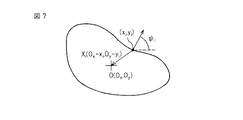
具体例として、図7に示されるような輪郭線形状の物体の像を入力画像の中から検出する場合について説明する。ここでは、説明を簡単にするために、比較的単純な形状の物体を例示しているが、より複雑な形状の物体であっても同様の手順で処理を行えばよい。 As a specific example, a case will be described in which an image of an object having an outline shape as shown in FIG. 7 is detected from an input image. Here, in order to simplify the description, an object having a relatively simple shape is illustrated, but even an object having a more complicated shape may be processed in the same procedure.
まず、検出対象物の特徴量を抽出するために、図7に示されているような輪郭線形状の物体の像を含んだテンプレート画像の前処理を行なう。例えば、テンプレート画像にSobelフィルタをかけてエッジ画像へ変換する。次に、エッジ画像中から予め定められた閾値以上の強度を持つ画素を抽出し(一般にエッジ点と呼称される)、抽出したimax個のエッジ点の位置及び濃淡勾配方向を求める。Sobelフィルタを使用してエッジ点を求める方法は、「画像ハンドブック」(昭晃堂、1987年第一版)の第280〜286頁の「エッジと線の検出」などに記載されているように、一般的な技術であるので、ここでは詳しく説明しない。 First, in order to extract the feature amount of the detection target object, preprocessing of a template image including an image of an object having a contour shape as shown in FIG. 7 is performed. For example, the template image is converted to an edge image by applying a Sobel filter. Next, pixels having an intensity equal to or higher than a predetermined threshold are extracted from the edge image (generally referred to as edge points), and the positions and shade gradient directions of the extracted imax edge points are obtained. The method for obtaining the edge point using the Sobel filter is described in “Detection of Edges and Lines” on pages 280 to 286 of “Image Handbook” (Shojido, first edition of 1987). Since it is a general technique, it will not be described in detail here.
さらに、図7に示される輪郭線形状内の任意の点、例えば幾何学的形状の重心を基準点O(Ox,Oy)として設定し、imax個のエッジ点の各々の位置及び濃淡勾配方向の情報から、各エッジ点(xi,yi)から基準点O(Ox,Oy)へ向かうベクトルXi(Vxi,Vyi)と各エッジ点(xi,yi)における濃度勾配方向ψiとを求め、特徴量(Vxi,Vyi,ψi)の集合体として検出対象物の特徴量モデルを定義する。この特徴モデルは、検出対象物の像の幾何学的特徴を数値によって表したものと言える。具体的には、図8に示されているように、濃度勾配方向ψiごとにベクトルXiの座標値(Vxi,Vyi)を登録した「Rテーブル」を作成し、これを特徴量モデルとする。ここで、Vxi=Ox−xi、Vyi=Oy−yiである。「Rテーブル」を作成することにより、入力画像から抽出したエッジ点の特徴量が検出対象物の特徴量モデルを構成する特徴量の一つに対応すると仮定したときの入力画像中における基準点Oの位置を求めることができるようになる。 Furthermore, an arbitrary point in the contour line shape shown in FIG. 7, for example, the centroid of the geometric shape is set as a reference point O (O x , O y ), and the position and gray scale of each of the imax edge points are set. From the direction information, the vector X i (Vx i , Vy i ) from each edge point (x i , y i ) to the reference point O (O x , O y ) and each edge point (x i , y i ) A density gradient direction ψ i is obtained, and a feature amount model of the detection target is defined as an aggregate of feature amounts (Vx i , Vy i , ψ i ). It can be said that this feature model is a numerical representation of the geometric feature of the image of the detection object. Specifically, as shown in FIG. 8, an “R table” in which the coordinate values (Vx i , Vy i ) of the vector X i are registered for each density gradient direction ψ i is created, and this is used as a feature quantity. Model. Here, Vx i = O x -x i , a Vy i = O y -y i. By creating the “R table”, the reference point O in the input image when it is assumed that the feature quantity of the edge point extracted from the input image corresponds to one of the feature quantities constituting the feature quantity model of the detection target object. The position of can be obtained.
次に、同様に入力画像の前処理を行って入力画像中の物体の像の特徴量を抽出し、各特徴量についてパラメータ空間内のセルへの投票を行う。入力画像に写った検出対象物の像の大きさが変わらない場合を例にとると、パラメータ空間は(u,v,θ)の3次元で定義される。投票は、入力画像中の全てのエッジ点の特徴量(xj,yj,ψj)の濃淡勾配方向ψjに対して、特徴量モデルの各特徴量(Vxi,Vyi,ψi)の濃淡勾配方向ψiをθ=ψj-ψiだけ回転させて濃淡勾配方向を一致させたときに特徴量モデルの基準点Oが示す位置(u,v)を求め、該当する3次元パラメータ空間上の点(u,v,θ)のセルの投票度数を1増やすというやり方で行なわれる。特徴量モデルの各特徴量を(Vxi,Vyi,ψi)(ただし、i=1,…,N)とし、入力画像中のエッジ点の特徴量を(xj,yj,ψj)(ただし、j=1,…,M)としたとき、次の式で入力画像中の各エッジ点の特徴量に対するパラメータ空間上の点(u,v,θ)が求まる。ここで、R(θ)は回転行列を意味する。
θ=ψj−ψi
Vxi=Ox−xi,Vyi=Oy−yi
[u v]T=R(θ)[Vxi Vyi]T+[xj yj]T (5)
Next, preprocessing of the input image is performed in the same manner to extract the feature quantity of the object image in the input image, and each feature quantity is voted on a cell in the parameter space. Taking the case where the size of the image of the detection object shown in the input image does not change as an example, the parameter space is defined in three dimensions (u, v, θ). Voting is performed for each feature amount (Vx i , Vy i , ψ i ) of the feature amount model with respect to the gradient gradient direction ψ j of the feature amounts (x j , y j , ψ j ) of all edge points in the input image. ), The position (u, v) indicated by the reference point O of the feature quantity model is obtained by rotating the shade gradient direction ψ i by θ = ψ j -ψ i to match the shade gradient direction, and the corresponding three-dimensional This is done by increasing the vote count of the cell at the point (u, v, θ) on the parameter space by one. Each feature quantity of the feature quantity model is (Vx i , Vy i , ψ i ) (where i = 1,..., N), and feature quantities of edge points in the input image are (x j , y j , ψ j ) (Where j = 1,..., M), the point (u, v, θ) on the parameter space for the feature quantity of each edge point in the input image is obtained by the following equation. Here, R (θ) means a rotation matrix.
θ = ψ j −ψ i
Vx i = O x -x i, Vy i = O y -y i
[U v] T = R (θ) [Vx i Vy i ] T + [x j y j ] T (5)
検出する対象物の大きさsを考慮した場合には、パラメータ空間が(u,v,θ,s)の4次元空間となるが、上述した式(5)のベクトル(Vxi,Vyi)に大きさの係数sを乗算した式で(u,v)を求めればよく、基本的な考え方は同じである。 When the size s of the object to be detected is taken into consideration, the parameter space is a four-dimensional space of (u, v, θ, s), but the vector (Vx i , Vy i ) in the above equation (5). (U, v) may be obtained by an expression obtained by multiplying the coefficient s by the magnitude s, and the basic idea is the same.
入力画像中の全てのエッジ点の特徴量に対するパラメータ空間への投票が終了したとき、パラメータ空間の各セルのうち投票度数の高いセルが(u0,v0,θ0)であったとすると、入力画像中の(u0,v0)の位置に姿勢θ0で特徴量モデルによって表わされる検出対象物の像が映っていると推測されることになる。投票度数を特徴量モデルの総特徴量数で除算したもの(以下、スコアSと称する)が、正規化された相互相関係数に相当する数値、すなわち入力画像中の物体の像と特徴量モデルに定義される検出対象物の像との相関度を表す数値であり、このスコアSが予め定められた閾値以上であれば、特徴量モデルによって表される検出対象物の像がスコアSを持つセルに対応するポーズで入力画像中に検出されたと判断され、このスコアSが予め定められた閾値より小さければ、検出対象物の像が入力画像中に検出されなかったと判断される。スコアSは0から1までの値をとり、これに対して閾値も0から1までの適宜の値に設定しうる。この閾値を余り高く設定しすぎると、入力画像中のノイズ等で検出ができなくなる可能性があり、反対に低く設定しすぎると誤検出を招く可能性がある。したがって、条件にもよるが、概ね0.7ぐらいが適している。 When voting to the parameter space with respect to the feature values of all edge points in the input image is completed, if the cells having a high voting frequency among the cells in the parameter space are (u 0 , v 0 , θ 0 ), It is estimated that an image of the detection target represented by the feature amount model with the posture θ 0 is reflected at the position (u 0 , v 0 ) in the input image. A value obtained by dividing the voting frequency by the total feature quantity of the feature quantity model (hereinafter referred to as score S) is a numerical value corresponding to the normalized cross-correlation coefficient, that is, the image of the object in the input image and the feature quantity model. If the score S is greater than or equal to a predetermined threshold value, the image of the detection object represented by the feature amount model has a score S. If it is determined that the pose corresponding to the cell is detected in the input image, and the score S is smaller than a predetermined threshold value, it is determined that the image of the detection target is not detected in the input image. The score S takes a value from 0 to 1, while the threshold value can be set to an appropriate value from 0 to 1. If this threshold value is set too high, detection may not be possible due to noise or the like in the input image, while if it is set too low, erroneous detection may occur. Therefore, about 0.7 is suitable although it depends on conditions.
次に、検出対象物の像が入力画像中に検出されたと判断されると、特徴量モデルのどの特徴量が検出に寄与したかを評価し、特徴量モデルの各特徴量の貢献指数Pを求める。このために、まず特徴量モデルの各特徴量に対応するメモリ領域を用意し、ある時点で特徴量に対応するメモリの値を0にクリアし、検出対象物の像が入力画像中に検出されるたびに、特徴量モデルの各特徴量についてその特徴量がその検出に寄与したかを評価し、寄与している場合はメモリに貢献度値Ctとして所定の定数(例えば1)を加算していけばよい。貢献指数Pは、メモリの値そのものとしてもよいし、別途加算回数を数えておき、メモリに保存された値を加算回数で除算した、いわゆる平均値としてもよい。 Next, when it is determined that an image of the detection target is detected in the input image, it is evaluated which feature quantity of the feature quantity model contributes to the detection, and a contribution index P of each feature quantity of the feature quantity model is determined. Ask. For this purpose, first, a memory area corresponding to each feature quantity of the feature quantity model is prepared, and the value of the memory corresponding to the feature quantity is cleared to 0 at a certain time, and the image of the detection target is detected in the input image. Each time, each feature quantity of the feature quantity model is evaluated as to whether or not the feature quantity contributed to the detection. If it contributes, a predetermined constant (for example, 1) is added to the memory as a contribution value Ct. I'll do it. The contribution index P may be a memory value itself, or may be a so-called average value obtained by separately counting the number of additions and dividing the value stored in the memory by the number of additions.
特徴量モデルのある特徴量(Vxi,Vyi,ψi)が、あるポーズ(u,v,θ)の投票に寄与したかどうかは以下のようにして評価することができる。すなわち、上述した式(5)に(Vxi,Vyi,ψi)と(u,v,θ)を代入し、逆算して(xj,yj,ψj)を求める。求めた(xj,yj,ψj)に一致する特徴量がエッジ点として入力画像中にあれば検出に寄与していると判断することが出来る。 Whether a certain feature amount (Vx i , Vy i , ψ i ) of the feature amount model contributes to voting for a certain pose (u, v, θ) can be evaluated as follows. That is, (Vx i , Vy i , ψ i ) and (u, v, θ) are substituted into the above-described equation (5), and (x j , y j , ψ j ) is obtained by back calculation. It can be determined that if the feature quantity matching the obtained (x j , y j , ψ j ) is an edge point in the input image, it contributes to detection.
特徴量モデルの各特徴量(Vxi,Vyi,ψi)の貢献指数Pは、検出対象物の複数回の検出に関する貢献度値が加算されたものであるので統計的な意味を有しており、値が大きいほど、対応する特徴量モデルの特徴量が検出対象物の像の検出に貢献する度合いが高いことを意味し、逆に値が小さいほど、対応する特徴量が検出対象物の像の検出に貢献する度合いが低いことを意味する。例えば図9に示されているような図形を検出対象物の輪郭線形状とした場合、図10に示されているように、小さい方の円の半径が図9の円2(図10では点線で示されている)よりも少し大きい円2’のようであったとすると、円2に対応する特徴量の貢献度が特徴量モデルに含まれる他の特徴量の貢献度よりも小さくなる。
The contribution index P of each feature quantity (Vx i , Vy i , ψ i ) of the feature quantity model has a statistical meaning because it contributes the contribution values related to multiple detections of the detection target. The larger the value, the higher the degree to which the feature quantity of the corresponding feature quantity model contributes to the detection of the image of the detection object. Conversely, the smaller the value, the more the corresponding feature quantity is the detection object. This means that the degree of contribution to image detection is low. For example, when the figure as shown in FIG. 9 is used as the outline shape of the detection object, the radius of the smaller circle is
そして、図11に例示されるような、ある時点での貢献指数Pに対して適宜の閾値Thが設定され、特徴量モデルのある特徴量に対応する貢献指数Pが閾値Thより小さい場合に、その特徴量は検出対象物の像の検出に対する貢献の度合いが低いと判断されて、特徴量モデルの中から除外され、スコアSの演算においても演算対象から除外される。こうして特徴量モデルの自動修正が行われることになる。 Then, as illustrated in FIG. 11, when an appropriate threshold value Th is set for the contribution index P at a certain point in time, and the contribution index P corresponding to a certain feature quantity in the feature quantity model is smaller than the threshold Th, The feature amount is determined to have a low degree of contribution to the detection of the image of the detection target, is excluded from the feature amount model, and is also excluded from the calculation target in the calculation of the score S. In this way, the feature amount model is automatically corrected.
以上、正規化された相互相関係数を用いた検出対象物の検出及び幾何学的特徴を用いた検出対象物の検出を例に、本発明の画像処理装置10における特徴量モデルの自動修正の手順について説明したが、本発明の画像処理装置10は、正規化された相互相関係数Cを用いた検出対象物の検出及び幾何学的特徴を用いた検出対象物の検出を行うものに限定されるものではなく、特徴量モデルと入力画像とのマッチングに相関度を用いるタイプのマッチング処理を行うものであれば、任意のタイプの画像処理装置に適用可能である。また、上記実施形態では、貢献指数Pの求め方を例示しているが、貢献指数Pの求め方は、例示される方法に限定されるものではなく、適宜に定めることが可能である。
As described above, the detection of the detection target using the normalized cross-correlation coefficient and the detection of the detection target using the geometric feature are examples of automatic correction of the feature amount model in the
10 画像処理装置
35 マッチング処理手段
36 特徴量貢献度算出手段
38 特徴量貢献度加算手段
40 特徴量モデル修正手段
42 特徴量モデル記憶手段
44 特徴量貢献指数記憶手段
DESCRIPTION OF
Claims (4)
前記相関度を求めるための相関度算出処理を行うマッチング処理手段と、
前記相関度算出処理を行った後、前記特徴量モデルの前記複数の特徴量の各々について、直前の相関度算出処理における前記相関度の増加への貢献度を算出し、算出された貢献度を累積した値に基づいて貢献指数を求める特徴量貢献指数算出手段と、
複数の異なる入力画像に対して、前記特徴量モデルの前記複数の特徴量の各々についての前記貢献度を算出し、該貢献度を累積した値に基づいた前記貢献指数を求めた後、前記特徴量モデルの前記複数の特徴量の各々について、求められた該貢献指数が予め定められた閾値以下であるか否か判定し、該貢献指数が予め定められた閾値以下であった場合に、該特徴量を前記特徴量モデルの前記複数の特徴量から除外することにより、前記特徴量モデルを修正する特徴量モデル修正手段と、を備えることを特徴とする画像処理装置。 An image of the detection target is detected from the input image based on a degree of correlation between a feature amount model of the detection target defined in advance using a plurality of feature amounts and the input image acquired by the imaging device. An image processing apparatus,
Matching processing means for performing correlation degree calculation processing for obtaining the correlation degree;
After performing the correlation degree calculation process, for each of the plurality of feature quantities of the feature quantity model, calculate a contribution degree to the increase in the correlation degree in the immediately preceding correlation degree calculation process, and calculate the calculated contribution degree A feature value contribution index calculating means for calculating a contribution index based on the accumulated value;
After calculating the contribution degree for each of the plurality of feature amounts of the feature amount model for a plurality of different input images, and determining the contribution index based on a value obtained by accumulating the contribution degrees, the feature For each of the plurality of feature quantities of the quantity model, it is determined whether or not the calculated contribution index is equal to or less than a predetermined threshold, and when the contribution index is equal to or less than a predetermined threshold, An image processing apparatus comprising: a feature amount model correcting unit that corrects the feature amount model by excluding the feature amount from the plurality of feature amounts of the feature amount model .
Priority Applications (1)
| Application Number | Priority Date | Filing Date | Title |
|---|---|---|---|
| JP2008266567A JP5080416B2 (en) | 2008-10-15 | 2008-10-15 | Image processing apparatus for detecting an image of a detection object from an input image |
Applications Claiming Priority (1)
| Application Number | Priority Date | Filing Date | Title |
|---|---|---|---|
| JP2008266567A JP5080416B2 (en) | 2008-10-15 | 2008-10-15 | Image processing apparatus for detecting an image of a detection object from an input image |
Publications (2)
| Publication Number | Publication Date |
|---|---|
| JP2010097341A JP2010097341A (en) | 2010-04-30 |
| JP5080416B2 true JP5080416B2 (en) | 2012-11-21 |
Family
ID=42258988
Family Applications (1)
| Application Number | Title | Priority Date | Filing Date |
|---|---|---|---|
| JP2008266567A Active JP5080416B2 (en) | 2008-10-15 | 2008-10-15 | Image processing apparatus for detecting an image of a detection object from an input image |
Country Status (1)
| Country | Link |
|---|---|
| JP (1) | JP5080416B2 (en) |
Cited By (1)
| Publication number | Priority date | Publication date | Assignee | Title |
|---|---|---|---|---|
| US11227144B2 (en) | 2015-11-06 | 2022-01-18 | Fanuc Corporation | Image processing device and method for detecting image of object to be detected from input data |
Families Citing this family (3)
| Publication number | Priority date | Publication date | Assignee | Title |
|---|---|---|---|---|
| JP6075888B2 (en) * | 2014-10-16 | 2017-02-08 | キヤノン株式会社 | Image processing method, robot control method |
| EP3404583A1 (en) | 2017-05-19 | 2018-11-21 | MVTec Software GmbH | System and method for model adaptation |
| JP6824859B2 (en) * | 2017-10-13 | 2021-02-03 | 三菱重工業株式会社 | In-core state quantity estimation device, estimation model creation device, their programs and methods |
Family Cites Families (1)
| Publication number | Priority date | Publication date | Assignee | Title |
|---|---|---|---|---|
| JP3484905B2 (en) * | 1996-11-26 | 2004-01-06 | オムロン株式会社 | State determination device |
-
2008
- 2008-10-15 JP JP2008266567A patent/JP5080416B2/en active Active
Cited By (1)
| Publication number | Priority date | Publication date | Assignee | Title |
|---|---|---|---|---|
| US11227144B2 (en) | 2015-11-06 | 2022-01-18 | Fanuc Corporation | Image processing device and method for detecting image of object to be detected from input data |
Also Published As
| Publication number | Publication date |
|---|---|
| JP2010097341A (en) | 2010-04-30 |
Similar Documents
| Publication | Publication Date | Title |
|---|---|---|
| CN109389135B (en) | Image screening method and device | |
| CN110919653B (en) | Stair climbing control method and device for robot, storage medium and robot | |
| US7577297B2 (en) | Pattern identification method, device thereof, and program thereof | |
| US20070189584A1 (en) | Specific expression face detection method, and imaging control method, apparatus and program | |
| CN105740780B (en) | Method and device for detecting living human face | |
| US8577099B2 (en) | Method, apparatus, and program for detecting facial characteristic points | |
| US9007481B2 (en) | Information processing device and method for recognition of target objects within an image | |
| US20110075933A1 (en) | Method for determining frontal face pose | |
| KR102073468B1 (en) | System and method for scoring color candidate poses against a color image in a vision system | |
| CN101983507A (en) | Automatic redeye detection | |
| CN111553310B (en) | Security inspection image acquisition method and system based on millimeter wave radar and security inspection equipment | |
| CN112381061B (en) | Facial expression recognition method and system | |
| CN113962306A (en) | Image processing method, image processing device, electronic equipment and computer readable storage medium | |
| JP5080416B2 (en) | Image processing apparatus for detecting an image of a detection object from an input image | |
| CN112884782A (en) | Biological object segmentation method, apparatus, computer device and storage medium | |
| JP2011165170A (en) | Object detection device and program | |
| CN109034058B (en) | Method and system for dividing and self-correcting region in image | |
| CN113252103A (en) | Method for calculating volume and mass of material pile based on MATLAB image recognition technology | |
| JP4690190B2 (en) | Image processing method, apparatus, and program | |
| CN113658274B (en) | Automatic individual spacing calculation method for primate population behavior analysis | |
| JP2007080136A (en) | Specification of object represented within image | |
| CN112686851B (en) | Image detection method, device and storage medium | |
| JP4298283B2 (en) | Pattern recognition apparatus, pattern recognition method, and program | |
| CN111563883B (en) | Screen vision positioning method, positioning equipment and storage medium | |
| CN107909610A (en) | A kind of gray scale target perimeter evaluation method based on image grain and sub-pix border detection |
Legal Events
| Date | Code | Title | Description |
|---|---|---|---|
| A621 | Written request for application examination |
Free format text: JAPANESE INTERMEDIATE CODE: A621 Effective date: 20110523 |
|
| A977 | Report on retrieval |
Free format text: JAPANESE INTERMEDIATE CODE: A971007 Effective date: 20120511 |
|
| A131 | Notification of reasons for refusal |
Free format text: JAPANESE INTERMEDIATE CODE: A131 Effective date: 20120522 |
|
| A521 | Written amendment |
Free format text: JAPANESE INTERMEDIATE CODE: A523 Effective date: 20120719 |
|
| TRDD | Decision of grant or rejection written | ||
| A01 | Written decision to grant a patent or to grant a registration (utility model) |
Free format text: JAPANESE INTERMEDIATE CODE: A01 Effective date: 20120807 |
|
| A01 | Written decision to grant a patent or to grant a registration (utility model) |
Free format text: JAPANESE INTERMEDIATE CODE: A01 |
|
| A61 | First payment of annual fees (during grant procedure) |
Free format text: JAPANESE INTERMEDIATE CODE: A61 Effective date: 20120830 |
|
| FPAY | Renewal fee payment (event date is renewal date of database) |
Free format text: PAYMENT UNTIL: 20150907 Year of fee payment: 3 |
|
| R150 | Certificate of patent or registration of utility model |
Ref document number: 5080416 Country of ref document: JP Free format text: JAPANESE INTERMEDIATE CODE: R150 Free format text: JAPANESE INTERMEDIATE CODE: R150 |