JP5079720B2 - Underwater imaging device - Google Patents
Underwater imaging device Download PDFInfo
- Publication number
- JP5079720B2 JP5079720B2 JP2009036743A JP2009036743A JP5079720B2 JP 5079720 B2 JP5079720 B2 JP 5079720B2 JP 2009036743 A JP2009036743 A JP 2009036743A JP 2009036743 A JP2009036743 A JP 2009036743A JP 5079720 B2 JP5079720 B2 JP 5079720B2
- Authority
- JP
- Japan
- Prior art keywords
- data
- moving image
- image data
- storage
- shooting
- Prior art date
- Legal status (The legal status is an assumption and is not a legal conclusion. Google has not performed a legal analysis and makes no representation as to the accuracy of the status listed.)
- Expired - Fee Related
Links
Images


Classifications
-
- A—HUMAN NECESSITIES
- A01—AGRICULTURE; FORESTRY; ANIMAL HUSBANDRY; HUNTING; TRAPPING; FISHING
- A01K—ANIMAL HUSBANDRY; CARE OF BIRDS, FISHES, INSECTS; FISHING; REARING OR BREEDING ANIMALS, NOT OTHERWISE PROVIDED FOR; NEW BREEDS OF ANIMALS
- A01K97/00—Accessories for angling
Description
本発明は、水中の様子や水中に生息する魚等の水生生物を撮像するための水中撮像装置に関する。 The present invention relates to an underwater imaging device for imaging aquatic organisms such as underwater conditions and fish that live in the water.
近年、アウトドアレジャーがブームとなっており、その中でも魚釣りは年齢を問わず高い人気を集めている。この魚釣りにおいて、水中の様子や釣り上げる魚等を撮像するための水中撮像装置が利用に供されている(例えば、特許文献1参照)。この水中撮像装置は、釣り具と、釣り具に搭載されたデジタルカメラ及びリモコンボックスと、を備えている。 In recent years, outdoor leisure has become a boom, and fishing is gaining popularity regardless of age. In this fishing, an underwater imaging device for imaging an underwater state, a fish to be fished, and the like is used (for example, see Patent Document 1). This underwater imaging device includes a fishing tackle, a digital camera and a remote control box mounted on the fishing tackle.
釣り具は、釣り竿と、釣り竿に支持されたリールと、リールに巻き取り及び送り出し自在に巻回された釣り糸と、を備えている。釣り糸は光ファイバから構成され、デジタルカメラ及びリモコンボックスが釣り糸によって相互に接続されている。デジタルカメラには、鉤素を介して釣り針が取り付けられ、この釣り針には餌が取り付けられている。また、リモコンボックスは釣り竿に取り付けられ、このリモコンボックスには、デジタルカメラにより撮像された動画を表示するための液晶モニタと、デジタルカメラのシャッタボタンを遠隔操作するための操作スイッチとが設けられている。 The fishing tackle includes a fishing rod, a reel supported by the fishing rod, and a fishing line wound around the reel so as to be wound and fed out. The fishing line is composed of an optical fiber, and the digital camera and the remote control box are connected to each other by the fishing line. A digital camera is attached with a fishhook through silicon, and a bait is attached to the fishhook. The remote control box is attached to a fishing rod, and the remote control box is provided with a liquid crystal monitor for displaying a moving image captured by the digital camera and an operation switch for remotely operating the shutter button of the digital camera. Yes.
上述した水中撮像装置は、次のようにして使用される。釣り竿は水上又は地上の釣り人によって把持され、デジタルカメラは水中に沈められる。デジタルカメラからの撮像データは釣り糸(光ファイバ)を介してリモコンボックスに伝送され、これによりデジタルカメラにより撮像された動画が液晶モニタに表示される。釣り人は、液晶モニタに表示された水中の様子を見ながら、例えば魚等が餌に食い付く瞬間のシャッタチャンスが到来するのを待つ。シャッタチャンスが到来すると、操作スイッチを押圧操作することにより、デジタルカメラのシャッタボタンが遠隔操作され、魚等が餌に食い付く瞬間の動画を撮影することができる。 The underwater imaging device described above is used as follows. The fishing rod is grasped by a fisherman on the water or on the ground, and the digital camera is submerged in water. Imaging data from the digital camera is transmitted to the remote control box via fishing line (optical fiber), whereby a moving image captured by the digital camera is displayed on the liquid crystal monitor. The angler waits for a photo opportunity at the moment when, for example, a fish or the like bites into the bait while watching the underwater state displayed on the liquid crystal monitor. When a photo opportunity arrives, the shutter button of the digital camera is remotely operated by pressing the operation switch, and a moving image at the moment when the fish or the like bites into the bait can be taken.
しかしながら、上述のような従来の水中撮像装置では、シャッタチャンスが何の前触れもなく突然到来した場合には、操作スイッチを押圧操作するタイミングが遅れることがあり、シャッタチャンスを捕らえることが難しいという問題がある。 However, in the conventional underwater imaging device as described above, when the shutter chance suddenly arrives without any previous notice, the timing of pressing the operation switch may be delayed, and it is difficult to capture the shutter chance. There is.
本発明の目的は、シャッタチャンスを確実に捕らえることができる水中撮像装置を提供することである。 An object of the present invention is to provide an underwater imaging device capable of reliably capturing a photo opportunity.
本発明の請求項1に記載の水中撮像装置は、水中の被写体を撮像するための光学レンズ及び撮像素子を有する撮像手段と、前記撮像手段からの撮像データに基づいて動画データを生成して保存記憶する動画データ生成手段と、前記撮像手段からの前記撮像データを前記動画データ生成手段に伝送するための通信手段と、動画撮影の開始を指示する撮影開始指示手段と、を備え、
前記動画データ生成手段は、前記撮像手段からの前記撮像データをモーションJPEG方式で圧縮するためのデータ圧縮手段と、前記データ圧縮手段により圧縮して得られる画像データを一時的に記憶するための第1記憶手段と、前記画像データに対応する画像サイズデータを一時的に記憶するための第2記憶手段と、前記画像データに対応するアドレスデータを一時的に記憶するための第3記憶手段と、前記第1〜第3記憶手段にそれぞれ一時的に記憶された前記各データに基づいて生成された動画データを保存記憶するための保存記憶手段と、前記第1〜第3記憶手段への前記各データの一時的記憶及び前記保存記憶手段への前記動画データの保存記憶を制御するための制御手段と、を有し、
前記制御手段は、前記データ圧縮手段により圧縮して得られる前記画像データを複数フレーム分に渡って前記第1記憶手段に記憶させるとともに、前記画像データに対応する前記画像サイズデータ及び前記アドレスデータをそれぞれ前記第2及び第3記憶手段に複数フレーム分に渡って記憶させ、その後、前記第1〜第3記憶手段にそれぞれ記憶された最も古い前記各データを順次消去させるとともに、最も新しい前記各データを前記第1〜第3記憶手段にそれぞれ順次記憶させ、
前記撮影開始指示手段により動画撮影の開始が指示されると、前記制御手段は、撮影開始の指示時において前記第1〜第3記憶手段にそれぞれ記憶されている前記各データ及び撮影開始の指示後に前記第1〜第3記憶手段にそれぞれ記憶される前記各データに基づいて前記動画データを生成し、この生成された前記動画データを前記保存記憶手段に記憶させることを特徴とする。
An underwater imaging apparatus according to claim 1 of the present invention generates an image data having an optical lens and an image sensor for imaging an underwater subject, and generates and saves moving image data based on the image data from the imaging means. Moving image data generating means for storing, communication means for transmitting the imaging data from the imaging means to the moving image data generating means, and shooting start instruction means for instructing start of moving image shooting ,
The moving image data generation means includes a data compression means for compressing the image pickup data from the image pickup means by a motion JPEG method, and a first data for temporarily storing image data obtained by compression by the data compression means. 1 storage means, second storage means for temporarily storing image size data corresponding to the image data, third storage means for temporarily storing address data corresponding to the image data, A storage unit for storing and storing moving image data generated based on the data temporarily stored in the first to third storage units, and the first to third storage units. Control means for controlling temporary storage of data and storage storage of the moving image data in the storage storage means,
The control means stores the image data obtained by compression by the data compression means in the first storage means for a plurality of frames, and stores the image size data and the address data corresponding to the image data. Each of the second and third storage means stores the data for a plurality of frames, and then the oldest data stored in the first to third storage means are sequentially deleted, and the newest data Are sequentially stored in the first to third storage means,
When the start of moving image shooting is instructed by the shooting start instructing unit, the control unit, after instructing to start shooting, after each of the data stored in the first to third storage units and the instruction to start shooting The moving image data is generated based on the data stored in the first to third storage units, and the generated moving image data is stored in the storage unit.
また、本発明の請求項2に記載の水中撮像装置では、前記動画データは、ヘッダ部、データ部及びフッタ部から構成され、
前記撮影開始指示手段により動画撮影の開始が指示されると、前記制御手段は、前記第3記憶手段に記憶された前記アドレスデータを読み出し、更にこのアドレスデータに対応する前記第1及び第2記憶手段にそれぞれ記憶された前記画像データ及び前記画像サイズデータを読み出し、読み出した前記画像データに基づいて前記データ部を作成し、読み出した前記画像サイズデータ及び前記アドレスデータに基づいて前記ヘッダ部及び前記フッタ部を作成することを特徴とする。
In the underwater imaging device according to
When the start of moving image shooting is instructed by the shooting start instruction means, the control means reads the address data stored in the third storage means, and further, the first and second memories corresponding to the address data Read the image data and the image size data respectively stored in the means, create the data portion based on the read image data, and based on the read image size data and the address data, the header portion and the A footer part is created.
また、本発明の請求項3に記載の水中撮像装置では、前記通信手段は、釣り竿に支持されたリール手段に巻き取り及び送り出し自在に巻回される釣り糸から構成され、前記釣り糸の一端部は、前記釣り竿から延びて前記撮像手段の上端部に接続され、その他端部は前記動画データ生成手段に接続され、前記撮像装置の下端部には前記光学レンズ及び前記撮像素子が配設され、また、前記撮影開始指示手段は、前記釣り竿に設けられて魚信を検知するための魚信検知センサから構成され、前記魚信検知センサが魚信を検知すると、動画撮影が開始されることを特徴とする。
Moreover, in the underwater imaging device according to
また、本発明の請求項4に記載の水中撮像装置では、前記動画データに基づく動画を表示するための表示手段を更に備え、前記表示手段は、前記リール手段に着脱自在に取り付けられるとともに、前記動画データ生成手段と有線又は無線で通信接続されることを特徴とする。 The underwater imaging device according to claim 4 of the present invention further includes display means for displaying a moving image based on the moving image data, the display means being detachably attached to the reel means, The moving image data generating means is connected by wire or wireless communication.
本発明の請求項1に記載の水中撮像装置によれば、撮影開始指示手段による動画撮影の開始の指示の前後に渡る一定時間の動画を撮影することができるので、例えば水中の魚等が撮像手段の前方に仕掛けた餌に突然食い付くなど、シャッタチャンスが何の前触れもなく突然到来した場合であっても、シャッタチャンスを確実に捕らえることができる。また、1フレーム毎に画像データ、画像サイズデータ及びアドレスデータに分離して管理することによって、動画データ生成手段の構成を簡単なものとすることができる。これによって、撮像データをモーションJPEG形式により圧縮するタイプの水中撮像装置において、動画前後撮影機能を容易に搭載することができる。 According to the underwater imaging device of the first aspect of the present invention, it is possible to shoot a moving image for a predetermined time before and after the instruction to start moving image shooting by the shooting start instruction means. Even if the photo opportunity suddenly arrives without any precautions such as suddenly eating the bait placed in front of the means, the photo opportunity can be reliably captured. In addition, by separating and managing image data, image size data, and address data for each frame, the configuration of the moving image data generation unit can be simplified. Thereby, in the underwater imaging device of the type that compresses the imaging data in the motion JPEG format, it is possible to easily mount the moving image front-rear imaging function.
また、本発明の請求項2に記載の水中撮像装置によれば、第3記憶手段に記憶されたアドレスデータを読み出し、更にこのアドレスデータに対応する第1及び第2記憶手段にそれぞれ記憶された画像データ及び画像サイズデータを読み出すことによって、読み出した画像データに基づいてデータ部を作成することができ、また、読み出した画像サイズデータ及びアドレスデータに基づいてヘッダ部及びフッタ部を作成することができる。このように作成されたヘッダ部、データ部及びフッタ部に基づいて、動画データを容易に生成することができる。
According to the underwater imaging device described in
また、本発明の請求項3に記載の水中撮像装置によれば、魚信検知センサが魚信を検知すると動画撮影が開始されるので、例えば魚等が釣り針に取り付けられた餌に食い付いた瞬間に動画撮影を自動的に開始することができ、動画撮影に気をとらわれることなく魚釣りに集中することができる。
In addition, according to the underwater imaging device according to
また、本発明の請求項4に記載の水中撮像装置によれば、表示手段はリール手段に着脱自在に取り付けられるので、表示手段をリール手段から脱着することにより、釣り竿から離れた場所でも表示手段に表示された水中の様子などを観察することができる。 According to the underwater imaging device of the fourth aspect of the present invention, since the display means is detachably attached to the reel means, the display means can be removed from the fishing rod by removing the display means from the reel means. You can observe the underwater state displayed on the screen.
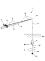
以下、添付図面を参照して、本発明に従う水中撮像装置の一実施形態について説明する。図1は、本発明の一実施形態による水中撮像装置を示す斜視図であり、図2は、図1のカメラ部を拡大して示す断面図であり、図3は、図1のリール部及びコントロールボックスを拡大して示す部分断面図であり、図4は、図1の水中撮像装置の制御系を示すブロック図であり、図5(a)は、動画データの構成を示す概念図であり、図5(b)は、動画データのヘッダ部の構成を示す概念図であり、図5(c)は、動画データのフッタ部の構成を示す概念図であり、図6(a)は、画像データが格納された第1記憶手段の構成を示す概念図であり、図6(b)は、画像サイズデータが格納された第2記憶手段の構成を示す概念図であり、図6(c)は、アドレスデータが格納された第3記憶手段の構成を示す概念図であり、図7は、撮像した画像と保存記憶手段に保存記憶される画像との関係を示すタイムチャートであり、図8は、動画前後撮影機能の制御の流れを説明するためのフローチャートである。 Hereinafter, an embodiment of an underwater imaging device according to the present invention will be described with reference to the accompanying drawings. FIG. 1 is a perspective view illustrating an underwater imaging device according to an embodiment of the present invention, FIG. 2 is an enlarged cross-sectional view illustrating a camera unit of FIG. 1, and FIG. FIG. 4 is a partial cross-sectional view showing an enlarged control box, FIG. 4 is a block diagram showing a control system of the underwater imaging device of FIG. 1, and FIG. 5 (a) is a conceptual diagram showing a configuration of moving image data. 5B is a conceptual diagram showing the configuration of the header portion of the moving image data, FIG. 5C is a conceptual diagram showing the configuration of the footer portion of the moving image data, and FIG. FIG. 6B is a conceptual diagram showing the configuration of the first storage means storing image data. FIG. 6B is a conceptual diagram showing the configuration of the second storage means storing image size data, and FIG. ) Is a conceptual diagram showing the configuration of the third storage means in which the address data is stored. FIG. A time chart showing a relationship between an image to be stored stored in the image and save the storage means, Figure 8 is a flowchart illustrating a flow of control of moving back and forth shooting function.
図1〜図3を参照して、図示の水中撮像装置2は、釣り具4と、釣り具4に搭載されたカメラ部6(撮像手段を構成する)及びコントロールボックス8と、を備えている。以下、水中撮像装置2の構成について詳細に説明する。
With reference to FIGS. 1 to 3, the illustrated
釣り具4は、釣り竿10、リール手段12及び釣り糸14を備えている。釣り竿10は伸縮自在に構成され、この釣り竿10には、釣り糸14をガイドするためのガイドリング16がその長手方向に間隔を置いて複数設けられている。釣り竿10の先端部に設けられたガイドリング16には、魚信を検知するための魚信検知センサ18(撮影開始指示手段を構成する)が内蔵されている。この魚信検知センサ18は、本実施形態では、釣り糸14に加わる振動や衝撃により電気信号を発生する圧電素子から構成されており、魚信検知センサ18からの電気信号は、コントロールボックス8に内蔵された動画データ生成手段68(後述する)に無線で伝送される。
The fishing gear 4 includes a
リール手段12は、釣り竿10の基端部に支持されたフレーム20と、フレーム20に回転自在に支持された回転ドラム22と、回転ドラム22に駆動伝達ギヤ(図示せず)を介して駆動連結された操作ハンドル24とから構成されている(図3参照)。回転ドラム22には、釣り糸14の他端部を挿通するための挿通孔26が設けられている。
The reel means 12 is connected to a
釣り糸14(通信手段を構成する)は直径約1.5mm程度の電気通信ケーブルから構成され、回転ドラム22に巻き取り及び送り出し自在に巻回されている。操作ハンドル24を図3中の矢印Pで示す方向に回転操作すると、回転ドラム22が巻き取り方向に回転され、釣り糸14が回転ドラム22に巻き取られる。また、操作ハンドル24を図3中の矢印Qで示す方向に回転操作すると、回転ドラム22が送り出し方向に回転され、釣り糸14が回転ドラム22から送り出される。リール手段12から送り出された釣り糸14の一端部は、複数のガイドリング16を通して釣り竿10の長手方向に沿って延びた後に、釣り竿10の先端部から延びてカメラ部6の上端部に接続されている。また、釣り糸14の他端部は、回転ドラム22の挿通孔26を通して外部に延び、コントロールボックス8に内蔵された動画データ生成手段68に電気的に接続されている。
The fishing line 14 (which constitutes the communication means) is composed of an electric communication cable having a diameter of about 1.5 mm, and is wound around the
カメラ部6は、略円筒状のケーシング28と、ケーシング28に内蔵されたCCDカメラ30と、を備えている(図2参照)。ケーシング28の上端部は上壁部32によって閉塞され、この上壁部32には、釣り糸14の一端部を挿通するための貫通孔34が設けられている。ケーシング28の下端部は開口され、この下端部には、装着リング36を介して透明なガラス又は樹脂から形成された透光板38が装着されている。また、装着リング36には一対の係止フック40が設けられ、この一対の係止フック40には鉤素42が取り付けられている。この鉤素42は、一対の係止フック40から略V字状に延びる一対の第1鉤素部44と、一対の第1鉤素部44の接続部から下方に延びる第2鉤素部46とから構成されている。第2鉤素部46の長さ方向中間部には複数の釣り針48が取り付けられ、釣り針48には餌(図示せず)が取り付けられている。また、第2鉤素部46の先端部には錘50が取り付けられている。なお、装着リング36を比重の大きい金属から形成することによって、カメラ部6を水中に沈めた際に、カメラ部6は、透光板38が水底方向を向くようにその姿勢が保たれる。
The camera unit 6 includes a substantially
CCDカメラ30は、光学レンズ52及び撮像素子54を有している。光学レンズ52は、ケーシング28の内部における透光板38の上側にレンズホルダ56を介して装着されている。撮像素子54は、ケーシング28の内部における光学レンズ52の上側に配設され、光学レンズ52によって結像された被写体の像を電気信号に光電変換する。また、ケーシング28の内部にはプリント配線基板58が配設され、このプリント配線基板58には、撮像素子54からの電気信号を所要の通りに処理するための信号処理回路(図示せず)が実装されている。プリント配線基板58には、コネクタ60を介して釣り糸14の一端部が電気的に接続されている。また、ケーシング28の内部にはシリカゲルなどの乾燥剤62が配設されており、これにより、カメラ部6が水中に沈められて冷やされることによって、ケーシング28内の空気に含まれる水分が結露するのが防止される。
The
コントロールボックス8は、リール手段12のフレーム20に着脱自在に取り付けられている。コントロールボックス8には、液晶モニタ64(表示手段を構成する)及び複数の操作スイッチ66が設けられている。液晶モニタ64には、カメラ部6により撮像された動画が表示される。複数の操作スイッチ66は、動画撮影を終了するための撮影終了スイッチ66などから構成されている。また、コントロールボックス8には動画データ生成手段68が内蔵されており、この動画データ生成手段68は、A/D変換回路70、データ圧縮手段72、第1〜第4記憶手段74,76,78,80、保存記憶手段82及び制御手段84を備えている(図4参照)。以下、動画データ生成手段68の構成について詳細に説明する。
The
A/D変換回路70は、撮像素子54からの電気信号、即ち撮像データをA/D変換する。データ圧縮手段72は、A/D変換回路70によってA/D変換された撮像データをモーションJPEG(Joint Photographic coding Experts Group)形式で圧縮する。データ圧縮手段72により圧縮して得られる画像データは、固定データと、JPEG画像データと、JPEG画像データのサイズを示す画像サイズデータと、を含んでいる(図5(a)参照)。
The A / D conversion circuit 70 A / D converts an electrical signal from the
第1〜第3記憶手段74,76,78はそれぞれリングバッファメモリから構成されている(図6(a)〜(c)参照)。第1記憶手段74には、データ圧縮手段72により圧縮して得られる画像データが一時的に記憶される。第2記憶手段76には、第1記憶手段74に記憶された画像データに対応して、画像データに含まれる画像サイズデータのコピーデータが一時的に記憶される。第3記憶手段78には、第1記憶手段74に記憶された画像データに対応して、画像データのアドレスを示すアドレスデータが一時的に記憶される。
The first to third storage means 74, 76, 78 are each constituted by a ring buffer memory (see FIGS. 6A to 6C). The
第1〜第3記憶手段74,76,78の各メモリ領域86,88,90には、先頭アドレスから最終アドレスまで順にデータが格納され、これにより複数フレーム分(例えば、100フレーム分)のデータが各メモリ領域86,88,90に格納される。各メモリ領域86,88,90の最終アドレスまでデータが格納されると、先頭アドレスに格納された最も古いデータが消去されるとともに、最も新しいデータが先頭アドレスに格納される。以下同様にして、先頭から2番目のアドレスに格納された最も古いデータが消去されるとともに、最も新しいデータが先頭から2番目のアドレスに格納され、このようにして最も古いデータが最も新しいデータによって順次上書きされる。
In each of the
また、第4記憶手段80はバッファメモリから構成されている。この第4記憶手段80には、後述する動画データ92のフッタ部94が一時的に記憶される。
The fourth storage means 80 is composed of a buffer memory. The fourth storage means 80 temporarily stores a
保存記憶手段82は、コントロールボックス8に取り出し自在に内蔵された例えばSDカードなどから構成され、制御手段84によって生成された動画データ92が保存記憶される。保存記憶手段82に保存記憶される動画データ92は、ヘッダ部96、データ部98及びフッタ部94から構成される(図5参照)。ヘッダ部96は、固定データ、ファイルサイズデータ、ヘッダサイズデータ、フレーム数データ及びデータサイズなどから構成されている。データ部98は、複数の画像データから構成されている。また、フッタ部94は、固定データ、フッタサイズデータ、複数フレーム分のデータ(固定データ、アドレスデータ及び画像サイズデータ)などから構成されている。
The
制御手段84は、例えばマイクロコンピュータなどから構成され、第1〜第4記憶手段74,76,78,80への各データの一時的記憶及び保存記憶手段82への動画データ92の保存記憶を後述するようにして制御する。
The control means 84 is composed of, for example, a microcomputer and the like, and temporarily stores each data in the first to fourth storage means 74, 76, 78, 80 and saves the moving
本実施形態の水中撮像装置2には、動画撮影の開始時点の前後に渡る一定時間の動画データ92を保存記憶する動画前後撮影機能が搭載されている。以下、図7及び図8をも参照して、この動画前後撮影機能について説明しながら、水中撮像装置2の使用方法について説明する。なお、本実施形態では、動画撮影が開始される時点で第1〜第3記憶手段74,76,78に記憶されている2フレーム分の画像A,Bに対応する各データと、動画撮影が開始されてから撮影終了スイッチ66を押圧するまでの間に第1〜第3記憶手段74,76,78に記憶される画像C,D,Eに対応する各データとに基づいて、動画データ92を生成する場合について説明する。
The
地上又は水上の釣り人(図示せず)が釣り竿10を把持して、リール手段12から送り出された釣り糸14を海や川、池などの水中に向かって放り投げることによって、カメラ部6が水中に沈められる。カメラ部6は、透光板38が水底方向を向くようにその姿勢が保たれる。また、第2鉤素部46の先端部に錘50が取り付けられているので、水流が速い場合であっても、カメラ部6と鉤素42とが同じように流されるようになり、これにより釣り針48に取り付けられた餌を求めて集まってくる魚等(図示せず)をカメラ部6により撮像することができる。
A fisherman (not shown) on the ground or water grasps the
魚等が餌に食い付く瞬間のシャッタチャンスが到来するまでの間、カメラ部6が水中の被写体(例えば、餌を求めて集まってくる魚等)に向けられることによって、水中の被写体の画像A,Bがカメラ部6によって撮像される(ステップS1)。カメラ部6の撮像素子54からの撮像データは、信号処理回路によって所要の通りに処理された後に、釣り糸14を介してコントロールボックス8内の動画データ生成手段68に伝送される。そして、この撮像データは、A/D変換回路70によってA/D変換された後に、データ圧縮手段72によってモーションJPEG形式で圧縮される(ステップS2)。圧縮によって得られた画像データA,Bは、第1記憶手段74に順次記憶される。また、この画像データに含まれる画像サイズデータA,Bのコピーデータが第2記憶手段76に順次記憶され、この画像データA,Bのアドレスを示すアドレスデータA,Bが第3記憶手段78に順次記憶される(ステップS3)。
The camera unit 6 is directed toward an underwater subject (for example, a fish that collects in search of food) until a shutter chance at the moment when the fish or the like bites into the bait, so that an image A of the underwater subject is obtained. , B are imaged by the camera unit 6 (step S1). The imaging data from the
なお、液晶モニタ64には、カメラ部6により撮像された映像がリアルタイムで表示され、釣り人は、この液晶モニタ64を見ることによって水中の様子を観察することができる。また、コントロールボックス8をリール手段12のフレーム20から脱着することにより、釣り具4から少し離れた場所で液晶モニタ64を見ることができる。
Note that an image captured by the camera unit 6 is displayed on the liquid crystal monitor 64 in real time, and the angler can observe the underwater state by looking at the
シャッタチャンスが到来し、画像Cがカメラ部6により撮像された時点で魚等が餌に食い付くと、魚信検知センサ18が魚信を検知し、ステップS4からステップS5に進む。これにより、魚信検知センサ18からの電気信号が動画データ生成手段68に無線で伝送され、動画の撮影が開始される。制御手段84は、第3記憶手段78に記憶されている画像Aに対応するアドレスデータAを読み出し、このアドレスデータAに対応する画像データA及び画像サイズデータAをそれぞれ第1及び第2記憶手段74,76から読み出す(ステップS6)。読み出された画像データAは保存記憶手段82に記憶され(ステップS7)、動画データ92のデータ部98のメモリ領域100に格納される。また、読み出された画像サイズデータA及びアドレスデータAは第4記憶手段80に記憶され(ステップS8)、動画データ92のフッタ部94のメモリ領域102に格納される。
When a photo opportunity arrives and a fish or the like bites into the bait when the image C is imaged by the camera unit 6, the fish
撮影終了スイッチ66を押圧操作するまでの間、上述と同様の制御が行われる。即ち、制御手段84は、第3記憶手段78に記憶されている画像B〜Eに対応するアドレスデータB〜Eを順次読み出し、このアドレスデータB〜Eに対応する画像データB〜E及び画像サイズデータB〜Eをそれぞれ第1及び第2記憶手段74,76から順次読み出す。読み出された画像データB〜Eは保存記憶手段82に順次記憶され、動画データ92のデータ部98のメモリ領域100に順次格納される。また、読み出された画像サイズデータB〜E及びアドレスデータB〜Eは第4記憶手段80に順次記憶され、動画データ92のフッタ部94のメモリ領域102に順次格納される。
The same control as described above is performed until the photographing
画像Eがカメラ部6により撮像された時点で撮影終了スイッチ66を押圧操作すると(ステップS9)、画像A〜Eに対応するデータが全て読み出されているときには、ステップS10からステップS14に進み、動画の撮影が終了される。画像A〜Eに対応するデータが全て読み出されていないときには、ステップS10からステップS11に進み、上述したステップS6〜ステップS8と同様にステップS11〜ステップS13が行われた後に、動画の撮影が終了される(ステップS14)。
When the photographing
動画の撮影が終了されると、保存記憶手段82においては、画像データA〜Eがデータ部98のメモリ領域100に順次格納されることによってデータ部98が作成されるとともに、画像サイズデータA〜E及びアドレスデータA〜Eに基づいて各データがヘッダ部96のメモリ領域104に順次格納されることによってヘッダ部96が作成され、また、第4記憶手段80においては、画像サイズデータA〜E及びアドレスデータA〜Eがフッタ部94のメモリ領域102に順次格納されることによってフッタ部94が作成される(ステップS15)。制御手段84は、第4記憶手段80において作成されたフッタ部94を保存記憶手段82に送給し、これら作成されたヘッダ部96、データ部98及びフッタ部94に基づいて動画データ92を生成する(ステップS16)。このように生成された動画データ92は保存記憶手段82に保存記憶される(ステップS17)。
When the shooting of the moving image is completed, the
従って、本実施形態の水中撮像装置2では、魚等が餌に食い付く瞬間の前後に渡る一定時間の動画を撮影することができるので、シャッタチャンスを確実に捕らえることができる。また、1フレーム毎に画像データ、画像サイズデータ及びアドレスデータに分離して管理することによって、動画データ生成手段68の構成を簡単なものとすることができる。これによって、撮像データをモーションJPEG形式により圧縮するタイプの水中撮像装置2において、動画前後撮影機能を容易に搭載することができる。
Therefore, in the
以上、本発明に従う水中撮像装置の一実施形態について説明したが、本発明はかかる実施形態に限定されるものではなく、本発明の範囲を逸脱することなく種々の変形乃至修正が可能である。 As mentioned above, although one embodiment of the underwater imaging device according to the present invention has been described, the present invention is not limited to such an embodiment, and various changes or modifications can be made without departing from the scope of the present invention.
例えば、上記実施形態では、撮影開始指示手段を魚信検知センサ18から構成したが、コントロールボックス8に設けられた撮影開始スイッチから構成してもよい。かかる場合には、撮影開始スイッチを手動で押圧操作することにより、動画の撮影が開始される。
For example, in the above-described embodiment, the photographing start instruction unit is configured by the fish
また例えば、上記実施形態では、コントロールボックス8内の動画データ生成手段68には釣り糸14の他端部が電気的に接続されるように構成したが、釣り糸14の他端部と動画データ生成手段68とを無線で通信接続するように構成してもよい。これにより、コントロールボックス8をリール手段12のフレーム20から脱着して釣り具4から離れた場所に持ち運ぶ際の自由度が高められる。あるいは、コントロールボックス8をリール手段12のフレーム20に固定的に取り付けるように構成してもよい。
Further, for example, in the above-described embodiment, the moving image
また例えば、上記実施形態では、動画撮影が開始される時点で第1〜第3記憶手段74,76,78に記憶されている2フレーム分の画像A,Bに対応する各データが読み出されるように構成したが、1フレーム分でも3フレーム分でもよく、あるいは5フレーム分以上でもよく、適宜設定可能である。
Further, for example, in the above-described embodiment, the data corresponding to the two frames of images A and B stored in the first to
また例えば、上記実施形態では、撮影終了スイッチ66を押圧操作することにより動画撮影が終了されるように構成したが、動画撮影が開始されてから設定時間(例えば2分)が経過すると、動画撮影が自動的に終了されるように構成してもよい。
Further, for example, in the above embodiment, the moving image shooting is configured to be ended by pressing the
また例えば、上記実施形態では、水中撮像装置2は、釣り具4、カメラ部6及びコントロールボックス8を備えるように構成したが、釣り具4を省略し、カメラ部6とコントロールボックス8とを釣り糸14(電気通信ケーブル又は光ファイバ)により相互に接続するように構成してもよい。
Further, for example, in the above embodiment, the
また例えば、液晶モニタ64にスケールを表示させるように構成してもよく、このスケールにより、液晶モニタ64に表示された魚等の大きさを測定することができる。
Further, for example, a scale may be displayed on the
2 水中撮像装置
6 カメラ部(撮像手段)
10 釣り竿
12 リール手段
14 釣り糸(通信手段)
18 魚信検知センサ(撮影開始指示手段)
42 鉤素
48 釣り針
52 光学レンズ
54 撮像素子
64 液晶モニタ(表示手段)
68 動画データ生成手段
72 データ圧縮手段
74 第1記憶手段
76 第2記憶手段
78 第3記憶手段
82 保存記憶手段
84 制御手段
92 動画データ
94 フッタ部
96 ヘッダ部
98 データ部
2 Underwater imaging device 6 Camera unit (imaging means)
10
18 Fish faith detection sensor (photographing start instruction means)
42
68 moving image data generating means 72 data compressing means 74 first storage means 76 second storage means 78 third storage means 82 storage storage means 84 control means 92 moving
Claims (4)
前記動画データ生成手段は、前記撮像手段からの前記撮像データをモーションJPEG方式で圧縮するためのデータ圧縮手段と、前記データ圧縮手段により圧縮して得られる画像データを一時的に記憶するための第1記憶手段と、前記画像データに対応する画像サイズデータを一時的に記憶するための第2記憶手段と、前記画像データに対応するアドレスデータを一時的に記憶するための第3記憶手段と、前記第1〜第3記憶手段にそれぞれ一時的に記憶された前記各データに基づいて生成された動画データを保存記憶するための保存記憶手段と、前記第1〜第3記憶手段への前記各データの一時的記憶及び前記保存記憶手段への前記動画データの保存記憶を制御するための制御手段と、を有し、
前記制御手段は、前記データ圧縮手段により圧縮して得られる前記画像データを複数フレーム分に渡って前記第1記憶手段に記憶させるとともに、前記画像データに対応する前記画像サイズデータ及び前記アドレスデータをそれぞれ前記第2及び第3記憶手段に複数フレーム分に渡って記憶させ、その後、前記第1〜第3記憶手段にそれぞれ記憶された最も古い前記各データを順次消去させるとともに、最も新しい前記各データを前記第1〜第3記憶手段にそれぞれ順次記憶させ、
前記撮影開始指示手段により動画撮影の開始が指示されると、前記制御手段は、撮影開始の指示時において前記第1〜第3記憶手段にそれぞれ記憶されている前記各データ及び撮影開始の指示後に前記第1〜第3記憶手段にそれぞれ記憶される前記各データに基づいて前記動画データを生成し、この生成された前記動画データを前記保存記憶手段に記憶させることを特徴とする水中撮像装置。 Imaging means having an optical lens and an imaging device for imaging an underwater subject, moving image data generating means for generating and storing moving image data based on imaging data from the imaging means, and the imaging means from the imaging means Communication means for transmitting imaging data to the moving image data generating means, and shooting start instruction means for instructing start of moving image shooting ,
The moving image data generation means includes a data compression means for compressing the image pickup data from the image pickup means by a motion JPEG method, and a first data for temporarily storing image data obtained by compression by the data compression means. 1 storage means, second storage means for temporarily storing image size data corresponding to the image data, third storage means for temporarily storing address data corresponding to the image data, A storage unit for storing and storing moving image data generated based on the data temporarily stored in the first to third storage units, and the first to third storage units. Control means for controlling temporary storage of data and storage storage of the moving image data in the storage storage means,
The control means stores the image data obtained by compression by the data compression means in the first storage means for a plurality of frames, and stores the image size data and the address data corresponding to the image data. Each of the second and third storage means stores the data for a plurality of frames, and then the oldest data stored in the first to third storage means are sequentially deleted, and the newest data Are sequentially stored in the first to third storage means,
When the start of moving image shooting is instructed by the shooting start instructing unit, the control unit, after instructing to start shooting, after each of the data stored in the first to third storage units and the instruction to start shooting An underwater imaging apparatus, wherein the moving image data is generated based on the data stored in the first to third storage units, and the generated moving image data is stored in the storage unit.
前記撮影開始指示手段により動画撮影の開始が指示されると、前記制御手段は、前記第3記憶手段に記憶された前記アドレスデータを読み出し、更にこのアドレスデータに対応する前記第1及び第2記憶手段にそれぞれ記憶された前記画像データ及び前記画像サイズデータを読み出し、読み出した前記画像データに基づいて前記データ部を作成し、読み出した前記画像サイズデータ及び前記アドレスデータに基づいて前記ヘッダ部及び前記フッタ部を作成することを特徴とする請求項1に記載の水中撮像装置。 The moving image data is composed of a header part, a data part and a footer part,
When the start of moving image shooting is instructed by the shooting start instruction means, the control means reads the address data stored in the third storage means, and further, the first and second memories corresponding to the address data Read the image data and the image size data respectively stored in the means, create the data portion based on the read image data, and based on the read image size data and the address data, the header portion and the The underwater imaging apparatus according to claim 1, wherein a footer unit is created.
Priority Applications (1)
| Application Number | Priority Date | Filing Date | Title |
|---|---|---|---|
| JP2009036743A JP5079720B2 (en) | 2009-02-19 | 2009-02-19 | Underwater imaging device |
Applications Claiming Priority (1)
| Application Number | Priority Date | Filing Date | Title |
|---|---|---|---|
| JP2009036743A JP5079720B2 (en) | 2009-02-19 | 2009-02-19 | Underwater imaging device |
Publications (3)
| Publication Number | Publication Date |
|---|---|
| JP2010193284A JP2010193284A (en) | 2010-09-02 |
| JP2010193284A5 JP2010193284A5 (en) | 2011-09-15 |
| JP5079720B2 true JP5079720B2 (en) | 2012-11-21 |
Family
ID=42818825
Family Applications (1)
| Application Number | Title | Priority Date | Filing Date |
|---|---|---|---|
| JP2009036743A Expired - Fee Related JP5079720B2 (en) | 2009-02-19 | 2009-02-19 | Underwater imaging device |
Country Status (1)
| Country | Link |
|---|---|
| JP (1) | JP5079720B2 (en) |
Families Citing this family (5)
| Publication number | Priority date | Publication date | Assignee | Title |
|---|---|---|---|---|
| US10251382B2 (en) | 2013-08-21 | 2019-04-09 | Navico Holding As | Wearable device for fishing |
| US9507562B2 (en) | 2013-08-21 | 2016-11-29 | Navico Holding As | Using voice recognition for recording events |
| US9836129B2 (en) | 2015-08-06 | 2017-12-05 | Navico Holding As | Using motion sensing for controlling a display |
| US10948577B2 (en) | 2016-08-25 | 2021-03-16 | Navico Holding As | Systems and associated methods for generating a fish activity report based on aggregated marine data |
| JP7153550B2 (en) * | 2018-12-17 | 2022-10-14 | 株式会社クボタ | Floating object camera |
Family Cites Families (4)
| Publication number | Priority date | Publication date | Assignee | Title |
|---|---|---|---|---|
| JP3323117B2 (en) * | 1997-10-30 | 2002-09-09 | 松下電器産業株式会社 | Time-lapse recording / playback device |
| JP3935271B2 (en) * | 1998-06-22 | 2007-06-20 | キヤノン株式会社 | Recording device |
| JP2000231147A (en) * | 1999-02-08 | 2000-08-22 | Fuji Photo Film Co Ltd | Underwater image pickup device |
| JP4244368B2 (en) * | 1999-05-21 | 2009-03-25 | 富士フイルム株式会社 | Print designation method and apparatus, and print method and apparatus |
-
2009
- 2009-02-19 JP JP2009036743A patent/JP5079720B2/en not_active Expired - Fee Related
Also Published As
| Publication number | Publication date |
|---|---|
| JP2010193284A (en) | 2010-09-02 |
Similar Documents
| Publication | Publication Date | Title |
|---|---|---|
| JP5079720B2 (en) | Underwater imaging device | |
| US5414951A (en) | Fishing tackle having fiber optic image transmission | |
| US20130107031A1 (en) | Underwater Digital Video Camera Recorder for Fishing | |
| JP5434338B2 (en) | Imaging control apparatus, imaging method, and program | |
| WO2011013563A1 (en) | Control device, image-capturing system, control method, and program | |
| JP2007003646A (en) | Camera system, lens unit and accessory | |
| EP2733924B1 (en) | Image capture stabilization | |
| JP2017209026A (en) | Lure | |
| JP2010273325A (en) | Interchangeable lens, and camera body | |
| KR20180011879A (en) | System and apparatus for capturing and displaying still photo and video content | |
| EP1460837A3 (en) | Digital still camera | |
| JP2010193284A5 (en) | ||
| JP2007279486A (en) | Camera | |
| JP2000231147A (en) | Underwater image pickup device | |
| KR20090064330A (en) | Digital camera | |
| JP4754945B2 (en) | Ophthalmic imaging equipment | |
| JP2004126242A (en) | Camera | |
| JP2001094851A (en) | Underwater photographing device | |
| WO2011032076A2 (en) | System and method for fishing | |
| JP3120979B2 (en) | Underwater photography equipment | |
| JP2001258445A (en) | Fishing tackle with image monitor | |
| KR100426966B1 (en) | Fishing equipment with wireless video system | |
| JP2008154163A (en) | Portable electronic picture book | |
| JP4853018B2 (en) | Imaging apparatus and program | |
| JP5927318B2 (en) | Imaging apparatus, imaging system, imaging method, and program |
Legal Events
| Date | Code | Title | Description |
|---|---|---|---|
| A521 | Request for written amendment filed |
Free format text: JAPANESE INTERMEDIATE CODE: A523 Effective date: 20110802 |
|
| A621 | Written request for application examination |
Free format text: JAPANESE INTERMEDIATE CODE: A621 Effective date: 20110802 |
|
| A977 | Report on retrieval |
Free format text: JAPANESE INTERMEDIATE CODE: A971007 Effective date: 20120713 |
|
| TRDD | Decision of grant or rejection written | ||
| A01 | Written decision to grant a patent or to grant a registration (utility model) |
Free format text: JAPANESE INTERMEDIATE CODE: A01 Effective date: 20120801 |
|
| A01 | Written decision to grant a patent or to grant a registration (utility model) |
Free format text: JAPANESE INTERMEDIATE CODE: A01 |
|
| A61 | First payment of annual fees (during grant procedure) |
Free format text: JAPANESE INTERMEDIATE CODE: A61 Effective date: 20120829 |
|
| FPAY | Renewal fee payment (event date is renewal date of database) |
Free format text: PAYMENT UNTIL: 20150907 Year of fee payment: 3 |
|
| R150 | Certificate of patent or registration of utility model |
Free format text: JAPANESE INTERMEDIATE CODE: R150 |
|
| R250 | Receipt of annual fees |
Free format text: JAPANESE INTERMEDIATE CODE: R250 |
|
| R250 | Receipt of annual fees |
Free format text: JAPANESE INTERMEDIATE CODE: R250 |
|
| LAPS | Cancellation because of no payment of annual fees |