JP5079110B2 - System for storing and transferring compressed integer data - Google Patents
System for storing and transferring compressed integer data Download PDFInfo
- Publication number
- JP5079110B2 JP5079110B2 JP2011030873A JP2011030873A JP5079110B2 JP 5079110 B2 JP5079110 B2 JP 5079110B2 JP 2011030873 A JP2011030873 A JP 2011030873A JP 2011030873 A JP2011030873 A JP 2011030873A JP 5079110 B2 JP5079110 B2 JP 5079110B2
- Authority
- JP
- Japan
- Prior art keywords
- value
- integer
- digits
- equal
- binary
- Prior art date
- Legal status (The legal status is an assumption and is not a legal conclusion. Google has not performed a legal analysis and makes no representation as to the accuracy of the status listed.)
- Expired - Fee Related
Links
- 238000000034 method Methods 0.000 claims description 85
- 238000006243 chemical reaction Methods 0.000 claims description 6
- 238000012544 monitoring process Methods 0.000 claims description 6
- 230000002085 persistent effect Effects 0.000 claims description 4
- 238000007906 compression Methods 0.000 description 51
- 230000006835 compression Effects 0.000 description 51
- 238000005516 engineering process Methods 0.000 description 16
- 238000004891 communication Methods 0.000 description 9
- 238000007726 management method Methods 0.000 description 7
- 238000012546 transfer Methods 0.000 description 7
- 239000003795 chemical substances by application Substances 0.000 description 6
- 238000012545 processing Methods 0.000 description 6
- 238000010586 diagram Methods 0.000 description 5
- 230000003287 optical effect Effects 0.000 description 5
- 230000002093 peripheral effect Effects 0.000 description 5
- 230000005540 biological transmission Effects 0.000 description 4
- 238000013144 data compression Methods 0.000 description 4
- 230000008901 benefit Effects 0.000 description 3
- 238000011156 evaluation Methods 0.000 description 3
- 230000008569 process Effects 0.000 description 3
- 239000000523 sample Substances 0.000 description 3
- 238000004364 calculation method Methods 0.000 description 2
- 230000007246 mechanism Effects 0.000 description 2
- 238000012986 modification Methods 0.000 description 2
- 230000004048 modification Effects 0.000 description 2
- 238000010606 normalization Methods 0.000 description 2
- 230000009467 reduction Effects 0.000 description 2
- 239000007787 solid Substances 0.000 description 2
- 241000611421 Elia Species 0.000 description 1
- 238000004458 analytical method Methods 0.000 description 1
- 238000003491 array Methods 0.000 description 1
- 238000013500 data storage Methods 0.000 description 1
- 230000006837 decompression Effects 0.000 description 1
- 238000005259 measurement Methods 0.000 description 1
- 230000005055 memory storage Effects 0.000 description 1
- 238000004549 pulsed laser deposition Methods 0.000 description 1
- 239000000700 radioactive tracer Substances 0.000 description 1
- 230000007723 transport mechanism Effects 0.000 description 1
- 238000012800 visualization Methods 0.000 description 1
Images
Classifications
-
- H—ELECTRICITY
- H03—ELECTRONIC CIRCUITRY
- H03M—CODING; DECODING; CODE CONVERSION IN GENERAL
- H03M7/00—Conversion of a code where information is represented by a given sequence or number of digits to a code where the same, similar or subset of information is represented by a different sequence or number of digits
- H03M7/30—Compression; Expansion; Suppression of unnecessary data, e.g. redundancy reduction
- H03M7/40—Conversion to or from variable length codes, e.g. Shannon-Fano code, Huffman code, Morse code
-
- H—ELECTRICITY
- H03—ELECTRONIC CIRCUITRY
- H03M—CODING; DECODING; CODE CONVERSION IN GENERAL
- H03M7/00—Conversion of a code where information is represented by a given sequence or number of digits to a code where the same, similar or subset of information is represented by a different sequence or number of digits
- H03M7/14—Conversion to or from non-weighted codes
Landscapes
- Engineering & Computer Science (AREA)
- Theoretical Computer Science (AREA)
- Compression, Expansion, Code Conversion, And Decoders (AREA)
- Information Retrieval, Db Structures And Fs Structures Therefor (AREA)
Description
本発明は、整数データを圧縮する技術に関する。 The present invention relates to a technique for compressing integer data.
インターネット人口が増加するにつれて、多くのビジネスがインターネット上で存在感を確立している。それらのビジネスは、典型的には、1つあるいはそれ以上の数のウエブアプリケーションが走るウエブサイトを立ち上げる。インターネット上でビジネスを行うことの一つの短所として、ウエブサイトがダウンしてしまうと、応答ができなくなる、あるいは、顧客に適切なサービスを提供できなくなってしまい、潜在的な顧客/売り上げを逃してしまうということがある。イントラネットやエキストラネットにも同様の課題がある。それゆえ、ウエブアプリケーションあるいはウエブサイトが適切に動作するようにそれらのパフォーマンスについての問題を積極的に検知し診断するという、サービス志向アーキテクチャ(Service Oriented Architecture: SOA)アプリケーションマネジメントソリューションが開発されている。そのようなアプリケーションマネジメントシステムの一つに、カリフォルニア州サウスサンフランシスコのCA, Inc., Wily Technology DivisionによるIntroscope(登録商標)がある。 As the Internet population grows, many businesses have established a presence on the Internet. These businesses typically launch websites that run one or more web applications. One disadvantage of doing business on the Internet is that if your website goes down, you won't be able to respond, or you won't be able to provide the right service to your customers, missing potential customers / sales. Sometimes it ends up. Intranets and extranets have similar challenges. Therefore, Service Oriented Architecture (SOA) application management solutions have been developed that actively detect and diagnose problems with their performance in order for web applications or websites to operate properly. One such application management system is Introscope® by CA, Inc., Wily Technology Division, South San Francisco, California.
Introscope(登録商標)のようなアプリケーションは、その動作において膨大な量のデータを取得し記憶するので、記憶容量の低減と転送帯域の確保のためにデータ圧縮技術が欠かせない。一般に、データを圧縮する手法は、記憶や転送に先立ってデータをエンコードする(符号化する)エンコードエンジンと、データ受信や記憶装置からのデータ取り出しに際してデータをデコードする(復号する)ための逆操作を行うことのできるデコードエンジンを備える。圧縮技術の一つのタイプとして、ロッシーデータ圧縮という技術が知られている。その技術は、高倍率の圧縮ができる反面、デコードに際して、エンコードされる元データの解像度をいくらか犠牲にするものである。ロッシーデータ圧縮技術は、高帯域の転送レートが要求されるマルチメディアデータの転送にしばしば用いられるが、そこでは、デコードされたメディアにおけるデータ忠実性の低下は知覚できるほどではない。 An application such as Introscope (registered trademark) acquires and stores an enormous amount of data in its operation, and therefore data compression technology is indispensable for reducing the storage capacity and securing the transfer bandwidth. In general, a method for compressing data includes an encoding engine that encodes (encodes) data prior to storage and transfer, and an inverse operation for decoding (decoding) data when receiving data or retrieving data from a storage device. A decoding engine capable of performing As one type of compression technique, a technique called lossy data compression is known. While this technique can compress at a high magnification, the resolution of the encoded original data is sacrificed to some extent during decoding. Lossy data compression techniques are often used for the transfer of multimedia data requiring high bandwidth transfer rates, where the loss of data fidelity in the decoded media is not appreciable.
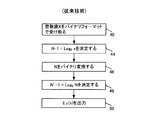
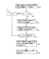
他の状況においては、デコードされたデータがエンコードされたデータの完全な復元であるという、無損失のデータ圧縮が要求される。正値整数の無損失圧縮技術として、1970年代にMIT教授のPeter Eliasによって開発されたエリアスデルタコード化(符号化)アルゴリズムが良く知られている。図1の従来技術のフローチャートを参照し、整数値x=13のエリアスデルタコード化を一例として、自然数xIN={1,2,3,・・・}をコード化する従来のエリアスデルタ技術を説明する。ステップ40では、整数データ値をバイナリフォーマットで受け取る。
13base10= 1101base2
ステップ44では、ステップ42におけるバイナリ値の桁数Nを決定する。
1011はN = 4桁を有する。
Nは、元の整数値xに含まれる最も大きな2のべき乗値の指数の整数値がN−1であるということから、数学的に決定される。別言すると、N-1= Log2 x に含まれる最大の整数、ということである。このことは、一般に、N−1= Log2 x と表記され、本明細書でもそのような表記を用いる。
N-1 = Log2 13 → N-1 = 3; N = 4.
Nを記述する他の手法は次のとおりである。即ち、Nは、xのバイナリ表記における桁数であり、N−1は、xのバイナリ表記から最上位ビット(MSB)を除外したものの桁数である。
In other situations, lossless data compression is required where the decoded data is a complete decompression of the encoded data. As a lossless compression technique for positive integers, an alias delta coding (coding) algorithm developed by Peter Elias of MIT Professor in the 1970s is well known. A conventional alias delta technique for encoding a natural number xIN = {1, 2, 3,...} Will be described with reference to the flowchart of FIG. To do. In
13 base10 = 1101 base2
In
1011 has N = 4 digits.
N is determined mathematically because the integer value of the exponent of the largest power value of 2 included in the original integer value x is N-1. In other words, N-1 = the largest integer included in Log 2 x. This is generally expressed as N−1 = Log 2 x, and this is also used in this specification.
N-1 =
Other techniques for describing N are as follows. That is, N is the number of digits in the binary notation of x, and N−1 is the number of digits of the binary notation of x excluding the most significant bit (MSB).
ステップ46では、Nをバイナリ数に変換する。
4base10= 100base2
さらにステップ48では、Nのバイナリ表記の桁数N’を決定する。
100 は、N’ = 3 の桁数を有する。 N’-1 = 2
繰り返すが、N’は、Nに含まれる最も大きな2のべき乗値の指数の整数値がN’−1であることから、数学的に決定される。
N’-1 = Log2 4 → N’-1 = 2, N’ = 3
In
4 base10 = 100 base2
In
100 has N '= 3 digits. N'-1 = 2
Again, N 'is mathematically determined because the integer value of the exponent of the largest power value of 2 included in N is N'-1.
N'-1 =
元の整数xに対するエリアスデルタコードEδ(x)は、次の3つの部分から得られる。
Eδ(x)1 = N’−1個のゼロ(ステップ48)
Eδ(x)2 = Nのバイナリ表記(ステップ42)
Eδ(x)3 = xのバイナリ表記の残りN−1桁(即ち、xのバイナリ表記からMSBを除いたもの)
それゆえ、Eδ(13)は次の(数1)のとおりである。
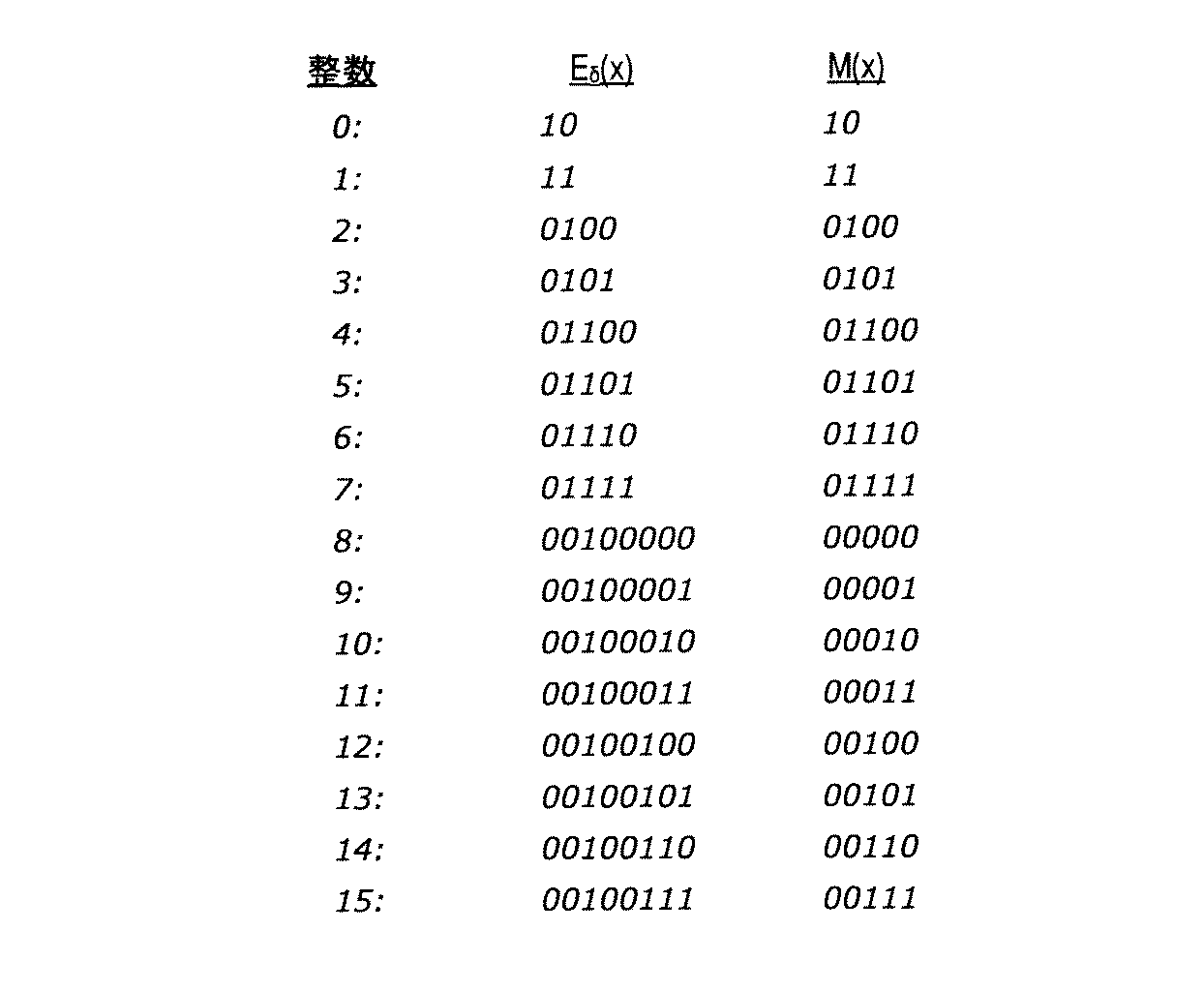
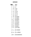
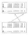
図2の従来技術は、整数0から16まで、及び、32、64、128に対するエリアスデルタコードを示している。
The alias delta code E δ (x) for the original integer x is obtained from the following three parts:
E δ (x) 1 = N′−1 zeros (step 48)
Binary representation of E δ (x) 2 = N (step 42)
E δ (x) 3 = remaining N-1 digits in binary representation of x (ie, binary representation of x minus MSB)
Therefore, E δ (13) is as follows.
The prior art of FIG. 2 shows the alias delta code for
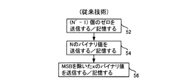
整数値に対するエリアスデルタコードが得られたら、その値はステップ50にて出力される。出力は、プロセッサから永続記憶媒体へ出力される場合があれば、プロセッサから、他のコンピュータデバイスへ送信するための通信インタフェイスへ出力される場合もある。整数値のエリアスデルタコードは、永続記憶媒体に記憶されることもあれば、単一の値として、ネットワーク接続を介して送信される場合もある。あるいは、図3の従来技術に示すように、サブコンポーネント(サブ要素)Eδ(x)1, Eδ(x)2 及び Eδ(x)3 の形式で送信される場合もある。即ち、ステップ52において、Eδ(x)1がFIFOデータ構造体に記憶されるか又は送信される。ステップ54において、Eδ(x)2がFIFOデータ構造体に記憶されるか又は送信される。そしてステップ56において、Eδ(x)3がFIFOデータ構造体に記憶されるか又は送信される。サブコンポーネントは上記した順で記憶され送信され、それらがFIFO構造体から取り出されるか受信されたときには、エリアスデルタコードの他のサブコンポーネントをデコードする必要があるそれらサブコンポーネントは、適切な順序で調べられる。エリアスデルタコード値から元の整数値を復元するために、そのエリアスデルタコード値に対して逆の操作が実行される。
Once the alias delta code for the integer value is obtained, that value is output at
エリアスデルタコード化技術の一つの課題は、あらゆる入力整数値に対して機能しなければならないことであり、それゆえ、あらゆる整数に対してコードのための容量を確保しなければならないことである。図2の例に示されているように、例えばx=64のような大きな入力値に対して、Eδ(64)は、もとのバイナリ値そのものよりも多くの記憶容量/帯域を必要とする(バイナリ値が1000000であるのに対してEδ(64)=00111000000である)。しなしながら、現実のアプリケーションの多くにおいては、入力される整数値には制限がある。例えば、レジスタには、例えば4ビットというように与えられたサイズがある。他の事例として、多くのデータクラスでは、工業規格によって定められたサイズがある。例えば、マルチメディアのストリームにおけるカラー値の送信は0から255の範囲であり、8ビットに格納される。エリアスデルタコード化は、データシステムにはしばしば制限が決められており、入力値は既知の最小値と既知の最大値を有する帯域の範囲であるという、この知見を利用してはいない。 One challenge with the Elias Delta coding technique is that it must work for every input integer value, and therefore has to reserve capacity for the code for every integer. As shown in the example of FIG. 2, for a large input value such as x = 64, E δ (64) requires more storage capacity / bandwidth than the original binary value itself. (E δ (64) = 00111000000 versus a binary value of 1000000). However, in many real-world applications, the input integer value is limited. For example, a register has a given size, for example, 4 bits. As another example, many data classes have sizes defined by industry standards. For example, transmission of color values in a multimedia stream ranges from 0 to 255 and is stored in 8 bits. Elias delta coding is often limited in data systems and does not take advantage of this finding that the input value is a range of bands with a known minimum and a known maximum.
本発明は、概略すると、送信すべき/記憶すべき整数値を、エリアスデルタコード化などの従来の圧縮技術と比較してより高い圧縮率で圧縮するシステムに関する。特に、データシステムが、最小値だけでなく最大値も有する既定の整数域に亘る整数値を記憶及び/又は送信することを用いて、最大値の、あるいは最大値に近い整数値を、データ解像度の損失なく、従来システムよりも高比率で圧縮する。本技術は、エリアスデルタコード化とパラレルの関係にある。しかしながら、記憶すべき、あるいは、送信すべきバイナリ整数値の桁数が、与えられたデータシステムに予め定められた最大桁数に等しいと判定された場合、整数値のlog(2)値のバイナリ表記の記憶及び/又は送信が、記憶又は送信から除外され、これによって、従来のエリアスデルタコード化と比較して高い圧縮率が得られる。 The present invention generally relates to a system that compresses integer values to be transmitted / stored at a higher compression rate compared to conventional compression techniques such as Elias Delta coding. In particular, the data system stores and / or transmits an integer value over a predetermined integer range that has not only a minimum value but also a maximum value, so that an integer value at or near the maximum value can be obtained from the data resolution. Compresses at a higher ratio than conventional systems without loss. This technique is in parallel with alias delta coding. However, if it is determined that the number of binary integer values to be stored or transmitted is equal to the maximum number of digits predetermined for a given data system, the integer log (2) value binary The notation storage and / or transmission is excluded from storage or transmission, which results in a higher compression ratio compared to conventional alias delta coding.
本技術の圧縮技術は、広範囲の様々なデータシステムにおける幅広いアプリケーションに適用することができる。しかしながら、一つのアプリケーションとして、本技術は、ウエブアプリケーションやウエブサイトが適切に動作することを確保するためにそれらウエブアプリケーションやウエブサイトのパフォーマンスの問題を積極的に検知し診断するアプリケーションマネージメントシステムに関連するデータを圧縮するのに用いられる。 The compression technique of the present technology can be applied to a wide range of applications in a wide variety of data systems. However, as an application, this technology is related to an application management system that actively detects and diagnoses web application and website performance issues to ensure that the web application and website operate properly. Used to compress the data to be processed.
本技術は、ハードウエア、ソフトウエア、あるいは、ハードとソフトの組み合わせで実現されてよい。本発明のためのソフトウエアは、ハードディスクドライブ、CD−ROM、DVD、光学ディスク、フロッピー(登録商標)ディスク、テープドライブ、RAM、ROM、あるいは、他の適切な記憶デバイスを含む、一つあるいはそれ以上のプロセッサ読み出し可能な記憶媒体に格納される。別の態様では、そのソフトウエアの一部あるいは全部は、カスタムIC、ゲートアレイ、FPGA、PLD、及び、特定目的のためのコンピュータを含む、専用ハードウエアで置き換えられ得る。一つの態様では、本発明が実装されたソフトウエアは、一つあるいはそれ以上のプロセッサをプログラムするのに用いられる。そのプロセッサは、一つあるいはそれ以上の、記憶デバイス、周辺装置、及び/又は、通信インタフェイスと通信し得る。 The present technology may be realized by hardware, software, or a combination of hardware and software. The software for the present invention includes one or more of hard disk drives, CD-ROMs, DVDs, optical disks, floppy disks, tape drives, RAM, ROM, or other suitable storage devices. It is stored in the above processor-readable storage medium. In another aspect, some or all of the software may be replaced with dedicated hardware, including custom ICs, gate arrays, FPGAs, PLDs, and special purpose computers. In one embodiment, software in which the present invention is implemented is used to program one or more processors. The processor may communicate with one or more storage devices, peripheral devices, and / or communication interfaces.
図4〜11を参照して本技術を説明する。それは、一般的に、既知の可能な整数域内の範囲に亘る整数データを圧縮するシステムに関する。本技術の実施例は、特に、予め定められた整数域の上限に近い高次整数値を圧縮するのに効果的であるので、本技術の実施例を、本明細書では、「高次圧縮技法」と称する。ウエブアプリケーションとウエブサイトが適切に実行されるようにそれらのパフォーマンスについての問題を検知し診断するSOAアプリケーションを参照し、以下、高次圧縮技法を用いる一つの特定システムを説明する。そのようなアプリケーションマネジメントシステムの一つに、カリフォルニア州サウスサンフランシスコのCA, Inc., Wily Technology DivisionによるIntroscope(登録商標)がある。図10のブロック図を参照してそのようなシステムを以下にて説明する。しかしながら、本明細書で説明する高次圧縮技法は、予め定められた整数域の範囲に亘る整数値が送信及び/又は記憶される広範囲に及ぶ様々なソフトウエアアプリケーションに適用することができる。 The present technology will be described with reference to FIGS. It generally relates to a system for compressing integer data over a range within a known possible integer range. Since the embodiments of the present technology are particularly effective for compressing high-order integer values close to the upper limit of the predetermined integer range, the embodiments of the present technology are referred to as “high-order compression” in this specification. It is called "technique". One specific system that uses higher order compression techniques is described below with reference to SOA applications that detect and diagnose problems with their performance so that the web application and website run properly. One such application management system is Introscope® by CA, Inc., Wily Technology Division, South San Francisco, California. Such a system is described below with reference to the block diagram of FIG. However, the high-order compression techniques described herein can be applied to a wide variety of software applications in which integer values over a predetermined range of integer ranges are transmitted and / or stored.
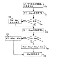
図4に、本技術の高次圧縮技法の実施例による整数値をエンコードするためのフローチャートを示す。この技法は、記憶/送信される整数値の取り得る範囲が最小値(たとえばゼロ)と所定の最大値で制限されているデータシステムにおいて整数値を圧縮するのに用いることができる。その範囲の最小整数値の典型はゼロであるが、他の実施形態では最小値はゼロである必要はない。 FIG. 4 shows a flowchart for encoding integer values according to an embodiment of the high-order compression technique of the present technology. This technique can be used to compress integer values in data systems where the possible range of stored / transmitted integer values is limited by a minimum value (eg, zero) and a predetermined maximum value. The smallest integer value in the range is typically zero, but in other embodiments the minimum value need not be zero.
最大整数値に関していえば、多くのデータシステムやソフトウエアアプリケーションは、システムの制約によって通常は制限されるデータ値の範囲を扱う。例えば、データシステムは、レジスタ、アドレスバス、データバスを用いており、それらは、例えば、0から15までの間の16個の整数値を扱い得る4ビットといった、予め決められたサイズ、セット数を扱う。他の例として、多くのアプリケーションプログラムは、工業規格によって定められているサイズとフォーマットのデータを送信し記憶する。多くの例の一つとしては、ビットマップ画像やビデオフレームバッファにおけるピクセルの色を表すデータは、8ビットフォーマットでの256個の値の一つとしてしばしば送信され記憶される。他の通信、オーディオ、及び、ビデオのデータは、標準的な8ビット、16ビット、などのデータ長で記憶される。 In terms of maximum integer values, many data systems and software applications deal with a range of data values that are usually limited by system constraints. For example, the data system uses registers, address buses, and data buses, which have a predetermined size, number of sets, eg, 4 bits that can handle 16 integer values between 0 and 15. Handle. As another example, many application programs send and store data of size and format defined by industry standards. As one of many examples, data representing the color of a pixel in a bitmap image or video frame buffer is often transmitted and stored as one of 256 values in an 8-bit format. Other communication, audio, and video data is stored in standard 8-bit, 16-bit, etc. data lengths.
高次圧縮技法の実施例では、送信され記憶される整数値は、既知の最大値を有する整数域内のものであると仮定する。この最大値の情報は、以下で説明するように、高次圧縮技法を実装するエンコードエンジンとデコードエンジンにて用いられ、圧縮されたデータの圧縮率を向上する。実施例において、本システムは、2iに等しい最大整数値の元で動作する。ここで、iは、2のべき乗である(i=2、4、8、16、32、64・・・)。しかしながら、本システムの他の実施形態は、別の整数値範囲のデータを圧縮/デコードするように動作する。 In an embodiment of the higher order compression technique, it is assumed that the transmitted and stored integer values are in the integer range with the known maximum value. As will be described below, this maximum value information is used in an encoding engine and a decoding engine that implement a high-order compression technique, and improves the compression rate of the compressed data. In an embodiment, the system operates with a maximum integer value equal to 2 i . Here, i is a power of 2 (i = 2, 4, 8, 16, 32, 64...). However, other embodiments of the system operate to compress / decode data in another integer value range.
図4のフローチャートを参照して、本システムの実施例を説明する。この処理は、4ビットで送信/記憶される16個までの異なる整数値を送信あるいは記憶するデータシステムにて用いられる。それゆえ、その整数域内の整数値をバイナリ表記で表す際のビットの最大数は4ビットである。上述したように、本技術は、バイナリの桁数の最大数がそれよりも大きい、あるいは小さい他の実施形態のデータシステムでも用いることができる。本明細書においては、バイナリ表記したときの桁数が、与えられたデータシステムにて許容される最大桁数と同じである整数値を「高次整数値」と称する。例えば、この高次圧縮技法は、最大4ビットを占める16個の整数値を扱うシステムで用いられる。そのようなシステムでは、8(1000base2)から15(1111base2)までの整数値が高次の整数値と称される。その同じ整数値であっても、例えば8ビットで256個の整数値を扱うシステムにおいては、高次の整数値とは見なされない。 An embodiment of the present system will be described with reference to the flowchart of FIG. This process is used in data systems that transmit or store up to 16 different integer values transmitted / stored in 4 bits. Therefore, the maximum number of bits when representing an integer value in the integer range in binary notation is 4 bits. As described above, the present technology can also be used in other embodiments of the data system in which the maximum number of binary digits is larger or smaller. In the present specification, an integer value in which the number of digits in binary notation is the same as the maximum number of digits allowed in a given data system is referred to as a “high-order integer value”. For example, this higher order compression technique is used in a system that handles 16 integer values occupying up to 4 bits. In such a system, integer values from 8 (1000 base2 ) to 15 (1111 base2 ) are referred to as high-order integer values. Even the same integer value is not regarded as a higher-order integer value in a system that handles 256 integer values with 8 bits, for example.
以下で説明する高次圧縮技法は、エンコードエンジン230(図10)にて実行される。説明の目的をもって、最大16個の整数値を許容するデータシステムにおいて任意に選択された整数値x=14をエンコードする場合について、図4のフローチャートを説明する。しかしながら、そのようなデータシステムにおいて、本技術は、16個の取り得る整数値のいずれであっても受け取ってエンコードできることが理解されるであろう。ステップ100では、エンコードエンジンはバイナリ形式の整数値xを受信する。この例では、
x=14base(10)=1110base(2)
である。
The high-order compression technique described below is performed by the encoding engine 230 (FIG. 10). For purposes of explanation, the flowchart of FIG. 4 will be described for encoding an arbitrarily chosen integer value x = 14 in a data system that allows up to 16 integer values. However, it will be appreciated that in such a data system, the technique can receive and encode any of the 16 possible integer values. In
x = 14 base (10) = 1110 base (2)
It is.
ステップ104では、エンコードエンジン230は、その整数のバイナリ値の桁数Nを決定する。「背景」の欄で説明したように、このときNは、N-1 = log2 x より決定される。
N-1 = log2 14 → N-1 = 3, N = 4
本技術分野の当業者であれば、整数値のバイナリ表記の桁数を決定する代替方法あるいは付加的な方法を理解することもあろう。
In
N-1 = log 2 14 → N-1 = 3, N = 4
Those skilled in the art will understand alternative or additional methods for determining the number of digits in the binary representation of an integer value.
ステップ106では、エンコードエンジン230は、Nが既知の整数域のlog2の最大値に等しいか否かを判断する。この例では、Nの最大値は4である。整数値x=4の場合Nは4に等しいので、エンコードエンジンは、ステップ108にて、受信した整数値に対するNが既定の最大値に等しいことを示すフラグを設定する。このフラグを設定することは、図4では、「CHK = max」で表されている。ステップ106におけるNの値が最大値よりも小さい場合は、ステップ108はスキップされる。ステップ114では、Nのバイナリ表記(4base10 = 100base2)を用い、Nのバイナリ表記における桁数N’を決定する。
N’-1 = log2 N
N’-1 = log2 4 → N’-1 = 2, N’ = 3.
繰り返すが、本技術分野の当業者であれば、Nのバイナリ表記の桁数を決定する代替方法あるいは付加的な方法を理解することもあろう。
In
N'-1 = log 2 N
N'-1 =
Again, one of ordinary skill in the art will understand alternative or additional methods for determining the number of digits in the binary representation of N.
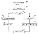
ステップ114以降、エンコードエンジンは高次圧縮値を決定する。ここでは高次圧縮値をM(x)で表す。整数値xが既定の最大値よりも小さい桁数Nを有する場合(即ち、ステップ118においてCHKがmaxに等しくない場合)、高次圧縮値M(x)は、ステップ120にてエリアスデルタ値と同じように決定される。即ち、高次圧縮値M(x) = M(x)1に(M(x)1の後ろに)M(x)2を付加し、さらに(M(x)2の後ろに)M(x)3を付加したものである。ここで、
M(x)1 = N’ - 1 個のゼロ(ステップ114);
M(x)2 = xのバイナリ表示におけるビット数N(ステップ104);
M(x)3 = xのバイナリ表記の残りN-1桁(即ち、xのバイナリ表記からMSBを除いたもの)
である。
After
M (x) 1 = N '-1 zero (step 114);
M (x) 2 = number of bits N in binary representation of x (step 104);
M (x) 3 = remaining N-1 digits in binary representation of x (ie, binary representation of x minus MSB)
It is.
しかしながら、ステップ118において、整数値xが既定の整数値の範囲における最大ビット数を用いるものである場合、本システムは、エリアスデルタコード化技法のような従来の圧縮技法に比較して、エンコードされた値のサイズを低減する。ステップ124では、フラグが最大値に等しい場合、高次圧縮値M(x) = M(x)1に(M(x)1の後に)M(x)3を付加したものとなる。ここで、
M(x)1 = N’ - 1 個のゼロ(ステップ114)
M(x)3 = xのバイナリ表記の残りN-1桁(即ち、xのバイナリ表記からMSBを除いたもの)
である。
However, in
M (x) 1 = N '-1 zero (step 114)
M (x) 3 = remaining N-1 digits in binary representation of x (ie, binary representation of x minus MSB)
It is.
理解されるように、受信した整数値のバイナリ表記が、既定の範囲についての最大桁数を有する場合、最上位ビットを表す符号化値(即ちM(x)2)のための容量を確保する必要がない。 As will be appreciated, if the binary representation of the received integer value has the maximum number of digits for a predefined range, then reserve capacity for the encoded value representing the most significant bit (ie, M (x) 2 ). There is no need.
x=14とするこの事例では、バイナリ表記におけるビット数(即ち、4)は、既定の最大値に等しい。従って、
M(14) = M(14)1にM(14)3を付加したもの
M(14)1 = N’ - 1 個のゼロ、即ち2個のゼロ → M(14)1 = 00;
M(14)3 = xのバイナリ表記からMSBを除いた残りN-1桁
x = 14のバイナリ表記は 1110 → M(14)3 = 110
M(14) = M(14)1 に M(14)3を付加したもの
M(14) = 00110
となる。
In this case where x = 14, the number of bits in binary notation (ie, 4) is equal to a predetermined maximum value. Therefore,
M (14) = M (14) 1 plus M (14) 3
M (14) 1 = N '-1 zero,
M (14) 3 = remaining N-1 digits excluding MSB from binary representation of x
The binary notation for x = 14 is 1110 → M (14) 3 = 110
M (14) = M (14) 1 plus M (14) 3
M (14) = 00110
It becomes.
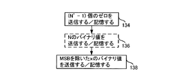
ステップ130では、高次圧縮値M(x)が出力される。この出力は、プロセッサから永続的記憶媒体への出力であったり、プロセッサから、他のコンピュータデバイスへの転送のための通信インタフェイスへの出力であったりする。整数値に対する高次圧縮値は、永続的記憶媒体に記憶されたり、単一の値としてネットワーク接続を介して転送され得る。あるいは、図5に示されているように、それはサブコンポーネントM(x)1, M(x)2 (場合によっては) M(x)3.として転送/記憶されることもある。即ち、M(x)1は、ステップ134にて、転送されるか、あるいはFIFOデータ構造体に格納される。その整数値のバイナリ表記が既定の最大桁数のものではない場合、ステップ136にて、M(x)2が転送されるかあるいはFIFOデータ構造体に格納される。そうでない場合は、ステップ136はスキップされる。ステップ138にて、M(x)3が送信されるかあるいはFIFOデータ構造体に格納される。サブコンポーネントは上記した順で記憶され送信され、それらがFIFO構造体から取り出されるか受信されたときに、高次圧縮値の他のサブコンポーネントをデコードする必要があるそれらサブコンポーネントは、適切な順序で調べられる。
In
あるいはサブコンポーネントは、転送されるか又はLIFOデータ構造体に格納され得る。その場合、サブコンポーネントは、上述した場合とは逆順で送信又は格納される。 Alternatively, the subcomponent can be transferred or stored in a LIFO data structure. In that case, the subcomponents are transmitted or stored in the reverse order as described above.
さらに、上記説明した図4のステップは、上記したステップの結果と同じ結果が得られる他の概念的方法によって行われてもよい。そのような代替方法を図4Aに示す。図4Aは、図4と類似しているが、Nが既定の最大値と同じか否かのチェックが省かれている。その代り、上記説明したように、システムは、ステップ106にて、Nが高次のものであるか否かをチェックする。もしそうであれば、システムは、上記したとおり、ステップ107にて、N’-1 = log2 N を用い、Nのバイナリ表記における桁数N’を決定し、ステップ109にて、M(x)1の後に M(x)3 を付け加えて M(x) を設定する。ここで、M(x)1 と M(x)3は上記説明したとおりである。ステップ106にて、Nが高次のものでないと判定された場合、システムは、上記したとおり、ステップ111にて、N’-1 = log2 N を用い、Nのバイナリ表記における桁数N’を決定し、ステップ113にて、M(x)1の後に M(x)2 を付けさらにその後に M(x)3を付け加えて M(x) を設定する。ここで、M(x)1 と M(x)2と M(x)3は上記説明したとおりである。次いで上記説明したとおりステップ130にてM(x) が出力される。繰り返すが、この技術分野の当業者であれば、上記開示した方法のさらに別の方法を見出し得るであろう。
Further, the above-described steps of FIG. 4 may be performed by other conceptual methods that obtain the same results as the above-described steps. Such an alternative method is shown in FIG. 4A. FIG. 4A is similar to FIG. 4 except that the check whether N is the same as the default maximum is omitted. Instead, as explained above, the system checks at
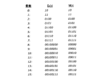
図6は、整数値が0から15の範囲に属するシステムのテーブルを示す。図に示されているように、下位の整数値(例えば、x≦7、及び、N<最大値4)については、高次圧縮値M(x)はエリアスデルタ値Eδ(x)と同じである。しかしながら、バイナリ表記が最大ビット数である整数値(8≦x≦15、及び、N=最大値4)については、本圧縮技法M(x)は、整数値の転送及び/又は記憶に際して、エリアスデルタコードよりも容量の低減を提供する。 FIG. 6 shows a table of systems belonging to the range of integer values from 0 to 15. As shown in the figure, for lower integer values (eg, x ≦ 7 and N <maximum value 4), the higher order compression value M (x) is the same as the alias delta value E δ (x). It is. However, for integer values where the binary representation is the maximum number of bits (8 ≦ x ≦ 15 and N = maximum value 4), the compression technique M (x) is aliased when transferring and / or storing integer values. Provides capacity reduction over delta code.
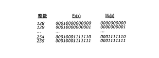
図7は、0から255の範囲に属する整数値(バイナリ表記の最大桁数=8)に対する高次圧縮技法の例を示す。この例では、0から127の範囲の整数値は、エリアスデルタ値と同じ方法で計算された高次圧縮値となる。しかしながら、128から255の範囲の整数値(そのいくつかが図7に示されている)については、それらの整数は最大ビット桁数をとり、それらの高次圧縮値は、エリアスデルタコード化法と比較して桁数の低減が図れる。図に示されているとおり、128から255の範囲の整数に対してはエリアスデルタコードは14桁を要するが、128から255の範囲の整数に対する高次圧縮値はたった9桁で済む。このことは、記憶容量と転送帯域の顕著な節約を提供する。
FIG. 7 shows an example of a high-order compression technique for integer values (maximum number of digits in binary notation = 8) belonging to the range of 0 to 255. In this example, an integer value in the range of 0 to 127 is a high-order compression value calculated in the same manner as the alias delta value. However, for integer values in the range of 128 to 255 (some of which are shown in FIG. 7), those integers take the maximum number of bit digits and their higher-order compression values are calculated using the alias delta encoding method. Compared with, the number of digits can be reduced. As shown in the figure, for an integer in the
エンコードされた値が転送にて受信されるか、永続記憶装置から取り出されると、エンコードされた値はデコードされる。本システムは、さらに、デコードエンジン232(図10)を備えている。デコードエンジン232は、上記した高次圧縮技法の逆を行うことができ、エンコードされた値を元の整数値に変換する。図8のフローチャートを参照してデコードエンジン232の処理を説明する。デコードエンジン232は、エンコードエンジン230と同じ既定の最小値と最大値を使って動作する。それゆえ、図8の例において、デコードエンジン232は、エンコードエンジン230と同じ整数域に対して動作するように構成されている。上記の例において、値は0から15の範囲であり、バイナリ表記における最大桁数Nは4である。図4において、M(14)=00110であった。図8にて、記憶/受信された値00110のデコード(復号)を説明する。しかしながら、上記と同様に、デコードエンジンは、既定の整数範囲のどの値であってもデコードできる点が理解されるであろう。 When the encoded value is received on transfer or retrieved from persistent storage, the encoded value is decoded. The system further includes a decode engine 232 (FIG. 10). The decode engine 232 can perform the inverse of the higher order compression technique described above and converts the encoded value to the original integer value. The processing of the decoding engine 232 will be described with reference to the flowchart of FIG. The decode engine 232 operates using the same default minimum and maximum values as the encode engine 230. Therefore, in the example of FIG. 8, the decoding engine 232 is configured to operate on the same integer range as the encoding engine 230. In the above example, the value is in the range of 0 to 15, and the maximum number of digits N in binary notation is 4. In FIG. 4, M (14) = 00110. The decoding of the stored / received value 0110 will be described with reference to FIG. However, as noted above, it will be understood that the decode engine can decode any value within a predetermined integer range.
デコードエンジン232は、扱う高次圧縮値M(x)の全部を受信することがあれば、FIFO又はLIFOデータ取得構造体から第1のコンポーネントM(x)1を受信することもある。いずれの場合であっても、ステップ140において、デコードエンジンは、受信したあるいは記憶された値M(x) における先頭のゼロの並びである第1のコンポーネントM(x)1を受信する。前の説明と同じように、先頭に並ぶゼロの個数を以下、N’-1と称することにする。
M(x)=00110の場合、先頭に2個のゼロの並びがある → N’-1=2, 及び N’=3
The decode engine 232 may receive the first component M (x) 1 from the FIFO or LIFO data acquisition structure if it receives all of the higher order compressed values M (x) it handles. In any case, in
If M (x) = 00110, there is a sequence of two zeros at the beginning → N'-1 = 2, and N '= 3
高次圧縮値において、先頭に並ぶゼロの個数N’-1 は、次の関係によってデコードされるバイナリ値の最上位ビットNを示す。
N’-1 = Log2 N
整数値が0から15の間に制限されているシステムにおいて、先頭にゼロが付いていないことは、整数値が0と1の間であることを示し、先頭にゼロが1個の場合は整数値が2から7の間であることを示し、先頭にゼロが2個(あるいはそれ以上)並んでいる場合は整数値が8から15の間であることを示す。
In the high-order compressed value, the number N′−1 of zeros arranged at the head indicates the most significant bit N of the binary value decoded by the following relationship.
N'-1 = Log 2 N
In systems where integer values are restricted between 0 and 15, the absence of a leading zero indicates that the integer value is between 0 and 1, with an integer leading at zero. The numerical value indicates that it is between 2 and 7, and if two zeros (or more) are arranged at the beginning, it indicates that the integer value is between 8 and 15.
上記の例では、整数値は0から15の間に制限されている(Nの最大値は4である)。しかしながら、上記で示したように、本発明は、いかなる既知の整数域に対しても動作する。実施例においては、既知の整数域における最大の整数値は、2iに等しい。ここで、iは、2のべき乗である(i=2,4,8,16,32,64・・・)。それゆえ、実施例においては、この高次圧縮技法は、2値、4値、16値(上記の例のとおりである)、256値、65536値の整数域を扱うものである。 In the above example, the integer value is limited to between 0 and 15 (the maximum value of N is 4). However, as indicated above, the present invention operates on any known integer range. In an embodiment, the largest integer value in the known integer range is equal to 2 i . Here, i is a power of 2 (i = 2, 4, 8, 16, 32, 64...). Therefore, in the embodiment, this high-order compression technique deals with integer ranges of binary, 4-value, 16-value (as in the above example), 256-value, 65536-value.
高次圧縮値の先頭に並ぶゼロの個数が、そのデータシステムにおける最大整数値のバイナリ表記の桁数の log2 の値以上である場合はいつでも、その高次圧縮値は、そのデータシステムにおけるバイナリ表記最大桁数を要する整数値を表す。従って以下のことが言える。
・0から3までの整数域の場合、与えられた高次圧縮値がその先頭に1個のゼロを有することは、その与えられた高次圧縮値がバイナリ表記で最大桁数N=2ビットを要する整数値であることを示す。
・0から15までの整数域の場合(上述の場合)、与えられた高次圧縮値がその先頭に2個のゼロを有することは、その与えられた高次圧縮値がバイナリ表記で最大桁数N=4ビットを要する整数値であることを示している。
・0から255までの整数域の場合、与えられた高次圧縮値がその先頭に3個のゼロを有することは、その与えられた高次圧縮値がバイナリ表記で最大桁数N=8ビットを要する整数値であることを示している。
・0から65535までの整数域の場合、与えられた高次圧縮値がその先頭に4個のゼロを有することは、その与えられた高次圧縮値がバイナリ表記で最大桁数N=16ビットを要する整数値であることを示している、等々。
このような技法と整数域の情報を用いることによって、デコードエンジン232は、高次圧縮値の先頭のゼロの個数だけから、その高次圧縮値がバイナリで最大桁数を要する数値を表していることを判断することができる。
Whenever the number of zeros at the beginning of a higher-order compressed value is greater than or equal to the log 2 value of the binary number of the largest integer value in the data system, the higher-order compressed value is binary in the data system. Represents an integer value that requires the maximum number of digits. Therefore, the following can be said.
-In the case of an integer range from 0 to 3, a given high-order compressed value has a leading zero, which means that the given high-order compressed value is binary notation and the maximum number of digits is N = 2 bits. Indicates an integer value requiring.
-In the case of an integer range from 0 to 15 (in the above case), the given high-order compressed value has two zeros at the beginning, which means that the given high-order compressed value is the largest digit in binary notation. The number N is an integer value that requires 4 bits.
・ In the integer range from 0 to 255, the given high-order compressed value has three leading zeros. The given high-order compressed value is binary notation and the maximum number of digits is N = 8 bits. It is an integer value that requires.
-In the case of an integer range from 0 to 65535, the given high-order compressed value has four zeros at the beginning, which means that the given high-order compressed value is binary notation and the maximum number of digits N = 16 bits. Indicates an integer value that requires.
By using such a technique and information in the integer range, the decoding engine 232 represents a numerical value in which the high-order compressed value is binary and requires the maximum number of digits from only the number of leading zeros of the high-order compressed value. Can be judged.
整数値が0から15の範囲である図8の例を続ける。ステップ140では、デコードエンジンは先頭のゼロの個数を読む。ステップ144では、先頭に2個以上のゼロが存在すると判定された場合(N’-1 が2以上である場合)、デコードエンジンは、自動的に、その整数値は8から15の間であり、その整数値のバイナリ表記のビット数Nが4であると判断する。従って、ステップ144にて、N’-1が2以上であると判定された場合、ステップ146にてNに4がセットされ、148−150(後述)のステップはスキップされる。
Continuing with the example of FIG. 8 where the integer value is in the range of 0 to 15. In
ステップ152では、第1の中間十進数値Jが、2N-1として決定される。Jは、最上位ビットの十進数表記を表す。M(x) = 00110の例では、N=4である。それゆえ、
J = 2N-1 = 23= 8
である。ステップ158では、受信/記憶された値M(x) から最上位ビットを除いたものを十進数へ変換し、第2の中間十進数値Kが決定される。これは、M(x)の後ろのN-1ビットである。上記のM(x) = 00110の例では、N=4と決定される。それゆえ、N-1 = 3 であり、M(x)の後ろの3桁は110である。従って、この例におけるM(x) のN-1桁の十進数変換値Kは次のとおり与えられる。
110base2 = Kbase10→ K = 6
In
J = 2 N-1 = 2 3 = 8
It is. In
110 base2 = K base10 → K = 6
最後にステップ160にて、元の整数値xは、中間値JとKを加算して決定される。
x = J + K
x = 8 + 6 = 14
図4から理解されるように、高次圧縮技法によって整数値14はM(14) = 00110にエンコードされる。図8から理解されるように、高次圧縮値 00110 は、元の整数値14にデコードされる。
Finally, at
x = J + K
x = 8 + 6 = 14
As can be seen from FIG. 4, the high order compression technique encodes the
上記の説明において、先頭のゼロの並びが、デコードするバイナリ値が最大ビット数を有していることを示している場合、ステップ148と150はスキップされ、このことは処理時間の低減をもたらすことに留意されたい。ただし、バイナリ表記における桁数が最大値よりも少ないと判定された場合には、ステップ148と159が実行される。例えば、最大ビット数が4であるシステム(その整数域内で16個の整数値が取り得るシステム)において、デコードエンジン232が高次圧縮値M(x)=01101を受信した場合を仮定する。その場合、ステップ140にて先頭に1個のゼロがあり、N’-1は2以上ではない。従って、デコードエンジンは、ステップ148を実行し、M(x)において先頭のゼロの並びに続くN’個のビットを読み出す。01101を復号化するこの例の場合、先頭に1個のゼロがあり、従ってN’-1 = 1であり、N’ = 2である。従って、M(x)において先頭のゼロに続く2ビットが読まれる。M(x) = 01101をデコードするこの例の場合、それら桁は「11」である。ステップ150では、Nは、読み出したN’個のビットの十進法への変換に等しい。この例の場合は、
11base2 = 3base10 → N = 3
である。
In the above description, if the leading zero sequence indicates that the binary value to decode has the maximum number of bits,
11 base2 = 3 base10 → N = 3
It is.
前述したように次いでステップ152が実行される。第1の中間値Jは、N=3として、次のとおり決定される。
J = 2N-1 =22 = 4
Step 152 is then performed as described above. The first intermediate value J is determined as follows with N = 3.
J = 2 N-1 = 2 2 = 4
ステップ158では、第2の中間地Kが決定される。上記に示したように、Kは、受信/記憶された値 M(x) から最上位ビットを除いた残りの部分、即ち、M(x)の最後のN-1桁、の十進法への変換である。M(x) = 01101である上記例では、N=3であることが決定されている。即ち、N-1 = 2 であり、M(x)の最後の2桁は「01」である。従って、この例におけるM(x)のN-1桁の十進法への変換であるKは次のとおり与えられる。
01base2 = Kbase10 → K = 1
In
01 base2 = K base10 → K = 1
最後に、ステップ160にて、中間値JとKが加算され、元の整数値xが求まる。
x = J + K
x = 4 + 1 = 5
Finally, in
x = J + K
x = 4 + 1 = 5
上記説明した図8のステップは、上記したステップの結果と同じ結果が得られる、他の概念的な方法によって実行されてもよいことが理解されるであろう。 It will be appreciated that the steps of FIG. 8 described above may be performed by other conceptual methods that yield the same results as the steps described above.
上記説明したように、実施例では、いかなる既知の整数域であっても、N=2iを満足する最大バイナリ桁数Nを有する。ここで、iは2のべき乗である。この制約によって、デコーダ(復号器)が、エンコードされた高次圧縮値がその既知の整数域における高次整数値を表しているか否かを自動的に判定することができるようになる。iが2のべき乗であるという制約のないシステムでは、先頭のゼロの数に基づいたNに関する仮定が成立しないので、高次圧縮値の復号化はより複雑になるであろう。例えば、Nが2iに制限されており、取り得る整数値が16個であるシステムにおいては、M(x)の先頭に2個のゼロが存在すれば、N’-1 = 2 であり、N’ は、100base2 あるいは N = 4base 10 に等しい3ビットのバイナリ値であることが判る。 As described above, the embodiment has a maximum number of binary digits N satisfying N = 2 i in any known integer range. Here, i is a power of 2. This constraint allows a decoder (decoder) to automatically determine whether the encoded higher order compressed value represents a higher order integer value in its known integer range. In a system that does not have the constraint that i is a power of 2, the assumption about N based on the number of leading zeros will not hold, so decoding of higher-order compressed values will be more complicated. For example, in a system where N is limited to 2 i and there are 16 possible integer values, if there are two zeros at the beginning of M (x), then N′−1 = 2. It can be seen that N ′ is a 3-bit binary value equal to 100 base2 or N = 4 base 10 .
しかしながら、取り得る整数値は16個ではあるがNが2iに制限されていないシステムにおいては、先頭に2個のゼロが存在すればN = 4であると仮定することはできないのである。例えば、M(x)の先頭に2個のゼロが存在する場合、N’-1 = 2 であり、N’ は3ビットのバイナリ値であるが、それは、100 (N = 4)、101 (N = 5)、 110 (N = 6)、或いは、 111 (N = 7 )のいずれかを取り得る。 However, in a system in which there are 16 possible integer values but N is not limited to 2 i , it cannot be assumed that N = 4 if there are two leading zeros. For example, if there are two zeros at the beginning of M (x), N'-1 = 2 and N 'is a 3-bit binary value, which is 100 (N = 4), 101 ( N = 5), 110 (N = 6), or 111 (N = 7) can be taken.
しかしながら、より複雑であるにしても、この高次圧縮技法の実施例は、Nが2i(iは2のべき乗である)に制限されていないNの値を扱うことはできる。これは、そのような値をエンコードしたM(x) が、Nの取り得る値の夫々に対して一意に定まるからである。そのような実施例においては、符号化された値M(x)における先頭のゼロだけではNの値を決定することはできないが、M(x)の他の桁を調べる付加的なステップを実行して、M(x)を元の整数値にデコードすることはできる。 However, although more complex, this embodiment of the higher-order compression technique can handle N values where N is not limited to 2 i (i is a power of 2). This is because M (x) encoding such a value is uniquely determined for each possible value of N. In such an embodiment, the leading zero in the encoded value M (x) alone cannot determine the value of N, but performs an additional step of examining other digits in M (x) Thus, M (x) can be decoded to the original integer value.
実施例においては、高次圧縮技法は、高次整数値を符号化するには効率がよいが、高次整数値よりも下位の整数値に対してはそうでもない。他の実施形態では、高次圧縮技法によるエンコードに先立って、所定の整数域内の整数値に所定の定数を加算及び/又は除算するという、既知の正規化(regularization)技術を採用することによって、この課題に対処し得る。その定数は、その整数域のサイズに依存する。16値の整数域である上記した図6の例においては、その整数域の最上位において値をエンコードするビット数が、下位の値を符号化するのに必要なビットよりも小さくないので、この正規化ステップは、その利益を生じないことに留意されたい。この状況は、整数域が大きい場合ではない。 In embodiments, higher order compression techniques are efficient for encoding higher order integer values, but not for integer values lower than the higher order integer values. In other embodiments, by employing a known regularization technique of adding and / or dividing a predetermined constant to an integer value within a predetermined integer range prior to encoding by a higher order compression technique, This issue can be addressed. The constant depends on the size of the integer range. In the example of FIG. 6 described above, which is a 16-valued integer range, the number of bits for encoding a value at the highest order of the integer range is not smaller than the bits necessary to encode the lower value. Note that the normalization step does not yield that benefit. This situation is not the case when the integer range is large.
例えば、正規化された高次圧縮技法の利点は、図9から明らかである。図9は、8ビット整数域(256個の整数値)に亘る整数値符号化の一部を示している。正規化されていないバージョンでは、高次圧縮技法は、64から127の範囲で値を符号化するのに、128を符号化する場合よりも多くのビットを使う。例えば、所定の値の範囲では、これは準最適である。正規化プロセスでは、例えば、128から255を表すビットコードを32から159を表すコードの代わりに用い、32から127を表すビットコードを160から255を表すコードの代りに用いることによって、この問題に対処し得る。このことは、エンコード/デコードの過程で定数(その値は、その特定の整数域の範囲に依存する)を加算及び/又は減算することによって達成し得る。図9の例では、32から159の間のいずれの値にも、正規化していない高次圧縮エンコードに先立って96が加算され、160から255の間のいずれの値にも、正規化していない高次圧縮エンコードに先立って128が減算されている。このシフトの後、上記した高次圧縮技法が実行される。デコードに際してはその逆が実行される。 For example, the benefits of normalized higher order compression techniques are apparent from FIG. FIG. 9 shows part of an integer value encoding over an 8-bit integer range (256 integer values). In the non-normalized version, higher order compression techniques use more bits to encode values in the range of 64 to 127 than when encoding 128. For example, for a given range of values, this is suboptimal. The normalization process addresses this problem by, for example, using a bit code representing 128 to 255 instead of a code representing 32 to 159 and using a bit code representing 32 to 127 instead of a code representing 160 to 255. It can be dealt with. This can be achieved by adding and / or subtracting constants (the value of which depends on the range of that particular integer range) during the encoding / decoding process. In the example of FIG. 9, 96 is added to any value between 32 and 159 prior to unnormalized high-order compression encoding, and is not normalized to any value between 160 and 255. 128 is subtracted prior to high-order compression encoding. After this shift, the high-order compression technique described above is performed. The reverse is performed when decoding.
上述したように、高次圧縮技法の実施例は、整数データが記憶及び/又は転送される広範囲の様々な状況で用いられる。図10のブロック図を参照して、高次圧縮技法が用いられる1実施例を以下で説明する。このシステムは、“Transaction Tracer” と題する、2002年12月12日に出願された米国特許出願第10/318,272号により詳しく記載されている。その出願は、本技術の所有者に譲渡されている。その出願は、参照によりその全てが本明細書に組み込まれる。一般に、そのようなシステムは、コンピューティング環境におけるトランザクションをモニタする。1以上のトランザクションの組についてのデータが収集される。このデータは次いで、一組の評価に対してテストされる。評価に適合するトランザクションが報告される。一実施形態では、評価に適合しないトランザクションのデータは破棄される。報告されたデータは、ソフトウエアのどの部分が実行が遅いのか、あるいは、適切に機能していないのか、を特定するために用いられる。 As mentioned above, embodiments of higher order compression techniques are used in a wide variety of situations where integer data is stored and / or transferred. One embodiment in which higher order compression techniques are used will be described below with reference to the block diagram of FIG. This system is described in more detail in US patent application Ser. No. 10 / 318,272, filed Dec. 12, 2002, entitled “Transaction Tracer”. The application is assigned to the owner of the technology. That application is incorporated herein by reference in its entirety. In general, such systems monitor transactions in a computing environment. Data is collected for one or more transaction sets. This data is then tested against a set of evaluations. Transactions that meet the evaluation are reported. In one embodiment, data for transactions that do not match the evaluation are discarded. The reported data is used to identify which parts of the software are running slowly or not functioning properly.
一実施形態では、ユーザは、閾値追跡時間を設定するとともに、ソフトウエアシステム上で実行されている一つ、幾つか、あるいは全てのトランザクションについてトランザクション追跡を起動することができる。グラフィカルユーザインタフェイスを使って、実行時間が閾値追跡時間を超えているトランザクションがユーザに報告される。グラフィカルユーザインタフェイスは、追跡されたトランザクションにおいてどこで時間が費やされているか、ユーザが直ちに理解できるように、トランザクションについての報告をビジュアライズすることを含む。 In one embodiment, the user can set a threshold tracking time and activate transaction tracking for one, several, or all transactions running on the software system. Using the graphical user interface, transactions whose execution time exceeds the threshold tracking time are reported to the user. The graphical user interface includes visualizing reports about the transaction so that the user can immediately understand where time is spent in the tracked transaction.
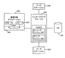
図10はアプリケーションパフォーマンスマネジメントツールのコンポーネントの概念図である。この図は、トランザクションモニタリングシステムによってモニタされる、管理対象アプリケーション200を示している。トランザクションモニタリングシステムは、管理対象アプリケーション200のバイトコードにプローブ202、204を付加することによって、そのバイトコードを計測する(即ち修正する)。プローブは、管理対象アプリケーションのビジネスロジックを変えることなく、そのアプリケーションについての情報の特定部分を計測する。エージェント208もまた、管理対象アプリケーション200の同じ機器に実装される。バイトコードを修正することについての詳しい情報は、“System for Modifying Object Oriented Code” と題する米国特許第6,260,187号に記載されている。その特許は、本技術の所有者に譲渡されている。その特許は、参照によりその内容の全てが本明細書に組み込まれる。トランザクションモニタリングシステムは、さらに、管理対象のアプリケーションの方法が完了したときに、その方法が追跡メカニズムを開始あるいは終了するという、新しいコードを追跡メカニズムを起動する管理対象アプリケーションに付加することによって、バイトコードを計測する。
FIG. 10 is a conceptual diagram of components of the application performance management tool. This figure shows a managed
図10は、また、エンタープライズマネージャ220、データベース222、ワークステーション224、及び、ワークステーション226を示している。管理対象のアプリケーションが動作すると、プローブ(即ち202、及び/又は204)がデータをエージェント208へ中継する。エージェント208は、データを収集し要約し、それをエンタープライズマネージャ220へ送信する。エンタープライズマネージャ220は、エージェント208を介して管理対象アプリケーションからパフォーマンスデータを受信し、要求された計算を実行し、パフォーマンスデータをワークステーション(例えば、224、226)で使えるようにする。オプションではあるが、さらに後の分析に備えてパフォーマンスデータをデータベース222に送る。ワークステーション(例えば224、226)は、パフォーマンスデータを見るためのグラフィカルユーザインタフェイスである。ワークステーションは、人のオペレータがモニタできるようにパフォーマンスデータを見るための特別な画面を作成するのに使われる。一実施形態では、ワークステーションは、2個の主画面、即ちコンソールとエクスプローラを表示する。コンソールは、カスタマイズ可能な1組の画面にパフォーマンスデータを表示する。エクスプローラは、パフォーマンスデータを有意義に見ることができるようにパフォーマンスデータをフィルタする計算器と警報器を表示する。パフォーマンスデータを組織化し、操作し、フィルタリングし、表示するワークステーションの要素には、動作、計測、計算、計器類、継続的な収集、測量的分類、比較、スマートトリガ、及び、SNMP収集が含まれる。
FIG. 10 also shows
図10に示されているコンポーネント200、220、222、224、及び、226は、それぞれ、分離されたコンピューティングシステム上で動作し、あるいは、2個以上のコンポーネントが一つのコンピューティングシステム内で組み合わされてもよい。これらのコンポーネントのいくつか、あるいは、全てに対するコンピューティングシステムは、様々な異なるタイプのコンピュータデバイスであってよく、それらは、パーソナルコンピュータ、ミニコンピュータ、メインフレーム、サーバー、携帯デバイス、モバイルデバイスなどを含む。コンポーネント200、22、222、224、及び、226のいずれかを記述する例示的なコンピューティング環境300を、図11に示し、以下、説明する。この創造的なシステムは、数々の他の汎用或いは専用コンピュータシステム、環境、あるいは形態とともに動作する。この創造的なシステムとともに用いられるのに適したコンピューティングシステム、環境、及び/又は形態の良く知られた例には、パーソナルコンピュータ、サーバコンピュータ、マルチプロセッサシステム、マイクロプロセッサベースのシステム、セットトップボックス、プログラマブルコンシューマエレクトロニクス、ネットワークPC、ミニコンピュータ、メインフレームコンピュータ、ラップトップ及びパームトップコンピュータ、ハンドヘルドデバイス、それらのシステムやデバイスのいくつかを含む分散コンピューティング環境、等々が含まれるが、それらに限定されるものでもない。
The
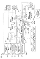
図11に参照される創造的なシステムを実装するための例示的なシステムは、コンピュータ310の形式として、汎用コンピューティングデバイスを含む。コンピュータ310のコンポーネントには、プロセッシングユニット320、システムメモリ330、及び、システムメモリを含む様々なシステムコンポーネントをプロセッシングユニット320に接続するシステムバス321を含むが、それらに限られるものではない。システムバス321には、様々なバスアーキテクチャを採用したローカルバス、周辺バス、メモリコントローラ、メモリバスを含む、様々なタイプのバス構造を採用し得る。例として、そのようなアーキテクチャには、工業規格アーキテクチャ(ISA)バス、マイクロチャネルアーキテクチャ(MCA)バス、エンハンスドISA(EISA)バス、ビデオエレクトロニクススタンダードアソシエーション(VESA)ローカルバス、及び、メザニンバスとして知られているペリフェラルコンポーネントインターコネクト(PCI)バス、を含むが、それらに限定されるものではない。
An exemplary system for implementing the creative system referenced in FIG. 11 includes a general purpose computing device in the form of a
コンピュータ310は、様々なコンピュータ読取可能な媒体を含む。コンピュータ読取可能媒体は、コンピュータ310がアクセス可能ないかなる有用な媒体であってもよく、揮発性あるいは不揮発性媒体、着脱可能あるいは着脱不可媒体のいずれであってもよい。例として、コンピュータ読取可能媒体は、コンピュータストレージ媒体や通信媒体を備えるものであってもよいが、それらに限定されるものではない。コンピュータストレージ媒体は、揮発性あるいは不揮発性、着脱可能あるいは着脱不可の媒体のいずれであってもよく、それらは、コンピュータ読取可能な命令、データ構造、プログラムモジュール、あるいは他のデータなどの情報記憶に関する如何なる方法あるいは技術によって実装されてもよい。コンピュータストレージ媒体には、ランダムアクセスメモリ(RAM)、リードオンリイメモリ(ROM)、EEPROM、フラッシュメモリ、他のメモリテクノロジ、CD−ROM、デシタル多用途ディスク(DVD)、あるいは他の光学ディスク媒体、磁気カセット、磁気テープ、磁気ディスク装置、あるいは他の磁気記憶デバイス、あるいは、情報を記憶することができ、コンピュータ310からアクセス可能な他の媒体が含まれるがそれらに限定されるものではない。通信媒体には、典型的には、コンピュータ読取可能な命令、データ構造体、プログラムモジュールや、キャリアウエーブや他の転送機構による変調データ信号による他のデータがあり、さらにはいかなる情報配信媒体も含む。「変調データ信号」は、情報を信号に符号化する方式であり、1以上の特性の組あるいは変化を含む信号を意味する。例として、通信媒体には、有線ネットワークや直接ワイヤ接続などの有線媒体、音波、RF、赤外線などの無線媒体、あるいは他の無線媒体が含まれるがそれらに限定されるものではない。上記した媒体のいかなる組み合わせも、コンピュータ読取可能媒体の範囲に含まれる。
システムメモリ330は、ROM331やRAM332のような揮発性や不揮発性のメモリの形態のコンピュータ記憶媒体を含む。スタートアップの際などにコンピュータ310内の要素間での情報の転送を補助する基本的なルーチンを含むベーシック入力/出力システム(BIOS)333は、典型的にはROM331に記憶されている。RAM332は、典型的には、プロセッシングユニット320上で実行される、及び/又は、直ちにアクセスし得るデータ及び/又はプログラムモジュールを含む。例として、図11には、オペレーティングシステム334、アプリケーションプログラム335、他のプログラムモジュール336、及び、プログラムデータ337が示されているが、それらに限られるものではない。
The
コンピュータ310は、また、他の着脱式/着脱不可の、揮発性/不揮発性のコンピュータ記憶媒体を含む。例として、図11には、着脱不可の不揮発性磁気媒体にデータを書き込むあるいはデータを読み出すハードディスクドライブ341、着脱式の不揮発性磁気ディスク352にデータを書き込むあるいはデータを読み出す磁気ディスクドライブ351が示されている。コンピュータ310は、光学媒体にデータを書き込む/データを読み出す光学媒体読取りデバイス355を含むこともある。
The
この例示的なコンピュータ環境において用いられる他の着脱式/着脱不可、揮発性/不揮発性のコンピュータ記憶媒体には、磁気テープカセット、フラッシュメモリカード、DVD、デシタルビデオテープ、ソリッドステートRAM、ソリッドステートROM、等々が含まれ得るが、それらに限られるものではない。ハードディスク341は、典型的には、インタフェイス340などの着脱不可のメモリインタフェイスを介してシステムバス321に接続されており、磁気ディスクドライブ351と光学媒体読み取りデバイス355は、典型的には、インタフェイス350などの着脱式メモリインタフェイスによってシステムバス321に接続されている。
Other removable / non-removable, volatile / nonvolatile computer storage media used in this exemplary computer environment include magnetic tape cassette, flash memory card, DVD, digital video tape, solid state RAM, solid state ROM , And the like, but are not limited to. The
図11に示されており上記で説明したドライブとそれに関連するコンピュータ記憶媒体は、コンピュータ310のためのコンピュータ読取り可能な命令、データ構造体、プログラムモジュール、及び、他のデータの格納場所を提供する。例えば、図11において、ハードディスク341は、オペレーティングシステム344、アプリケーションプログラム345、他のプログラムモジュール346、及び、プログラムデータ347を記憶するものとして描かれている。それらのコンポーネントは、オペレーティングシステム334、アプリケーションプログラム335、他のプログラムモジュール336、及び、プログラムデータ337と異なっていてもよいし同じであってもよい。オペレーティングシステム344、アプリケーションプログラム345、他のプログラムモジュール346、及び、プログラムデータ347には、図に描かれるのに異なる番号が与えられており、それらは少なくとも異なるコピーである。ユーザは、キーボード362、通常マウスと呼ばれるポインティングデバイス361、トラックボールやタッチパッドなどの入力デバイスを介して命令や情報をコンピュータ310に入力する。他の入力デバイス(不図示)として、マイクロホン、ジョイスティック、ゲームパッド、サテライトディッシュ、スキャナなどがある。それらの、あるいは他の入力デバイスは、システムバス321に接続しているユーザ入力インタフェイス360を介してプロセッシングユニット320に接続されているが、パラレルポート、ゲームポート、あるいは、ユニバーサルシリアルバス(USB)などの他のインタフェイスやバス構造を介して接続されるものであってもよい。モニタ391や他のタイプのディスプレイデバイスもまた、ビデオインタフェイス390などのインタフェイスを介してシステムバス321に接続されている。モニタに加えてコンピュータは、スピーカ397やプリンタ396などの他の周辺出力デバイスを含んでおり、それらは、出力周辺インタフェイス395を介して接続されている。
The drives and associated computer storage media shown in FIG. 11 and described above provide computer readable instructions, data structures, program modules, and other data storage locations for
コンピュータ310は、リモートコンピュータ380のような、1つあるいはそれ以上のリモートコンピュータとの論理的な接続を使ったネットワーク環境にて動作するものであってもよい。リモートコンピュータ380は、パーソナルコンピュータ、サーバ、ルータ、ネットワークPC、ピアデバイス、あるいは、他の一般的なネットワークノードであってよく、典型的には、図11ではメモリ記憶デバイス381しか描かれていないが、コンピュータ310のように上記説明した要素の多くあるいは全てを含んでいてよい。図11に示した論理的な接続には、ローカルエリアネットワーク(LAN)371と広域ネットワーク(WAN)373が含まれるが、他のネットワークを含んでもよい。そのようなネットワーク環境には、オフィスにて一般的である、エンタープライズワイドコンピュータネットワーク、イントラネット、及び、インターネットがある。
LANネットワーク環境を使う場合は、コンピュータ310は、ネットワークインタフェイスあるいはアダプタ370を介してLAN371に接続される。WANネットワーク環境を使う場合は、コンピュータ310は、典型的には、モデム372や、インターネットのようなWAN373との通信を確立するための他の手段を有する。内線あるいは外線のモデム372は、ユーザ入力インタフェイス360や他の適切なメカニズムを介してシステムバス321に接続される。ネットワーク環境においては、コンピュータ310に描かれているプログラムモジュール、あるいはその一部は、リモート記憶デバイスに記憶されていてもよい。例として、図11には、メモリデバイス381に格納されているリモートアプリケーションプログラム385が描かれているが、これに限定されるものではない。図に示しているネットワーク接続は一例であって、コンピュータ間の通信リンクを確立する他の手段を用いてもよい。
When using a LAN network environment, the
いくつかの実施形態では、トランザクションマネジメントシステムの一部あるいは全ては、ソフトウエアとして実装されてよい。そのソフトウエアは、1つあるいは複数のプロセッサ読取り可能な記憶デバイスに格納され、1つあるいは複数のプロセッサをプログラムするのに用いられる。図10に戻り、エンタープライズマネージャ220は、さらに、エンコードエンジン230とデコードエンジン232を有するCODECを備える。エンコードエンジン230とデコードエンジン232は、エンタープライズマネージャ220と送受信されるデータ、あるいは、エンタープライズマネージャに記憶されているデータに対して上記した高次圧縮技法を実行する。エンジン230と232を含むCODECは、管理対象のアプリケーション200、ワークステーション224、226、及び/又は、データベース222を搭載する1つあるいは複数のコンピュータシステムに代替的にあるいは付加的に備えられていてもよく、その場合、それらのコンピュータシステムに記憶されるデータあるいは送受信されるデータを符号化する。
In some embodiments, some or all of the transaction management system may be implemented as software. The software is stored in one or more processor readable storage devices and is used to program one or more processors. Returning to FIG. 10, the
一般に、エンコードエンジン232は、コンポーネント200、220、222、224、及び、226のいずれかに備えられた記憶媒体から整数値を受け取り、その値をエンコードし、エンコードした値を、コンポーネント200、220、222、224、及び、226の1つあるいは複数の記憶媒体に記憶する。一実施形態では、エンコードエンジン232は、エンコードされた値を出力し、それらの値を格納するために新たなファイル及び/又はデータ構造体が作成される。同様に、デコードエンジンは、コンポーネント200、220、222、224、及び、226のいずれかに備えられた記憶媒体からエンコードされた値を受け取り、それらの値をデコードし、コンポーネント200、220、222、224、及び、226の1つあるいは複数に、デコードした値を出力する(表示することを含む)。一実施形態では、デコードエンジン232は、整数値を出力し、それらの値を記憶媒体に格納する、及び/又は出力するために新たなファイル及び/又はデータ構造体が作成される。
In general, the encoding engine 232 receives an integer value from a storage medium provided in any of the
一実施形態では、図11のシステムのユーザは、閾値追跡時間を指定することによって、エンタプライズマネージャに管理されているエージェントの全てあるいは幾つかについてトランザクション追跡を起動することができる。エージェント内のトランザクションでありその実行時間がその閾値レベルを超えてしまった全てのトランザクションは、追跡され、エンタープライズマネージャ220に報告される。エンタープライズマネージャ220は、追跡情報の要求を登録した適切なワークステーションにその情報を配信する。ワークステーションは、閾値を超えた全てのトランザクションをリストアップするGUIを備えている。リストアップされたトランザクションの夫々に対して、追跡されたトランザクションにおいてどこで時間が費やされているかをユーザが直ちに理解できるように可視化が行われる。
In one embodiment, the user of the system of FIG. 11 can initiate transaction tracking for all or some of the agents managed by the enterprise manager by specifying a threshold tracking time. All transactions within an agent whose execution time has exceeded the threshold level are tracked and reported to the
以上、以上、本発明の具体例を詳細に説明したが、これらは例示に過ぎず、本発明の範囲を限定するものではない。上記した技術には、以上に例示した具体例を様々に変形、変更したものが含まれる。上記した実施形態は、本発明の原理をベストに説明するために選定されたものであり、その実用に際しては、本発明が最適にその有用性を発揮するように、その特定用途に適するように当業者が様々に変形し得る。本発明の範囲は、以下に記載した特許請求の範囲によって定義される。 As mentioned above, although the specific example of this invention was demonstrated in detail, these are only illustrations and do not limit the scope of the present invention. The above-described techniques include various modifications and changes of the specific examples illustrated above. The above-described embodiment is selected to best explain the principle of the present invention, and in practical use, the present invention is suitable for the specific application so that the utility is optimally exhibited. Various modifications can be made by those skilled in the art. The scope of the invention is defined by the claims set forth below.
Claims (12)
a)前記整数値のバイナリ表記における桁数Nを決定するステップ;
b)Nのバイナリ表記における桁数N’を決定するステップ;
c)次の要素を有するように前記整数値をエンコードするステップ;
1)N’−1個のゼロに等しい第1要素;
2)第1要素に付け加えられる第2要素であり、前記整数値のバイナリ表記から最上位ビットを除いた値に等しい第2要素;
d)エンコードされた値を出力するステップ;
を備える方法。 An integer value used in a software application, wherein the binary representation of the integer value encodes an integer value having a number of digits equal to the maximum number of binary digits handled in the software application ;
a) determining the number N of digits in the binary representation of the integer value;
b) determining the number N ′ of digits in the binary representation of N;
c) encoding the integer value to have the following elements;
1) N′−1 first element equal to zero;
2) a second element added to the first element, the second element equal to a value obtained by removing the most significant bit from the binary representation of the integer value;
d) outputting the encoded value;
A method comprising:
をさらに備える請求項1から7のいずれか1項に記載の方法。 (E) By shifting at least a part of the integer value to a higher or lower position by a predetermined constant, the integer area in the data system and the number of digits in the binary representation is the upper limit of the maximum number of digits. Normalizing step;
The method according to any one of claims 1 to 7, further comprising:
当該システムは、モニタリングソフトウエアアプリケーションと、当該モニタリングソフトウエアアプリケーションによってモニタされるモニタ対象ソフトウエアアプリケーションを含んでおり、
当該モニタ対象とモニタリングソフトウエアアプリケーションは、一つのコンピュータデバイス内の1つのプロセッサ上で動作するものであり、
前記1つのプロセッサは、前記モニタリングシステム内で用いられる整数値であって、その整数値のバイナリ表現が、前記モニタリングソフトウエアアプリケーションにて扱われるバイナリ数の最大桁数に等しい桁数を有する整数値をエンコードする当該方法を実行するものであり、
当該方法が、
a)前記整数値のバイナリ表記における桁数Nを決定するステップ;
b)Nのバイナリ表記における桁数N’を決定するステップ;
c)次の要素を有するように前記整数値をエンコードするステップ;
1)N’−1個のゼロに等しい第1要素;
2)第1要素に付け加えられる第2要素であり、前記整数値のバイナリ表記から最上位ビットを除いたものに等しい第2要素;
d)エンコードされた値を出力するステップ;
を備えるエンコード方法。 An integer encoding method executed in a monitoring system for detecting and diagnosing web application and website performance problems ,
The system includes a monitoring software application and a monitored software application monitored by the monitoring software application.
The monitored and monitoring software application, which operates on a single processor in a computing device,
Said one processor, an integer value used in the monitoring system, the binary representation of the integer value, an integer value having a number of digits equal to the maximum number of digits number of binary handled by the monitoring software application To perform this method of encoding
This method comprising the steps of:
a) determining the number N of digits in the binary representation of the integer value;
b) determining the number N ′ of digits in the binary representation of N;
c) encoding the integer value to have the following elements;
1) N′−1 first element equal to zero;
2) a second element added to the first element, equal to the binary representation of the integer value minus the most significant bit;
d) outputting the encoded value;
An encoding method comprising:
e)エンコードされた値の先頭のゼロの個数を決定するステップ;
f)先頭のゼロの個数が、前記データシステムの前記最大整数値の前記最大バイナリ桁数のlog2 の値以上であるか否かを決定するステップ;
g)前記ステップ(e)にて、前記先頭のゼロの個数が、前記データシステムの前記最大整数値の前記最大バイナリ桁数のlog2 の値以上であると決定された場合、2N-1に等しい第1中間十進数Jを決定するステップ、ただし、Nは、前記最大整数値の前記最大バイナリ桁数に等しい値である;
h)エンコードされた値からその最上位ビットを除いた値の十進数変換値に等しい値Kであって第2中間十進数Kを決定するステップ;
i)第1中間十進数Jを第2中間十進数Kに加え、エンコードされた値によって示される整数値を提供するステップ;
を備える請求項9に記載の方法。 Said one processor, which executes a method for decoding the encoded value by d) from the step a), a method for the decoding,
e) determining the number of leading zeros in the encoded value;
f) determining whether the number of leading zeros is greater than or equal to the log 2 value of the maximum binary digits of the maximum integer value of the data system;
g) If it is determined in step ( e ) that the number of leading zeros is greater than or equal to the log 2 value of the maximum binary digits of the maximum integer value of the data system, 2 N-1 Determining a first intermediate decimal number J equal to, where N is a value equal to the maximum number of binary digits of the maximum integer value;
h) determining a second intermediate decimal number K that is equal to the decimal conversion value of the encoded value minus its most significant bit;
i) adding the first intermediate decimal number J to the second intermediate decimal number K to provide an integer value indicated by the encoded value;
The method of claim 9 comprising:
j)エンコードされた値の中から前記先頭のゼロに続くN’ビットを読み出すステップ;ここで、N’は前記先頭のゼロの個数に1を加えた値であってNのバイナリ表記の桁数に等しい値である;
k)読み出したN’ビットの十進数変換値に等しい値Nを決定するステップ;
l)前記ステップh)で決定された値Nを用いて、J=2N-1の式によって値Jを決定するステップ;
を備える請求項9又は10に記載の方法。 When the number of leading zeros is less than the value of log 2 of the maximum binary digits of the maximum integer value of the data system, the following steps:
j) reading N ′ bits following the leading zero from the encoded value; where N ′ is a value obtained by adding 1 to the number of leading zeros and the number of digits in the binary representation of N A value equal to
k) determining a value N equal to the read N′-bit decimal conversion value;
l) using the value N determined in step h) to determine the value J according to the formula J = 2 N−1 ;
The method according to claim 9 or 10 .
(m)前記整数値の少なくとも一部を既定の定数分だけ上位又は下位へシフトすることによって、モニタリングシステムによって使われている整数域であってバイナリ表現における桁数が前記最大桁数を上限とする整数域を正規化するステップ;
を備える方法。 12. The method according to any one of claims 9 to 11 , further comprising:
(M) By shifting at least a part of the integer value to a higher or lower position by a predetermined constant, the integer range used by the monitoring system and the number of digits in the binary representation is limited to the maximum number of digits. Normalizing the integer range to do;
A method comprising:
Applications Claiming Priority (2)
| Application Number | Priority Date | Filing Date | Title |
|---|---|---|---|
| US12/707,582 US8977664B2 (en) | 2010-02-17 | 2010-02-17 | System for storing and transmitting compressed integer data |
| US12/707582 | 2010-02-17 |
Publications (2)
| Publication Number | Publication Date |
|---|---|
| JP2011193451A JP2011193451A (en) | 2011-09-29 |
| JP5079110B2 true JP5079110B2 (en) | 2012-11-21 |
Family
ID=44202506
Family Applications (1)
| Application Number | Title | Priority Date | Filing Date |
|---|---|---|---|
| JP2011030873A Expired - Fee Related JP5079110B2 (en) | 2010-02-17 | 2011-02-16 | System for storing and transferring compressed integer data |
Country Status (4)
| Country | Link |
|---|---|
| US (1) | US8977664B2 (en) |
| EP (1) | EP2365635A1 (en) |
| JP (1) | JP5079110B2 (en) |
| KR (1) | KR101166910B1 (en) |
Families Citing this family (8)
| Publication number | Priority date | Publication date | Assignee | Title |
|---|---|---|---|---|
| KR101006059B1 (en) * | 2010-07-16 | 2011-01-07 | 오재원 | Information Compression Method |
| US9754384B2 (en) * | 2012-04-18 | 2017-09-05 | Suzhou Superengine Graphics Software Technology Development Co., Ltd. | Relevant method and device for compression, decompression and progressive transmission of spatial data |
| JP6772486B2 (en) * | 2016-03-08 | 2020-10-21 | 日本電気株式会社 | Sensor data processing device, sensor data processing system, sensor data processing method, and sensor data processing program |
| US11290710B1 (en) * | 2020-11-30 | 2022-03-29 | Amazon Technologies, Inc. | Adaptable golomb coding |
| US11995871B1 (en) | 2020-11-30 | 2024-05-28 | Amazon Technologies, Inc. | Lossy block repair |
| US11967118B1 (en) | 2020-11-30 | 2024-04-23 | Amazon Technologies, Inc. | Hybrid codec |
| US12530331B2 (en) | 2024-05-30 | 2026-01-20 | International Business Machines Corporation | Decompressing human readable prime number compression (HRPNC) objects using metadata |
| US12561202B2 (en) | 2024-05-30 | 2026-02-24 | International Business Machines Corporation | Enforced checksums for human readable prime number compression (HRPNC) |
Family Cites Families (5)
| Publication number | Priority date | Publication date | Assignee | Title |
|---|---|---|---|---|
| JP3368157B2 (en) * | 1996-11-18 | 2003-01-20 | キヤノン株式会社 | Data compression apparatus, method and system |
| JPH1188189A (en) | 1997-09-10 | 1999-03-30 | Canon Inc | Data compression processing method and apparatus, and computer readable memory |
| US6260187B1 (en) | 1998-08-20 | 2001-07-10 | Wily Technology, Inc. | System for modifying object oriented code |
| US8321485B2 (en) * | 2006-11-08 | 2012-11-27 | Hitachi, Ltd. | Device and method for constructing inverted indexes |
| US7924178B2 (en) * | 2008-10-01 | 2011-04-12 | Seagate Technology Llc | System and method for lossless data compression |
-
2010
- 2010-02-17 US US12/707,582 patent/US8977664B2/en not_active Expired - Fee Related
-
2011
- 2011-02-16 JP JP2011030873A patent/JP5079110B2/en not_active Expired - Fee Related
- 2011-02-17 KR KR1020110014183A patent/KR101166910B1/en not_active Expired - Fee Related
- 2011-02-17 EP EP11250188A patent/EP2365635A1/en not_active Ceased
Also Published As
| Publication number | Publication date |
|---|---|
| KR20110095209A (en) | 2011-08-24 |
| EP2365635A1 (en) | 2011-09-14 |
| KR101166910B1 (en) | 2012-07-23 |
| US8977664B2 (en) | 2015-03-10 |
| US20110202584A1 (en) | 2011-08-18 |
| JP2011193451A (en) | 2011-09-29 |
Similar Documents
| Publication | Publication Date | Title |
|---|---|---|
| JP5079110B2 (en) | System for storing and transferring compressed integer data | |
| CN108988866B (en) | Efficient data compression and analysis as a service | |
| JP6242074B2 (en) | Method and apparatus for signal data compression and decompression (signal data compression and decompression) | |
| Liang et al. | Significantly improving lossy compression quality based on an optimized hybrid prediction model | |
| US9088540B1 (en) | Processing data formatted for efficient communication over a network | |
| US10666289B1 (en) | Data compression using dictionary encoding | |
| CN110019865B (en) | Mass image processing method and device, electronic equipment and storage medium | |
| CN114065704A (en) | Data compression method, electronic device and computer program product | |
| JP6048251B2 (en) | Data compression device, data compression method, data compression program, data restoration device, data restoration method, and data restoration program | |
| CN116208168A (en) | A data compression method, data decompression method and device | |
| US20240421830A1 (en) | Unified platform for multi-type data compression and decompression using homomorphic encryption and neural upsampling | |
| US20150181236A1 (en) | Transform space difference compression | |
| US20100039300A1 (en) | Lzw data compression algorithm | |
| US12425045B2 (en) | Computer data compression utilizing multiple symbol alphabets and dynamic binding of symbol alphabets | |
| CN112054805B (en) | Model data compression method, system and related equipment | |
| US11438009B2 (en) | Encoding apparatus, decoding apparatus, data structure of code sequence, encoding method, decoding method, encoding program, and decoding program | |
| US9059729B1 (en) | Statistical compressibility determination system and method | |
| CN107797898B (en) | Data acquisition method and device thereof | |
| CN109474826B (en) | Image compression method, device, electronic device and storage medium | |
| WO2007100307A1 (en) | Streaming repetition coded compression | |
| CN110289935B (en) | Decoding method, device, terminal and storage medium | |
| US20100023479A1 (en) | Hexadecimal file fast decompression method | |
| CN112486976A (en) | Data processing method, device, network equipment and storage medium | |
| US12164768B2 (en) | Medical imaging data compression utilizing codebooks | |
| US20220393699A1 (en) | Method for compressing sequential records of interrelated data fields |
Legal Events
| Date | Code | Title | Description |
|---|---|---|---|
| A977 | Report on retrieval |
Free format text: JAPANESE INTERMEDIATE CODE: A971007 Effective date: 20120210 |
|
| A131 | Notification of reasons for refusal |
Free format text: JAPANESE INTERMEDIATE CODE: A131 Effective date: 20120221 |
|
| A521 | Written amendment |
Free format text: JAPANESE INTERMEDIATE CODE: A523 Effective date: 20120511 |
|
| TRDD | Decision of grant or rejection written | ||
| A01 | Written decision to grant a patent or to grant a registration (utility model) |
Free format text: JAPANESE INTERMEDIATE CODE: A01 Effective date: 20120731 |
|
| A01 | Written decision to grant a patent or to grant a registration (utility model) |
Free format text: JAPANESE INTERMEDIATE CODE: A01 |
|
| A61 | First payment of annual fees (during grant procedure) |
Free format text: JAPANESE INTERMEDIATE CODE: A61 Effective date: 20120828 |
|
| FPAY | Renewal fee payment (event date is renewal date of database) |
Free format text: PAYMENT UNTIL: 20150907 Year of fee payment: 3 |
|
| R150 | Certificate of patent or registration of utility model |
Ref document number: 5079110 Country of ref document: JP Free format text: JAPANESE INTERMEDIATE CODE: R150 Free format text: JAPANESE INTERMEDIATE CODE: R150 |
|
| FPAY | Renewal fee payment (event date is renewal date of database) |
Free format text: PAYMENT UNTIL: 20150907 Year of fee payment: 3 |
|
| S111 | Request for change of ownership or part of ownership |
Free format text: JAPANESE INTERMEDIATE CODE: R313111 |
|
| FPAY | Renewal fee payment (event date is renewal date of database) |
Free format text: PAYMENT UNTIL: 20150907 Year of fee payment: 3 |
|
| R350 | Written notification of registration of transfer |
Free format text: JAPANESE INTERMEDIATE CODE: R350 |
|
| R250 | Receipt of annual fees |
Free format text: JAPANESE INTERMEDIATE CODE: R250 |
|
| R250 | Receipt of annual fees |
Free format text: JAPANESE INTERMEDIATE CODE: R250 |
|
| R250 | Receipt of annual fees |
Free format text: JAPANESE INTERMEDIATE CODE: R250 |
|
| R250 | Receipt of annual fees |
Free format text: JAPANESE INTERMEDIATE CODE: R250 |
|
| LAPS | Cancellation because of no payment of annual fees |