JP5078984B2 - Carton with dispenser - Google Patents
Carton with dispenser Download PDFInfo
- Publication number
- JP5078984B2 JP5078984B2 JP2009500430A JP2009500430A JP5078984B2 JP 5078984 B2 JP5078984 B2 JP 5078984B2 JP 2009500430 A JP2009500430 A JP 2009500430A JP 2009500430 A JP2009500430 A JP 2009500430A JP 5078984 B2 JP5078984 B2 JP 5078984B2
- Authority
- JP
- Japan
- Prior art keywords
- panel
- carton
- dispenser
- panels
- access
- Prior art date
- Legal status (The legal status is an assumption and is not a legal conclusion. Google has not performed a legal analysis and makes no representation as to the accuracy of the status listed.)
- Expired - Fee Related
Links
- 238000000034 method Methods 0.000 claims description 14
- 238000000926 separation method Methods 0.000 claims 2
- 239000000463 material Substances 0.000 description 11
- 230000003313 weakening effect Effects 0.000 description 6
- 239000000853 adhesive Substances 0.000 description 4
- 230000001070 adhesive effect Effects 0.000 description 4
- 238000012986 modification Methods 0.000 description 4
- 230000004048 modification Effects 0.000 description 4
- 238000005096 rolling process Methods 0.000 description 3
- 235000013361 beverage Nutrition 0.000 description 2
- 239000004927 clay Substances 0.000 description 2
- 239000011248 coating agent Substances 0.000 description 2
- 238000000576 coating method Methods 0.000 description 2
- 230000000670 limiting effect Effects 0.000 description 2
- 239000000123 paper Substances 0.000 description 2
- 239000011087 paperboard Substances 0.000 description 2
- 238000005452 bending Methods 0.000 description 1
- 239000011111 cardboard Substances 0.000 description 1
- 235000013305 food Nutrition 0.000 description 1
- 239000003292 glue Substances 0.000 description 1
- 238000007373 indentation Methods 0.000 description 1
- 230000014759 maintenance of location Effects 0.000 description 1
- 235000021485 packed food Nutrition 0.000 description 1
- 230000036961 partial effect Effects 0.000 description 1
- 238000003825 pressing Methods 0.000 description 1
- 239000011241 protective layer Substances 0.000 description 1
- 230000002829 reductive effect Effects 0.000 description 1
- 238000006467 substitution reaction Methods 0.000 description 1
Images


Classifications
-
- B—PERFORMING OPERATIONS; TRANSPORTING
- B65—CONVEYING; PACKING; STORING; HANDLING THIN OR FILAMENTARY MATERIAL
- B65D—CONTAINERS FOR STORAGE OR TRANSPORT OF ARTICLES OR MATERIALS, e.g. BAGS, BARRELS, BOTTLES, BOXES, CANS, CARTONS, CRATES, DRUMS, JARS, TANKS, HOPPERS, FORWARDING CONTAINERS; ACCESSORIES, CLOSURES, OR FITTINGS THEREFOR; PACKAGING ELEMENTS; PACKAGES
- B65D71/00—Bundles of articles held together by packaging elements for convenience of storage or transport, e.g. portable segregating carrier for plural receptacles such as beer cans or pop bottles; Bales of material
- B65D71/06—Packaging elements holding or encircling completely or almost completely the bundle of articles, e.g. wrappers
- B65D71/12—Packaging elements holding or encircling completely or almost completely the bundle of articles, e.g. wrappers the packaging elements, e.g. wrappers being formed by folding a single blank
- B65D71/36—Packaging elements holding or encircling completely or almost completely the bundle of articles, e.g. wrappers the packaging elements, e.g. wrappers being formed by folding a single blank having a tubular shape, e.g. tubular wrappers, with end walls
-
- B—PERFORMING OPERATIONS; TRANSPORTING
- B65—CONVEYING; PACKING; STORING; HANDLING THIN OR FILAMENTARY MATERIAL
- B65D—CONTAINERS FOR STORAGE OR TRANSPORT OF ARTICLES OR MATERIALS, e.g. BAGS, BARRELS, BOTTLES, BOXES, CANS, CARTONS, CRATES, DRUMS, JARS, TANKS, HOPPERS, FORWARDING CONTAINERS; ACCESSORIES, CLOSURES, OR FITTINGS THEREFOR; PACKAGING ELEMENTS; PACKAGES
- B65D2571/00—Bundles of articles held together by packaging elements for convenience of storage or transport, e.g. portable segregating carrier for plural receptacles such as beer cans, pop bottles; Bales of material
- B65D2571/00123—Bundling wrappers or trays
- B65D2571/00129—Wrapper locking means
- B65D2571/00135—Wrapper locking means integral with the wrapper
- B65D2571/00141—Wrapper locking means integral with the wrapper glued
-
- B—PERFORMING OPERATIONS; TRANSPORTING
- B65—CONVEYING; PACKING; STORING; HANDLING THIN OR FILAMENTARY MATERIAL
- B65D—CONTAINERS FOR STORAGE OR TRANSPORT OF ARTICLES OR MATERIALS, e.g. BAGS, BARRELS, BOTTLES, BOXES, CANS, CARTONS, CRATES, DRUMS, JARS, TANKS, HOPPERS, FORWARDING CONTAINERS; ACCESSORIES, CLOSURES, OR FITTINGS THEREFOR; PACKAGING ELEMENTS; PACKAGES
- B65D2571/00—Bundles of articles held together by packaging elements for convenience of storage or transport, e.g. portable segregating carrier for plural receptacles such as beer cans, pop bottles; Bales of material
- B65D2571/00123—Bundling wrappers or trays
- B65D2571/00432—Handles or suspending means
- B65D2571/00456—Handles or suspending means integral with the wrapper
- B65D2571/00462—Straps made by two slits in a wall
-
- B—PERFORMING OPERATIONS; TRANSPORTING
- B65—CONVEYING; PACKING; STORING; HANDLING THIN OR FILAMENTARY MATERIAL
- B65D—CONTAINERS FOR STORAGE OR TRANSPORT OF ARTICLES OR MATERIALS, e.g. BAGS, BARRELS, BOTTLES, BOXES, CANS, CARTONS, CRATES, DRUMS, JARS, TANKS, HOPPERS, FORWARDING CONTAINERS; ACCESSORIES, CLOSURES, OR FITTINGS THEREFOR; PACKAGING ELEMENTS; PACKAGES
- B65D2571/00—Bundles of articles held together by packaging elements for convenience of storage or transport, e.g. portable segregating carrier for plural receptacles such as beer cans, pop bottles; Bales of material
- B65D2571/00123—Bundling wrappers or trays
- B65D2571/00432—Handles or suspending means
- B65D2571/00456—Handles or suspending means integral with the wrapper
- B65D2571/00469—Straps made between two handholes
-
- B—PERFORMING OPERATIONS; TRANSPORTING
- B65—CONVEYING; PACKING; STORING; HANDLING THIN OR FILAMENTARY MATERIAL
- B65D—CONTAINERS FOR STORAGE OR TRANSPORT OF ARTICLES OR MATERIALS, e.g. BAGS, BARRELS, BOTTLES, BOXES, CANS, CARTONS, CRATES, DRUMS, JARS, TANKS, HOPPERS, FORWARDING CONTAINERS; ACCESSORIES, CLOSURES, OR FITTINGS THEREFOR; PACKAGING ELEMENTS; PACKAGES
- B65D2571/00—Bundles of articles held together by packaging elements for convenience of storage or transport, e.g. portable segregating carrier for plural receptacles such as beer cans, pop bottles; Bales of material
- B65D2571/00123—Bundling wrappers or trays
- B65D2571/00555—Wrapper opening devices
- B65D2571/00561—Lines of weakness
- B65D2571/00574—Lines of weakness whereby contents can still be carried after the line has been torn
- B65D2571/0058—The tear line defining a dispensing aperture provided with means for preventing the articles from freely exiting the wrapper, e.g. by rolling out
- B65D2571/00586—The tear line defining a dispensing aperture provided with means for preventing the articles from freely exiting the wrapper, e.g. by rolling out the means being elastically deformed for removing an object
-
- B—PERFORMING OPERATIONS; TRANSPORTING
- B65—CONVEYING; PACKING; STORING; HANDLING THIN OR FILAMENTARY MATERIAL
- B65D—CONTAINERS FOR STORAGE OR TRANSPORT OF ARTICLES OR MATERIALS, e.g. BAGS, BARRELS, BOTTLES, BOXES, CANS, CARTONS, CRATES, DRUMS, JARS, TANKS, HOPPERS, FORWARDING CONTAINERS; ACCESSORIES, CLOSURES, OR FITTINGS THEREFOR; PACKAGING ELEMENTS; PACKAGES
- B65D2571/00—Bundles of articles held together by packaging elements for convenience of storage or transport, e.g. portable segregating carrier for plural receptacles such as beer cans, pop bottles; Bales of material
- B65D2571/00123—Bundling wrappers or trays
- B65D2571/00648—Elements used to form the wrapper
- B65D2571/00654—Blanks
- B65D2571/0066—Blanks formed from one single sheet
-
- B—PERFORMING OPERATIONS; TRANSPORTING
- B65—CONVEYING; PACKING; STORING; HANDLING THIN OR FILAMENTARY MATERIAL
- B65D—CONTAINERS FOR STORAGE OR TRANSPORT OF ARTICLES OR MATERIALS, e.g. BAGS, BARRELS, BOTTLES, BOXES, CANS, CARTONS, CRATES, DRUMS, JARS, TANKS, HOPPERS, FORWARDING CONTAINERS; ACCESSORIES, CLOSURES, OR FITTINGS THEREFOR; PACKAGING ELEMENTS; PACKAGES
- B65D2571/00—Bundles of articles held together by packaging elements for convenience of storage or transport, e.g. portable segregating carrier for plural receptacles such as beer cans, pop bottles; Bales of material
- B65D2571/00123—Bundling wrappers or trays
- B65D2571/00709—Shape of the formed wrapper, i.e. shape of each formed element if the wrapper is made from more than one element
- B65D2571/00722—Shape of the formed wrapper, i.e. shape of each formed element if the wrapper is made from more than one element tubular with end walls, e.g. walls not extending on the whole end surface
- B65D2571/00728—Shape of the formed wrapper, i.e. shape of each formed element if the wrapper is made from more than one element tubular with end walls, e.g. walls not extending on the whole end surface the end walls being closed by gluing
Landscapes
- Engineering & Computer Science (AREA)
- Mechanical Engineering (AREA)
- Cartons (AREA)
- Apparatus For Radiation Diagnosis (AREA)
- Analysing Materials By The Use Of Radiation (AREA)
Abstract
Description
本発明は、概して、円筒形の容器またはその他の種類の品物を保持し、取り出すためのカートンに関する。 The present invention relates generally to cartons for holding and removing cylindrical containers or other types of items.
[関連出願の記述]
本出願は、2006年3月13日付申請の米国仮特許出願第60/781,871の優先権を主張する。上記参照の仮出願の全体は、全体として本願に提示されるように、引用により組み込まれる。
[Description of related application]
This application claims priority to US Provisional Patent Application No. 60 / 781,871, filed March 13, 2006. The entirety of the above-referenced provisional application is incorporated by reference as it is presented herein in its entirety.
1回に1つの容器を取り出すためのディスペンサを有する、容器の運搬が可能な完全に囲まれたカートンは、過去に、使用されてきた。ディスペンサパネルを掴み、カートンから取り外すために、ディスペンサ上に開口またはタブを含む、カートンの多様な場所に取り外し可能なディスペンサパネルを備えたディスペンサが提供されてきた。容易に掴み、カートンから取り外すことができるディスペンサパネル付きのカートンを提供することが望ましい。 Fully enclosed cartons capable of transporting containers with dispensers for removing one container at a time have been used in the past. Dispensers have been provided with removable dispenser panels at various locations in the carton, including openings or tabs on the dispenser, for grasping and removing the dispenser panel from the carton. It would be desirable to provide a carton with a dispenser panel that can be easily grasped and removed from the carton.
概して、本発明の一態様は、複数の容器を保持するためのカートンに関する。カートンは、複数の品物を収容するためのカートンを備える。カートンは、カートンの内部周辺に少なくとも部分的に延在する複数のパネルを備える。複数のパネルは、トップパネルと、ボトムパネルと、第1のサイドパネルと、第2のサイドパネルと、を備える。少なくとも2つの端部フラップは、複数のパネルのそれぞれのパネルにそれぞれ折り曲げ可能に取り付けられる。端部フラップは、互いに重なり合うことによって、カートンの端部を少なくとも部分的に閉じる。ディスペンサによって、カートンから品物を取り出すことができる。ディスペンサは、カートンの切取線によって少なくとも部分的に画定され、ディスペンサ開口を少なくともさらに開くために、少なくとも部分的に取り外すために、ディスペンサパネルを備える。閉口端部では、切取線は、上部の切取線と下部の切取線を備え、上部と下部の切取線は離間して、それぞれ閉口端部に延在している。サイドパネルのうちの少なくとも1つのアクセスパネルは、ディスペンサパネルの取り外しを開始するように内側に折り曲げるためのものである。 In general, one aspect of the invention relates to a carton for holding a plurality of containers. The carton includes a carton for housing a plurality of items. The carton comprises a plurality of panels extending at least partially around the interior perimeter of the carton. The plurality of panels include a top panel, a bottom panel, a first side panel, and a second side panel. At least two end flaps are foldably attached to the respective panels of the plurality of panels. The end flaps at least partially close the ends of the carton by overlapping each other. An article can be removed from the carton by means of a dispenser. The dispenser is at least partially defined by a carton tear line and comprises a dispenser panel for at least partial removal to at least further open the dispenser opening. At the closed end, the cutoff line includes an upper cutoff line and a lower cutoff line, and the upper and lower cutoff lines are spaced apart and extend to the closed end. At least one of the side panels is for folding inward to initiate removal of the dispenser panel.
別の態様では、本発明は、概して、カートンを形成するためのブランクに関する。ブランクは複数のパネルを備える。複数のパネルは、トップパネルと、ボトムパネルと、第1のサイドパネルと、第2のサイドパネルと、を備える。少なくとも2つの端部フラップは、複数のパネルのそれぞれのパネルにそれぞれ折り曲げ可能に取り付けられる。ディスペンサ機能部は、少なくとも1つのディスペンサパネルを備え、そのディスペンサパネルは、ブランクから前記ディスペンサパネルを少なくとも部分的に分離するために、切取線によって少なくとも部分的に画定される。該切取線は、少なくとも2つの端部フラップに2つの離間する切取線を含む。2つの切取線は、それぞれ、少なくとも2つの端部フラップに延在する。サイドパネルのうちの少なくとも1つのアクセスパネルは、ディスペンサパネルの取り外しを開始するように内側に折り曲げるためのものである。 In another aspect, the present invention generally relates to a blank for forming a carton. The blank comprises a plurality of panels. The plurality of panels include a top panel, a bottom panel, a first side panel, and a second side panel. At least two end flaps are foldably attached to the respective panels of the plurality of panels. The dispenser feature comprises at least one dispenser panel, the dispenser panel being at least partially defined by a tear line to at least partially separate the dispenser panel from the blank. The tear line includes two spaced tear lines in at least two end flaps. The two tear lines each extend to at least two end flaps. At least one of the side panels is for folding inward to initiate removal of the dispenser panel.
別の態様では、本発明は、概して、カートンを開く方法に関する。該方法は、カートンの内部周辺に少なくとも部分的に延在する複数のパネルを有するカートンを提供するステップを備える。複数のパネルは、トップパネルと、ボトムパネルと、第1のサイドパネルと、第2のサイドパネルと、複数のパネルのそれぞれのパネルにそれぞれ折り曲げ可能に取り付けられる端部フラップと、を備える。端部フラップは、互いに重なり合うことによって、カートンの閉口端部を少なくとも部分的に形成する。ディスペンサは、カートンの切取線によって少なくとも部分的に画定されるディスペンサパネルを備える。切取線は、上部の切取線と、離間する下部の切取線と、を備え、上部と下部の切取線のそれぞれは、閉口端部に延在する。アクセスパネルは、サイドパネルのうちの少なくとも1つに存在する。該方法は、ディスペンサパネルを使用できるように、アクセスパネルを内側に折り曲げるステップと、カートンにディスペンサ開口を形成するように、上部と下部の切取線に沿ってカートンを少なくとも部分的に切り取ることによって、カートンからディスペンサパネルを少なくとも部分的に分離するステップと、をさらに備える。 In another aspect, the present invention generally relates to a method for opening a carton. The method comprises providing a carton having a plurality of panels extending at least partially around the interior perimeter of the carton. The plurality of panels include a top panel, a bottom panel, a first side panel, a second side panel, and an end flap that is foldably attached to each of the plurality of panels. The end flaps overlap each other to at least partially form the closed end of the carton. The dispenser comprises a dispenser panel defined at least in part by a carton tear line. The cut line includes an upper cut line and a spaced lower cut line, and each of the upper and lower cut lines extends to the closed end. The access panel is present on at least one of the side panels. The method includes folding the access panel inward to allow use of the dispenser panel, and at least partially cutting the carton along upper and lower tear lines to form a dispenser opening in the carton. Separating the dispenser panel from the at least part.
別の態様では、本発明は、概して、複数の品物を収容するためのカートンに関する。カートンは、カートンの内部周辺に少なくとも部分的に延在する複数のパネルを備える。端部フラップは、複数のパネルのそれぞれのパネルにそれぞれ折り曲げ可能に取り付けられる。端部フラップは、互いに重なり合うことによって、カートンの端部を少なくとも部分的に閉じる。ディスペンサは、カートンの切取線によって少なくとも部分的に画定されるディスペンサパネルを備える。閉口端部では、切取線は、上部の切取線と、下部の切取線と、を含む。アクセスパネルは、ディスペンサパネルの取り外しを開始するように、内側に折り曲げるために、パネルのうちの少なくとも1つにある。 In another aspect, the present invention generally relates to a carton for containing a plurality of items. The carton comprises a plurality of panels extending at least partially around the interior perimeter of the carton. The end flaps are attached to the respective panels of the plurality of panels so as to be bendable. The end flaps at least partially close the ends of the carton by overlapping each other. The dispenser comprises a dispenser panel defined at least in part by a carton tear line. At the closed end, the tear line includes an upper tear line and a lower tear line. The access panel is on at least one of the panels for folding inward to initiate removal of the dispenser panel.
別の態様では、本発明は、概して、カートンを形成するためのブランクに関する。ブランクは、複数のパネルと、複数のパネルのそれぞれのパネルに、それぞれ折り曲げ可能に取り付けられる少なくとも2つの端部フラップと、を備える。ブランクのディスペンサ機能部は、少なくとも1つのディスペンサパネルを備え、そのディスペンサパネルは、ブランクから前記ディスペンサパネルを少なくとも部分的に分離するために、切取線によって少なくとも部分的に画定される。切取線は、少なくとも2つの端部フラップに2つの離間する切取線を含む。パネルのうちの少なくとも1つのアクセスパネルは、ディスペンサパネルの取り外しを開始するように、内側に曲げるためのものである。 In another aspect, the present invention generally relates to a blank for forming a carton. The blank includes a plurality of panels and at least two end flaps that are each foldably attached to each of the plurality of panels. The blank dispenser feature comprises at least one dispenser panel, the dispenser panel being at least partially defined by a tear line to at least partially separate the dispenser panel from the blank. The tear line includes two spaced tear lines in at least two end flaps. At least one access panel of the panels is for bending inward to initiate removal of the dispenser panel.
別の態様では、本発明は、概して、カートンを開く方法に関する。該方法は、カートンの内部周辺に少なくとも延在する複数のパネルと、複数のパネルのそれぞれのパネルにそれぞれ折り曲げ可能に取り付けられた端部フラップであって、互いに重なり合うことによって、カートンの閉口端部を少なくとも部分的に形成する端部フラップと、カートンの切取線によって少なくとも部分的に画定されるディスペンサパネルを備えるディスペンサと、を有するカートンを提供するステップを備える。閉口端部では、切取線は上部の切取線と下部の切取線とを備え、カートンは、パネルのうちの少なくとも1つにアクセスパネルをさらに備える。該方法は、ディスペンサパネルを使用できるように、アクセスパネルを内側に折り曲げるステップと、カートンにディスペンサ開口を形成するように、ディスペンサパネルを掴み、上部と下部の切取線に沿ってカートンを少なくとも部分的に切り取ることによって、カートンからディスペンサパネルを少なくとも部分的に分離するステップと、をさらに備える。 In another aspect, the present invention generally relates to a method for opening a carton. The method includes: a plurality of panels extending at least around the interior perimeter of the carton; and end flaps each foldably attached to each of the plurality of panels, wherein the closed ends of the carton are overlapped with each other. Providing a carton having an end flap at least partially forming a dispenser comprising a dispenser panel defined at least in part by a carton tear line. At the closed end, the tear line comprises an upper tear line and a lower tear line, and the carton further comprises an access panel on at least one of the panels. The method includes folding the access panel inward so that the dispenser panel can be used, grasping the dispenser panel to form a dispenser opening in the carton, and at least partially cutting the carton along the top and bottom tear lines. Separating at least partially the dispenser panel from the carton by cutting.
当業者は、以下に列挙された図面を参照しながら、以下の実施形態の詳細な説明を読むことによって、上記の利点およびその他の利点、および多様な追加の実施形態の利点を理解するであろう。 Those skilled in the art will appreciate the above and other advantages as well as the advantages of various additional embodiments by reading the following detailed description of the embodiments with reference to the drawings listed below. Let's go.
通例に従い、以下で説明する図面の多様な機能は、一定の縮尺比で描かれているとは限らない。図面の多様な機能や要素の寸法は、本発明の実施形態をより明確に示すために、拡大または縮小されている場合がある。 In accordance with common practice, the various features of the drawings described below are not necessarily drawn to scale. Various features and element dimensions of the drawings may be expanded or reduced to more clearly illustrate embodiments of the present invention.
図面のいくつかの図において、対応する参照文字は対応する部分を示す。 Corresponding reference characters indicate corresponding parts in the several views of the drawings.
図示された実施形態の詳細な説明
本発明は、概して、カートンのためのディスペンサに関する。本発明は、例えば、食品や飲物などの品物または他の製品を収容するカートンにおいて使用することが可能である。品物は、例えば、缶、ボトル、PET容器、またはパッケージ食品に使用されるような他の容器など、飲物の容器も含むことができる。説明の目的であって、本発明の範囲を制限する目的のためではなく、以下の詳細な説明は、概して、カートンの実施形態内に配置される円筒形の飲物容器を説明する。本明細書において、「下部」「ボトム」「上部」および「トップ」という用語は、完全に組み立てられたカートンに対して決定される方向を示す。
Detailed Description of Illustrated Embodiments The present invention generally relates to a dispenser for a carton. The present invention can be used, for example, in cartons that contain items such as food and drinks or other products. Items can also include beverage containers such as cans, bottles, PET containers, or other containers such as those used in packaged foods. For purposes of explanation and not for the purpose of limiting the scope of the present invention, the following detailed description generally describes a cylindrical beverage container disposed within an embodiment of a carton. As used herein, the terms “lower”, “bottom”, “upper” and “top” indicate the direction determined for a fully assembled carton.
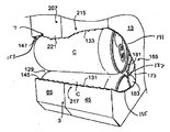
図1は、本発明の第1の実施形態に従い、概して3(図2〜7)で示されたカートンを形成するために使用される、概して1で示されたブランクの第1の外側2の平面図である。ブランク1は、縦軸L1と横軸L2を有する。図2に示されているように、カートン3は、概して、長方形の形状で、3×4の配置に12の円筒形容器C(図7)を保持するために構成される。図示された実施形態では、カートン3は、概して5で示された斜角コーナーを有するが、本発明の範囲から逸脱することなく、カートン3は、その他の形状にすることができ、その他の構成(例えば2×6、3×6、2×6×2、3×4×2など)で同じまたは異なる数の容器Cを保持することができることが理解される。以下に詳細を説明するように、カートン3は、カートン1の容器Cを取ることができるように、概して7で示されたディスペンサを有する。
FIG. 1 shows a first outer side 2 of a blank, generally designated 1, used to form a carton, generally designated 3 (FIGS. 2-7), according to a first embodiment of the invention. It is a top view. Blank 1 has a vertical axis L1 and a horizontal axis L2. As shown in FIG. 2, the
ブランク1は、第1の横方向の折り目15で第1のサイドパネル13に折り曲げ可能に接続される第1のトップフラップまたはパネル11と、第2の横方向の折り目21で第1のサイドパネル13に接続されるボトムパネル19と、第3の横方向の折り目27でボトムパネル19に折り曲げ可能に接続される第2のサイドパネル25と、第4の横方向の折り目33で第2のサイドパネル25に折り曲げ可能に接続される第2のトップフラップまたはパネル31と、を備える。
The blank 1 includes a first top flap or
第1のトップパネル11は、それぞれの縦方向の折り目39、41で第1のトップ端部パネル35および第2の端部フラップ37に折り曲げ可能に接続される。第1のサイドパネル13は、それぞれの縦方向の折り目49、51で第1のサイド端部フラップ45と第2のサイド端部フラップ47に折り曲げ可能に接続される。ボトムパネル19は、それぞれの縦方向の折り目59、61で第1のボトム端部フラップ55と第2のボトム端部フラップ57に折り曲げ可能に接続される。第2のサイドパネル25は、それぞれの縦方向の折り目69、71で第1のサイド端部フラップ65と第2のサイド端部フラップ67に折り曲げ可能に接続される。第2のトップパネル31は、それぞれの縦方向の折り目79、81で第1のトップ端部フラップ75と第2のトップ端部フラップ77に折り曲げ可能に接続される。図示された実施形態では、ブランク1の第1のトップパネル11は、概して85で示される第1のハンドル口を有し、第2のトップパネル31は、概して87で示される第2のハンドル口を有する。
The first
図示された実施形態では、第1のサイドパネル13の第1と第2のサイド端部フラップ45、47は、各々、それぞれの縦方向の折り目93、95でサイド端部フラップに接続されるそれぞれの接着フラップ89、91を有する。一実施形態では、第1と第2のトップ端部パネル35、37の各々は、各々のトップ端部フラップのトップコーナーパネル103、105を形成するように、縦方向の折り目39、41から横方向に離間して、概して平行な、それぞれの中間縦方向の折り目97、99を含む。同様に、第2のトップパネル31の第1と第2のトップ端部フラップ75、77は、各々、それぞれのトップコーナーパネル111、113を形成するように、縦方向の折り目79、81から横方向に離間して、概して平行なそれぞれの中間縦方向の折り目107、109を有する。第1と第2のボトム端部フラップ55、75は、各々、各ボトム端部フラップのボトムコーナーパネル121、123を形成するように、縦方向の折り目59、61から横方向に離間して、概して平行な中間縦方向の折り目117、119を有する。以下に詳細を説明するように、トップコーナーパネル103、105、111、113は、組み立てられたカートン3のトップ斜角コーナー5を形成し、ボトムコーナーパネル121、123は、組み立てられたカートンのボトム斜角コーナーを形成する。コーナーパネル103、105、111、113、121,123は、本発明の範囲から逸脱することなく、ブランク1から省略される可能性があることが理解されよう。さらに、ブランク1は、本発明の範囲から逸脱することなく、縦方向の折り目39、49、59、69および79は、単独の連続した縦方向の折り目で置換し、縦方向の折り目41、51、61、71、81は、単独の連続した縦方向の折り目で置換するように、構成される可能性がある。
In the illustrated embodiment, the first and second side end flaps 45, 47 of the
ディスペンサ7は、カートンブランク1に取り外し可能に取り付けられるディスペンサパネル127を含む。ディスペンサパネル127がカートン3から取り外されると、ディスペンサ7のディスペンサ開口129(図7)は、容器Cをカートンから選択的に取り出せるように、露出する。図1に示されているように、ディスペンサパネル127は、接着フラップ89の外側端から縦方向の折り目49まで、サイドフラップ45で横方向に延在する第1の切取線131と、第1の切取線から離間し、接着フラップの外側端から縦方向の折り目49まで、概して横方向に延在する第2の曲線の切取線133によってブランク1に画定される。図示された実施形態では、第2の切取線133は曲線なので、第1と第2の切取線は、接着フラップ89の外側端よりも、縦方向の折り目49で縦方向の距離が大きく離間する。第3の切取線135は、第1の切取線131と縦方向の折り目49との交差点から第1のサイドパネル13へ、概して横方向に延在し、第1のサイドパネルに配置された第4の切取線137と交差する。第5の切取線141は、第2の切取線133と縦方向の折り目49の交差点から第1のサイドパネル13へ斜めに延在し、第4の切取線137と交差する。第4の切取線137は、概して、アーチ状で、第1のサイドパネル13のディスペンサ127パネルの端部を画定するように、第1のサイドパネルの第3と第5の切取線135、141に接続する。
The
ディスペンサ7は、サイドフラップ65でフラップの外側端から縦方向の折り目69まで横方向に延在する第6の切取線145と、第6の切取線から離間して、フラップ65の外側端から縦方向の折り目69まで概して横方向に延在する第7の曲線の切取線147を含む。図示した実施形態では、第7の切取線147は曲線なので、第6と第7の曲線145、147は、フラップ65の外側端よりも、縦方向の折り目69で縦方向の距離が大きく離間する。第8の切取線149は、第6の切取線145と縦方向の折り目69との交差点から第2のサイドパネル25へ、概して横方向に延在して、第2のサイドパネルに配置された第9の切取線151と交差する。第10の切取線153は、第7の切取線147と縦方向の折り目69との交差点から第2のサイドパネル25へ、概して斜めに延在し、第9の切取線151と交差する。第9の切取線151は、概して、アーチ状で、第2のサイドパネル25のディスペンサ127パネルの端部を画定するように、第2のサイドパネル25の第8と第10の切取線149、153を接続する。図示した実施形態では、第1、第2、第3、第4、および第5の切取線131、133、135、137、141は、端部フラップ45、および、サイドフラップ65とサイドパネル25の第6、第7、第8、第9および第10の切取線145、147、149、151、153によって画定されるディスペンサパネルの第2の部分159の鏡像(組み立てられていないブランク1を示す図1に示されているように)であるサイドパネル13のディスペンサパネル127の第1の部分157を画定する。
The
ブランク1は、第1のサイドパネル13に、概して165で示された第1のアクセスパネルと、第2のサイドパネルに、概して167で示された第2のアクセスパネルと、を含む。第1と第2のアクセスパネル165、176によって、ディスペンサパネル127は、いずれか(または両方の)側面端から掴むことや、カートン1から取り出すことができるようになる。あるいは、本発明の範囲から逸脱することなく、ブランク1は、第1と第2のアクセスパネル165、167のうちの1つだけを有する場合がある。
The blank 1 includes a first access panel, generally designated 165, on the
第1のアクセスパネル165は、第3と第5の切取線135,137に対する交差点を超えて延在するアーチ状の第4の切取線137の端部の間を延在する縦方向の折り目175によって、サイドパネル13に折り曲げ可能に接続される作動パネル173を備える。アクセスパネル165は、第1と第2の曲線の折り目185、187によって作動パネル173に折り曲げ可能に接続される2つのアクセスフラップ181、183を含む。曲線の折り目185、187の各々の第1の端部は、縦方向の折り目175のそれぞれの端部から延在し、曲線の折り目のそれぞれの第2の端部は、アーチ状の第4の切取線137の中間点で概して収束する。図1に示されているように、2つのアクセスフラップ181、183は、概して花弁形状で、第4のアーチ状の切取線137の一部とそれぞれの曲線の折り目185、187によって画定される。
The
第2のサイドパネル25の第2のアクセスパネル167は、概して、第1のアクセスパネル165のように構築される。第2のアクセスパネル165は、アーチ状の第9の切取線151の端部の間を延在する縦方向の折り目193によって、サイドパネル25に折り曲げ可能に接続される作動パネル191と、第1と第2の曲線の折り目201、203によって作動パネル191に折り曲げ可能に接続される2つの花弁状のアクセスフラップ195、197と、を含む。
The
カートン3は、まず、第1のトップパネル11を第2のトップパネル31に重ね合わせて、2つのトップパネルをのり付けまたは他の方法で接着することによって、ボトムパネル19、第1のサイドパネル13、接着した第1と第2のトップパネル11、31、および第2のサイドパネル25が、概して筒状のスリーブを形成するように開くまたは設定できるように、ブランク1から組み立てることができる。概して筒状のスリーブは、例えば、概して207と示された(図2)第1の端部パネルを形成するように、カートン3の1つの端部で端部フラップ35、45、55、65、75を折り曲げて、接着することによって、および、概して209と示された第2の端部パネルを形成するように、カートンのもう一方の端部で端部フラップ37、47、57、67、77を折り曲げて、接着することによって、閉じることができる。図示された実施形態では、コーナーパネル103、105、111、113を接着した第1と第2のトップパネル11、31に対して斜角に配置するように、それぞれの横方向折り目39、41、79、81の周囲でそれぞれのトップ端部フラップ35、75、37、77を内側に折り曲げることと、それぞれの中間折り目103、105、107、109の周囲でトップ端部フラップを下側に折り曲げることによって、端部パネル207、209を閉じると、カートン3のトップ斜角コーナー5が形成される。ボトム斜角コーナー5は、各ボトムコーナーパネルをボトムパネル19に対して斜角に配置するように、それぞれの横方向折り目59、61の周囲でそれぞれのボトム端部フラップ55,57を上側に折り曲げることと、それぞれの中間折り目117、119の周囲でボトム端部フラップを上側に折り曲げることによって、形成される。サイドフラップ45、65は、その後、カートン3の第1の閉口端部207を形成するように重ね合わせることができ、サイドフラップ47、67は、カートンの第2の閉口端部209を形成するように重ね合わせることができる。容器Cまたはその他の品物は、例えば、カートン3の1つまたは両方の端部207、209が端部フラップ35、45、55、65、75およびまたは端部フラップ37、47、57、67、77によって閉じられる前に、いつでもスリーブに入れることができる。
The
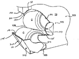
図2は、図1で図示されたブランク1から組み立てられたカートン3の斜視図であり、容器Cが装填されていて、第1と第2の端部207、209が閉じられている。図3〜7に示されているように、また、許容される方法に従い、以下に説明するように、ディスペンサ開口129を露出するようにディスペンサパネル127を取り外すことによって、容器Cをカートン3から選択的に取り出すことができるように、ディスペンサ7を開くことができる。図3〜6に示されているように、ディスペンサパネル127の第1の部分157の片側端は、カートン3の第1のアクセスパネル165を押すことによって、ユーザが掴むために露出することができる。図3および4に示されているように、圧力を作動パネル173に加えて、作動パネルを内側に押して、アクセスフラップ181、183を、それぞれの曲線の折り目185、187周りに外方に回動させる。アクセスフラップ181、183が回動すると、アクセスフラップはアーチ状の第4の切取線137に沿ってディスペンサパネル127から分離する(例えば、切り取られる)。図5に示されているように、ディスペンサパネル127からアクセスフラップ181、183を分離後、アクセスフラップの端部とディスペンサパネルの端部の間に少なくとも1本の指を挿入することによって、ディスペンサパネルの第1の部分157の端部がユーザによって掴まれる。カートンからディスペンサパネルの取り外しを開始すべく、パネルの第1の部分157を掴み、ディスペンサパネルの端部を、第3と第5の切取線135、141(図6)に沿ってパネルを切り取る方向に引っ張ることによって、ディスペンサパネル127は、取り外される。図7と図8に示されているように、ディスペンサパネル127は、第1、第2、第6、第7、第8、第9、および第10の切取線131、133、145、147、149、151、153に沿ってさらに切り取ることによって、カートン3から完全に取り除くことができる。図7に示されているように、アクセスパネル165は、典型的に、ディスペンサパネル127の取り外し後、折り目175に沿って、サイドパネル13に取り付けられたままになる。第2のアクセスパネル165は、カートン3の反対側(非表示)で第9の切取線151に沿って切り取ることによって、ディスペンサパネル127の第2の部分159の取り外し後、サイドパネル25に取り付けられたままになる。
FIG. 2 is a perspective view of the
カートン3は、第1または第2のアクセスパネル165、167のいずれかから、ディスペンサパネルを使用することができるようにすることによって、ディスペンサパネル127の右手または左手どちらかで取り外すように構成されていることが理解される。さらに、本発明の範囲から逸脱することなく、カートン3は、1つのアクセスパネルだけを有することができる。また、本発明の範囲から逸脱することなく、カートン3は、カートンの第2の端部209に第2のディスペンサ(非表示)を有することができる。
The
ディスペンサ7の第1、第3、第6および第8の切取線131、135、145、149は、カートン3の閉口端部207に、概して215で示される(図2)下側(第1)の切取線を形成し、第2、第5、第7および第10の線133、141、147、153は、カートンの閉口端部に概して217で示される上側(第2)の切取線を形成する。第1の実施形態に従い、ディスペンサパネル127が取り外される際に、容器Cがディスペンサ開口129の外側へ転がり出ることを防ぐようにして、ディスペンサ7のトップとボトムの切取線215、217は、ボトムパネル19の上方で離間している。例えば、そして、第1の実施形態に従い、ボトムの切取線215は、ボトムパネル13から測定すると、容器Cの直径の約40%から80%の間の高さH2に存在して、カートン3からボトム容器が転がり出ることを防ぐ。第1の実施形態に従い、閉口端部207のトップ切取線217は、ボトム列の容器Cの直径に中間列の容器の直径未満の距離を足したに等しい、高さH1に配置されて、カートン3から中間列の容器が転がり出ることを防ぐ。一実施形態では、トップ切取線217は、ボトム列の容器Cの直径に中間列の容器の直径の約60%から約90%の間の距離を足したものに等しい、高さに配置される。
The first, third, sixth and
第1の実施形態に従い、ディスペンサパネル127が取り外される際に、カートン3に全ての容器Cを保持するのに十分な高さに存在し、切取線は、両方の軸の端部で取り外される容器を掴むことによって、容器を簡単に取り外すことができる十分な距離でボトム切取線215とトップ切取線217とが離間している。トップ切取線217の湾曲によって、カートン3に容器Cの保持を促進し、取り外す容器を掴みやすくする。トップ切取線217は、カートン3の保持力を増加させるリップ221を形成する閉口端部207の中央線近くに下側部分を有する。図示された実施形態では、リップ221は、概して、リップがディスペンサ開口129の中間で下方向に延在するように、カートン3の閉口端部207の中央に配置される。トップ切取線217は、容器を掴むために、容器Cの端部の露出を増加できるように、リップ221からそれぞれのサイドパネル13、25に向かって上方に湾曲する。トップ切取線217の高さH1は、リップ221を形成する切取線の低点から測定される。ボトム切取線215も、本発明の範囲から逸脱することなく、湾曲させるようにしてもよいことが理解される。
According to the first embodiment, when the
図7に示されているように、カートン3のディスペンサ開口129の端部が、ディスペンサ7の切取線131、133、135、137、141、145、147、149、151、153の形状に対応する。ディスペンサ開口129は、図示された実施形態の3×4の配置においてリップ221が容器Cの中間列または第2の列を保持するような形状である。ディスペンサ開口129は、ディスペンサ開口から露出した第2の列の容器を掴んで取り外すことができるように、サイドパネル13、25の第2の列の露出した容器Cを取ることができるような形状でもある。ディスペンサ7および/またはカートン3は、本発明の範囲から逸脱することなく、容器の他の列または行を保つ形状など、その他の形状や配列とすることができる。
As shown in FIG. 7, the end of the
図2に示されているように、上部と下部の切取線は、最小距離D1の約2.3インチ(58mm)および最大距離D2の約2.6インチ(66mm)離間する。図示された実施形態では、最小距離D1は、カートン5の端部207のリップ221のほぼ低点に位置し、最大距離D2は、端部フラップ45、65をサイドパネル13、25にそれぞれ接続する折り目49,69近くのリップのいずれかの側に位置する。高さH1は、少なくとも約4.6インチ(117mm)にすることができる。一実施形態では、高さH2は少なくとも約2.3インチ(66mm)にすることができ、容器Cは少なくとも約2〜1/2インチ(63mm)の直径を有することができる。上部と下部の切取線は、本発明から逸脱することなく、代替の形状および配置にすることができる。最小距離D1および最大距離D2など、しかしこれらに限定されず、提供されている寸法情報は、典型的例のみであって、列挙されている寸法より大きく、または小さくすることができ、本発明の範囲を限定することを意図するものではないことが理解される。
As shown in FIG. 2, the upper and lower tear lines are separated by a minimum distance D1 of about 2.3 inches (58 mm) and a maximum distance D2 of about 2.6 inches (66 mm). In the illustrated embodiment, the minimum distance D1 is located approximately at the low point of the
図8は、本発明の第2の実施形態の、概して303と示されているカートンを形成するための、概して301と示されているブランクを示す。第2の実施形態のカートン303は、第1の実施形態のカートン3にほぼ類似するが、カートン303は、容器Cを、より容易に取り出すことができるように、ディスペンサ開口129を拡大できるようにする、概して305(図9)で示されているヒンジを含む点が異なる。従って、同様な参照番号は、第1と第2の実施形態の類似または同一な機能を示すために使用されている。ヒンジは、ディスペンサ7の第3の切取線135から横方向の折り目21まで延在する、ブランク301の第1の曲線の切取線311と、ディスペンサの第8の切取線149から横方向の折り目27まで延在する第2の曲線の切取線313と、を含む。ディスペンサ7の第1および第2の曲線の切取線311、313、および、第1、第3、第6および第8の切取線131、135、135、141、149は、カートン303の回動フラップ315を画定する。図示された実施形態では、回動フラップ315は、サイド端部フラップ45,65の少なくとも一部と、第1のサイドパネル13と、第2のサイドパネル25と、を備える。回動フラップ315は、本発明から逸脱することなく、その他の形状および配置とすることができる。
FIG. 8 shows a blank, generally designated 301, for forming a carton, generally designated 303, of a second embodiment of the present invention. The
ディスペンサパネル127は、第1の実施形態の上記と同様な方式でカートン303から取り外すことができる。ディスペンサ開口129を露出するようにディスペンサパネル127を取り外した後、回動フラップ315を掴み、カートン303の内側から外側へ引っぱることができるので、フラップはヒンジ305のそれぞれの第1および第2の曲線311、313周りに回転する。ヒンジ305は、回動フラップ315の運動が、カートンの容器Cをより容易に取り出すことができるように、ディスペンサ開口129を拡大することができる。特に、回動フラップ315は、ディスペンサ開口129が拡大するように下方に回転することが可能であるため、ボトム容器Cを容易に掴んで容器303から取り出すことができるようになる。
The
本発明は、品物を容易に取り出すことを可能にする追加の開口機能などの多様な機能、および、カートンの前後の端部に品物を配置する傾斜機能を含むカートンで使用することが可能である。 The present invention can be used in a carton that includes a variety of functions, such as an additional opening function that allows the item to be easily removed, and a tilt function that places the item at the front and rear ends of the carton. .
本発明の実施形態のいずれかに従うブランクは、例えば、コーティングされた板紙や同様な素材から形成することが可能である。例えば、ブランクの内側および/または外側は、クレーコーティングを塗布することが可能である。その後、クレーコーティングに、製品、広告、価格コード、およびその他の情報または画像を印刷することができる。その後、ブランクは、ブランク上に印刷された情報を保護するように、ニスを塗布することができる。また、ブランクは、例えば、湿気保護層などで、ブランクの片面または両面をコーティングすることができる。上述の実施形態に従い、ブランクは、普通紙よりも重く、剛性が強くなるような厚みの板紙で製造することができる。また、ブランクは、ダンボール紙、硬化紙、または、カートンが上記のように少なくとも一般的に機能できるために適した特性を有する、その他任意の素材など、他の素材から製造することが可能である。さらに、ブランクは、選択したパネルまたはパネルセクションに1枚以上のシート状の素材でラミネートまたはコーティングすることも可能である。 A blank according to any of the embodiments of the present invention can be formed, for example, from coated paperboard or similar material. For example, a clay coating can be applied to the inside and / or outside of the blank. The clay coating can then be printed with products, advertisements, price codes, and other information or images. The blank can then be varnished to protect the information printed on the blank. The blank can be coated on one side or both sides of the blank with, for example, a moisture protective layer. In accordance with the above-described embodiment, the blank can be made of paperboard that is heavier than plain paper and thick enough to be rigid. The blank can also be manufactured from other materials, such as cardboard, hardened paper, or any other material that has suitable properties for the carton to function at least generally as described above. . Furthermore, the blank can be laminated or coated with one or more sheet-like materials on selected panels or panel sections.
「線」という用語は、本明細書では、単なる直線だけではなく、湾曲、曲線または角度を付けて配置された線など、その他の種類の線も含む。 The term “line” as used herein includes not only straight lines but also other types of lines such as curved, curved or angled lines.
上記の実施形態は、のりによって接着された1つ以上のパネルを有するとして説明される。「のり」という用語は、カートンパネルを定位置に固定するために一般的に使用されるすべての方式の接着に及ぶことを意図する。 The above embodiments are described as having one or more panels bonded by glue. The term “paste” is intended to cover all types of bonding commonly used to secure a carton panel in place.
典型的な実施形態によると、折り目は、必ずしも直線ではないが、それに沿って折り畳むことを促進する実質的に直線のいかなる弱化の形式でもありうる。本発明の範囲を狭めることを目的としないが、より具体的には、折り目は、望ましい弱化線に沿って、素材に破砕あるいは押下部分を形成する、鈍いスコアリングナイフなどで形成された線などのスコアライン、望ましい弱化線に沿って、素材に部分的に延在する切り目、および/または望ましい弱化線に沿って、素材に部分的におよび/または完全に通過して延在する一連の切り目、およびこれらの機能の多様な組み合わせ、を含む。折り目を形成するために切り目が使用されている場合においては、典型的に、切り目は、分別のあるユーザが、誤まって折り目を切取線と見なす場合がある程度までには過度ではないようにする。 According to an exemplary embodiment, the fold is not necessarily a straight line, but can be any form of weakening of a substantially straight line that facilitates folding along it. Although not intended to narrow the scope of the present invention, more specifically, the crease is a line formed with a dull scoring knife or the like that forms a crushing or pressing portion in the material along the desired weakening line, etc. A series of cuts extending partially and / or completely through the material along the desired weakening line and / or along the desired weakening line And various combinations of these functions. In the case where cuts are used to form folds, the cuts are typically not excessive to the extent that a fractional user mistakenly considers the fold as a tear line.
例として、切取線は、望ましい弱化線に沿って素材に部分的に延在するスリット、および/または望ましい弱化線に沿って素材に部分的および/または完全に通過して延在する一連の離間したスリット、またはこれらの機能部の多様な組み合わせ、を含むことが可能である。より具体的な例として、ある種の切取線は、素材を完全に通過して延在する一連の離間したスリットの形で、典型的に切取線に沿って一時的に素材を接続するために、刻み目(例えば、素材の小さい橋状の部分)が、隣接のスリットの間に画定されるように、わずかに離間したスリットが隣接する。刻み目は、切取線に沿って裂くと破れる。刻み目は、典型的に、切取線の比較的小さい割合を占め、代替的には、切取線が連続した切り目線であるように、切取線から刻み目を省略または切り裂くことが可能である。つまり、各々の切取線が連続したスリットなどに置換されることは、本発明の範囲内である。例えば、切り目線は、本発明から逸脱することなく、連続したスリットにすることが可能、または、スリットよりも幅広い可能性がある。 By way of example, the tear lines are slits that partially extend into the material along the desired weakening line, and / or a series of spaced apart that extend partially and / or completely through the material along the desired weakening line It is possible to include slits or various combinations of these functional parts. As a more specific example, some types of tear lines are in the form of a series of spaced slits that extend completely through the material, typically indented to temporarily connect the material along the tear line. Slightly spaced slits are adjacent so that (eg, a small bridge-like portion of material) is defined between adjacent slits. A score is broken when it tears along the tear line. The indentation typically occupies a relatively small percentage of the cut line and, alternatively, the indent can be omitted or cut from the cut line so that the cut line is a continuous cut line. That is, it is within the scope of the present invention that each cut line is replaced with a continuous slit or the like. For example, the score line can be a continuous slit or can be wider than the slit without departing from the invention.
本発明の前述の説明は、本発明の多様な実施形態を図示して説明された。本発明の範囲から逸脱することなく、上記の構成に多様な変更を加えることが可能であるので、上記の説明に含まれたあるいは添付の図面に示されたすべての事柄は、説明のためであり、限定を意味するものではないと解釈すべきであると意図される。さらに、本発明の範囲は、請求項の範囲内である、上記に説明した実施形態の多様な変形、組み合わせ、代替などに及ぶ。これに加えて、本開示は、本発明の選択された実施形態のみを示して説明するが、本発明は、その他多様な組み合わせ、変更および環境において使用することが可能であり、本明細書に示されたように、発明概念の範囲内の変更または変形、上記の教示に相応して、および/または関連分野の技術または知識内で可能である。さらに、それぞれの実施形態の一定の機能および機能部は、本発明の範囲から逸脱することなく、選択的に交換およびその他の説明されたおよび説明されていない本発明の実施形態に適用することができる。 The foregoing description of the invention has been described with reference to various embodiments of the invention. Since various modifications can be made to the above configuration without departing from the scope of the invention, all matters contained in the above description or shown in the accompanying drawings are for purposes of illustration. It is intended and should not be construed as limiting. Further, the scope of the present invention covers various modifications, combinations, substitutions, etc. of the above-described embodiments within the scope of the claims. In addition, although this disclosure shows and describes only selected embodiments of the present invention, the present invention can be used in various other combinations, modifications, and environments, and is described herein. As indicated, modifications or variations within the scope of the inventive concept are possible, corresponding to the above teachings, and / or within the skill or knowledge of the relevant field. Furthermore, certain features and functional parts of each embodiment may be selectively exchanged and applied to other described and not described embodiments of the present invention without departing from the scope of the present invention. it can.
Claims (16)
前記カートンの内部周辺に少なくとも部分的に延在する複数のパネル(11、13、19、25、31)であって、トップパネル(11、31)、ボトムパネル(19)、第1のサイドパネル(13)、および第2のサイドパネル(25)を備える複数のパネルと、
前記複数のパネルのうちのそれぞれのパネルにそれぞれ折り曲げ可能に取り付けられる少なくとも2つの端部フラップ(35、45、55、65、75)であって、互いに重なり合うことによって、前記カートンの端部(207)を少なくとも部分的に閉じる、少なくとも2つの端部フラップ(35、45、55、65、75)と、
前記カートンから品物を取り出せるようにするためのディスペンサ(7)であって、前記カートンにおける切取線(215、217)によって少なくとも部分的に画定され、ディスペンサ開口(129)を少なくともさらに開くために、少なくとも部分的に取り外されるディスペンサパネル(127)を備え、前記ディスペンサパネル(127)は前記サイドパネル(13、25)のうちの少なくとも1つにおいて端部を有する、ディスペンサ(7)と、を備え、
前記切取線は、カートンの閉じられた端部において、上部切取線(217)と下部切取線(215)と、を備え、前記上部切取線と下部切取線は離間して、前記閉じられた端部にわたってそれぞれ延在し、
前記サイドパネル(13、25)の少なくとも一方にアクセスパネル(165、167)が設けられており、前記サイドパネルからの前記端部の分離を開始して前記端部を掴んでディスペンサパネル(127)を取り外すのために、前記アクセスパネルは内側に折り曲げられるようにされており、前記アクセスパネルは前記端部に隣接して、前記サイドパネルの少なくとも一方に折り曲げ可能に取り付けられ、前記アクセスパネル(165)は、前記第1および第2のサイドパネル(13、25)の一方に折り曲げ可能に接続される作動パネル(173)を備え、前記アクセスパネル(165)は、前記作動パネルに折り曲げ可能に接続される2つのアクセスフラップ(181、183)を備え、前記アクセスフラップは、前記ディスペンサパネルの端部を画定する切取線(137)に沿って前記ディスペンサパネル(127)から分離可能である、カートン。A carton (3) for accommodating a plurality of items (C), the carton comprising:
A plurality of panels (11, 13, 19, 25, 31) extending at least partially around the interior of the carton, the top panel (11, 31), the bottom panel (19), and the first side panel (13) and a plurality of panels comprising a second side panel (25);
At least two end flaps (35, 45, 55, 65, 75) that are foldably attached to the respective panels of the plurality of panels, and overlap each other to thereby end the carton (207 ) At least partially closing, at least two end flaps (35, 45, 55, 65, 75);
A dispenser (7) for allowing an item to be removed from the carton, at least partly defined by a tear line (215, 217) in the carton and at least further opening a dispenser opening (129) A dispenser panel (127) that is detachably removed, the dispenser panel (127) comprising a dispenser (7) having an end in at least one of the side panels (13, 25);
The tear line comprises an upper tear line (217) and a lower tear line (215) at the closed end of the carton, the upper tear line and the lower tear line being spaced apart and extending over the closed end, respectively. And
At least one of the side panels (13, 25) is provided with an access panel (165, 167), and separation of the end portion from the side panel is started and the end portion is grasped to hold a dispenser panel (127). The access panel is adapted to be folded inwardly, the access panel being foldably attached to at least one of the side panels adjacent to the end , and the access panel (165 ) Includes an operation panel (173) foldably connected to one of the first and second side panels (13, 25), and the access panel (165) is foldably connected to the operation panel. Two access flaps (181, 183), the access flaps comprising the dispenser It is separable from the dispenser panel (127) along the tear line (137) defining an end portion of the panel, the carton.
複数のパネル(11、13、19、25、31)であって、トップパネル(11、31)と、ボトムパネル(19)と、第1のサイドパネル(13)と、第2のサイドパネル(25)と、を備える複数のパネル(11、13、19、25、31)と、
前記複数のパネルのうちのそれぞれのパネルにそれぞれ折り曲げ可能に取り付けられた少なくとも2つの端部フラップ(35、45、55、65、75)と、
少なくとも1つのディスペンサパネル(127)を備えるディスペンサ機能部であって、該ディスペンサパネル(127)は、前記ブランクから前記ディスペンサパネルを少なくとも部分的に分離するために、切取線(215、217)によって少なくとも部分的に画定され、前記ディスペンサパネル(127)は前記サイドパネル(13、25)のうちの少なくとも一方に端部を有する、ディスペンサ機能部と、
前記サイドパネルのうちの少なくとも一方にあり、前記サイドパネルからの前記ディスペンサの端部の分離および前記ディスペンサパネル(127)の取り外しのために前記端部を掴むことを開始するように内側に折り曲げられるようにされている、アクセスパネル(165、167)であって、前記アクセスパネルは前記ディスペンサの端部に隣接して、前記サイドパネルのうちの少なくとも一つに折り曲げ可能に取り付けられている、アクセスパネル(165、167)とを備え、前記切取線は前記少なくとも2つの端部フラップに2つの離間する切取線(215、217)を備え、前記2つの切取線がそれぞれ前記少なくとも2つの端部フラップにわたって延在し、前記アクセスパネル(165)は、前記第1および第2のサイドパネル(13、25)のうちの一方に折り曲げ可能に接続される少なくとも1つの作動パネル(173)を備え、前記アクセスパネル(165)は、前記作動パネルに折り曲げ可能に接続される2つのアクセスフラップ(181、183)を備え、前記アクセスフラップは、前記ディスペンサパネル(127)の端部を画定する切取線(137)に沿って前記ディスペンサパネル(127)から分離可能である、ブランク。A blank (1) for forming a carton,
A plurality of panels (11, 13, 19, 25, 31), a top panel (11, 31), a bottom panel (19), a first side panel (13), and a second side panel ( 25), a plurality of panels (11, 13, 19, 25, 31),
At least two end flaps (35, 45, 55, 65, 75) each foldably attached to each of the plurality of panels;
A dispenser function comprising at least one dispenser panel (127), wherein the dispenser panel (127) is at least partially separated by a tear line (215, 217) to at least partially separate the dispenser panel from the blank. A dispenser function part, wherein the dispenser panel (127) has an end on at least one of the side panels (13, 25);
Located on at least one of the side panels and folded inward to initiate gripping of the end for separation of the end of the dispenser from the side panel and removal of the dispenser panel (127). An access panel (165, 167), wherein the access panel is foldably attached to at least one of the side panels adjacent an end of the dispenser. Panels (165, 167), wherein the tear lines comprise two spaced tear lines (215, 217) in the at least two end flaps, each of the two tear lines extending over the at least two end flaps The access panel (165) includes the first and second side panels. (13, 25) comprising at least one actuating panel (173) foldably connected to one of the access panels (165), wherein the access panel (165) is foldably connected to the actuating panel. 181, 183), wherein the access flap is separable from the dispenser panel (127) along a tear line (137) defining an end of the dispenser panel (127) .
カートン(3)を設けるステップを含み、該カートン(3)は、該カートンの内部周辺に少なくとも部分的に延在する複数のパネル(11、13、19、25、31)を有し、前記複数のパネルは、トップパネル(11、31)と、ボトムパネル(19)と、第1のサイドパネル(13)と、第2のサイドパネル(25)を備え、前記カートン(3)は、前記複数のパネルのそれぞれのパネルに折り曲げ可能にそれぞれ取り付けられた端部フラップ(35、45、55、65、75)を有し、前記端部フラップは互いに重なり合うことによって、前記カートンの閉じられた端部(207)を少なくとも部分的に形成し、前記カートン(3)は、前記カートンの切取線(215、217)によって少なくとも部分的に画定されるディスペンサパネル(127)を備えるディスペンサ(7)と、上部切取線(217)およびこれに離間する下部切取線(215)を備える前記切取線と、を有し、前記上部および下部切取線のそれぞれは前記閉じられた端部にわたって延在し、前記ディスペンサパネルは、前記サイドパネル(13、25)のうちの少なくとも一方に端部を、および前記サイドパネル(13、25)のうちの少なくとも一方にアクセスパネル(165、167)を有し、前記アクセスパネルは前記端部に隣接して、前記サイドパネルのうちの少なくとも一方に折り曲げ可能に取り付けられており、
当該方法は、
前記アクセスパネル(165、167)を内側に折り曲げることによって、前記ディスペンサパネルの前記端部から前記アクセスパネルを少なくとも部分的に分離し、前記ディスペンサパネル(127)にアクセスできるようにするステップと、
前記ディスペンサパネルの前記端部を掴み、前記上部および下部切取線に沿って、前記カートンを少なくとも部分的に切り取ることにより、前記カートンから前記ディスペンサパネルを少なくとも部分的に分離することによって、前記カートンにディスペンサ開口(129)を形成するステップと、を含み、
前記アクセスパネル(165)を内側に折り曲げるステップは、作動パネル(173)を内側に折り曲げることによって、前記カートンから2つのアクセスフラップ(181、183)を分離するステップを備え、前記カートンは、前記第1のサイドパネル(13)に少なくとも1つの切取線(135、141)と、前記第2のサイドパネル(25)に少なくとも1つの切取線(149、153)と、を備え、前記ディスペンサ開口は、前記第1のサイドパネルおよび前記第2のサイドパネルの切取線に沿って、前記カートンを切り取ること及び前記切取線(215、217)に沿って切り取ることによって形成される、方法。A method of opening the carton (3), the method comprising:
Providing a carton (3), the carton (3) having a plurality of panels (11, 13, 19, 25, 31) extending at least partially around the interior of the carton; The panel comprises a top panel (11, 31), a bottom panel (19), a first side panel (13), and a second side panel (25), and the carton (3) End panels (35, 45, 55, 65, 75) foldably attached to the respective panels of the panels, the end flaps overlapping each other, thereby closing the closed end of the carton (207) is at least partially formed and the carton (3) is at least partially defined by the carton tear lines (215, 217). A dispenser (7) with a lug (127) and an upper tear line (217) and a tear line with a lower tear line (215) spaced therefrom, each of the upper and lower tear lines being at the closed end The dispenser panel has an end on at least one of the side panels (13, 25) and an access panel (165, 167) on at least one of the side panels (13, 25). The access panel is adjacent to the end and is foldably attached to at least one of the side panels;
The method is
Separating the access panel from the end of the dispenser panel by folding the access panel (165, 167) inward to allow access to the dispenser panel (127);
A dispenser to the carton by grasping the end of the dispenser panel and at least partially separating the dispenser panel from the carton by at least partially cutting the carton along the upper and lower tear lines. Forming an opening (129) ,
Folding the access panel (165) inward comprises separating the two access flaps (181, 183) from the carton by folding the actuation panel (173) inward, the carton comprising the first At least one tear line (135, 141) on one side panel (13) and at least one tear line (149, 153) on the second side panel (25), wherein the dispenser opening is A method formed by cutting the carton along a cut line of one side panel and the second side panel and cutting along the cut lines (215, 217).
Applications Claiming Priority (3)
| Application Number | Priority Date | Filing Date | Title |
|---|---|---|---|
| US78187106P | 2006-03-13 | 2006-03-13 | |
| US60/781,871 | 2006-03-13 | ||
| PCT/US2007/006295 WO2007106478A2 (en) | 2006-03-13 | 2007-03-13 | Carton with dispenser |
Publications (3)
| Publication Number | Publication Date |
|---|---|
| JP2009530192A JP2009530192A (en) | 2009-08-27 |
| JP2009530192A5 JP2009530192A5 (en) | 2010-04-30 |
| JP5078984B2 true JP5078984B2 (en) | 2012-11-21 |
Family
ID=38430401
Family Applications (1)
| Application Number | Title | Priority Date | Filing Date |
|---|---|---|---|
| JP2009500430A Expired - Fee Related JP5078984B2 (en) | 2006-03-13 | 2007-03-13 | Carton with dispenser |
Country Status (11)
| Country | Link |
|---|---|
| US (1) | US7992765B2 (en) |
| EP (1) | EP1996481B1 (en) |
| JP (1) | JP5078984B2 (en) |
| CN (1) | CN101437731B (en) |
| AT (1) | ATE511479T1 (en) |
| AU (1) | AU2007225217B2 (en) |
| BR (1) | BRPI0708911B1 (en) |
| CA (1) | CA2644238C (en) |
| MX (1) | MX2008011670A (en) |
| NZ (1) | NZ571040A (en) |
| WO (1) | WO2007106478A2 (en) |
Families Citing this family (42)
| Publication number | Priority date | Publication date | Assignee | Title |
|---|---|---|---|---|
| US6974072B2 (en) * | 2003-02-22 | 2005-12-13 | Graphic Packaging International, Inc. | Paperboard carton with a new type of dispenser |
| DE602005022479D1 (en) | 2004-10-29 | 2010-09-02 | Graphic Packaging Int Inc | CARTON WITH OPENING DEVICE |
| AU2006242149B2 (en) * | 2005-05-03 | 2010-07-08 | Graphic Packaging International, Llc | Carton with dispenser |
| WO2007013976A2 (en) | 2005-07-22 | 2007-02-01 | Graphic Packaging International, Inc. | Carton with opening feature and blank |
| US20090121005A1 (en) * | 2006-06-23 | 2009-05-14 | Ho Fung Charles F | Cartons having dispensing configurations |
| US8033449B2 (en) * | 2006-06-23 | 2011-10-11 | Graphic Packaging International, Inc. | Cartons having dispensing configurations |
| US20090057384A1 (en) * | 2007-08-27 | 2009-03-05 | Angela Elizabeth Learn | Carton for dispensing products and method of using the same |
| CA2748924C (en) | 2009-01-16 | 2014-03-18 | Graphic Packaging International, Inc. | Carton with reinforcing insert |
| ES2477222T3 (en) | 2009-03-17 | 2014-07-16 | Graphic Packaging International, Inc. | Cardboard box with reinforced top panel |
| AU2010273467B2 (en) | 2009-07-14 | 2013-07-04 | Graphic Packaging International, Llc | Carton with insert |
| CA2771898C (en) | 2009-08-28 | 2014-10-14 | Graphic Packaging International, Inc. | Carton with insert |
| EP2509468A4 (en) * | 2009-12-11 | 2013-10-09 | Wrigley W M Jun Co | Display tray |
| US8281979B1 (en) * | 2009-12-11 | 2012-10-09 | John Pfanstiehl | Can dispenser for a carton |
| US8439194B2 (en) | 2010-05-25 | 2013-05-14 | Graphic Packaging International, Inc. | Carton with insert |
| MX2013002877A (en) | 2010-09-17 | 2013-04-08 | Graphic Packaging Int Inc | Carton with insert. |
| US8584860B2 (en) * | 2010-09-28 | 2013-11-19 | Menasha Corporation | Convertible carton |
| BR112014019126B1 (en) * | 2012-02-16 | 2021-01-12 | Graphic Packaging International, Llc | packaging to house a plurality of articles, blanket to form a package, blanket, and method of assembling a package |
| EP2841353B1 (en) | 2012-04-27 | 2021-04-07 | Graphic Packaging International, LLC | Carton with insert |
| WO2013173503A1 (en) * | 2012-05-15 | 2013-11-21 | Meadwestvaco Packaging Systems, Llc | Package and carton with dispenser and blank therefor |
| US8950654B2 (en) | 2012-06-08 | 2015-02-10 | Menasha Corporation | Folding carton with auto-erecting bottom |
| BR112015000512A2 (en) | 2012-07-17 | 2017-06-27 | Graphic Packaging Int Inc | pack for holding at least one article, blanket for forming a pack to contain at least one article, and method for forming a pack. |
| AU2013290754B2 (en) | 2012-07-17 | 2017-02-09 | Graphic Packaging International, Llc | Carton with insert |
| WO2014026087A1 (en) * | 2012-08-10 | 2014-02-13 | Graphic Packaging International, Inc. | Carton with dispenser |
| EP2996948B1 (en) | 2013-05-13 | 2018-04-18 | Graphic Packaging International, Inc. | Carton with article protection features |
| ES2660757T3 (en) | 2013-05-13 | 2018-03-26 | Graphic Packaging International, Inc. | Cardboard box with insertion element |
| WO2015089141A1 (en) | 2013-12-10 | 2015-06-18 | Graphic Packaging International, Inc. | Carton with article protection features |
| US9394094B2 (en) | 2014-02-28 | 2016-07-19 | Graphic Packaging International, Inc. | Carton with article protection features |
| US10322845B2 (en) | 2014-03-11 | 2019-06-18 | Graphic Packaging International, Llc | Carton with insert |
| JP6608840B2 (en) | 2014-03-11 | 2019-11-20 | グラフィック パッケージング インターナショナル エルエルシー | Carton with insert |
| EP3212532B1 (en) | 2014-10-30 | 2019-07-03 | Graphic Packaging International, LLC | Carton with handle |
| WO2016069697A1 (en) * | 2014-10-31 | 2016-05-06 | Graphic Packaging International, Inc. | Carton with handle |
| EP3297926B1 (en) | 2015-05-18 | 2020-11-18 | Graphic Packaging International, LLC | Carton with opening feature |
| WO2017023685A1 (en) | 2015-07-31 | 2017-02-09 | Graphic Packaging International, Inc. | Carton with dispenser |
| CA3017837A1 (en) * | 2016-05-06 | 2017-11-09 | Graphic Packaging International, Llc | Carton for articles |
| TWI800527B (en) * | 2017-09-18 | 2023-05-01 | 美商偉斯特洛克包裝系統有限責任公司 | Carton and carton blank |
| KR200492642Y1 (en) * | 2018-07-16 | 2020-11-16 | 씨제이제일제당 (주) | Package box and goods dispenser |
| USD898565S1 (en) | 2019-04-23 | 2020-10-13 | Graphic Packaging International, Llc | Carton |
| US10787288B1 (en) | 2019-05-17 | 2020-09-29 | Altria Client Services Llc | Blanks and packages for consumer items |
| USD947021S1 (en) | 2019-05-17 | 2022-03-29 | Altria Client Services Llc | Carton/dispenser package |
| US10787289B1 (en) | 2019-05-17 | 2020-09-29 | Altria Client Services Llc | Blank with platform panel and foot panel, and package with platform panel and foot panel |
| USD947022S1 (en) | 2019-05-17 | 2022-03-29 | Altria Client Services Llc | Carton/dispenser package |
| WO2023159243A1 (en) * | 2022-02-21 | 2023-08-24 | Westrock Packaging Systems, Llc | Carton and carton blank |
Family Cites Families (114)
| Publication number | Priority date | Publication date | Assignee | Title |
|---|---|---|---|---|
| US2005924A (en) | 1932-12-15 | 1935-06-25 | Sutherland Paper Co | Dispensing carton |
| US1925102A (en) | 1933-02-28 | 1933-09-05 | Evelyn G Levkoff | Display box |
| US2067749A (en) | 1934-08-18 | 1937-01-12 | Lester R Zimmerman | Container |
| US2115673A (en) | 1936-04-03 | 1938-04-26 | Marathon Paper Mills Co | Package for sheet material |
| US2299027A (en) | 1940-03-20 | 1942-10-13 | Edward J Novak | Display carton |
| US2669351A (en) | 1950-04-03 | 1954-02-16 | Goodyear Tire & Rubber | Package for liquids |
| US2754047A (en) | 1954-05-10 | 1956-07-10 | Olympia Brewing Company | Paperboard can carton |
| US3078032A (en) | 1960-08-17 | 1963-02-19 | Waldorf Paper Prod Co | Carrying container |
| US3133634A (en) | 1962-01-15 | 1964-05-19 | Wrigley W M Jun Co | Container assembly |
| US3128010A (en) | 1962-02-12 | 1964-04-07 | Mead Corp | Bottle carrier |
| US3228582A (en) | 1963-03-12 | 1966-01-11 | Nat Lock Co | Shipping and storage carton |
| US3178242A (en) | 1963-05-13 | 1965-04-13 | Anheuser Busch | One-piece dispensing carton for cylindrical objects |
| US3263861A (en) | 1964-06-09 | 1966-08-02 | Lawless Bros Container Corp | Dispensing carton |
| US3265283A (en) | 1964-12-11 | 1966-08-09 | Reynolds Metals Co | Shipping and dispensing carton |
| US3300115A (en) | 1965-04-05 | 1967-01-24 | Boise Cascade Corp | Compartmented dispensing carton formed from a single blank |
| US3346167A (en) | 1965-05-28 | 1967-10-10 | Olympia Brewing Company | Insulated reclosable beer carton |
| US3332594A (en) | 1965-10-22 | 1967-07-25 | Olin Mathieson | Container for shotgun shells |
| US3356279A (en) | 1966-02-23 | 1967-12-05 | Reynolds Metals Co | Shipping and dispensing container means and blanks therefor |
| US3540581A (en) | 1968-02-26 | 1970-11-17 | Lee Drechsler | Package construction for carrying horizontal superposed articles |
| US3533549A (en) | 1968-05-06 | 1970-10-13 | Domtar Ltd | Side carry carton |
| US3517858A (en) | 1968-08-08 | 1970-06-30 | Revnolds Metals Co | Reclosable dispensing carton |
| CA873185A (en) | 1969-09-08 | 1971-06-15 | E. Bishop Richard | Dispenser container |
| BE757851A (en) | 1969-10-23 | 1971-04-01 | Focke Heinz | PACKAGING IN CARTON OR CORRUGATED CARTON AND INTENDED FOR BOTTLES OR THE LIKE |
| JPS5421040U (en) * | 1977-07-13 | 1979-02-10 | ||
| US4155449A (en) | 1978-03-16 | 1979-05-22 | Olinkraft, Inc. | Returnable enclosed beverage carrier with improved top panel |
| US4214660A (en) | 1979-03-19 | 1980-07-29 | Hunt Letcher B Jr | Carton for beverage cans |
| US4417661A (en) | 1979-07-05 | 1983-11-29 | Champion International Corporation | Reclosable carton and blank therefor |
| US4256226A (en) | 1979-07-19 | 1981-03-17 | Pack Image, Inc. | Bottle container and method of erecting and loading the same |
| US4318474A (en) | 1979-11-19 | 1982-03-09 | The Continental Group, Inc. | 12-Pack carry back carton |
| US4376509A (en) | 1980-07-18 | 1983-03-15 | Schaffer George H | Liquid container with carrying handle |
| US4378877A (en) | 1981-04-13 | 1983-04-05 | Container Corporation Of America | Reusable enclosed carrier carton |
| US4375258A (en) | 1981-04-13 | 1983-03-01 | Container Corporation Of America | Reusable enclosed carrier carton |
| FR2506262A1 (en) | 1981-05-21 | 1982-11-26 | Socar | PACKAGING IN SEMI-RIGID MATERIAL SUCH AS CARTON FOR PACKAGING A LOT OF OBJECTS WITH A REVOLUTION AXIS |
| US4364509A (en) * | 1981-06-25 | 1982-12-21 | The Mead Corporation | Article carrier with dispensing feature |
| US4396143A (en) | 1981-08-31 | 1983-08-02 | Manville Service Corporation | Multiple article beverage package |
| US4417655A (en) | 1982-08-13 | 1983-11-29 | Westvaco Corporation | Shipping and display carton |
| FR2549010B3 (en) | 1983-07-12 | 1985-12-13 | Socar Parnalland | CARDBOARD OR SIMILAR PACKAGING FOR OBJECTS, SUCH AS BOTTLES, PROVIDED WITH A TEARABLE WALL |
| US4658984A (en) | 1984-07-09 | 1987-04-21 | Diamond Straw Incorporated | Shipping and dispensing container for drinking straws |
| JPH0113072Y2 (en) * | 1985-03-25 | 1989-04-17 | ||
| US4577762A (en) | 1985-06-27 | 1986-03-25 | James River Corporation Of Virginia | Reclosable package and carton blank and process for making the same |
| US4605128A (en) | 1985-07-22 | 1986-08-12 | Scott Paper Company | Dispensing carrier box and blank |
| EP0260813A3 (en) | 1986-09-17 | 1989-01-18 | St.Regis Packaging Limited | Improvements in packaging |
| US4974771A (en) | 1986-10-07 | 1990-12-04 | International Paper Company | Can carrier with integral handle |
| IT1213660B (en) | 1987-07-29 | 1989-12-29 | Cestind Centro Studi Indust Li | METHOD FOR THE PRODUCTION OF PACKAGING BOXES AND PACKAGING BOXES OBTAINED BY SUCH METHOD |
| US4919266A (en) * | 1989-06-09 | 1990-04-24 | The C. W. Zumbiel Co. | Carton with end wall display window |
| US4949845A (en) | 1989-11-14 | 1990-08-21 | Mebane Packaging Corporation | Folding carton with reclosable tuck and disposable hang panel |
| US5137211A (en) | 1990-08-06 | 1992-08-11 | Propper Manufacturing Co., Inc. | Dispensing carton |
| DE4028508C2 (en) | 1990-09-07 | 1994-01-20 | Sengewald Karl H Gmbh | Pack, in particular for compressible packaged goods |
| US5101642A (en) | 1990-09-14 | 1992-04-07 | The Mead Corporation | Means for cooling beverage containers in a carton |
| US5249681A (en) | 1992-01-13 | 1993-10-05 | The C. W. Zumbiel Co. | Carton dispenser system |
| GB2264101B (en) | 1992-02-17 | 1995-07-12 | St Regis Packaging Ltd | Improved transport/display carton |
| US5482185A (en) | 1994-01-14 | 1996-01-09 | Mcnaughton, Inc. | Apparatus for catching containers dispensed from a container storage unit |
| US5597114A (en) | 1994-02-16 | 1997-01-28 | Kramedjian; Armand J. | Interlocking modular product delivery system |
| US5425474A (en) | 1994-03-22 | 1995-06-20 | General Mills, Inc. | Cereal bowl shipping and dispensing package |
| US5577612A (en) | 1994-06-21 | 1996-11-26 | Lever Brothers Company, Division Of Conopco Inc. | Fabric softener sheet dispenser cartons |
| US5505372A (en) | 1994-10-28 | 1996-04-09 | Graphic Packaging Corporation | Carton blank and carton |
| KR100393939B1 (en) | 1994-12-13 | 2003-11-10 | 후지제록스오피스서플라이컴퍼니리미티드 | Carton for receiving cut sheet |
| GB9602540D0 (en) | 1996-02-08 | 1996-04-10 | British American Tobacco Co | Improved smoking article carton and blank therefor |
| US5664683A (en) | 1996-03-13 | 1997-09-09 | Norvey, Inc. | Packaging system |
| US5690230A (en) | 1996-04-02 | 1997-11-25 | Deroyal Industries, Inc. | Dispensing container for small flat items |
| US5690213A (en) | 1996-08-16 | 1997-11-25 | Shoyeido Corporation | Combination shipping and display carton |
| US5927498A (en) | 1996-11-15 | 1999-07-27 | Profile Packaging, Inc. | Packaging of stand-up, flexible pouches |
| US5794778A (en) | 1997-02-26 | 1998-08-18 | Riverwood International Corporation | Article carrier with strap-type handle and top panel access |
| US5881884A (en) | 1997-03-13 | 1999-03-16 | Avery Dennison Corporation | Shipping and display carton and blank therefor |
| US5875961A (en) | 1997-04-21 | 1999-03-02 | Tenneco Packaging | Non-directional paperboard pour spout |
| US5826783A (en) | 1997-06-09 | 1998-10-27 | The Mead Corporation | Two-tier can package having divider panel and method of forming the same |
| US5921398A (en) | 1998-01-12 | 1999-07-13 | Star-Kist Foods, Inc. | Storage and display carton |
| DE19831621A1 (en) | 1998-07-15 | 2000-01-20 | Focke & Co | Cigarette packet opening tab extends under perforated end flaps, simplifying opening procedure |
| US5924559A (en) | 1998-07-20 | 1999-07-20 | Jasper Foods, Inc. | Multiuse function display and dispensing carton |
| IT1311414B1 (en) | 1999-12-01 | 2002-03-12 | Gd Spa | FLAG BLOCKED FOR THE FORMATION OF A RIGID CUE FOR CIGARETTE PACKAGES. |
| US6176419B1 (en) | 2000-02-29 | 2001-01-23 | The Mead Corporation | Carton with article dispensing feature |
| US6283293B1 (en) | 2000-04-04 | 2001-09-04 | C. Brown Lingamfelter | Container for providing easy access to beverage cans |
| US6409077B1 (en) | 2000-05-09 | 2002-06-25 | Unilever Home & Personal Care Usa, Division Of Conopco, Inc. | Display carton |
| US6478219B1 (en) | 2000-11-15 | 2002-11-12 | The Mead Corporation | Carton with article dispenser |
| EE04936B1 (en) | 2000-12-12 | 2007-12-17 | The Mead Corporation | Multi-wall box, a package containing a box and a blank for forming a box |
| US6578736B2 (en) | 2001-01-09 | 2003-06-17 | Riverwood International Corporation | Carton with an improved dispensing feature |
| US6484903B2 (en) | 2001-01-09 | 2002-11-26 | Riverwood International Corporation | Carton with an improved dispensing feature in combination with a unique handle |
| US7059494B2 (en) | 2001-01-09 | 2006-06-13 | Harrelson Glenn R | Carton with an improved dispensing feature |
| USD459927S1 (en) | 2002-01-09 | 2002-07-09 | Recot, Inc. | Snack container dispenser |
| GB0202809D0 (en) | 2002-02-07 | 2002-03-27 | Riverwood Int Corp | A paperboard carton |
| US20030150759A1 (en) | 2002-02-14 | 2003-08-14 | White George H. | Carrying carton and can dispenser |
| US6929172B2 (en) | 2002-06-21 | 2005-08-16 | Meadwestvaco Packaging Systems, Llc | Severable carton wall |
| US20040099558A1 (en) | 2002-06-21 | 2004-05-27 | Oliff James R. | Dispensing feature with built-in combination retention and ad panel |
| DE20213450U1 (en) | 2002-08-27 | 2002-11-14 | Bacher und Demmler GmbH & Co. KG, 78571 Wurmlingen | System packaging with self-service opening |
| US6945450B2 (en) | 2002-08-27 | 2005-09-20 | Coors Global Properties, Inc. | Beverage cooler carton |
| US6866185B2 (en) | 2002-10-01 | 2005-03-15 | Graphic Packaging International, Inc. | Dispenser carton with tilt platform |
| US6866186B2 (en) | 2002-10-16 | 2005-03-15 | Graphic Packaging International, Inc. | Carton with a dispenser in the top panel for dispensing pouches |
| US20040089671A1 (en) | 2002-11-07 | 2004-05-13 | The C.W. Zumbiel Company | Carton with dispenser |
| US6604677B1 (en) | 2003-02-06 | 2003-08-12 | Riverwood International Corporation | Carton with top dispensing feature |
| US6918487B2 (en) | 2003-02-12 | 2005-07-19 | Graphic Packaging International, Inc. | Dispensing system for double stack carton |
| US6974072B2 (en) | 2003-02-22 | 2005-12-13 | Graphic Packaging International, Inc. | Paperboard carton with a new type of dispenser |
| US7237674B2 (en) | 2003-03-26 | 2007-07-03 | Meadwestvaco Packaging Systems, Llc | Carton with dispenser |
| US20060118606A1 (en) | 2003-03-26 | 2006-06-08 | Holley John M Jr | Carton with dispenser |
| US7104435B2 (en) | 2003-03-26 | 2006-09-12 | Meadwestvaco Packaging Systems Llc | Carton with dispenser |
| US6902104B2 (en) * | 2003-03-26 | 2005-06-07 | Meadwestvaco Packaging Systems, Llc | Carton with dispenser |
| US6997316B2 (en) | 2003-03-28 | 2006-02-14 | Graphic Packaging International, Inc. | Can dispensing package |
| JP2005053555A (en) * | 2003-08-06 | 2005-03-03 | Meadwestvaco Packaging Systems Llc | Package having dispenser |
| CA2535302A1 (en) | 2003-08-14 | 2005-03-10 | Bacou-Dalloz Eye & Face Protection, Inc. | Safety glasses with flexible frame and dual interchangeable lenses |
| US6968992B2 (en) | 2003-10-24 | 2005-11-29 | Graphic Packaging International, Inc. | Handle and top handle reinforcement for a paperboard carton |
| FR2861695B1 (en) | 2003-10-30 | 2005-12-09 | Aventis Pharma Sa | POLYGONAL BOX |
| US7225930B2 (en) | 2003-11-05 | 2007-06-05 | Graphic Packaging International, Inc. | Combination shipping carton and twin dispenser boxes |
| GB0326435D0 (en) | 2003-11-13 | 2003-12-17 | Graphic Packaging Int Inc | Dispensing package |
| BRPI0416677A (en) * | 2003-11-19 | 2007-02-13 | Meadwestvaco Packaging Systems | packaging box, packaging, method for dispensing at least one article, matrix for forming a packaging box, and method for preventing unwanted exit of articles from a container |
| US7073665B2 (en) | 2003-11-19 | 2006-07-11 | Meadwestvaco Packaging Systems Llc | Dispenser with detachable retention feature |
| US7000803B2 (en) * | 2003-12-02 | 2006-02-21 | The C.W. Zumbiel Company | Contoured carton with dispenser |
| US7168558B2 (en) | 2003-12-02 | 2007-01-30 | Graphic Packaging International, Inc. | Carton with an interlocking divider pad |
| US7195118B2 (en) * | 2004-01-30 | 2007-03-27 | Graphic Packaging International, Inc. | Beveled corner carton with an interlocking separator pad |
| US7240789B2 (en) | 2004-02-03 | 2007-07-10 | Graphic Packaging International, Inc. | Carton with an interlocking separator pad and dispenser |
| US20050189405A1 (en) | 2004-02-27 | 2005-09-01 | Jean-Manuel Gomes | Three by four can package dispensing carton |
| US20060054522A1 (en) | 2004-09-14 | 2006-03-16 | The Coca-Cola Company | Carton with article opening |
| AU2005302244B2 (en) | 2004-10-29 | 2010-06-10 | Graphic Packaging International, Inc. | Carton having improved opening features |
| DE602005022479D1 (en) * | 2004-10-29 | 2010-09-02 | Graphic Packaging Int Inc | CARTON WITH OPENING DEVICE |
| WO2006069166A1 (en) * | 2004-12-20 | 2006-06-29 | Meadwestvaco Packaging Systems, Llc | Carton with pressure sensitive opening device |
| US7909235B2 (en) | 2005-02-09 | 2011-03-22 | Mead Westvaco Packaging Systems, Llc | Carton with dispenser |
-
2007
- 2007-03-13 CA CA2644238A patent/CA2644238C/en active Active
- 2007-03-13 WO PCT/US2007/006295 patent/WO2007106478A2/en active Application Filing
- 2007-03-13 AT AT07752956T patent/ATE511479T1/en not_active IP Right Cessation
- 2007-03-13 US US11/685,393 patent/US7992765B2/en active Active
- 2007-03-13 BR BRPI0708911A patent/BRPI0708911B1/en active IP Right Grant
- 2007-03-13 EP EP07752956A patent/EP1996481B1/en active Active
- 2007-03-13 JP JP2009500430A patent/JP5078984B2/en not_active Expired - Fee Related
- 2007-03-13 CN CN2007800164014A patent/CN101437731B/en active Active
- 2007-03-13 MX MX2008011670A patent/MX2008011670A/en active IP Right Grant
- 2007-03-13 AU AU2007225217A patent/AU2007225217B2/en active Active
- 2007-03-13 NZ NZ571040A patent/NZ571040A/en not_active IP Right Cessation
Also Published As
| Publication number | Publication date |
|---|---|
| BRPI0708911B1 (en) | 2018-11-06 |
| EP1996481A2 (en) | 2008-12-03 |
| MX2008011670A (en) | 2008-09-22 |
| NZ571040A (en) | 2011-05-27 |
| WO2007106478A2 (en) | 2007-09-20 |
| CN101437731A (en) | 2009-05-20 |
| EP1996481B1 (en) | 2011-06-01 |
| US20070210144A1 (en) | 2007-09-13 |
| AU2007225217B2 (en) | 2011-05-19 |
| CA2644238A1 (en) | 2007-09-20 |
| WO2007106478A3 (en) | 2008-03-13 |
| WO2007106478A8 (en) | 2008-10-30 |
| JP2009530192A (en) | 2009-08-27 |
| US7992765B2 (en) | 2011-08-09 |
| BRPI0708911A2 (en) | 2011-06-14 |
| AU2007225217A1 (en) | 2007-09-20 |
| CN101437731B (en) | 2012-05-30 |
| CA2644238C (en) | 2011-01-25 |
| ATE511479T1 (en) | 2011-06-15 |
Similar Documents
| Publication | Publication Date | Title |
|---|---|---|
| JP5078984B2 (en) | Carton with dispenser | |
| JP4510090B2 (en) | Carton with opening feature | |
| US7604157B2 (en) | Carton with dispenser | |
| JP4875065B2 (en) | Carton with support | |
| US7703666B2 (en) | Carton with dispenser | |
| US7918384B2 (en) | Carton with dispenser | |
| JP4850283B2 (en) | Carton with dispenser | |
| JP2008531415A (en) | Carton with display features | |
| JP6250050B2 (en) | Carton with dispenser | |
| AU2007248577B2 (en) | Carton with vent openings, blank and folding method | |
| US8479973B2 (en) | Carton with handle |
Legal Events
| Date | Code | Title | Description |
|---|---|---|---|
| A521 | Request for written amendment filed |
Free format text: JAPANESE INTERMEDIATE CODE: A523 Effective date: 20100312 |
|
| A621 | Written request for application examination |
Free format text: JAPANESE INTERMEDIATE CODE: A621 Effective date: 20100312 |
|
| A977 | Report on retrieval |
Free format text: JAPANESE INTERMEDIATE CODE: A971007 Effective date: 20120215 |
|
| A131 | Notification of reasons for refusal |
Free format text: JAPANESE INTERMEDIATE CODE: A131 Effective date: 20120220 |
|
| A521 | Request for written amendment filed |
Free format text: JAPANESE INTERMEDIATE CODE: A523 Effective date: 20120521 |
|
| TRDD | Decision of grant or rejection written | ||
| A01 | Written decision to grant a patent or to grant a registration (utility model) |
Free format text: JAPANESE INTERMEDIATE CODE: A01 Effective date: 20120731 |
|
| A01 | Written decision to grant a patent or to grant a registration (utility model) |
Free format text: JAPANESE INTERMEDIATE CODE: A01 |
|
| A61 | First payment of annual fees (during grant procedure) |
Free format text: JAPANESE INTERMEDIATE CODE: A61 Effective date: 20120828 |
|
| FPAY | Renewal fee payment (event date is renewal date of database) |
Free format text: PAYMENT UNTIL: 20150907 Year of fee payment: 3 |
|
| R150 | Certificate of patent or registration of utility model |
Free format text: JAPANESE INTERMEDIATE CODE: R150 |
|
| R250 | Receipt of annual fees |
Free format text: JAPANESE INTERMEDIATE CODE: R250 |
|
| LAPS | Cancellation because of no payment of annual fees |