JP5078706B2 - Lighting device - Google Patents
Lighting device Download PDFInfo
- Publication number
- JP5078706B2 JP5078706B2 JP2008092572A JP2008092572A JP5078706B2 JP 5078706 B2 JP5078706 B2 JP 5078706B2 JP 2008092572 A JP2008092572 A JP 2008092572A JP 2008092572 A JP2008092572 A JP 2008092572A JP 5078706 B2 JP5078706 B2 JP 5078706B2
- Authority
- JP
- Japan
- Prior art keywords
- lighting
- power
- turned
- state
- timer
- Prior art date
- Legal status (The legal status is an assumption and is not a legal conclusion. Google has not performed a legal analysis and makes no representation as to the accuracy of the status listed.)
- Active
Links
Images


Classifications
-
- Y—GENERAL TAGGING OF NEW TECHNOLOGICAL DEVELOPMENTS; GENERAL TAGGING OF CROSS-SECTIONAL TECHNOLOGIES SPANNING OVER SEVERAL SECTIONS OF THE IPC; TECHNICAL SUBJECTS COVERED BY FORMER USPC CROSS-REFERENCE ART COLLECTIONS [XRACs] AND DIGESTS
- Y02—TECHNOLOGIES OR APPLICATIONS FOR MITIGATION OR ADAPTATION AGAINST CLIMATE CHANGE
- Y02B—CLIMATE CHANGE MITIGATION TECHNOLOGIES RELATED TO BUILDINGS, e.g. HOUSING, HOUSE APPLIANCES OR RELATED END-USER APPLICATIONS
- Y02B20/00—Energy efficient lighting technologies, e.g. halogen lamps or gas discharge lamps
- Y02B20/40—Control techniques providing energy savings, e.g. smart controller or presence detection
Landscapes
- Circuit Arrangement For Electric Light Sources In General (AREA)
Abstract
Description
本発明は、照明装置に関し、特に電源スイッチの入/切操作を行うことにより所望の点灯状態で光源を点灯させることができる照明装置に関する。 The present invention relates to lighting equipment, about the lighting equipment of the light source can be lit, especially in a desired lighting state by performing ON / OFF operation of the power switch.
屋内の天井又は壁などに設置された照明装置(照明器具)は、壁に設けられた電源スイッチ、照明器具から引き出された操作紐、あるいは赤外線リモコンなどを操作することにより、点灯又は消灯を行うことができる。また、利用者の好み、照明器具の設置場所又は時間帯などに応じて、光源の明るさを調整することができる調光機能を備えた照明器具も広く使用されている。 A lighting device (lighting fixture) installed on an indoor ceiling or wall is turned on or off by operating a power switch provided on the wall, an operation cord drawn from the lighting fixture, an infrared remote controller, or the like. be able to. In addition, lighting fixtures having a dimming function capable of adjusting the brightness of the light source according to the user's preference, the installation location of the lighting fixture or the time zone are also widely used.
照明器具の調光を行う方法として、例えば、屋内の壁に設けられた電源スイッチを操作し、電源スイッチがオン状態にある場合に、短時間の電源スイッチのオフ操作があったときに、照明器具の明るさを切り替える方法がある(特許文献1参照)。
特許文献1の照明器具では、短時間の電源スイッチのオフ操作があったか否かは、マイクロコンピュータに備えられたタイマ(カウンタ)等を用いて行っている。しかし、マイクロコンピュータに備えられたタイマには、例えば、±5%程度の誤差があるため、個々の照明器具に内蔵されたタイマには、ばらつきが生じる場合がある。このため、例えば、1つの電源スイッチで複数の照明器具を制御する場合に、短時間の電源スイッチのオフ操作をしたものの、タイマのばらつきによって短時間の電源オフ状態を検出できず、所定の明るさに切り替わらない照明器具が現われるという問題があった。
In the luminaire of
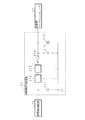
図9は従来の電源スイッチの操作による調光方法の概要を示す説明図である。図9の例では、複数の照明器具A〜Eを1つの電源スイッチ(例えば、屋内の壁に設けられた電源スイッチ)で点灯、調光(明るさの切り替え)、消灯することができるものである。また、図9において、斜線の部分は観式的に消灯割合を示す。図9に示すように、当初、すべての照明器具を全灯(100%の明るさ)で点灯し、短時間の電源オフ操作を行うことにより、75%調光に切り替えたとする。 FIG. 9 is an explanatory diagram showing an outline of a dimming method by operating a conventional power switch. In the example of FIG. 9, a plurality of lighting fixtures A to E can be turned on, dimmed (brightness switching), and turned off with one power switch (for example, a power switch provided on an indoor wall). is there. In FIG. 9, the shaded portion indicates the extinction ratio in a schematic manner. As shown in FIG. 9, it is assumed that all lighting fixtures are initially turned on with all lamps (100% brightness) and switched to 75% dimming by performing a power-off operation for a short time.
次に、75%調光から50%調光にすべく、再度、短時間の電源オフ操作を行ったところ、仮に照明器具Dに内蔵のマイクロコンピュータ(タイマ)が短時間の電源オフ状態を検出できなかったとする。この状態では、照明器具Dを除く他の照明器具は、50%調光で点灯するものの、照明器具Dは前回の調光モードである75%で点灯することになり、照明器具全体の調光レベルが同期しないという事態に陥る。 Next, in order to change from 75% dimming to 50% dimming, when the power was turned off again for a short time, the built-in microcomputer (timer) in the lighting fixture D detected a short time power off state. Suppose you couldn't. In this state, although the other lighting fixtures except the lighting fixture D are turned on at 50% dimming, the lighting fixture D is turned on at 75%, which is the previous dimming mode. It falls into the situation that the level does not synchronize.
この状態で、再度、短時間の電源オフ操作を行うことにより、各照明器具の明るさが切り替わる。すなわち、照明器具Dを除く他の照明器具は、50%調光から25%調光で点灯するものの、照明器具Dは前回の調光モードである75%から50%調光に切り替わることになり、照明器具全体の調光レベルが同期しないという事態が続く。このように、複数の照明器具の調光制御を行う場合、一旦1つの照明器具で短時間の電源オフ状態を検出することができない事態が発生すると、すべての照明器具の調光レベルが同一レベルにならず、また、調光レベルを揃えることが困難であった。このような照明環境は、利用者にとって不快感又は違和感を与えることになり、このような事態を改善することが望まれていた。 In this state, the brightness of each lighting fixture is switched by performing a power-off operation for a short time again. That is, the other lighting fixtures except for the lighting fixture D are turned on from 50% dimming to 25% dimming, but the lighting fixture D is switched from the previous dimming mode of 75% to 50% dimming. The situation continues that the dimming level of the entire lighting fixture is not synchronized. As described above, when dimming control of a plurality of lighting fixtures is performed, once a situation occurs in which it is impossible to detect a short-time power-off state with one lighting fixture, the dimming levels of all the lighting fixtures are the same level. In addition, it was difficult to adjust the light control level. Such a lighting environment gives an uncomfortable feeling or an uncomfortable feeling to the user, and it has been desired to improve such a situation.
本発明は斯かる事情に鑑みてなされたものであり、所望の点灯状態で光源を点灯させることができる照明装置を提供することを目的とする。 The present invention has been made in view of such circumstances, and an object thereof is to provide a lighting equipment which can be on the light source in a desired lighting state.
本発明に係る照明装置は、複数の光源の各々に、該複数の光源の各々の点灯状態を電源の切状態から入状態になるまでの第1経過時間に対応して制御する制御部を備える照明装置において、該各々の制御部は、前記電源の入状態から切状態になるまでの第2経過時間が所定の時間を経過した場合、前記複数の光源の各々の点灯状態を所定の点灯状態に制御し、前記複数の光源の点灯状態を同期させることを特徴とする。 An illumination device according to the present invention includes a control unit that controls each of a plurality of light sources in accordance with a first elapsed time until the lighting state of each of the plurality of light sources is changed from a power-off state to an on state. In the lighting device, each of the control units sets the lighting state of each of the plurality of light sources to a predetermined lighting state when a second elapsed time from when the power is turned on to when the power is turned off passes a predetermined time. controls to be characterized and Turkey synchronizes the lighting state of the plurality of light sources.
本発明に係る照明装置は、前記電源の入状態/切状態を検出する検出部と、前記電源の切状態から入状態になるまでの第1経過時間を計時する第1計時部と、前記電源の入状態から切状態になるまでの第2経過時間を計時する第2計時部とを備え、前記制御部は、前記第2経過時間が第2閾値より長い場合において、前記第1経過時間が第1閾値より短いとき、前記複数の光源を所定の点灯状態に制御するように構成してあることを特徴とする。 Lighting device according to the present invention, a detector for detecting the ON state / OFF state of the power source, a first time counting unit for counting a first elapsed time from the switching state of the power supply until the ON state, the power supply A second timing unit that counts a second elapsed time from the on-state to the off-state, and the control unit is configured to measure the first elapsed time when the second elapsed time is longer than a second threshold. when shorter than the first threshold value, and configured characterized tare Rukoto to control the plurality of light sources in a predetermined lighting state.
本発明に係る照明装置は、前記複数の光源の異なる点灯状態間の遷移情報を記憶する記憶部を備え、前記制御部は、前記第2経過時間が前記第2閾値より短い場合において、前記第1経過時間が前記第1閾値より短いとき、直近の点灯状態から記憶した遷移情報に応じて遷移した点灯状態で前記複数の光源を点灯すべく制御するように構成してあることを特徴とする。 The illumination device according to the present invention includes a storage unit that stores transition information between different lighting states of the plurality of light sources, and the control unit includes the first unit when the second elapsed time is shorter than the second threshold value. When one elapsed time is shorter than the first threshold value, the plurality of light sources are controlled to be turned on in a lighting state transitioned according to the transition information stored from the latest lighting state. .
本発明に係る照明装置は、前記制御部は、前記第1経過時間が前記第1閾値より長い場合、直近の点灯状態で前記複数の光源を点灯すべく制御するように構成してあることを特徴とする。 In the illumination device according to the present invention, the control unit is configured to control to turn on the plurality of light sources in the latest lighting state when the first elapsed time is longer than the first threshold. Features.
本発明にあっては、複数の光源の各々に対応して制御部を備えてあり、各制御部は、複数の光源それぞれの点灯状態を同期させる。点灯状態は、例えば、全灯状態、所定の調光モードなどであり、同期によりすべての光源の点灯状態を同一にすることができる。これにより、所望の点灯状態で光源を点灯させることができる。 In this invention, the control part is provided corresponding to each of several light sources, and each control part synchronizes each lighting state of several light sources . Lighting state, for example, all lighting conditions, and the like predetermined dimming mode, it is possible to equalize the lighting state of a more all light sources in synchronization. Thereby, the light source can be turned on in a desired lighting state.
また、照明装置は、電源の入状態(オン状態)から切状態(オフ状態)になるまでの第2経過時間が所定の時間を経過した場合に、複数の光源の点灯状態を同期させる。点灯状態は、例えば、全灯状態、所定の調光モードなどである。電源の入状態から切状態になるまでの第2経過時間を加味することにより、電源スイッチの入切操作だけで光源を所望の点灯状態に同期させることができる。なお、同期させるとは、複数の光源の点灯状態を同じ状態にすることである。例えば、電源スイッチの操作により所定の第1経過時間を検出したときに、光源の点灯状態を切り替え(例えば、調光モードを切り替える)、その後、電源スイッチの入切操作により第2経過時間が所定の時間を経過した場合には、複数の光源を予め定められた点灯状態(例えば、全灯状態、所定の調光モードなど)に同期させることができる。これにより、複数の照明装置を1つの電源スイッチの入切で点灯制御する場合に、照明装置全体の点灯状態を所定の点灯状態に設定することができるので、仮に照明装置全体の調光レベルが同一にならない事態が発生した場合でもすべての照明装置の調光レベルを容易に揃えることができる。 Further , the lighting device synchronizes the lighting states of the plurality of light sources when a second elapsed time from when the power is turned on (on state) to when it is turned off (off state) has passed a predetermined time. The lighting state is, for example, a full lighting state, a predetermined dimming mode, or the like. By taking into account the second elapsed time from when the power is turned on to when it is turned off, the light source can be synchronized with the desired lighting state only by turning on / off the power switch. Note that synchronizing means making the lighting states of a plurality of light sources the same. For example, when a predetermined first elapsed time is detected by operating the power switch, the lighting state of the light source is switched (for example, the dimming mode is switched), and then the second elapsed time is determined by turning on / off the power switch. When the time elapses, the plurality of light sources can be synchronized with a predetermined lighting state (for example, all lighting states, a predetermined dimming mode, etc.). Thereby, when lighting control of a plurality of lighting devices is performed by turning on / off one power switch, the lighting state of the entire lighting device can be set to a predetermined lighting state, so that the dimming level of the entire lighting device is temporarily Even when a situation where they are not the same occurs, the dimming levels of all the lighting devices can be easily aligned.
本発明にあっては、照明装置は、電源の入状態(オン状態)から切状態(オフ状態)になるまでの第2経過時間及び電源の切状態から入状態になるまでの第1経過時間に応じて、光源の点灯状態を制御する。すなわち、電源が切状態にある時間(第1経過時間)だけでなく、電源の入状態から切状態になるまでの第2経過時間を加味することにより、電源スイッチの入切操作だけで光源を所望の点灯状態に制御することができる。例えば、電源スイッチの操作により所定の第1経過時間を検出した場合に、第2経過時間が所定の閾値時間よりも短い場合には、従来のように点灯状態を切り替え(例えば、調光モードを切り替える)、第2経過時間が所定の閾値時間よりも長い場合には、予め定められた点灯状態(例えば、全灯状態、所定の調光モードなど)に制御することができる。これにより、複数の照明装置を1つの電源スイッチの入切で点灯制御する場合に、照明装置全体の点灯状態を所定の点灯状態に設定することができるので、仮に照明装置全体の調光レベルが同一にならない事態が発生した場合でもすべての照明装置の調光レベルを容易に揃えることができる。 In the present invention, the lighting device has a second elapsed time from the power-on state (on state) to the off state (off state) and a first elapsed time from the power-off state to the on state. The lighting state of the light source is controlled accordingly. That is, not only the time when the power is turned off (first elapsed time) but also the second elapsed time from when the power is turned on to when the power is turned off, the light source can be turned on only by turning on / off the power switch. It can be controlled to a desired lighting state. For example, when a predetermined first elapsed time is detected by operating a power switch, if the second elapsed time is shorter than a predetermined threshold time, the lighting state is switched as in the past (for example, the dimming mode is changed). When the second elapsed time is longer than a predetermined threshold time, it is possible to control to a predetermined lighting state (for example, a full lighting state, a predetermined dimming mode, etc.). Thereby, when lighting control of a plurality of lighting devices is performed by turning on / off one power switch, the lighting state of the entire lighting device can be set to a predetermined lighting state, so that the dimming level of the entire lighting device is temporarily Even when a situation where they are not the same occurs, the dimming levels of all the lighting devices can be easily aligned.
また、照明装置は、第2経過時間が第2閾値(例えば、10秒)より長い場合において、第1経過時間が第1閾値(例えば、2秒)より短いとき、光源を所定の点灯状態に制御する。所定の点灯状態は、それぞれの照明装置の点灯状態を同一にする状態であれば、全灯(100%調光)でもよく、あるいは、80%、50%などの調光状態でもよい。これにより、電源スイッチを操作して、電源を入状態にした時点から、例えば、10秒以上経過した時点で短時間(例えば、2秒以内)の電源切の操作の後電源入にした場合には、それぞれの照明装置の点灯状態は、所定の点灯状態に統一され、仮に調光レベルが揃わない事態になったとしても、かかる事態を解消してすべての照明装置の点灯状態を揃える(同期させる)ことができる。 In addition , in the case where the second elapsed time is longer than a second threshold (for example, 10 seconds), the lighting device sets the light source to a predetermined lighting state when the first elapsed time is shorter than the first threshold (for example, 2 seconds). Control. The predetermined lighting state may be all the lights (100% dimming) or the dimming state such as 80% or 50% as long as the lighting states of the respective lighting devices are the same. Thus, when the power switch is operated and the power is turned on, for example, when the power is turned on after a short-time operation (for example, within 2 seconds) after a lapse of 10 seconds or more. The lighting state of each lighting device is unified to a predetermined lighting state, and even if the dimming level does not match, the lighting state of all lighting devices is aligned (synchronized). Can).
本発明にあっては、照明装置は、光源の異なる点灯状態間の遷移情報を記憶してある。遷移情報は、例えば、全灯を含む各調光モードの切り替え順位などである。照明装置は、第2経過時間が第2閾値(例えば、10秒)より短い場合において、第1経過時間が第1閾値(例えば、2秒)より短いとき、直近の点灯状態から記憶した遷移情報に応じて遷移した点灯状態で光源を点灯する。これにより、電源スイッチを操作して、電源を入状態にした時点から、例えば、10秒以内に短時間(例えば、2秒以内)の電源切の操作の後電源入にした場合には、それぞれの照明装置の点灯状態を、所定の順序に従って切り替えることができる。また、短時間(例えば、2秒以内)の電源切の操作の後電源入の操作を繰り返すことにより、照明装置の点灯状態を順次切り替えることができ、所望の点灯状態に容易に設定することができる。 In this invention, the illuminating device has memorize | stored the transition information between the lighting states from which a light source differs. The transition information is, for example, the switching order of each dimming mode including all lamps. When the second elapsed time is shorter than the second threshold (for example, 10 seconds) and the first elapsed time is shorter than the first threshold (for example, 2 seconds), the lighting device stores the transition information stored from the latest lighting state. The light source is turned on in the lighting state transitioned according to. Thus, when the power switch is operated and the power is turned on, for example, when the power is turned on after a short-time operation (for example, within 2 seconds) within 10 seconds, The lighting state of the lighting device can be switched according to a predetermined order. Further, by repeating the power-on operation after the power-off operation for a short time (for example, within 2 seconds), the lighting state of the lighting device can be sequentially switched, and can be easily set to a desired lighting state. it can.
本発明にあっては、照明装置は、第1経過時間が第1閾値(例えば、2秒)より長い場合、直近の点灯状態(前回の点灯状態)で光源を点灯する。これにより、電源スイッチを操作して、例えば、電源切の操作をして2秒以上経過した時点で電源入にした場合には、点灯する前の点灯状態をそのまま維持して光源を点灯することができる。 In the present invention, when the first elapsed time is longer than the first threshold (for example, 2 seconds), the lighting device turns on the light source in the latest lighting state (previous lighting state). As a result, when the power switch is operated, for example, when the power is turned off when the power is turned off after 2 seconds, the light source is turned on while maintaining the lighting state before lighting. Can do.
本発明によれば、電源スイッチの入/切操作を行うことにより所望の点灯状態で光源を点灯させることができ、複数の照明装置を1つの電源スイッチの入切で点灯制御する場合に、照明装置全体の点灯状態を所定の点灯状態に設定することができるので、仮に照明装置全体の調光レベルが同一にならない事態が発生した場合でもすべての照明装置の調光レベルを容易に揃えることができる。 According to the present invention, the light source can be turned on in a desired lighting state by performing on / off operation of the power switch, and lighting control is performed when lighting control of a plurality of lighting devices is performed by turning on / off one power switch. Since the lighting state of the entire device can be set to a predetermined lighting state, even if a dimming level of the entire lighting device does not become the same, it is possible to easily adjust the lighting control levels of all the lighting devices. it can.
以下、本発明をその実施の形態を示す図面に基づいて説明する。図1は本発明に係る照明装置100を備えた照明システムの概要を示す説明図であり、図2は本発明に係る照明装置100の構成の一例を示すブロック図である。図1に示すように、本発明に係る照明システムは、例えば、室内の天井又は壁などに設置された複数の照明装置(照明器具)100、各照明装置100に給電する商用電源1(例えば、AC100V、AC200V)の入切を操作するための電源スイッチ2などを備えている。電源スイッチ2は、例えば、室内の壁に設置され、1つの電源スイッチ2で各照明装置100の点灯、調光、消灯などの点灯状態の制御を行うことができる。なお、図1には例示していないが、複数の電源スイッチ2、…を備え、電源スイッチ2それぞれで複数の照明装置100の点灯状態を制御してもよい。
Hereinafter, the present invention will be described with reference to the drawings illustrating embodiments thereof. FIG. 1 is an explanatory diagram showing an outline of an illumination system including an
照明装置100は、例えば、AC100Vの商用電源に接続され、電源ユニット10、制御ユニット20、光源としての複数のLEDモジュール30、…などを備えている。LEDモジュール30の個数又は仕様などは、照明装置100の仕様、形状などに応じて適宜設定することができる。また、光源としては、LEDモジュール30に限定されるものではなく、蛍光灯、白熱灯などの他の光源を用いる構成であってもよい。
The illuminating
電源ユニット10は、ヒューズ11、整流回路12、ノイズフィルタ回路13、スイッチング回路14、スイッチングトランス15、定電流供給回路16、負荷電流電圧検出回路17、フォトカプラ18、保護回路19などを備えている。
The
ヒューズ11は、装置内部に短絡などの異常が発生した場合に、装置を保護するために所定値以上の過電流を遮断するためのものである。整流回路12は、AC100Vを全波整流して直流に変換する。ノイズフィルタ回路13は、例えば、商用電源に接続された電源線を通じて照明装置100内に侵入してくるノイズを遮断するものである。
The
スイッチング回路14は、例えば、トランジスタ又はFETなどで構成され、所定の周波数でスイッチング動作(例えば、1対のトランジスタを交互にオン/オフさせる動作)することにより、スイッチングトランス15に対して交番電圧を供給する。スイッチングトランス15は、スイッチング回路14の動作に応じて所定の電圧値に変換された交番電圧を出力する。
The switching
定電流供給回路16は、整流回路、トランジスタ、演算増幅器などを備え、スイッチングトランス15から供給される交番電圧を直流電圧(例えば、33V)に変換するとともに、出力電流が一定になるように制御する。
The constant
負荷電流電圧検出回路17は、定電流供給回路16により供給される電流及び電圧を検出し、検出値に応じた制御信号を、フォトカプラ18を通じて保護回路19へ出力する。なお、フォトカプラ18は、スイッチングトランス15の1次側と2次側とを電気的に絶縁するためのものである。保護回路19は、負荷電流電圧検出回路17から入力された制御信号に応じてスイッチング回路14のスイッチング動作を制御する。これにより、出力値をフィードバックして、一定の電流及び電圧を出力できるように構成している。
The load current
PWM制御回路23は、定電流供給回路16から出力された直流電圧に対してパルス幅変調を行うことにより、各LEDモジュール30に供給する電流を制御する。より詳細には、制御用マイクロコンピュータ22は、後述する複数の照明状態に対応する調光レベルに応じたモード信号をPWM制御回路23に送信し、PWM制御回路23は、受信したモード信号に応じたPWM制御を各LEDモジュール30に対して行う。なお、各LEDモジュール30に対して、それぞれPWM制御回路23、…を設ける構成でもよい。
The
制御電源供給回路21は、定電流供給回路16から出力された直流電圧を所定の電圧(例えば、5V、3.3Vなど)に変換し、変換後の電圧を制御用マイクロコンピュータ22へ供給する。
The control
図3は制御電源供給回路21の構成の一例を示すブロック図である。制御電源供給回路21は、コンデンサ211、3端子レギュレータ212、213、ヒューズ214、コンデンサ215、ツェナーダイオード216などを備えている。コンデンサ211は、定電流供給回路16から供給される電圧に一過性の過電圧、ノイズなどが生じた場合に、過電圧又はノイズを吸収して回路を保護する。
FIG. 3 is a block diagram showing an example of the configuration of the control
3端子レギュレータ212、213は、定電流供給回路16から供給される電圧を所定の電圧に変換する。なお、3端子レギュレータ212、213の個数は、2つに限定されるものではない。
The three-
ヒューズ214は、例えば、3端子レギュレータ212、213などの端子間短絡が生じた場合に、制御用マイクロコンピュータ22に過電流又は過電圧が印加されて制御用マイクロコンピュータ22が故障することを防止するため過電流を遮断する。
The
コンデンサ215、ツェナーダイオード216は、制御用マイクロコンピュータ22に入力される電圧に重畳する過電圧又はノイズを吸収して、制御用マイクロコンピュータ22の誤動作、故障などを防止する。
The capacitor 215 and the Zener diode 216 absorb an overvoltage or noise superimposed on the voltage input to the
電源状態検出回路24は、1対のフォトカプラなどを備え、照明装置100に供給されるAC100Vの有無を検出し、検出結果を制御用マイクロコンピュータ22へ出力する。
The power supply
赤外線リモコン受光部26は、利用者が操作するリモコン本体(不図示)からの赤外線を受光し、リモコン本体から送信された信号を抽出し、抽出した信号を制御用マイクロコンピュータ22へ出力する。リモコン本体から送信される信号は、例えば、光源を点灯、消灯、及び調光するためのものである。なお、リモコン本体から送信される信号により、照明装置100に供給されるAC100の入切は行われない。
The infrared remote control
メモリ25は、制御用マイクロコンピュータ22が所定の処理を行う際に必要なデータを記憶するとともに、処理結果なども記憶する。メモリ25は、例えば、予め設定された調光モード(例えば、モード0が全灯、モード1が80%調光、モード2が50%調光、モード3が25%調光など)、調光モードの切り替え順序(点灯状態の遷移情報であり、例えば、モード0、モード1、モード2、モード3、モード0の順とする)、前回の(直近の)点灯時の調光モードなどを記憶している。
The
制御用マイクロコンピュータ22は、内部に電源の入状態/切状態を検出する検出部、第2経過時間を計時する第2計時部としてのオン時間タイマ(10秒タイマ)、第1経過時間を計時する第1計時部としてのオフ時間タイマ(2秒タイマ)などを備える。オン時間タイマは、電源状態検出回路24で電源がオン状態(入状態)になった時点からカウントを開始し(オン時間タイマがセットされオンとなる)、10秒経過時点でオン時間タイマはオフする。また、オフ時間タイマは、電源状態検出回路24で電源がオフ状態(切状態)になった時点からカウントを開始し(オフ時間タイマがセットされオンとなる)、2秒経過時点でオフ時間タイマはオフする。なお、オン時間タイマ、オフ時間タイマのカウント時間は、それぞれ10秒、2秒に限定されるものではない。
The
制御用マイクロコンピュータ22は、電源状態検出回路24で検出した検出結果に基づいてカウントされる、電源のオン状態からオフ状態になるまでの時間及び電源のオフ状態からオン状態になるまでの時間並びにメモリ25に記憶した情報に応じて、各LEDモジュール30の点灯状態を制御する。
The
より具体的には、制御用マイクロコンピュータ22は、電源がオン状態になった時点で、前回に電源のオン状態からオフ状態になるまでの時間が、例えば、10秒よりも長い場合に、電源のオフ状態からオン状態になるまでの時間が、例えば、2秒より短いときは、各LEDモジュール30を所定の点灯状態で点灯する。ここで、所定の点灯状態は、各照明装置100の点灯状態を同一にする状態であれば、全灯(モード0)でもよく、あるいは、モード1、2、3などの調光状態でもよい。これにより、電源スイッチ2を操作して、電源をオン状態にした時点から、例えば、10秒以上経過した時点で短時間(例えば、2秒以内)の電源オフの操作の後電源オンにした場合には、それぞれの照明装置100の点灯状態は、所定の点灯状態に統一され、仮に調光レベルが揃わない事態になったとしても、かかる事態を解消してすべての照明装置の点灯状態を揃える(同期させる)ことができる。つまり、本発明の制御部である制御用マイクロコンピュータ22は、電源がオン状態からオフ状態になるまでの時間(本発明においては10秒間)を検知して、照明装置の点灯状態を所定の点灯状態に制御し、複数の照明装置を同期させる同期手段となる。また、仮に、従来のような一過性の誤動作により、いずれかの照明装置の調光レベルが揃わない事態になったとしても、電源スイッチ2を操作して、電源をオン状態にした時点から、例えば、10秒以上経過した時点で、短時間(例えば、2秒以内)の電源オフの操作の後電源オンにすることにより、すべての照明装置の調光レベルを同一の状態に揃えることが可能となる。
More specifically, the
また、制御用マイクロコンピュータ22は、電源がオン状態になった時点で、前回に電源のオン状態からオフ状態になるまでの時間が、例えば、10秒よりも短い場合に、電源のオフ状態からオン状態になるまでの時間が、例えば、2秒より短いときは、直近(前回)のモード(点灯状態)から遷移したモードで各LEDモジュール30を点灯する。これにより、電源スイッチ2を操作して、電源をオン状態にした時点から、例えば、10秒以内に短時間(例えば、2秒以内)の電源オフの操作の後電源オンにした場合には、それぞれの照明装置100の点灯状態を、所定の順序に従って切り替えることができる。また、短時間(例えば、2秒以内)の電源オフの操作の後電源オンの操作を繰り返すことにより、照明装置100の点灯状態を順次切り替えることができ、所望の点灯状態に容易に設定することができる。
Further, the
また、制御用マイクロコンピュータ22は、電源がオン状態になった時点で、前回に電源のオフ状態からオン状態になるまでの時間が、例えば、2秒より長い場合、直近(前回)のモードで各LEDモジュール30を点灯する。これにより、電源スイッチ2を操作して、例えば、電源オフの操作をして2秒以上経過した時点で電源オンにした場合には、点灯する前の点灯状態をそのまま維持して光源を点灯することができる。
In addition, when the power source is turned on and the time from when the power source is turned off to when the power source is turned on last time is longer than 2 seconds, for example, the
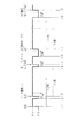
次に、制御用マイクロコンピュータ22の動作について説明する。図4は照明装置100の点灯状態の切り替えを示すタイミングチャートである。図4において、「2秒」、「10秒」が記載された矢印は、それぞれ2秒タイマ(オフ時間タイマ)、10秒タイマ(オン時間タイマ)がオンしている期間を示す。
Next, the operation of the
時刻t1で電源スイッチ2が操作されて電源がオン状態となり、照明装置100が点灯したとする。なお、時刻t1で点灯した際の調光モードは、いずれのものでもよいが、仮にモード1(80%調光)とする。時刻t1で10秒タイマ(オン時間タイマ)がセットされオンとなる。
It is assumed that the
次に、時刻t2で電源スイッチ2が操作されて電源がオフ状態となり、その後時刻t3で電源がオン状態になったとする。この場合、時刻t2で2秒タイマ(オフ時間タイマ)がセットされオンとなる。時刻t3において、直近の電源オンのタイミングである時刻t1でセットされた10秒タイマがオンであり、かつ2秒タイマがオンであるので、制御用マイクロコンピュータ22は、前回のモード(モード1)から遷移したモード(例えば、モード2)で各LEDモジュール30を点灯する。なお、時刻t3で10秒タイマ(オン時間タイマ)が一旦リセットされ、再度セットされオンとなる。
Next, it is assumed that the
次に、時刻t4で電源スイッチ2が操作されて電源がオフ状態となり、その後時刻t5で電源がオン状態になったとする。この場合、時刻t4で2秒タイマ(オフ時間タイマ)がセットされオンとなる。時刻t5において、直近の電源オンのタイミングである時刻t3でセットされた10秒タイマがオフであり、かつ2秒タイマがオンであるので、制御用マイクロコンピュータ22は、モードリセットして(例えば、モード0)で各LEDモジュール30を点灯する。なお、時刻t5で10秒タイマがセットされオンとなる。
Next, it is assumed that the
次に、時刻t6で電源スイッチ2が操作されて電源がオフ状態となり、その後時刻t7で電源がオン状態になったとする。この場合、時刻t6で2秒タイマ(オフ時間タイマ)がセットされオンとなる。時刻t7において、2秒タイマがオフであるので、直近の電源オンのタイミングである時刻t5でセットされた10秒タイマのオン/オフに関わらず、制御用マイクロコンピュータ22は、前回のモード(点灯前のモードであるモード0)で各LEDモジュール30を点灯する。なお、時刻t7で10秒タイマ(オン時間タイマ)が一旦リセットされ、再度セットされオンとなる。
Next, assume that the
次に、時刻t8で電源スイッチ2が操作されて電源がオフ状態となり、その後時刻t9で電源がオン状態になったとする。この場合、時刻t8で2秒タイマ(オフ時間タイマ)がセットされオンとなる。時刻t9において、2秒タイマがオフであるので、直近の電源オンのタイミングである時刻t7でセットされた10秒タイマのオン/オフに関わらず、制御用マイクロコンピュータ22は、前回のモード(点灯前のモードであるモード0)で各LEDモジュール30を点灯する。なお、時刻t9で10秒タイマがセットされオンとなる。以下、同様の動作を繰り返す。
Next, it is assumed that the
図5及び図6は照明装置100の動作状態と状態変化要因の関係を示す説明図である。図5及び図6において、横の欄は変更前の動作状態を示し、縦の欄は変化要因を示す。なお、図中、斜線で示す欄は、動作状態として存在しない場合を示す。例えば、最後(前回)の電源入り(オン)から10秒以上経過(10秒タイマオフ)し、電源切(オフ)から2秒以上経過(2秒タイマオフ)後に、電源入(オン)した場合、前回モードでLEDモジュール30が点灯するとともに、10秒タイマがオンする。
5 and 6 are explanatory diagrams showing the relationship between the operating state of the
また、最後(前回)の電源入り(オン)から10秒以上経過(10秒タイマオフ)し、電源切(オフ)から2秒以内(2秒タイマオン)後に、電源入(オン)した場合、モード0でLEDモジュール30が点灯(リセット動作)するとともに、10秒タイマがオンする。この場合、2秒タイマはオンのままである。また、最後(前回)の電源入り(オン)から10秒以上経過(10秒タイマオフ)し、電源切(オフ)から2秒以内(2秒タイマオン)であった状態で、最後の電源切から2秒以上経過した場合には、2秒タイマがオンからオフになる。
If the power is turned on (on) after 10 seconds have passed since the last (previous) power on (on) (10 seconds timer off) and within 2 seconds (2 seconds timer on) after power off (off), mode 0 Then, the
また、最後(前回)の電源入り(オン)から10秒以内(10秒タイマオン)で、電源切(オフ)から2秒以上経過(2秒タイマオフ)後に、電源入(オン)した場合、前回モードでLEDモジュール30が点灯する。また、最後(前回)の電源入り(オン)から10秒以内(10秒タイマオン)で、電源切(オフ)から2秒以上経過(2秒タイマオフ)後であった状態で、最後の電源入りから10秒以上経過した場合には、10秒タイマがオンからオフになる。
Also, when the power is turned on (on) within 10 seconds after the last (last time) power on (on) (10 second timer on) and more than 2 seconds have passed since power off (off) (2 seconds timer off), the previous mode As a result, the
また、最後(前回)の電源入り(オン)から10秒以内(10秒タイマオン)で、電源切(オフ)から2秒以内(2秒タイマオン)後に、電源入(オン)した場合、前回からモード遷移してLEDモジュール30が点灯する。また、最後(前回)の電源入り(オン)から10秒以内(10秒タイマオン)で、電源切(オフ)から2秒以内(2秒タイマオン)後であった状態で、最後の電源切から2秒以上経過した場合には、2秒タイマがオンからオフになる。さらに、最後(前回)の電源入り(オン)から10秒以内(10秒タイマオン)で、電源切(オフ)から2秒以内(2秒タイマオン)後であった状態で、最後の電源入りから10秒以上経過した場合には、10秒タイマがオンからオフになる。
Also, if the power is turned on (on) within 10 seconds after the last (previous) power on (10 seconds timer on), and within 2 seconds (2 seconds timer on) after power off (off), the mode is changed from the previous time. The
また、モード0でLEDモジュール30が点灯するとともに、2秒タイマ及び10秒タイマがいずれもオフの状態で、電源切(オフ)した場合、LEDモジュール30が消灯するとともに、2秒タイマがオンする。
In addition, when the
また、モード0でLEDモジュール30が点灯するとともに、2秒タイマがオフの状態であり、10秒タイマがオンの状態で、電源切(オフ)した場合、LEDモジュール30が消灯するとともに、2秒タイマがオンする。また、モード0でLEDモジュール30が点灯するとともに、2秒タイマがオフの状態であり、10秒タイマがオンの状態で、最後の電源入りから10秒以上経過した場合には、10秒タイマがオンからオフになる。
In addition, when the
また、モード0でLEDモジュール30が点灯するとともに、2秒タイマ及び10秒タイマがいずれもオンの状態で、電源切(オフ)した場合、LEDモジュール30が消灯する。また、モード0でLEDモジュール30が点灯するとともに、2秒タイマ及び10秒タイマがいずれもオンの状態で、最後の電源切から2秒以上経過した場合には、2秒タイマがオンからオフになる。また、モード1、2、3でLEDモジュール30が点灯している場合もモード0の場合と同様である。
In addition, the
図7は点灯状態の遷移状態を示す説明図である。図7に示すように、LEDモジュール30の点灯状態は、モード0(全灯)、モード1(80%調光)、モード2(50%調光)、モード3(25%調光)、消灯の5つのモードがある。なお、モードの数、調光の割合などは一例であって、これに限定されるものではない。また、モードの遷移順位は、モード0、モード1、モード2、モード3、モード0と巡回する。
FIG. 7 is an explanatory diagram showing the transition state of the lighting state. As shown in FIG. 7, the lighting state of the
図7に示すように、モードリセット操作の場合、すなわち、10秒タイマ(オン時間タイマ)がオフで、2秒タイマ(オフ時間タイマ)がオンの状態で電源入(オン)となった場合には、モード0でLEDモジュール30が点灯する。
As shown in FIG. 7, in the case of a mode reset operation, that is, when the power is turned on (on) with the 10-second timer (on-time timer) off and the 2-second timer (off-time timer) on. In the mode 0, the
また、モード変更操作の場合、すなわち、10秒タイマ(オン時間タイマ)がオンで、2秒タイマ(オフ時間タイマ)もオンの状態で電源入(オン)となった場合には、上述のモード遷移順位に従ってLEDモジュール30が点灯する。
Further, in the case of a mode change operation, that is, when the 10 second timer (on-time timer) is on and the 2-second timer (off-time timer) is also on, the power is turned on (on). The
また、前回モードで点灯操作を行った場合、すなわち、2秒タイマ(オフ時間タイマ)がオフの状態で電源入(オン)となった場合には、前回のモードと同じモードでLEDモジュール30が点灯する。
Further, when the lighting operation is performed in the previous mode, that is, when the power is turned on (on) with the 2-second timer (off time timer) being off, the
図8は制御用マイクロコンピュータ22の処理手順を示すフローチャートである。制御用マイクロコンピュータ(以下、「マイクロコンピュータ」という。)22は、電源スイッチがオン(入り)であるか否かを判定し(S11)、電源スイッチがオンでない場合(S11でNO)、ステップS11の処理を続ける。電源スイッチがオンである場合(S11でYES)、オフ時間タイマ(2秒タイマ)がオンであるか否かを判定する(S12)。
FIG. 8 is a flowchart showing a processing procedure of the
オフ時間タイマ(2秒タイマ)がオンでない場合(S12でNO)、すなわち、オフである場合、マイクロコンピュータ22は、前回のモードでLEDモジュール30を点灯する(S13)。オフ時間タイマ(2秒タイマ)がオンである場合(S12でYES)、マイクロコンピュータ22は、オン時間タイマ(10秒タイマ)がオンであるか否かを判定する(S14)。
If the off-time timer (2-second timer) is not on (NO in S12), that is, if it is off, the
オン時間タイマ(10秒タイマ)がオンである場合(S14でYES)、マイクロコンピュータ22は、モード遷移してLEDモジュール30を点灯し(S15)、オン時間タイマ(10秒タイマ)がオンでない場合(S14でNO)、すなわち、オフである場合、リセットモードでLEDモジュール30を点灯する(S16)。
When the on-time timer (10-second timer) is on (YES in S14), the
マイクロコンピュータ22は、オン時間タイマ(10秒タイマ)をセットする(S17)。なお、オン時間タイマがオンの状態であれば、一旦リセットして再度セット(オン)する。マイクロコンピュータ22は、電源スイッチがオフ(切)になったか否かを判定し(S18)、電源スイッチがオフでない場合(S18でNO)、ステップS18の処理を続ける。
The
電源スイッチがオフとなった場合(S18でYES)、マイクロコンピュータ22は、LEDモジュール30を消灯し(S19)、オフ時間タイマ(2秒タイマ)をセットし(S20)、ステップS11以降の処理を続ける。なお、オフ時間タイマがオンの状態であれば、一旦リセットして再度セット(オン)する。なお、上述の処理は、電源スイッチ2のオン/オフを判定し、判定結果に基づく処理を示しているが、基本的には無限ループの処理である。
When the power switch is turned off (YES in S18), the
以上説明したように、本発明にあっては、従来のように短時間の電源オフの操作を単に検出するだけでなく、電源のオン状態からオフ状態になるまでの経過時間を加味することにより、電源スイッチの入切操作だけで光源を所定の点灯状態(リセットモードでの点灯状態)にすることができ、複数の照明装置を1つの電源スイッチの入切で点灯制御する場合に、照明装置全体の点灯状態を所定の点灯状態に設定することができるので、仮に照明装置全体の調光レベルが同一にならない事態が発生した場合でもすべての照明装置の点灯状態、調光レベルを容易に揃えることができる。 As described above, in the present invention, not only simply detecting a short-time power-off operation as in the prior art, but also by taking into account the elapsed time from the power-on state to the off-state. When the light source can be brought into a predetermined lighting state (lighting state in the reset mode) only by turning on / off the power switch, and the lighting device is controlled by turning on / off one power switch, the lighting device Since the entire lighting state can be set to a predetermined lighting state, even if a situation occurs in which the dimming level of the entire lighting device is not the same, the lighting state and dimming level of all the lighting devices can be easily aligned. be able to.
また、天井等に設置された複数の照明装置を、個々にリモコンで、例えば調光レベルである照明状態を制御して、照明状態がまちまちになってしまう場合がある。その場合において、リモコンを用いて複数の照明装置の調光レベルを揃えるためには、1台1台の照明装置に対してリモコン操作が必要であるのに対し、本発明によれば、電源スイッチの入切操作で照明状態を容易に揃える(同期させる)ことができる。つまり、複数の照明装置の電源スイッチをオンにして所定の時間(本発明においては10秒間)経過した後に、電源スイッチの入切操作を所定の時間(本発明においては2秒間)内に行うことにより、複数の照明装置の各々の照明状態を容易に揃える(同期させる)ことができる。 In addition, there are cases where a plurality of lighting devices installed on the ceiling or the like are individually controlled by a remote controller, for example, to control the lighting state at the dimming level, and the lighting state becomes mixed. In that case, in order to align the dimming levels of a plurality of lighting devices using a remote controller, remote control operation is required for each lighting device, whereas according to the present invention, the power switch The lighting state can be easily aligned (synchronized) by the on / off operation. That is, after a predetermined time (10 seconds in the present invention) elapses after the power switches of a plurality of lighting devices are turned on, the power switch is turned on and off within a predetermined time (2 seconds in the present invention). Thus, it is possible to easily align (synchronize) the illumination states of the plurality of illumination devices.
また、上述の実施の形態では、複数の照明装置の点灯状態(全灯状態又は調光レベル)を揃える(同期させる)構成であったが、これに限定されるものではなく、複数の照明装置の光源の光色を揃える(同期させる)ようにすることもできる。 In the above-described embodiment, the lighting states (all lighting states or dimming levels) of a plurality of lighting devices are arranged (synchronized). However, the present invention is not limited to this, and a plurality of lighting devices is used. It is also possible to align (synchronize) the light colors of the light sources.
光色の異なる点灯状態としては、例えば、電球色、昼白色、昼光色等の異なる色温度の照明状態(点灯状態)でもよく、また、青色、緑色、赤色等の色度が異なる照明状態でもよい。複数の照明状態が、リモコン操作又はマイクロコンピュータのタイマのばらつきによって、各々異なる光色の照明状態になった場合であっても、複数の照明装置の電源スイッチをオンにして所定の時間(例えば10秒間)経過した後に、電源スイッチの入切操作を所定の時間(例えば2秒間)内に行うことにより、複数の照明装置の各々の照明状態を容易に揃える(同期させる)ことができる。 The lighting states with different light colors may be, for example, lighting states (lighting states) with different color temperatures such as light bulb color, daylight white, daylight color, or illumination states with different chromaticities such as blue, green, and red. . Even when the plurality of illumination states are in different illumination states due to remote control operations or microcomputer timer variations, the power switches of the plurality of illumination devices are turned on for a predetermined time (for example, 10). After the elapse of seconds, the lighting state of each of the plurality of lighting devices can be easily aligned (synchronized) by performing a power switch on / off operation within a predetermined time (for example, 2 seconds).
また、上述の実施の形態では、複数の照明装置のそれぞれに独立して個々の照明装置の点灯状態を制御する制御部であるマイクロコンピュータを備えているが、1つの照明装置に複数の光源部を備え、複数の光源部毎に各々の光源部を制御するマイクロコンピュータ等の制御部を有する照明装置であってもよい。この場合は、照明装置内部の複数の光源が異なる照明状態であっても、電源のスイッチの入切操作により照明状態を同期させることが可能となる。 In the above-described embodiment, each of the plurality of lighting devices includes a microcomputer that is a control unit that controls the lighting state of each lighting device independently. However, a plurality of light source units are included in one lighting device. And a lighting device having a control unit such as a microcomputer for controlling each light source unit for each of the plurality of light source units. In this case, even if a plurality of light sources in the illumination device are in different illumination states, the illumination states can be synchronized by turning on / off the power switch.
上述の実施の形態では、LEDモジュールそれぞれの電流を制御して調光する構成であったが、これに限定されるものではなく、一部のLEDモジュールを消灯することにより、照明装置全体の調光を行うようにしてもよい。 In the above-described embodiment, the dimming is performed by controlling the current of each LED module. However, the present invention is not limited to this, and the entire lighting device is dimmed by turning off some of the LED modules. You may make it perform light.
1 商用電源
2 電源スイッチ
10 電源ユニット
20 制御ユニット
21 制御電源供給回路
22 制御用マイクロコンピュータ
23 PWM制御回路
24 電源状態検出回路
25 メモリ
30 LEDモジュール
DESCRIPTION OF
Claims (4)
該各々の制御部は、
前記電源の入状態から切状態になるまでの第2経過時間が所定の時間を経過した場合、前記複数の光源の各々の点灯状態を所定の点灯状態に制御し、前記複数の光源の点灯状態を同期させることを特徴とする照明装置。 In each of the plurality of light sources, in a lighting device including a control unit that controls a lighting state of each of the plurality of light sources corresponding to a first elapsed time from a power-off state to an on state .
Each of the controllers is
When a second elapsed time from when the power is turned on to when the power is turned off has passed a predetermined time, the lighting state of each of the plurality of light sources is controlled to a predetermined lighting state, and the lighting states of the plurality of light sources are lighting device comprising a benzalkonium synchronize.
前記電源の切状態から入状態になるまでの第1経過時間を計時する第1計時部と、
前記電源の入状態から切状態になるまでの第2経過時間を計時する第2計時部と
を備え、
前記制御部は、
前記第2経過時間が第2閾値より長い場合において、前記第1経過時間が第1閾値より短いとき、前記複数の光源を所定の点灯状態に制御するように構成してあることを特徴とする請求項1に記載の照明装置。 A detector for detecting the ON state / OFF state of the power supply,
A first timer for measuring a first elapsed time from the power-off state to the on state;
A second timer for measuring a second elapsed time from when the power is turned on to when it is turned off;
The controller is
In the case where the second elapsed time is longer than a second threshold value, the plurality of light sources are controlled to be in a predetermined lighting state when the first elapsed time is shorter than the first threshold value. The lighting device according to claim 1 .
前記制御部は、
前記第2経過時間が前記第2閾値より短い場合において、前記第1経過時間が前記第1閾値より短いとき、直近の点灯状態から記憶した遷移情報に応じて遷移した点灯状態で前記複数の光源を点灯すべく制御するように構成してあることを特徴とする請求項2に記載の照明装置。 A storage unit for storing transition information between different lighting states of the plurality of light sources;
The controller is
When the second elapsed time is shorter than the second threshold and the first elapsed time is shorter than the first threshold, the plurality of light sources in the lighting state transitioned according to the transition information stored from the latest lighting state. the illumination device according to 請 Motomeko 2 you, characterized in that is arranged to control so as to light the.
前記第1経過時間が前記第1閾値より長い場合、直近の点灯状態で前記複数の光源を点灯すべく制御するように構成してあることを特徴とする請求項2又は請求項3に記載の照明装置。 The controller is
4. The configuration according to claim 2, wherein when the first elapsed time is longer than the first threshold, the plurality of light sources are controlled to be lit in the latest lighting state. 5. Lighting device .
Priority Applications (1)
| Application Number | Priority Date | Filing Date | Title |
|---|---|---|---|
| JP2008092572A JP5078706B2 (en) | 2008-03-31 | 2008-03-31 | Lighting device |
Applications Claiming Priority (1)
| Application Number | Priority Date | Filing Date | Title |
|---|---|---|---|
| JP2008092572A JP5078706B2 (en) | 2008-03-31 | 2008-03-31 | Lighting device |
Publications (3)
| Publication Number | Publication Date |
|---|---|
| JP2009245834A JP2009245834A (en) | 2009-10-22 |
| JP2009245834A5 JP2009245834A5 (en) | 2010-08-12 |
| JP5078706B2 true JP5078706B2 (en) | 2012-11-21 |
Family
ID=41307485
Family Applications (1)
| Application Number | Title | Priority Date | Filing Date |
|---|---|---|---|
| JP2008092572A Active JP5078706B2 (en) | 2008-03-31 | 2008-03-31 | Lighting device |
Country Status (1)
| Country | Link |
|---|---|
| JP (1) | JP5078706B2 (en) |
Cited By (1)
| Publication number | Priority date | Publication date | Assignee | Title |
|---|---|---|---|---|
| KR101780149B1 (en) * | 2016-06-03 | 2017-09-19 | 이앤에이치(주) | Led lighting apparatus having function of dimming |
Families Citing this family (10)
| Publication number | Priority date | Publication date | Assignee | Title |
|---|---|---|---|---|
| KR101216677B1 (en) * | 2011-04-14 | 2012-12-28 | 서영석 | A Controller of AC-DC Converter for LED lighting |
| JP2013084557A (en) * | 2011-07-21 | 2013-05-09 | Rohm Co Ltd | Luminaire |
| JP2013069501A (en) * | 2011-09-21 | 2013-04-18 | Panasonic Corp | Lighting device and illuminating device using the same |
| JP6105463B2 (en) * | 2013-12-25 | 2017-03-29 | 大光電機株式会社 | Lighting fixture pullless operation detection control device, lighting fixture including the detection control device, and lighting system |
| JP6281764B2 (en) * | 2014-02-14 | 2018-02-21 | パナソニックIpマネジメント株式会社 | Lamp and lighting device |
| US20170257916A1 (en) * | 2014-08-27 | 2017-09-07 | Sharp Kabushiki Kaisha | Lighting device |
| JP6534843B2 (en) * | 2015-03-31 | 2019-06-26 | コイズミ照明株式会社 | Lighting equipment and lighting system |
| KR101954168B1 (en) * | 2018-01-30 | 2019-03-05 | 주식회사 유니룩스 | Apparatus for Controlling Illuminance and Driving Method Thereof |
| CN112534180B (en) * | 2018-08-07 | 2024-08-09 | 三菱电机株式会社 | Lighting device and lighting unit |
| KR102048542B1 (en) * | 2018-08-30 | 2020-01-08 | 문재호 | Led lighting device driven by high efficiency and high reliabillty flicker free dimming converter including switch |
Family Cites Families (3)
| Publication number | Priority date | Publication date | Assignee | Title |
|---|---|---|---|---|
| JPH07282614A (en) * | 1994-04-14 | 1995-10-27 | Mitsubishi Rayon Co Ltd | Illuminating light source device |
| JPH10172784A (en) * | 1996-12-02 | 1998-06-26 | Meisho Rin | Electronic ballast light dimming method and device therefor |
| JP2007317483A (en) * | 2006-05-25 | 2007-12-06 | Matsushita Electric Works Ltd | Stream lighting type illumination system and control device used for same |
-
2008
- 2008-03-31 JP JP2008092572A patent/JP5078706B2/en active Active
Cited By (1)
| Publication number | Priority date | Publication date | Assignee | Title |
|---|---|---|---|---|
| KR101780149B1 (en) * | 2016-06-03 | 2017-09-19 | 이앤에이치(주) | Led lighting apparatus having function of dimming |
Also Published As
| Publication number | Publication date |
|---|---|
| JP2009245834A (en) | 2009-10-22 |
Similar Documents
| Publication | Publication Date | Title |
|---|---|---|
| JP5078706B2 (en) | Lighting device | |
| US10368421B2 (en) | Switching signal responding illumination device | |
| US20120032601A1 (en) | System for controlling a plurality of light sources | |
| KR101423403B1 (en) | Illumination device | |
| KR101124478B1 (en) | dimming control apparatus for LED lighting system that being adjustable illuminance | |
| CN103298202A (en) | Lighting system and lighting control device equipped for the lighting system | |
| JP2007073515A (en) | Multi-stage dimming control device and its dimming control method for gas discharge light | |
| US20130002147A1 (en) | Method of lighting intensity automatic adjustment and device with lighting intensity automatic adjustment | |
| US10638564B2 (en) | Retrofit light emitting diode, LED, tube for enabling step dimming in a multilamp luminaire lighting system | |
| JP2009289622A (en) | Lighting apparatus | |
| JP2013235655A (en) | Illumination lamp and lighting fixture | |
| WO2015065108A1 (en) | Smart led lighting device | |
| JP7186369B2 (en) | lighting equipment | |
| WO2016097929A1 (en) | Methods, systems and apparatus for emergency lighting. | |
| JP2006310258A (en) | Fluorescent lamp lighting device and lighting control system | |
| KR101698346B1 (en) | An ac wall switch performing led lights controls without supplemental power wires | |
| JP2006019244A (en) | Fluorescent lamp lighting device | |
| KR100993280B1 (en) | Led lamp having dimming funtion | |
| KR101402411B1 (en) | Gender for lighting | |
| US8829818B2 (en) | Control of operational parameters of operational devices for LEDs | |
| JP5126571B2 (en) | Light control device and light control system | |
| KR20160027469A (en) | Apparatus for controlling led lights without supplemental dimming wires and the control method thereof | |
| JP3193100U (en) | Uninterruptible power supply detection device | |
| RU134383U1 (en) | LED BRIGHTNESS CONTROL DEVICE | |
| KR20090001199U (en) | Illumination apparatus with Emergency Light function |
Legal Events
| Date | Code | Title | Description |
|---|---|---|---|
| A521 | Written amendment |
Free format text: JAPANESE INTERMEDIATE CODE: A523 Effective date: 20100624 |
|
| A621 | Written request for application examination |
Free format text: JAPANESE INTERMEDIATE CODE: A621 Effective date: 20100624 |
|
| A977 | Report on retrieval |
Free format text: JAPANESE INTERMEDIATE CODE: A971007 Effective date: 20120224 |
|
| A131 | Notification of reasons for refusal |
Free format text: JAPANESE INTERMEDIATE CODE: A131 Effective date: 20120313 |
|
| A521 | Written amendment |
Free format text: JAPANESE INTERMEDIATE CODE: A523 Effective date: 20120425 |
|
| A131 | Notification of reasons for refusal |
Free format text: JAPANESE INTERMEDIATE CODE: A131 Effective date: 20120626 |
|
| A521 | Written amendment |
Free format text: JAPANESE INTERMEDIATE CODE: A523 Effective date: 20120717 |
|
| TRDD | Decision of grant or rejection written | ||
| A01 | Written decision to grant a patent or to grant a registration (utility model) |
Free format text: JAPANESE INTERMEDIATE CODE: A01 Effective date: 20120807 |
|
| A01 | Written decision to grant a patent or to grant a registration (utility model) |
Free format text: JAPANESE INTERMEDIATE CODE: A01 |
|
| A61 | First payment of annual fees (during grant procedure) |
Free format text: JAPANESE INTERMEDIATE CODE: A61 Effective date: 20120828 |
|
| FPAY | Renewal fee payment (event date is renewal date of database) |
Free format text: PAYMENT UNTIL: 20150907 Year of fee payment: 3 |
|
| R150 | Certificate of patent or registration of utility model |
Ref document number: 5078706 Country of ref document: JP Free format text: JAPANESE INTERMEDIATE CODE: R150 Free format text: JAPANESE INTERMEDIATE CODE: R150 |