JP5076932B2 - Frame counter correction device and counter device - Google Patents
Frame counter correction device and counter device Download PDFInfo
- Publication number
- JP5076932B2 JP5076932B2 JP2008022465A JP2008022465A JP5076932B2 JP 5076932 B2 JP5076932 B2 JP 5076932B2 JP 2008022465 A JP2008022465 A JP 2008022465A JP 2008022465 A JP2008022465 A JP 2008022465A JP 5076932 B2 JP5076932 B2 JP 5076932B2
- Authority
- JP
- Japan
- Prior art keywords
- frame
- counter
- value
- inspection
- transmission
- Prior art date
- Legal status (The legal status is an assumption and is not a legal conclusion. Google has not performed a legal analysis and makes no representation as to the accuracy of the status listed.)
- Expired - Fee Related
Links
Images


Classifications
-
- H—ELECTRICITY
- H04—ELECTRIC COMMUNICATION TECHNIQUE
- H04L—TRANSMISSION OF DIGITAL INFORMATION, e.g. TELEGRAPHIC COMMUNICATION
- H04L43/00—Arrangements for monitoring or testing data switching networks
- H04L43/08—Monitoring or testing based on specific metrics, e.g. QoS, energy consumption or environmental parameters
- H04L43/0823—Errors, e.g. transmission errors
- H04L43/0847—Transmission error
Description
本発明は、イーサネット(登録商標)網に接続されたフレームカウンタ補正装置、対向装置及びフレームカウンタの補正方法に関する。 The present invention relates to a frame counter correction device, a counter device, and a frame counter correction method connected to an Ethernet (registered trademark) network.
従来、ネットワークインフラはSONET(Synchronous Optical Network)やSDH(Synchronous Digital Hierarchy)といった伝送方式により構築されてきたが、近年イーサネット技術をその代替とする動きがある。都市間のネットワークにイーサネットを適用しようとした場合、イーサネットはOAM(Operation Administration and Maintenance)機能が不十分であった。OAM機能とは、例えば、SONETの物理レイヤの障害管理、保守を行う機能である。 Conventionally, the network infrastructure has been constructed by a transmission method such as SONET (Synchronous Optical Network) or SDH (Synchronous Digital Hierarchy), but recently there is a movement to substitute Ethernet technology. When trying to apply Ethernet to networks between cities, Ethernet has insufficient OAM (Operation Administration and Maintenance) function. The OAM function is a function that performs failure management and maintenance of the SONET physical layer, for example.
特許文献1には、クライアントの測定パケットの送信タイミング、サーバが応答パケットを送信したタイミング、クライアントがその応答パケットを受信したタイミングを計測し、それらのデータに基づいてタイミングカウンタが計測するタイミングを補正することが記載されている。
In
非特許文献2には、ITU−T(International Telecommunication Union-Telecommunications Standardization Sector)のY.1731について記載されている。Y.1731は、イーサネット上でOAM機能を提供するために障害管理、保守管理の方法を規定したものである。
図1は、ITU−TのY.1731におけるポイントツーポイント接続の構成を示す図である。
以下の説明では、複数のME(Maintenance Entity)がポイントツーポイント接続されている場合に、同一管理境界内に存在するME群をMEG(ME Group)、OAMフレームを送信または終端するMEGの終点をMEP(MEG End Point)、特定のOAMフレーム中継、処理することができるMEGの中間点をMIP(MEGIntermediate Point)、MEGの管理レベルをMEG Levelと呼ぶ。
FIG. 1 is a diagram showing a configuration of point-to-point connection in ITU-T Y.1731.
In the following description, when a plurality of MEs (Maintenance Entity) are connected by point-to-point, ME groups existing within the same management boundary are defined as MEG (ME Group), and the end points of MEGs that transmit or terminate OAM frames are defined. MEP (MEG End Point), a specific OAM frame relay, an intermediate point of MEG that can be processed is called MIP (MEG Intermediate Point), and the management level of MEG is called MEG Level.
図1において、斜線の四角のブロックはMEPを示し、斜線の丸のブロックはMIPを示す。図1は、Customerの終点において、MEG Level7の障害管理を行う場合と、Providerの終点でMEG Level 7の障害管理を行う場合と、Operatorの終点で,MEG Level
5の障害監視を行う場合の例を示している。
In FIG. 1, hatched square blocks indicate MEP, and hatched circle blocks indicate MIP. FIG. 1 shows a case where MEG Level 7 failure management is performed at the Customer end point, a case where MEG Level 7 failure management is performed at the Provider end point, and the MEG Level at the Operator end point.
5 shows an example in which fault monitoring is performed.
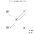
図2は、ITU−TのY.1731におけるマルチポイント接続の構成を示す図である。マルチポイント接続は、同一のフレームを受信する複数のMEからなるME群に対して適用され、マルチポイントを構成するグループは同一のMEGとして扱われる。 FIG. 2 is a diagram showing a configuration of multipoint connection in Y.1731 of ITU-T. The multipoint connection is applied to an ME group including a plurality of MEs that receive the same frame, and groups that constitute the multipoint are treated as the same MEG.
ここで、図3を参照して、MEPAからMEPBに検査フレームを送信してフレームロスを計算する場合について説明する。
送信側のMEPAと受信側のMEPBは、フレームの通過数をカウントする送信カウンタと受信カウンタを有する。
Here, with reference to FIG. 3, a case where a frame loss is calculated by transmitting a test frame from MEPA to MEPB will be described.
The MEPA on the transmission side and the MEPB on the reception side have a transmission counter and a reception counter that count the number of passing frames.
送信側のMEPAは、検査フレームを作成するときに、送信カウンタからカウンタ値A1を取得し、そのカウンタ値A1を検査フレームに書き込み送信する。受信側のMEPBは、検査フレームを受信すると、受信カウンタからそのときのカウンタ値B1を取得する
。上記の動作が2回繰り返されて、受信側のMEPBは、2つの送信カウンタ値A1、A2と、2つの受信カウンタ値B1、B2を得る。こられらのカウンタ値から、以下の式によりフレームロスを計算することができる。
When the MEPA on the transmission side creates an inspection frame, it acquires the counter value A1 from the transmission counter, writes the counter value A1 in the inspection frame, and transmits it. When receiving the test frame, the MEPB on the receiving side acquires the counter value B1 at that time from the reception counter. The above operation is repeated twice, and the receiving MEPB obtains two transmission counter values A1 and A2 and two reception counter values B1 and B2. From these counter values, the frame loss can be calculated by the following equation.
フレームロス数=(送信カウンタ値A2−送信カウンタ値A1)−(受信カウンタ値B2−受信カウンタ値B1)
図4は、フレームロスの計測の問題点の説明図である。図4は、(a)送信カウンタの読み取り処理、(b)検査フレームの作成処理、(c)検査フレームの送信処理を時系列に並べたものである。
Number of frame losses = (transmission counter value A2−transmission counter value A1) − (reception counter value B2−reception counter value B1)
FIG. 4 is an explanatory diagram of the problem of frame loss measurement. FIG. 4 shows (a) transmission counter reading processing, (b) inspection frame creation processing, and (c) inspection frame transmission processing arranged in time series.
送信カウンタの値を読み取ってから検査フレームの生成が完了するまでには一定の処理時間が掛かかるので、その間通常フレームを受信して、その通常フレームが送信されると、送信カウンタの値がインクリメントされてしまう。図4は、送信カウンタの値を読み取ってから実際に検査フレームが送信されるまでの間に、5個の通常フレームが通過する場合の例を示している。 Since it takes a certain amount of processing time to complete generation of the inspection frame after reading the value of the transmission counter, when the normal frame is received and the normal frame is transmitted during that time, the value of the transmission counter is incremented. Will be. FIG. 4 shows an example in which five normal frames pass from when the value of the transmission counter is read to when the test frame is actually transmitted.
その結果、受信側のMEPBにおいては、検査フレームを受信したときの受信カウンタの値が期待値(検査フレームに書き込まれているカウンタ値A1)より「5」大きな値が計測されることになる。つまり、この場合の受信カウンタの値B2は、B2=A1+5となる。前述した式からフレームロスを計算すると、フレームロス=(A2−A1)−(B2+5−B1)、となり、B1=A1が期待値であるから、フレームロスは、次のような値となる。フレームロス=(A2−A1)−(A2+5−A1)=−5
このようにフレームロスが負の値となり、フレームロスの計測に誤りが生じる。上記の問題は、以下のような場合に顕著になる。
(1)検査フレームの生成部と検査フレームの送信部が別のハードウェアで構成され、ハードウェアのバスの性能が内部アーキテクチャに依存する場合。
(2)検査フレームの生成部が低廉なプロセッサで構成され、検査フレームの生成に時間が掛かる場合。
(3)検査フレームの生成と検査フレームの送信がソフトウェアで構成されているために、処理速度に限界がある場合。
(4)送信カウンタがハードウェアで構成され、検査フレームの生成がソフトウェアで構成されている場合。API(Application Program Interface)を経由することにより、送信カウンタの値の読み出し速度が遅くなる。
As a result, in the MEPB on the receiving side, the value of the reception counter when the test frame is received is measured by a value “5” larger than the expected value (counter value A1 written in the test frame). That is, the value B2 of the reception counter in this case is B2 = A1 + 5. When the frame loss is calculated from the above formula, frame loss = (A2−A1) − (B2 + 5−B1), and B1 = A1 is an expected value, so the frame loss is as follows. Frame loss = (A2-A1)-(A2 + 5-A1) =-5
Thus, the frame loss becomes a negative value, and an error occurs in the measurement of the frame loss. The above problem becomes prominent in the following cases.
(1) The case where the test frame generation unit and the test frame transmission unit are configured by different hardware, and the performance of the hardware bus depends on the internal architecture.
(2) The case where the inspection frame generation unit is configured with an inexpensive processor and it takes time to generate the inspection frame.
(3) When the processing speed is limited because the generation of the inspection frame and the transmission of the inspection frame are configured by software.
(4) The transmission counter is configured by hardware, and the generation of the inspection frame is configured by software. By going through an API (Application Program Interface), the reading speed of the value of the transmission counter becomes slow.
上記の問題は、送信カウンタの値を読み取ってから検査フレームを送信するまでの間、通常フレームをバッファに保存しておくことで回避することができる。
しかしながら、その方法では、通常フレームの伝送遅延が大きくなり、通信速度が低下してしまう。
However, with this method, the transmission delay of normal frames increases, and the communication speed decreases.
本発明の課題は、フレームロスの計測を正確に行えるようにすることである。 An object of the present invention is to enable accurate measurement of frame loss.
フレームカウンタ補正装置は、イーサネット網に接続されるフレームカウンタ補正装置であって、送信するフレーム数をカウントする送信カウンタ手段と、フレームロスを計測するための検査フレームを生成する検査フレーム生成手段と、前記検査フレームの生成時
の前記送信カウンタ手段のカウント値と、前記検査フレームの送信時の前記送信カウンタ手段のカウント値の差分を算出し、算出した差分値と補正対象の検査フレームを特定する情報を別の検査フレームに付加する送信カウンタ補正手段とを備える。
The frame counter correction apparatus is a frame counter correction apparatus connected to the Ethernet network, and includes a transmission counter means for counting the number of frames to be transmitted, a test frame generation means for generating a test frame for measuring a frame loss, Information for calculating the difference between the count value of the transmission counter means at the time of generating the inspection frame and the count value of the transmission counter means at the time of transmitting the inspection frame, and identifying the calculated difference value and the inspection frame to be corrected Transmission counter correction means for adding to the other inspection frame.
このフレームカウンタ補正装置によれば、検査フレームのカウンタ値を正しく補正できるので、受信側で正確にフレームロスを計測できる。
上記のフレームカウンタ補正装置において、前記送信カウンタ補正手段は、補正対象の検査フレームのシーケンス番号と前記差分値を、Y.1731で規定されるCCフレームの予備領域に挿入する。
According to this frame counter correction device, the counter value of the inspection frame can be corrected correctly, so that the frame loss can be accurately measured on the receiving side.
In the above frame counter correction device, the transmission counter correction means calculates the sequence number of the inspection frame to be corrected and the difference value as Y.P. It is inserted into the spare area of the CC frame defined by 1731.
このように構成することで、Y.1731のCCフレームにカウンタ値の補正に必要な情報を付加して送信することができる。
上記のフレームカウンタ補正装置において、前記送信カウンタ手段は、前記検査フレームの生成が終了した時点でカウンタ値の読み取りをロックし、前記検査フレームの送信が完了した時点でロックを解除する。
By configuring in this way, Y.M. Information necessary for correction of the counter value can be added to the 1731 CC frame and transmitted.
In the frame counter correction apparatus, the transmission counter unit locks reading of the counter value when the generation of the inspection frame is completed, and releases the lock when transmission of the inspection frame is completed.
このように構成することで、検査フレームの生成が終了してその検査フレームが送信されるまでの間、カウンタ値の読み取りをロックすることで、カウンタ値の誤差を減らすことができる。
With this configuration, the counter value error can be reduced by locking the reading of the counter value until generation of the test frame is completed and the test frame is transmitted.
上記のフレームカウンタ補正装置において、フレーム受信手段と、受信フレーム数をカウントする受信カウンタ手段と、検査フレームを受信したときの前記受信カウンタのカウンタ値と、別の検査フレームに付加されて送信されてくる、補正対象の検査フレームを特定する情報と、補正対象の検査フレームのカウンタ値の差分値を取得する取得手段と、前記取得手段により取得した、補正対象の検査フレームを特定する情報に基づいて該当する検査フレームを特定し、特定した検査フレームのカウンタ値を前記差分値に基づいて補正すると共に、補正したカウント値と前記受信カウンタ手段のカウント値に基づいてフレームロスを計測するフレームロス計測手段とを備える。 In the above frame counter correction device, the frame reception means, the reception counter means for counting the number of received frames, the counter value of the reception counter when the inspection frame is received, and added to another inspection frame are transmitted. Based on the information for specifying the inspection frame to be corrected, the acquisition means for acquiring the difference value of the counter value of the inspection frame to be corrected, and the information for specifying the inspection frame to be corrected acquired by the acquisition means Frame loss measuring means for identifying a corresponding inspection frame, correcting the counter value of the specified inspection frame based on the difference value, and measuring the frame loss based on the corrected count value and the count value of the reception counter means With.
このように構成することで、対向装置から送信されてくる検査フレームのカウント値を補正し、フレームロスを正確に計測することができる。
対向装置は、イーサネット網に接続された他の装置から送信されるフレームを受信する対向装置であって、フレーム、前記フレーム受信手段で受信したフレーム数をカウントする受信カウンタ手段と、検査フレームを受信したときの前記受信カウンタのカウンタ値と、別の検査フレームに付加されて送信されてくる、補正対象の検査フレームを特定する情報と、補正対象の検査フレーム生成時の送信側の送信カウンタ手段のカウンタ値と補正対象の検査フレームの送信時のカウンタ値の差分値を取得する取得手段と、前記取得手段により取得した、補正対象の検査フレームを特定する情報に基づいて該当する検査フレームを特定し、特定した検査フレームのカウンタ値を前記差分値に基づいて補正すると共に、補正したカウント値と前記受信カウンタ手段のカウント値に基づいてフレームロスを計測する送受信カウンタ管理手段とを備える。
With this configuration, it is possible to correct the count value of the inspection frame transmitted from the opposite device and accurately measure the frame loss.
The counter device is a counter device that receives a frame transmitted from another device connected to the Ethernet network, and receives a test frame and a reception counter unit that counts the number of frames received by the frame reception unit. The counter value of the reception counter at the time of transmission, information specifying the inspection frame to be corrected that is added to another inspection frame and transmitted, and transmission counter means on the transmission side when generating the inspection frame to be corrected An acquisition unit that acquires a difference value between a counter value and a counter value at the time of transmission of an inspection frame to be corrected, and a corresponding inspection frame that is acquired based on information that is acquired by the acquisition unit and that specifies the inspection frame to be corrected. The counter value of the specified inspection frame is corrected based on the difference value, and the corrected count value and the reception And a reception counter management means for measuring a frame loss based on the count value of the counter means.
この対向装置によれば、検査フレームのカウント値を補正してフレームロスを正確に計測することができる。 According to this opposing device, the frame loss can be accurately measured by correcting the count value of the inspection frame.
開示のフレームカウンタ補正装置によれば、検査フレームのカウンタ値を正しい値に補正することができる。これにより受信側で、フレームロスを正確に計測することができる。 According to the disclosed frame counter correction apparatus, the counter value of the inspection frame can be corrected to a correct value. As a result, the frame loss can be accurately measured on the receiving side.
以下、本発明の好適な実施の形態について説明する。図6は、第1の実施の形態のフレームカウンタ補正装置20の構成を示す図である。
以下に説明する実施の形態は、イーサネットを用いた基幹通信において、ITU−TのY.1731に基づいたOAM(Operation Administration and Maintenance)機能を提供するものである。第1の実施の形態のフレームカウンタ補正装置20は、図1または図2のME(Maintenance Entity)に内蔵される。
Hereinafter, preferred embodiments of the present invention will be described. FIG. 6 is a diagram illustrating a configuration of the frame
The embodiment described below provides an OAM (Operation Administration and Maintenance) function based on ITU-T Y.1731 in backbone communication using Ethernet. The frame
フレームカウンタ補正装置20は、フレーム処理部21、検査フレーム生成部22、スケジューラ23、フレーム識別部24、送信カウンタ25、フレーム送信部26、カウンタ差分管理部27からなる。これらのブロックは、ハードウェアで構成しても良いし、ソフトウェアで構成しても良い。
The frame
通常フレーム処理部21は、通常フレームに対する処理を行い、処理結果をスケジューラ23に出力する。検査フレーム生成部22は、一定期間毎、または指示されたタイミングで、検査フレームを生成してスケジューラ23に出力する。検査フレーム生成部22は、検査フレームを生成する際に、送信カウンタ25の値を読み出し、そのカウンタ値と検査フレームを特定するシーケンス番号を検査フレームに書き込む。さらに、検査フレーム生成部22は、送信カウンタ25から読み出したカウンタ値をカウンタ差分管理部27に出力する。
The normal
スケジューラ23は、通常フレームと検査フレームをスケジューリングしてフレーム識別部24に出力する。
フレーム識別部24は、受信したフレームが、検査フレームか、通常フレームかを識別し、通常フレームであれば送信カウンタ25をインクリメントして、受信したフレームをフレーム送信部26に出力する。また、受信したフレームが検査フレームであれば、送信カウンタ25の値を読み出し、読み出したカウンタ値をカウンタ差分管理部27に出力すると共に検査フレームをフレーム送信部26に出力する。
The
The
カウンタ差分管理部27は、検査フレーム生成時の送信カウンタ25の値と、検査フレーム送信時の送信カウンタ25の値の差分を算出し、差分がある場合には、その差分値と、補正対象の検査フレームを特定する情報(例えば、シーケンス番号)を検査フレーム生成部22に出力する。これにより、検査フレーム生成部22は、補正対象の検査フレームを特定する情報と差分値を含む検査フレームを作成することができる。カウンタ差分管理部27と、検査フレーム生成部22の一部の機能は、送信カウンタ補正手段に対応する。
The counter
フレーム送信部26は、通常フレームと検査フレームをイーサネットのネットワークに送出する。
図7は、フレームカウンタ補正装置20のフレーム識別部24の処理動作を示すフローチャートである。
The
FIG. 7 is a flowchart showing the processing operation of the
フレーム識別部24は、送信元MAC(Media Access Control)アドレスが自己のMACアドレスと一致する否かを判定し(図7、S11)、不一致の場合には、ステップS12に進み、送信カウンタ25をインクリメントする。そして、受信したフレームをフレーム送信部26に出力する(S13)。
The
送信元MACアドレスが自己のMACアドレスと一致する場合には、検査フレームか否かを判定する。受信したフレームが検査フレームの場合には(S11、YES)、ステップS14に進み、送信カウンタ25の値を読み出す。そして、読み出した送信カウンタ25の値をカウンタ差分管理部27に通知する(S15)。その後、ステップS13におい
て、検査フレームをフレーム送信部26に出力する。
If the source MAC address matches its own MAC address, it is determined whether or not it is an inspection frame. When the received frame is an inspection frame (S11, YES), the process proceeds to step S14, and the value of the
図8は、フレームカウンタ補正装置20の処理シーケンスを示す図である。検査フレーム生成部22は、検査フレームを生成するときに、送信カウンタ25の値(例えば、A)を読み出す。そして、検査フレームを生成し、その検査フレーム固有のシーケンス番号と送信カウンタ25のカウンタ値を検査フレームに格納する。さらに、検査フレーム生成部22は、生成した検査フレームのシーケンス番号と送信カウンタ25の値をカウンタ差分管理部27に出力する。
FIG. 8 is a diagram showing a processing sequence of the frame
検査フレーム生成部22において検査フレームが生成される間に通常フレームを受信した場合には、通常フレーム処理部21は、受信した通常フレーム(この場合、3個の通常フレーム)をフレーム送信部26に出力する。図8の例では、データフレーム1から3の3個のフレームがフレーム送信部26に出力される。
When the normal frame is received while the test frame is generated in the test
検査フレーム生成部22が検査フレーム(例えば、シーケンス番号1、カウンタ値A)をフレーム識別部24に送出すると、フレーム識別24は、受信したフレームが、検査フレームか、通常フレームかを識別し、通常フレームのときには、送信カウンタ25にカウンタ値をインクリメントする指示を与える。また、検査フレームと判断したときには、送信カウンタ25のカウンタ値を読み出し、読み出したカウンタ値を検査フレームのシーケンス番号と共にカウンタ差分管理部27に出力する。これらの処理が終わると、フレーム識別部24は、検査フレームをフレーム送信部26に出力する。
When the test
なお、送信カウンタ25は、フレーム識別部24からカウンタ値を読み出された時点で読み出しをロックし、検査フレームの送信が終了した時点でロックを解除するようにしても良い。
The
カウンタ差分管理部27は、同一のシーケンス番号と対応付けられた2つのカウンタ値(例えば、A、B)を受信すると、それらの差分を算出し、算出した差分値をシーケンス番号と対応付けてメモリ等に格納する。
When the counter
検査フレーム生成部22は、次の検査フレームを生成するときに、送信カウンタ25のカウント値を読み出し、検査フレームのシーケンス番号と読み出したカウント値をカウンタ差分管理部27に出力する。
When the next test frame is generated, the test
カウンタ差分管理部27は、送信済みの検査フレームのシーケンス番号と、カウンタ値の差分を検査フレーム生成部22に出力する。
検査フレーム生成部22は、カウント値の差分が存在する場合には、次の検査フレームに、補正対象の検査フレームのシーケンス番号とその補正値を付加してスケジューラ23に出力する。
The counter
When there is a difference in the count value, the test
このように補正対象の検査フレームのシーケンス番号と差分値を書き込んだ検査フレームを送信することで、受信側の対向装置では、検査フレームに付加されている補正対象のシーケンス番号から補正対象の検査フレームを特定し、その検査フレームのカウンタ値の補正値を取得して補正対象の検査フレームのカウント値を補正することができる。これにより、受信側の対向装置においては、検査フレームを受信したときの受信カウンタの値と、その検査フレームの補正したカウンタ値に基づいてフレームロスを正確に計測することができる。 In this way, by transmitting the inspection frame in which the sequence number and the difference value of the inspection frame to be corrected are written, the receiving-side counter device allows the inspection frame to be corrected from the correction target sequence number added to the inspection frame. And the correction value of the counter value of the inspection frame is acquired, and the count value of the inspection frame to be corrected can be corrected. As a result, the receiving-side counter device can accurately measure the frame loss based on the value of the reception counter when the inspection frame is received and the counter value corrected for the inspection frame.
ここで、OAMのPDU共通フォーマットと検査フレームのフレームフォーマットについて説明する。
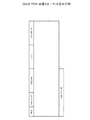
図9は、OAM PDU(Protocol Data Unit)の共通フォーマットを示す図である。
Here, the OAM PDU common format and the frame format of the inspection frame will be described.
FIG. 9 is a diagram showing a common format of OAM PDU (Protocol Data Unit).
OAM PDU共通フォーマットには、EEG Level、バージョン、PDUのタイプを示すオペコード、TLV(Type, Length, and Value)オフセット等が格納される。
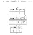
図10は、CC(Continuity Check)フレームのフォーマットを示す図である。
The OAM PDU common format stores an EEG Level, a version, an operation code indicating a PDU type, a TLV (Type, Length, and Value) offset, and the like.
FIG. 10 is a diagram showing a format of a CC (Continuity Check) frame.
CCフレームは、MEL、バージョン(0)、オペコード(CCM=1)、フラグ、TLVオフセット、シーケンス番号、MEP ID、MEG ID、TxFCf、RxFCb、TxFCb等からなる。シーケンス番号は通常「0」が設定される。 The CC frame includes MEL, version (0), operation code (CCM = 1), flag, TLV offset, sequence number, MEP ID, MEG ID, TxFCf, RxFCb, TxFCb, and the like. The sequence number is normally set to “0”.
MEP IDには、CCフレームを送信するフレーム補正装置21のIDが格納され、TxFCf、RxFCb、TxFCbにはCCフレームにより通知するカウンタ値が格納される。
The MEP ID stores the ID of the
図11は、実施の形態のCCフレーム(検査フレーム)の計測フォーマットを示す図である。図10のCCフレームとの違いは、シーケンス番号が格納される領域に「0」以外の値が格納され、予備領域(Reserved)に補正対象の検査フレームのシーケンス番号と、補正値(差分値)が格納される点である。 FIG. 11 is a diagram illustrating a measurement format of the CC frame (inspection frame) according to the embodiment. The difference from the CC frame of FIG. 10 is that a value other than “0” is stored in the area where the sequence number is stored, and the sequence number of the inspection frame to be corrected and the correction value (difference value) in the reserved area (Reserved). Is the point where is stored.
図11のCCフレームのシーケンス番号としては、1、2、3・・・と順にインクリメントされた値が格納される。予備領域には、補正対象の検査フレームのシーケンス番号(Corrected Sequence Number)と、カウンタ値の差分値(Corrected TxFCf)が格納される。受信側では、この予備領域に格納されているシーケンス番号と差分値とから、どの検査フレームのカウント値を補正するかを知ることができる。 As the sequence number of the CC frame in FIG. 11, values incremented in order of 1, 2, 3,... Are stored. In the spare area, the sequence number (Corrected Sequence Number) of the inspection frame to be corrected and the difference value (Corrected TxFCf) between the counter values are stored. On the receiving side, it is possible to know which inspection frame count value is to be corrected from the sequence number and the difference value stored in the spare area.
次に、図12は、実施の形態の対向装置(MEP)の構成を示す図である。対向装置31は、フレーム受信部32と、フレーム識別部33と、受信カウンタ34と、スケジューラ35と、送信/受信カウンタ管理36と、フレーム処理部37と、検査フレーム解析部38とを備える。これらのブロックは、ハードウェアで構成しても良いし、一部または全部をソフトウェアで構成しても良い。
Next, FIG. 12 is a diagram illustrating a configuration of a counter apparatus (MEP) according to the embodiment. The opposing
フレーム受信部32は、受信したフレームをフレーム識別部33に出力する。フレーム識別33は、受信したフレームが通常フレームか、検査フレームかを識別し、通常フレームを受信した場合には、受信カウンタ34にカウント値をインクリメントする指示を与え、受信した通常フレームをスケジューラ35に出力する。また、検査フレームを受信した場合には、受信カウンタ34のカウント値を読み取り、読み取ったカウント値と処理IDを対応付けて送信/受信カウンタ管理部36に出力すると共に、処理IDと共に検査フレームをスケジューラ35に出力する。
The
スケジューラ35は、通常フレームをフレーム処理部37に出力し、検査フレームを処理IDと共に検査フレーム解析部38に出力する。
検査フレーム解析部(取得手段に対応する)38は、検査フレームのシーケンス番号(及び補正対象のシーケンス番号)と送信カウンタ値を取得し、それらのデータを処理IDと共に送信/受信カウンタ管理部36に出力する。
The
The inspection frame analysis unit (corresponding to the acquisition unit) 38 acquires the sequence number (and the correction target sequence number) of the inspection frame and the transmission counter value, and sends the data to the transmission / reception counter management unit 36 together with the process ID. Output.
送信/受信カウンタ管理部(送受信カウンタ管理手段に対応する)36は、検査フレームに格納されている送信カウンタ値と、フレーム識別部33から出力された受信カウンタ値を対応付けてデータベースに格納する。なお、送信/受信カウンタ管理部36での送信カウンタ値と受信カウンタ値の対応付けは、フレーム識別部33が検査フレームの到着時に発行する処理IDを用いて行う。
The transmission / reception counter management unit (corresponding to the transmission / reception counter management unit) 36 stores the transmission counter value stored in the examination frame and the reception counter value output from the
また、送信/受信カウンタ管理部36は、次の検査フレームの受信カウンタ値、シーケンス番号及び補正対象の検査フレームのシーケンス番号、カウンタ値の差分値を取得すると、データベースに記憶してある同一のシーケンス番号の受信カウンタ値、送信カウンタ値を読み出し、それらのデータを用いて該当する検査フレームの送信カウンタ値を補正する。これにより、正しい送信カウンタ値と受信カウンタ値の対を記憶することができ、それらのカウンタ値からフレームロスを正確に計測することができる。 When the transmission / reception counter management unit 36 acquires the reception counter value of the next inspection frame, the sequence number, the sequence number of the inspection frame to be corrected, and the difference value of the counter value, the same sequence stored in the database is obtained. The reception counter value and the transmission counter value of the number are read out, and the transmission counter value of the corresponding inspection frame is corrected using those data. Thereby, a pair of correct transmission counter value and reception counter value can be stored, and frame loss can be accurately measured from these counter values.
図13は、対向装置31のフレーム識別部33の処理動作を示すフローチャートである。
フレーム識別部33は、受信したフレームの宛先MACアドレスを識別し(図13、S21)、宛先MACアドレスが自装置のMACアドレスでない場合には(S21、NO)、ステップS22に進み、受信カウンタ34をインクリメントし、受信したフレームをスケジューラ35に出力する。スケジューラ35に出力されたフレームは、通常のフレーム処理が行われる(S23)。
FIG. 13 is a flowchart showing the processing operation of the
The
宛先MACアドレスが自装置のMACアドレスと一致した場合には、そのフレームか検査フレームか否かを判定する。検査フレームであった場合には(S21、YES)、ステップS24に進み、そのときの受信カウンタ34の値を読み出し、そのカウンタ値を処理IDと共に送信/受信カウンタ管理部36に出力する。また、検査フレームを処理IDと共に検査フレーム解析部38に出力する(S25)。
When the destination MAC address matches the MAC address of the own device, it is determined whether the frame is the inspection frame or not. If it is an inspection frame (S21, YES), the process proceeds to step S24, the value of the
図14は、検査フレーム解析部38の処理動作を示すフローチャートである。検査フレーム解析部38は、受信したフレームがCCフレームか否かを判定する(図14、S31)。CCフレームであったときには(S31、YES)、ステップS32に進み、検査フレームにシーケンス番号が格納されているか否かを判定する。
FIG. 14 is a flowchart showing the processing operation of the inspection
シーケンス番号が格納されている場合には(S32、YES)、ステップS33に進み、さらに検査フレームに補正シーケンス番号が格納されているか否かを判定する。
補正シーケンス番号が格納されていない場合には(S33、NO)、ステップS34に進み、検査フレームに格納されている、フレームカウンタ補正装置20の送信カウンタ値と対向装置31の受信カウンタ値を取得し、それらのデータを処理IDと対応付けてメモリ等の記憶装置に格納する。
When the sequence number is stored (S32, YES), the process proceeds to step S33, and it is further determined whether or not the correction sequence number is stored in the inspection frame.
When the correction sequence number is not stored (S33, NO), the process proceeds to step S34, and the transmission counter value of the frame
他方、検査フレームに補正シーケンス番号が格納されている場合には(S33、YES)、ステップS35に進み、検査フレームに格納されている、フレームカウンタ補正装置20の送信カウンタ値と、対向装置31の受信カウンタ値を取得し、それらのデータを処理IDと対応付けて記憶装置に格納する。さらに、シーケンス番号をキーとするエントリをデータベースに追加し、そのエントリの中で補正シーケンス番号と一致するシーケンス番号のデータを、検査フレームの補正値(カウンタ値の差分)に基づいて書き換える。
On the other hand, when the correction sequence number is stored in the inspection frame (S33, YES), the process proceeds to step S35, the transmission counter value of the frame
図15は、対向装置31の処理シーケンスを示す図である。フレーム識別部33は、検査フレームを受信すると、受信カウンタ34のカウンタ値を読み出し、読み出したカウンタ値(例えば、C)に処理IDを付与して送信/受信カウンタ管理部36に出力する。
FIG. 15 is a diagram illustrating a processing sequence of the opposing
図15の処理シーケンスは、検査フレーム解析部38において検査フレームを解析している間に、データフレーム1〜3がフレーム受信部32で受信され、受信カウンタ34の値がその分インクリメントされた場合を示している。
The processing sequence of FIG. 15 shows a case where data frames 1 to 3 are received by the
検査フレーム解析部38は、検査フレームからシーケンス番号、送信カウンタ値及びそ
の他のパラメータを抽出し、それらのデータを処理IDと共に送信/受信カウンタ管理部36に出力する。また、検査フレーム解析部38は、検査フレームから補正シーケンス番号と送信カウンタ値の差分値を抽出し、それらのデータを処理IDと共に送信/受信カウンタ管理部36に出力する。補正シーケンス番号と差分値は、例えば、図11のCCフレームの予備領域に格納されている。
The inspection
送信/受信カウンタ管理部36は、検査フレーム解析部38から受け取った処理IDとシーケンス番号と送信カウンタ値と、フレーム識別部33から受け取った処理IDと受信カウンタ値(例えば、C)を、処理IDにより対応付けてデータベースに登録する。
The transmission / reception counter management unit 36 uses the process ID, sequence number, transmission counter value received from the examination
送信/受信カウンタ管理部36は、検査フレーム解析部38から別の検査フレームの補正シーケンス番号と差分値を受け取った場合には、補正シーケンス番号と一致するシーケンス番号の送信カウンタ値に差分値を加算し、加算結果をそのシーケンス番号の補正後のカウンタ値としてメモリに格納する。
When the transmission / reception counter management unit 36 receives the correction sequence number and the difference value of another inspection frame from the inspection
これにより、フレームカウンタ補正装置20から送出される検査フレームの送信カウンタ値を、そのフレームカウンタ補正装置20を実際に通過したフレーム数に応じて補正することができる。従って、受信側では、到達した検査フレームの送信カウンタ値と補正値と受信カウンタ値からフレームロスを正確に計測することができる。
Thereby, the transmission counter value of the inspection frame transmitted from the frame
上述した第1の実施の形態によれば、検査フレームを送信するまでの間に通常フレームがフレームカウンタ補正装置20を通過する場合でも、補正対象の検査フレームを特定する情報(例えば、シーケンス番号)と、検査フレームのカウント値を補正するための補正値を別の検査フレームに付加して送信することで、受信側では、それらの情報に基づいて検査フレームに格納されているカウント値を正しい値に補正することができる。これにより、検査フレームのカウント値と、対向装置31の受信カウンタ34のカウント値からフレームロスを正確に計測することができる。
According to the first embodiment described above, even when a normal frame passes through the frame
次に、第2の実施の形態について説明する。第2の実施の形態は、フレームカウンタ補正装置41が、カウンタ値の差分値を含む検査フレームを対向装置42に送信し、対向装置51が、受信した検査フレームのシーケンス番号と自装置におけるカウンタ値の差分値を含む検査フレームをフレームカウンタ補正装置41に送信することで、フレームカウンタ補正装置41と対向装置42の双方がフレームロスを計測できるようにしたものである。
Next, a second embodiment will be described. In the second embodiment, the frame counter correction device 41 transmits an inspection frame including the difference value of the counter value to the
フレームカウンタ補正装置41の構成は図示していないが、図6に示すフレームカウンタ補正装置20と同じ検査フレームの送信機能と、図12の対向装置31の検査フレームを受信する機能(受信カウンタ34、検査フレーム解析部38など)並びにパケットロスを計測する機能を有している。また、対向装置42は、図12の対向装置31と同じ検査フレームの受信機能とパケットロスを計測する機能と、図6に示すフレームカウンタ補正装置20の検査フレームの送信機能(送信カウンタ25、カウンタ差分管理部27など)を有する。以下、図6と図12に示したものと同じ回路ブロックには同じ符号を付けて説明を行う。
Although the configuration of the frame counter correction device 41 is not shown, the same inspection frame transmission function as that of the frame
図16は、第2の実施の形態のフレームカウンタ補正装置41と対向装置42の処理シーケンスの概要を示す図である。
フレームカウンタ補正装置41は、検査フレームのシーケンス番号nと送信カウンタの補正値等を対応付けて記憶装置に格納する(図16、(1))。
FIG. 16 is a diagram illustrating an outline of a processing sequence of the frame counter correction device 41 and the
The frame counter correction device 41 associates the sequence number n of the inspection frame with the correction value of the transmission counter and stores them in the storage device (FIG. 16, (1)).
対向装置42は、検査フレームを受信すると、その検査フレームのシーケンス番号を別
の検査フレームの使用されていない領域にコピーし、自装置の受信カウンタ値(例えば、C)と送信カウンタ値(例えば、E)と必要に応じて補正値を付加してフレームカウンタ補正装置41に送信する(図16、(2))。
When receiving the test frame, the
フレームカウンタ補正装置41は、対向装置42から受信した検査フレームからシーケンス番号、受信カウンタ値、送信カウンタ値、補正値等を抽出し、それらのデータを対応付けて記憶装置に格納する(図16、(3))。フレームカウンタ補正装置41は、それらのデータに基づいてフレームロスを計測する。
The frame counter correction device 41 extracts a sequence number, a reception counter value, a transmission counter value, a correction value, and the like from the inspection frame received from the
図17は、フレームカウンタ補正装置41と対向装置42との間の補正値の受け渡しシーケンスを示す図である。
フレームカウンタ補正装置41は、送信カウンタ25の値(例えば、A)を検査フレームに挿入して対向装置42に送信する。また、検査フレームに挿入したカウンタ値Aと、検査フレームを送信した時の送信カウンタ25の値(例えば、B)との差分が存在するときには、その差分を補正値αとして次の検査フレームに挿入する。
FIG. 17 is a diagram illustrating a correction value passing sequence between the frame counter correction device 41 and the
The frame counter correction device 41 inserts the value (for example, A) of the
対向装置42は、検査フレームを受信したときの受信カウンタの値(例えば、C)を取得して記憶装置に格納する。また、対向装置42は、検査フレームの生成時に送信カウンタのカウンタ値(例えば、E)を読み出し、そのカウンタ値Eと受信カウンタ値Cを含む検査フレームをフレームカウンタ補正装置41に送信する。さらに、その検査フレームを送信したときの送信カウンタのカウント値(例えば、G)を取得し、カウンタ値Eとカウンタ値Gの差分を算出し、両者の差分を補正値βとして求める。送信カウンタの値E、Gと補正値βの関係は、G=E+β、で表せる。そして、補正対象の検査フレームを特定する補正シーケンス番号と補正値βを含む検査フレームをフレームカウンタ補正装置41に送信する。これにより、受信側のフレームカウンタ補正装置41は、受信した検査フレームのカウンタ値を正しい値に補正して、フレームロスを正確に計測することができる。
The
次に、以上のような構成の送信側のフレームカウンタ補正装置41の動作を、図18のフローチャートと、図19及び図20のデータベースの構成図を参照して説明する。以下、フレームカウンタ補正装置41が、図6の検査フレーム生成部22,フレーム識別部24、カウンタ差分管理部27等を有するものとして説明する。
Next, the operation of the frame counter correction device 41 on the transmission side configured as described above will be described with reference to the flowchart of FIG. 18 and the configuration diagrams of the databases of FIGS. Hereinafter, description will be made assuming that the frame counter correction device 41 includes the inspection
検査フレームの送信トリガ信号を受信すると(図18、S41)、検査フレーム生成部22(図6参照、以下同じ)は、送信カウンタ25の値を読み出す(S42)。そして、検査フレームを生成し、その検査フレームにシーケンス番号と読み出したカウンタ値を付加する(S43)。 When the inspection frame transmission trigger signal is received (FIG. 18, S41), the inspection frame generation unit 22 (see FIG. 6, the same applies hereinafter) reads the value of the transmission counter 25 (S42). Then, a test frame is generated, and the sequence number and the read counter value are added to the test frame (S43).
次に、シーケンス番号と送信カウンタ値を対応付けたデータベース41(図19(A)参照)に、上記のシーケンス番号とカウンタ値を登録する(S44)。
図19は、フレームカウンタ補正装置41のデータベースの構成の一例を示す図である。
Next, the sequence number and the counter value are registered in the database 41 (see FIG. 19A) in which the sequence number and the transmission counter value are associated (S44).
FIG. 19 is a diagram illustrating an example of the configuration of the database of the frame counter correction device 41.
図19(A)に示すデータベース51は、シーケンス番号と検査フレームのカウンタ値(検査フレーム作成時の送信カウンタ25の値)を対応付けたデータ構成を有する。
図19(B)に示すデータベース52は、シーケンス番号と検査フレームの識別時(送信時)のカウンタ値と補正値を対応付けたデータ構成を有する。補正値は、検査フレーム作成時の送信カウンタ25の値と、検査フレーム識別時の送信カウンタ25の値の差分から算出する。
The
The
図19(C)に示す補正値テーブル53は、データベース52から補正値があるデータ
を抽出したものであり、シーケンス番号と補正値を対応付けたデータ構成を有する。この補正エントリ53はメモリ上に作成される。
The correction value table 53 shown in FIG. 19C is obtained by extracting data with correction values from the
図18に戻り、シーケンス番号と補正値を対応付けた、図19(C)に示す補正値テーブル53をシーケンス番号をキーにして検索する(S45)。そして、補正値テーブル53の該当するシーケンス番号に補正値がエントリーされているか否かを判定する(S46)。 Returning to FIG. 18, the correction value table 53 shown in FIG. 19C, in which the sequence number is associated with the correction value, is searched using the sequence number as a key (S45). Then, it is determined whether or not a correction value is entered in the corresponding sequence number in the correction value table 53 (S46).
補正値がエントリされていない場合には(S46、NO)、ステップS48に進み、検査フレームを生成し、補正値がエントリされている場合には(S46,YES)、ステップS47に進み、データベース43の該当するシーケンス番号の補正値を取得した後、ステップS48に進み、検査フレームを生成する。 If the correction value has not been entered (S46, NO), the process proceeds to step S48, and an inspection frame is generated. If the correction value has been entered (S46, YES), the process proceeds to step S47, where the database 43 After obtaining the correction value of the corresponding sequence number, the process proceeds to step S48 to generate an inspection frame.
検査フレームの生成が終了して検査フレームの送信の指示を行ったなら、検査フレーム識別時(送信時)の送信カウンタ25の値(例えば、B)を読み出し(S49)、その後、検査フレームを送信する(S50)。
When the generation of the inspection frame is completed and the transmission of the inspection frame is instructed, the value (for example, B) of the
検査フレームを送信したなら、ステップS51に進み、シーケンス番号と送信時のカウンタ値と補正値(補正値がある場合)を対応付けたデータベース42(図17(B)参照)にデータを登録する。 If the inspection frame has been transmitted, the process proceeds to step S51, and data is registered in the database 42 (see FIG. 17B) in which the sequence number, the counter value at the time of transmission, and the correction value (when there is a correction value) are associated.
次に、対向装置42から検査フレームを受信したなら(S52)、受信した検査フレームからコピーしたシーケンス番号と、検査フレームの送信時のカウンタ値と、対向装置42の受信カウンタ値を対応付けたデータベース61(図20(A)参照)に、該当するデータを登録する(S53)。
Next, if an inspection frame is received from the opposite device 42 (S52), a database in which the sequence number copied from the received inspection frame, the counter value at the time of transmission of the inspection frame, and the reception counter value of the
図20(A)〜(C)は、フレームカウンタ補正装置41のデータベースの構成の一例を示す図である。これらのデータベースは、対向装置42から送信されてくる検査フレーム(以下、応答検査フレームと呼ぶ)のデータと、フレームカウンタ補正装置41で得られるデータに基づいて作成される。
20A to 20C are diagrams showing an example of a database configuration of the frame counter correction device 41. FIG. These databases are created based on inspection frame data (hereinafter referred to as response inspection frames) transmitted from the
図20(A)に示すデータベース61は、シーケンス番号と、検査フレーム送信時のカウンタ値と、対向装置42の受信カウンタ値を対応付けたデータ構成を有する。このデータベース61には、検査フレーム送信時の送信カウンタ25の値(例えば、B1)と、対向装置42から送信されてくる応答検査フレームに含まれる、対向装置42の受信カウンタ34のカウンタ値(例えば、C1)が、シーケンス番号と対応付けて登録される。
The
図20(B)に示す補正値テーブル62は、シーケンス番号と、対向装置42の受信カウンタ値と、検査フレームに付加されている送信カウンタ値と、対向装置42の補正値を対応付けたデータ構成を有する。この補正値テーブル62はメモリ上に作成される。
The correction value table 62 shown in FIG. 20B has a data configuration in which the sequence number, the reception counter value of the
図20(C)に示すフレームロスデータベース63は、シーケンス番号と、応答検査フレームに含まれる送信カウンタの値と、応答検査フレームに含まれる受信カウンタ34の値と、フレームカウンタ補正装置41の受信カウンタの値と、対向装置42の補正後のカウンタ値を対応付けたデータ構成を有する。このフレームロスデータベース63は、対向装置42からフレームカウンタ補正装置41に送信されるフレームのロスを算出するためのものである。
The
対向装置42は、フレームカウンタ補正装置42から送信される検査フレームのシーケンス番号をコピーして、自装置の受信カウンタ34の値と、応答検査フレーム送信時の送
信カウンタの値と、それらの差分値である補正値を含む応答検査フレームを送信する機能を有している。
The
上記のフレームロスデータベース63には、例えば、シーケンス番号「1」と対応付けて、検査フレーム送信時のカウンタ値B1と、対向装置42の受信カウンタ値C1と、フレームカウンタ補正装置41の受信カウンタ値F1と、対向装置42の補正後の送信カウンタ値E1が登録される。
In the
図18のステップS54に戻り、受信した検査フレームのシーケンス番号に対応する補正値が補正値テーブル62にエントリされているか否かを判定する。補正値がエントリされている場合には(S54、YES)、ステップS55に進み、シーケンス番号と補正値を対応付けた補正値テーブル62(図20(B)参照)から補正値を取得し、取得した補正値で補正したカウンタ値をフレームロスデータベース63に登録する。
Returning to step S54 in FIG. 18, it is determined whether or not a correction value corresponding to the sequence number of the received inspection frame is entered in the correction value table 62. When the correction value is entered (S54, YES), the process proceeds to step S55, where the correction value is acquired from the correction value table 62 (see FIG. 20B) in which the sequence number is associated with the correction value. The counter value corrected with the corrected value is registered in the
この結果、フレームロスデータベース63には、シーケンス番号と対応付けてフレームカウンタ補正装置41の受信カウンタ値(F1、F2・・・)と、対向装置42の補正後のカウンタ値(E1、E2、E3+β3・・・)が登録されるので、フレームカウンタ補正装置41は、それらのデータからフレームロスを正確に計測することができる。
As a result, in the
シーケンス番号nとn+1の検査フレームを受信したときのフレームカウンタ補正装置41の受信カウンタの値をFn、Fn+1、対向装置42の検査フレームの補正後の送信カウンタの値をEn+βnn、En+1+βn+1とすると、補正値がある場合のフレームロスは、フレームデータベース63の値を用いて以下の式から計算することができる。
When the test frames of sequence numbers n and n + 1 are received, the value of the reception counter of the frame counter correction device 41 is F n , F n + 1 , and the value of the transmission counter after correction of the test frame of the
フレームロス=(Fn+1−Fn)−{(En+1+βn+1)−(En+βn)}
次に、図21は、受信側の対向装置42のフローチャートである。対向装置42は、図12に示すフレーム受信部32、フレーム識別部32、受信カウンタ34、検査フレーム解析部38等を有する。
Frame loss = (F n + 1 −F n ) − {(E n + 1 + β n + 1 ) − (E n + β n )}
Next, FIG. 21 is a flowchart of the receiving
フレームを受信すると(図21、S61)、フレーム識別部33は、受信したフレームが検査フレームか否かを判定する(S62)。
検査フレームでないときには(S62、NO)、ステップS63に進み、受信カウンタ34をインクリメントする。
When the frame is received (S61 in FIG. 21), the
When it is not a check frame (S62, NO), the process proceeds to step S63, and the
検査フレームであったときには(S62、YES)、ステップS64に進み、そのときの受信カウンタ34の値を読み出す。そして、読み出したカウンタ値を、処理IDと受信カウンタ値を対応付けた受信カウンタテーブル71(図22(A)参照)に登録する(S65)。
If it is an inspection frame (S62, YES), the process proceeds to step S64, and the value of the
図22は、対向装置42のデータベース等の構成の一例を示す図である。図22(A)に示す受信カウンタテーブル71は、処理IDと受信カウンタ34の値を対応付けたデータ構成を有し、メモリ上に作成される。
FIG. 22 is a diagram illustrating an example of the configuration of the database and the like of the opposing
図22(B)に示す検査フレーム解析データテーブル72は、処理IDと、シーケンス番号と、検査フレームに含まれる送信カウンタ値と、補正シーケンス番号と、補正値を対応付けたデータ構成を有し、メモリ上に作成される。 The inspection frame analysis data table 72 shown in FIG. 22B has a data configuration in which a process ID, a sequence number, a transmission counter value included in the inspection frame, a correction sequence number, and a correction value are associated with each other. Created on memory.
この検査フレーム解析データテーブル72には、例えば、処理IDsxx2と対応付けて、シーケンス番号2と、送信カウンタ値A2と、補正シーケンス番号1と、補正値αが登録されている。対向装置42は、これらのデータからシーケンス番号2の検査フレーム
にシーケンス番号1の検査フレームの補正値が格納されていることを知ることができる。
In the inspection frame analysis data table 72, for example, a
図22(C)に示すフレームロスデータベース73は、シーケンス番号と、対向装置42の受信カウンタ値と、フレームカウンタ補正装置41の補正後のカウンタ値を対応付けたデータ構成を有する。このフレームロスデータベース73は、フレームカウンタ補正装置41から対向装置42に送信されるフレームのロスを計測するためのものである。このフレームロスデータベース73には、例えば、シーケンス番号1と対応付けて受信カウンタ値C1と補正後の送信カウンタ値A1+α2が登録されている。
The
図21に戻り、受信した検査フレームの情報を抽出し(S66)、処理IDとシーケンス番号と補正シーケンス番号等からなる検査フレーム解析データテーブル72(図22(B)参照)をメモリ上に展開する(S67)。 Returning to FIG. 21, the information of the received inspection frame is extracted (S66), and the inspection frame analysis data table 72 (see FIG. 22B) including the processing ID, sequence number, correction sequence number, and the like is developed on the memory. (S67).
次に、処理IDによりそれらのデータを関連付け、補正後のカウンタ値をフレームロスデータベース73(図22(C)参照)に登録する(S68)。ステップS68の処理により、フレームロスデータベース73には、シーケンス番号と対応付けて対向装置42の受信カウンタ値(C1、C2、C3・・・)と、フレームカウンタ補正装置41の補正後のカウンタ値(A1+α2、A2+α3、A3・・・)が登録される。
Next, these data are associated by the process ID, and the corrected counter value is registered in the frame loss database 73 (see FIG. 22C) (S68). As a result of the processing in step S68, the
次に、フレームロスデータベース73を参照してフレームロスを計算する(S69)。このステップS69の処理により、例えば、フレームロスデータベース73に登録されている、シーケンス番号1の検査フレームの送信カウンタ値A1と、対向装置42の受信カウンタ値C1と、シーケンス番号2の検査フレームに含まれる送信カウンタ値A2と、受信カウンタ値C2と、補正後のカウンタ値A1+α2から、フレームロスを正確に計算することができる。
Next, frame loss is calculated with reference to the frame loss database 73 (S69). By the processing in step S69, for example, it is included in the transmission counter value A1 of the inspection frame of
シーケンス番号nとn+1の検査フレームを受信したときの対向装置42の受信カウンタの値をCn、Cn+1、フレームカウンタ補正装置41の補正後の送信カウンタ値をAn+αn、An+1+αn+1とすると、補正値がある場合のフレームロスは、以下の式で計算することができる。
When the test frames of sequence numbers n and n + 1 are received, the reception counter value of the
フレームロス=(Cn+1−Cn)−{(An+1+αn+1)−(An+αn)}
上述した第2の実施の形態によれば、第1の実施の形態の効果に加え、フレームカウンタ補正装置41に送信される検査フレームに含まれるカウンタ値とその補正値に基づいて、対向装置42からフレームカウンタ補正装置41に向かう方向のフレームロスを正確に計測することができる。
Frame loss = (C n + 1 −C n ) − {(A n + 1 + α n + 1 ) − (A n + α n )}
According to the second embodiment described above, in addition to the effects of the first embodiment, the
次に、本発明の第3の実施の形態のフレームカウンタ補正装置について説明する。第3の実施の形態のフレームカウンタ補正装置の構成は、基本的には、図6と同じである。
第3の実施の形態は、検査フレームを作成した後に、フレーム識別部24が送信カウンタ25の値を読み取ったとき、送信カウンタ25に読み取りのロックを指示し、検査フレームの送信が完了した時点でロックを解除することを特徴とする。
Next, a frame counter correction apparatus according to the third embodiment of the present invention will be described. The configuration of the frame counter correction apparatus according to the third embodiment is basically the same as that shown in FIG.
In the third embodiment, when the
図23は、第3の実施の形態のフレームカウンタ補正装置の処理シーケンスを示す図である。以下、図8の処理シーケンスと同じシーケンスについては説明を省略する。
図23において、フレーム識別部24は、検査フレームの生成が終了して、フレーム識別部24が送信カウンタ25の値を読み出したなら、送信カウンタ25はカウンタ値の読み取りをロックする。これにより、送信カウンタ25の値を読み出してから、検査フレームを送信するまでの間に、通常フレームを受信して送信カウンタ25の値がインクリメントされるのを防止できる。
FIG. 23 is a diagram illustrating a processing sequence of the frame counter correction apparatus according to the third embodiment. Hereinafter, description of the same sequence as the processing sequence of FIG. 8 is omitted.
In FIG. 23, when the
フレーム識別部24は、検査フレームの送信が完了したことを通知する送信完了取りが信号をフレーム送信部26から受信すると、送信カウンタ25に指示してロックを解除する。
When the
この第3の実施の形態によれば、第1の実施の形態の効果に加え、検査フレームの作成が終了して、実際に検査フレームが送信されるまでの短い期間に通常フレームが受信された場合でも、送信カウンタ25の読み出しがロックされ、その間通常フレームが送信されないので、受信側のフレームロスの計測に誤差が生じるのを防止できる。
According to the third embodiment, in addition to the effects of the first embodiment, the normal frame is received in a short period after the creation of the test frame is finished and the test frame is actually transmitted. Even in this case, since reading of the
本発明は上述した実施の形態に限らず、例えば、以下のように構成しても良い。
(1)検査フレームのシーケンス番号、カウンタ値等が登録されるデータベースは、実施の形態に述べたような構成のデータベースに限らず、検査フレームに含まれるカウント値を補正できるようなデータ構成を有するものであればどのようなものであっても良い。
(付記1)イーサネット網に接続されるフレームカウンタ補正装置であって、
送信するフレーム数をカウントする送信カウンタ手段と、
フレームロスを計測するための検査フレームを生成する検査フレーム生成手段と、
前記検査フレームの生成時の前記送信カウンタ手段のカウント値と、前記検査フレームの送信時の前記送信カウンタ手段のカウント値の差分を算出し、算出した差分値と補正対象の検査フレームを特定する情報を別の検査フレームに付加する送信カウンタ補正手段とを備えるフレームカウンタ補正装置。
(付記2) 前記送信カウンタ補正手段は、補正対象の検査フレームを特定する情報として補正対象の検査フレームのシーケンス番号を用いる付記1記載のフレームカウンタ補正装置。
(付記3) 前記送信カウンタ補正手段は、補正対象の検査フレームのシーケンス番号と前記差分値を、Y.1731で規定されるCCフレームの予備領域に挿入する付記1記載のフレームカウンタ補正装置。
(付記4) 前記送信カウンタ手段は、前記検査フレームの識別が終了した時点でカウンタ値の読み出しをロックし、前記検査フレームの送信が完了した時点でロックを解除する付記1記載のフレームカウンタ補正装置。
(付記5) フレーム受信手段と、
受信フレーム数をカウントする受信カウンタ手段と、
検査フレームを受信したときの前記受信カウンタのカウンタ値と、別の検査フレームに付加されて送信されてくる、補正対象の検査フレームを特定する情報と、補正対象の検査フレームのカウンタ値の差分値を取得する取得手段と、
前記取得手段により取得した、補正対象の検査フレームを特定する情報に基づいて該当する検査フレームを特定し、特定した検査フレームのカウンタ値を前記差分値に基づいて補正し、補正したカウント値と前記受信カウンタ手段のカウント値に基づいてフレームロスを計測するフレームロス計測手段とを備える付記1記載のフレームカウンタ補正装置。(付記6) イーサネット網に接続された他の装置から送信されるフレームを受信する対向装置であって、
フレーム受信手段と、
前記フレーム受信手段で受信したフレーム数をカウントする受信カウンタ手段と、
検査フレームを受信したときの前記受信カウンタのカウンタ値と、別の検査フレームに付加されて送信される、補正対象の検査フレームを特定する情報と、補正対象の検査フレーム生成時の送信側の送信カウンタ手段のカウンタ値と補正対象の検査フレームの送信時のカウンタ値の差分値を取得する取得手段と、
前記取得手段により取得した、補正対象の検査フレームを特定する情報に基づいて該当する検査フレームを特定し、特定した検査フレームのカウンタ値を前記差分値に基づいて補正し、補正したカウント値と前記受信カウンタ手段のカウント値に基づいてフレームロ
スを計測するフレームロス計測手段とを備える対向装置。
(付記7) 送信するフレーム数をカウントする送信カウンタ手段と、
受信した検査フレームのシーケンス番号を付加した検査フレームを生成する検査フレーム生成手段と、
前記検査フレームの生成時の前記カウンタ手段のカウント値と、前記検査フレームの送信時の前記カウンタ手段のカウント値の差分を算出し、算出した差分値と補正対象の検査フレームを特定する情報を別の検査フレームに付加して送信させる送信カウンタ管理手段とを備える付記6記載の対向装置。
(付記8) イーサネット網に接続された装置のフレームカウンタの補正方法であって、
送信するフレーム数を送信カウンタによりカウントし、
検査フレームの生成時の前記送信カウンタのカウント値と、前記検査フレームの送信時の前記送信カウンタのカウント値の差分を算出し、算出した差分値と補正対象の検査フレームを特定する情報を別の検査フレームに付加して送信するフレームカウンタの補正方法。
The present invention is not limited to the embodiment described above, and may be configured as follows, for example.
(1) The database in which the sequence number, counter value, etc. of the inspection frame are registered is not limited to the database having the configuration described in the embodiment, and has a data configuration that can correct the count value included in the inspection frame. Any thing can be used.
(Appendix 1) A frame counter correction apparatus connected to an Ethernet network,
Transmission counter means for counting the number of frames to be transmitted;
Inspection frame generation means for generating an inspection frame for measuring frame loss;
Information for calculating the difference between the count value of the transmission counter means at the time of generating the inspection frame and the count value of the transmission counter means at the time of transmitting the inspection frame, and identifying the calculated difference value and the inspection frame to be corrected A frame counter correction device comprising: a transmission counter correction means for adding to a different inspection frame.
(Supplementary note 2) The frame counter correction device according to
(Supplementary Note 3) The transmission counter correction means uses the sequence number of the inspection frame to be corrected and the difference value as Y.P. The frame counter correction device according to
(Supplementary note 4) The frame counter correction device according to
(Supplementary Note 5) Frame receiving means;
Reception counter means for counting the number of received frames;
The difference between the counter value of the reception counter when the inspection frame is received, the information specifying the inspection frame to be corrected that is added to another inspection frame, and the counter value of the inspection frame to be corrected Obtaining means for obtaining
The corresponding inspection frame is identified based on the information for identifying the inspection frame to be corrected, acquired by the acquisition means, the counter value of the specified inspection frame is corrected based on the difference value, and the corrected count value and the The frame counter correction device according to
Frame receiving means;
Reception counter means for counting the number of frames received by the frame reception means;
The counter value of the reception counter when the inspection frame is received, information specifying the inspection frame to be corrected that is added to another inspection frame and transmitted, and transmission on the transmission side when generating the inspection frame to be corrected Obtaining means for obtaining a difference value between the counter value of the counter means and the counter value at the time of transmission of the inspection frame to be corrected;
The corresponding inspection frame is identified based on the information for identifying the inspection frame to be corrected, acquired by the acquisition means, the counter value of the specified inspection frame is corrected based on the difference value, and the corrected count value and the A counter device comprising: a frame loss measuring unit that measures a frame loss based on a count value of the reception counter unit.
(Appendix 7) Transmission counter means for counting the number of frames to be transmitted;
A test frame generating means for generating a test frame to which a sequence number of the received test frame is added;
The difference between the count value of the counter means at the time of generating the inspection frame and the count value of the counter means at the time of transmitting the inspection frame is calculated, and the calculated difference value and information for specifying the inspection frame to be corrected are separated. The counter apparatus according to appendix 6, further comprising: a transmission counter management unit that transmits the inspection frame in addition to the inspection frame.
(Supplementary Note 8) A method of correcting a frame counter of a device connected to an Ethernet network,
Count the number of frames to be transmitted by the transmission counter,
The difference between the count value of the transmission counter at the time of generating the inspection frame and the count value of the transmission counter at the time of transmitting the inspection frame is calculated, and the information for specifying the calculated difference value and the inspection frame to be corrected is different. A method of correcting a frame counter that is added to a test frame and transmitted.
11 ME
20 フレームカウンタ補正装置
22 検査フレーム生成部
24 フレーム識別
25 送信カウンタ
27 カウンタ差分管理部
31 対向装置
33 フレーム識別部
34 受信カウンタ
36 送信/受信カウンタ管理部
38 検査フレーム解析部
11 ME
20 frame
Claims (5)
送信するフレーム数をカウントする送信カウンタ手段と、
パケットロスを計測するための検査フレームを生成する検査フレーム生成手段と、
前記検査フレームの生成時の前記送信カウンタ手段のカウント値と、前記検査フレームの送信時の前記送信カウンタ手段のカウント値の差分を算出し、算出した差分値と補正対象の検査フレームを特定する情報を別の検査フレームに付加する送信カウンタ補正手段とを備えるフレームカウンタ補正装置。 A frame counter correction device connected to an Ethernet (registered trademark) network,
Transmission counter means for counting the number of frames to be transmitted;
Inspection frame generation means for generating an inspection frame for measuring packet loss;
Information for calculating the difference between the count value of the transmission counter means at the time of generating the inspection frame and the count value of the transmission counter means at the time of transmitting the inspection frame, and identifying the calculated difference value and the inspection frame to be corrected A frame counter correction device comprising: a transmission counter correction means for adding to a different inspection frame.
受信フレーム数をカウントする受信カウンタ手段と、
検査フレームを受信したときの前記受信カウンタのカウンタ値と、別の検査フレームに付加されて送信されてくる、補正対象の検査フレームを特定する情報と、補正対象の検査フレームのカウンタ値の差分値を取得する取得手段と、
前記取得手段により取得した、補正対象の検査フレームを特定する情報に基づいて該当する検査フレームを特定し、特定した検査フレームのカウンタ値を前記差分値に基づいて補正し、補正したカウント値と前記受信カウンタ手段のカウント値に基づいてフレームロスを計測するフレームロス計測手段とを備える請求項1記載のフレームカウンタ補正装置。 Frame receiving means;
Reception counter means for counting the number of received frames;
The difference between the counter value of the reception counter when the inspection frame is received, the information specifying the inspection frame to be corrected that is added to another inspection frame, and the counter value of the inspection frame to be corrected Obtaining means for obtaining
The corresponding inspection frame is identified based on the information for identifying the inspection frame to be corrected, acquired by the acquisition means, the counter value of the specified inspection frame is corrected based on the difference value, and the corrected count value and the 2. A frame counter correction apparatus according to claim 1, further comprising a frame loss measuring means for measuring a frame loss based on a count value of the reception counter means.
フレーム受信手段と、
前記フレーム受信手段で受信したフレーム数をカウントする受信カウンタ手段と、
検査フレームを受信したときの前記受信カウンタのカウンタ値と、別の検査フレームに付加されて送信されてくる、補正対象の検査フレームを特定する情報と、補正対象の検査フレーム生成時の送信側の送信カウンタ手段のカウンタ値と補正対象の検査フレームの送信時のカウンタ値の差分値を取得する取得手段と、
前記取得手段により取得した、補正対象の検査フレームを特定する情報に基づいて該当する検査フレームを特定し、特定した検査フレームのカウンタ値を前記差分値に基づいて補正すると共に、補正したカウント値と前記受信カウンタ手段のカウント値に基づいてフレームロスを計測する送受信カウンタ管理手段とを備える対向装置。 An opposite device that receives a frame transmitted from another device connected to the Ethernet (registered trademark) network,
Frame receiving means;
Reception counter means for counting the number of frames received by the frame reception means;
The counter value of the reception counter when the inspection frame is received, the information specifying the inspection frame to be corrected that is added to another inspection frame and transmitted, and the transmission side when generating the inspection frame to be corrected Obtaining means for obtaining a difference value between the counter value of the transmission counter means and the counter value at the time of transmission of the inspection frame to be corrected;
The relevant inspection frame is identified based on the information for identifying the inspection frame to be corrected acquired by the acquisition means, the counter value of the specified inspection frame is corrected based on the difference value, and the corrected count value A counter apparatus comprising: a transmission / reception counter management unit that measures a frame loss based on a count value of the reception counter unit.
Priority Applications (2)
| Application Number | Priority Date | Filing Date | Title |
|---|---|---|---|
| JP2008022465A JP5076932B2 (en) | 2008-02-01 | 2008-02-01 | Frame counter correction device and counter device |
| US12/362,673 US8203958B2 (en) | 2008-02-01 | 2009-01-30 | Frame counter correction apparatus, opposing apparatus, and frame counter correction method |
Applications Claiming Priority (1)
| Application Number | Priority Date | Filing Date | Title |
|---|---|---|---|
| JP2008022465A JP5076932B2 (en) | 2008-02-01 | 2008-02-01 | Frame counter correction device and counter device |
Publications (2)
| Publication Number | Publication Date |
|---|---|
| JP2009182925A JP2009182925A (en) | 2009-08-13 |
| JP5076932B2 true JP5076932B2 (en) | 2012-11-21 |
Family
ID=40931599
Family Applications (1)
| Application Number | Title | Priority Date | Filing Date |
|---|---|---|---|
| JP2008022465A Expired - Fee Related JP5076932B2 (en) | 2008-02-01 | 2008-02-01 | Frame counter correction device and counter device |
Country Status (2)
| Country | Link |
|---|---|
| US (1) | US8203958B2 (en) |
| JP (1) | JP5076932B2 (en) |
Families Citing this family (14)
| Publication number | Priority date | Publication date | Assignee | Title |
|---|---|---|---|---|
| JP2010028654A (en) * | 2008-07-23 | 2010-02-04 | Fujitsu Ltd | Communication apparatus and oam frame transmission method |
| JP5336343B2 (en) * | 2009-12-17 | 2013-11-06 | 富士通株式会社 | Path connectivity confirmation method and transmission apparatus |
| JP2012028938A (en) * | 2010-07-21 | 2012-02-09 | Nec Corp | Communication device, communication system, communication method, and communication program |
| JPWO2012023538A1 (en) * | 2010-08-17 | 2013-10-28 | 日本電気株式会社 | COMMUNICATION DEVICE, COMMUNICATION SYSTEM, COMMUNICATION METHOD, AND RECORDING MEDIUM |
| EP2647199B1 (en) * | 2010-11-30 | 2017-01-11 | Thomson Licensing | Method and apparatus for measuring quality of video based on frame loss pattern |
| TWI514324B (en) * | 2010-11-30 | 2015-12-21 | Ind Tech Res Inst | Tracking system and method for image object region and computer program product thereof |
| JP5579637B2 (en) * | 2011-02-16 | 2014-08-27 | 富士通テレコムネットワークス株式会社 | COMMUNICATION SYSTEM, COMMUNICATION DEVICE, AND CONNECTION STATE DETECTION METHOD |
| CN102215144B (en) | 2011-05-17 | 2016-06-29 | 中兴通讯股份有限公司 | The measuring method of packet loss and system |
| JP5722705B2 (en) * | 2011-05-26 | 2015-05-27 | 富士通株式会社 | Transmission apparatus, transmission method, and transmission program |
| JP5804057B2 (en) * | 2011-07-04 | 2015-11-04 | 日本電気株式会社 | Transmission system, transmission apparatus, packet loss rate measurement method, and packet loss rate measurement program |
| JP5747732B2 (en) * | 2011-08-16 | 2015-07-15 | 日本電気株式会社 | COMMUNICATION SYSTEM, COMMUNICATION CONTROL METHOD, COMMUNICATION DEVICE, COMMUNICATION DEVICE CONTROL METHOD, AND COMMUNICATION DEVICE CONTROL PROGRAM |
| JP6171434B2 (en) * | 2013-03-18 | 2017-08-02 | 富士通株式会社 | Node device, communication method, communication program, and network system |
| JP2017050704A (en) * | 2015-09-02 | 2017-03-09 | 富士通株式会社 | Communication system, communication device, and communication method |
| CN107864026B (en) * | 2016-09-22 | 2022-03-25 | 中兴通讯股份有限公司 | Aggregation link frame loss measuring device and method |
Family Cites Families (14)
| Publication number | Priority date | Publication date | Assignee | Title |
|---|---|---|---|---|
| JPH01160134A (en) * | 1987-12-17 | 1989-06-23 | Oki Electric Ind Co Ltd | Packet abort rate measuring method |
| US5943328A (en) * | 1996-08-13 | 1999-08-24 | Lucent Technologies Inc. | Frame counter for synchronized communication |
| US6662223B1 (en) * | 1999-07-01 | 2003-12-09 | Cisco Technology, Inc. | Protocol to coordinate network end points to measure network latency |
| US6785241B1 (en) * | 1999-12-02 | 2004-08-31 | International Business Machines Corporation | Method for pacing buffered data transfers over a network such as fibre channel |
| US7292537B2 (en) * | 2002-11-29 | 2007-11-06 | Alcatel Lucent | Measurement architecture to obtain per-hop one-way packet loss and delay in multi-class service networks |
| JP4280988B2 (en) * | 2003-11-27 | 2009-06-17 | 横河電機株式会社 | Network quality evaluation measurement method and network quality evaluation apparatus |
| JP4346557B2 (en) | 2005-01-14 | 2009-10-21 | シャープ株式会社 | Timing detection device, display device, timing detection program, and computer-readable recording medium recording timing detection program |
| CN1881908A (en) * | 2005-06-13 | 2006-12-20 | 华为技术有限公司 | Method for measuring MPLS network performance parameter |
| US20070249360A1 (en) * | 2005-12-22 | 2007-10-25 | Arnab Das | Methods and aparatus related to determining, communicating, and/or using delay information in a wireless communications system |
| JP2008085906A (en) * | 2006-09-28 | 2008-04-10 | Fujitsu Ltd | Packet loss rate calculation system |
| US8681776B2 (en) * | 2006-10-12 | 2014-03-25 | Genband Us Llc | Methods, systems and computer program products for storing communication session information at a network interface module |
| WO2008117379A1 (en) * | 2007-03-23 | 2008-10-02 | Fujitsu Limited | Method for measuring transmission quality of packet, device for measuring transmission of packet, and device for measuring reception of packet |
| US7934062B2 (en) * | 2007-06-22 | 2011-04-26 | International Business Machines Corporation | Read/write lock with reduced reader lock sampling overhead in absence of writer lock acquisition |
| US8509063B1 (en) * | 2007-12-21 | 2013-08-13 | World Wide Packets, Inc. | Deactivating a packet tunnel based on at least one performance characteristic |
-
2008
- 2008-02-01 JP JP2008022465A patent/JP5076932B2/en not_active Expired - Fee Related
-
2009
- 2009-01-30 US US12/362,673 patent/US8203958B2/en not_active Expired - Fee Related
Also Published As
| Publication number | Publication date |
|---|---|
| US20090196188A1 (en) | 2009-08-06 |
| JP2009182925A (en) | 2009-08-13 |
| US8203958B2 (en) | 2012-06-19 |
Similar Documents
| Publication | Publication Date | Title |
|---|---|---|
| JP5076932B2 (en) | Frame counter correction device and counter device | |
| JP7174832B2 (en) | Method and Apparatus, Device, and Storage Medium for Obtaining ODN Logical Topology Information | |
| JP6915168B2 (en) | Time information determination method, equipment and devices | |
| US7594159B2 (en) | Signature field in a latency measurement frame | |
| US8867402B2 (en) | Apparatus and method for generating topology tree | |
| US20100302949A1 (en) | Frame loss measurement method, system, and apparatus | |
| US8989215B2 (en) | Method, apparatus, and system for data transmission | |
| WO2010057398A1 (en) | Device and method for implementing clock transparent transmission | |
| KR20200010371A (en) | Code error detection method and device for bit block stream | |
| CN103959713A (en) | Measurement on a data flow in a communication network | |
| EP3474499B1 (en) | Network performance detection method and apparatus | |
| KR20200102481A (en) | Method and apparatus for detecting bit errors | |
| EP3955528A1 (en) | Delay measurement method, system and storage medium | |
| Keller et al. | Reconstruction of the correct temporal order of sensor network data | |
| CN104144047A (en) | Synchronization method of communication network system, intermediate node and slave node | |
| CN103995901B (en) | A kind of method for determining back end failure | |
| JP5060057B2 (en) | Communication line monitoring system, relay device, and communication line monitoring method | |
| WO2013044281A1 (en) | Method for a clock-rate correction in a network consisting of nodes | |
| US7032032B2 (en) | Method and apparatus for providing tandem connection, performance monitoring, and protection architectures over ethernet protocols | |
| JP3791921B2 (en) | Method for analyzing network trace, processing device for analyzing network trace, computer-executable program for controlling computer as processing device, and method for correcting time difference between nodes in network | |
| CN102474371B (en) | Optical line termination, PON system, and data reception processing method | |
| US8438262B2 (en) | Method and system for analysis of message transactions in a distributed system | |
| US7822052B2 (en) | Communication processing apparatus and totalizing system | |
| Wang et al. | Every packet counts: Fine-grained delay and loss measurement with reordering | |
| JP7335529B2 (en) | Time stamp correction device, time stamp correction method, and program |
Legal Events
| Date | Code | Title | Description |
|---|---|---|---|
| A621 | Written request for application examination |
Free format text: JAPANESE INTERMEDIATE CODE: A621 Effective date: 20100917 |
|
| A977 | Report on retrieval |
Free format text: JAPANESE INTERMEDIATE CODE: A971007 Effective date: 20120510 |
|
| A131 | Notification of reasons for refusal |
Free format text: JAPANESE INTERMEDIATE CODE: A131 Effective date: 20120515 |
|
| A521 | Request for written amendment filed |
Free format text: JAPANESE INTERMEDIATE CODE: A523 Effective date: 20120706 |
|
| TRDD | Decision of grant or rejection written | ||
| A01 | Written decision to grant a patent or to grant a registration (utility model) |
Free format text: JAPANESE INTERMEDIATE CODE: A01 Effective date: 20120731 |
|
| A01 | Written decision to grant a patent or to grant a registration (utility model) |
Free format text: JAPANESE INTERMEDIATE CODE: A01 |
|
| A61 | First payment of annual fees (during grant procedure) |
Free format text: JAPANESE INTERMEDIATE CODE: A61 Effective date: 20120813 |
|
| FPAY | Renewal fee payment (event date is renewal date of database) |
Free format text: PAYMENT UNTIL: 20150907 Year of fee payment: 3 |
|
| R150 | Certificate of patent or registration of utility model |
Free format text: JAPANESE INTERMEDIATE CODE: R150 |
|
| LAPS | Cancellation because of no payment of annual fees |