JP5074501B2 - Time-frequency hopping pattern detection - Google Patents
Time-frequency hopping pattern detection Download PDFInfo
- Publication number
- JP5074501B2 JP5074501B2 JP2009527334A JP2009527334A JP5074501B2 JP 5074501 B2 JP5074501 B2 JP 5074501B2 JP 2009527334 A JP2009527334 A JP 2009527334A JP 2009527334 A JP2009527334 A JP 2009527334A JP 5074501 B2 JP5074501 B2 JP 5074501B2
- Authority
- JP
- Japan
- Prior art keywords
- time
- frequency
- pilot
- log
- likelihood function
- Prior art date
- Legal status (The legal status is an assumption and is not a legal conclusion. Google has not performed a legal analysis and makes no representation as to the accuracy of the status listed.)
- Expired - Fee Related
Links
- 238000001514 detection method Methods 0.000 title description 21
- 238000000034 method Methods 0.000 claims description 28
- 125000004122 cyclic group Chemical group 0.000 claims description 21
- 230000003111 delayed effect Effects 0.000 claims description 3
- 238000012545 processing Methods 0.000 claims description 3
- 238000005070 sampling Methods 0.000 claims description 3
- 238000010295 mobile communication Methods 0.000 claims description 2
- 238000011156 evaluation Methods 0.000 claims 2
- 238000004590 computer program Methods 0.000 claims 1
- 230000006870 function Effects 0.000 description 15
- 230000004044 response Effects 0.000 description 10
- 238000004088 simulation Methods 0.000 description 8
- 238000004891 communication Methods 0.000 description 7
- 230000010354 integration Effects 0.000 description 6
- 239000013598 vector Substances 0.000 description 6
- 238000013461 design Methods 0.000 description 5
- 238000003780 insertion Methods 0.000 description 4
- 230000037431 insertion Effects 0.000 description 4
- 239000011159 matrix material Substances 0.000 description 4
- 230000008569 process Effects 0.000 description 4
- 238000007476 Maximum Likelihood Methods 0.000 description 3
- 230000008901 benefit Effects 0.000 description 3
- 238000003775 Density Functional Theory Methods 0.000 description 2
- 238000003657 Likelihood-ratio test Methods 0.000 description 2
- 230000005540 biological transmission Effects 0.000 description 2
- 238000004422 calculation algorithm Methods 0.000 description 2
- 238000004364 calculation method Methods 0.000 description 2
- 238000010586 diagram Methods 0.000 description 2
- 238000013507 mapping Methods 0.000 description 2
- 239000000654 additive Substances 0.000 description 1
- 230000000996 additive effect Effects 0.000 description 1
- 238000003491 array Methods 0.000 description 1
- 230000008859 change Effects 0.000 description 1
- 230000001427 coherent effect Effects 0.000 description 1
- 230000001934 delay Effects 0.000 description 1
- 238000005516 engineering process Methods 0.000 description 1
- 238000011835 investigation Methods 0.000 description 1
- 230000000737 periodic effect Effects 0.000 description 1
- 230000001902 propagating effect Effects 0.000 description 1
- 230000001629 suppression Effects 0.000 description 1
- 230000001360 synchronised effect Effects 0.000 description 1
- 238000012360 testing method Methods 0.000 description 1
- 230000000007 visual effect Effects 0.000 description 1
Images


Classifications
-
- H—ELECTRICITY
- H04—ELECTRIC COMMUNICATION TECHNIQUE
- H04L—TRANSMISSION OF DIGITAL INFORMATION, e.g. TELEGRAPHIC COMMUNICATION
- H04L27/00—Modulated-carrier systems
- H04L27/26—Systems using multi-frequency codes
- H04L27/2601—Multicarrier modulation systems
- H04L27/2647—Arrangements specific to the receiver only
- H04L27/2655—Synchronisation arrangements
- H04L27/2657—Carrier synchronisation
-
- H—ELECTRICITY
- H04—ELECTRIC COMMUNICATION TECHNIQUE
- H04L—TRANSMISSION OF DIGITAL INFORMATION, e.g. TELEGRAPHIC COMMUNICATION
- H04L5/00—Arrangements affording multiple use of the transmission path
- H04L5/003—Arrangements for allocating sub-channels of the transmission path
- H04L5/0048—Allocation of pilot signals, i.e. of signals known to the receiver
-
- H—ELECTRICITY
- H04—ELECTRIC COMMUNICATION TECHNIQUE
- H04L—TRANSMISSION OF DIGITAL INFORMATION, e.g. TELEGRAPHIC COMMUNICATION
- H04L5/00—Arrangements affording multiple use of the transmission path
- H04L5/0001—Arrangements for dividing the transmission path
- H04L5/0003—Two-dimensional division
- H04L5/0005—Time-frequency
- H04L5/0007—Time-frequency the frequencies being orthogonal, e.g. OFDM(A) or DMT
Landscapes
- Engineering & Computer Science (AREA)
- Signal Processing (AREA)
- Computer Networks & Wireless Communication (AREA)
- Mobile Radio Communication Systems (AREA)
Description
本発明は、OFDM(直交周波数分割多重)システムにおける時間−周波数ホッピング・パターンを検出するための方法に関する。 The present invention relates to a method for detecting a time-frequency hopping pattern in an OFDM (Orthogonal Frequency Division Multiplexing) system.
従来、単一キャリア伝送システムにおける無線通信チャネルは、時変インパルス応答g(τ,t)を有するものとしてモデル化され、g(τ,t)はマルチパスに起因して任意の所与の時間tに対して周波数選択的でありうる。チャネルの周波数選択性は着目時間中に伝送される既知のパイロット信号を観測することにより評価でき、一方、時間選択性は通常複数のこれら周期的に挿入される既知の信号を観測することにより追跡される。 Conventionally, a wireless communication channel in a single carrier transmission system is modeled as having a time-varying impulse response g (τ, t), where g (τ, t) is any given time due to multipath. It may be frequency selective with respect to t. Channel frequency selectivity can be evaluated by observing known pilot signals transmitted during the time of interest, while time selectivity is usually tracked by observing a plurality of these periodically inserted known signals. Is done.
しかしながら、陸上移動通信の環境においては、チャネルの選択性は主に端末の移動により引き起こされる。移動速度が一定に留まっている限りでは、チャネルは時不変遅延−ドップラ応答h(τ,ν)でモデル化でき、h(τ,ν)は、着信信号に対して遅延τおよびドップラ・シフトνを受ける散乱体の複素数値をとるチャネル利得を表わす。種々の理由で、この事実はエイリアシングを避けるために、主に時間領域へのパイロット挿入の頻度に関する設計上の制約として使用されてきている。ドップラ情報の少し高度な使用法が、チャネルのドップラ・スプレッドを評価することを必要とするチャネル・トラッキングに関連したフィルタ設計において見出すことができる。 However, in land mobile communication environments, channel selectivity is mainly caused by terminal movement. As long as the speed of movement remains constant, the channel can be modeled with a time-invariant delay-Doppler response h (τ, ν), where h (τ, ν) is the delay τ and Doppler shift ν with respect to the incoming signal. Represents the channel gain taking the complex value of the scatterer subjected to. For various reasons, this fact has been used primarily as a design constraint on the frequency of pilot insertion in the time domain to avoid aliasing. A slightly more advanced usage of Doppler information can be found in filter designs related to channel tracking that require evaluating the Doppler spread of the channel.
時間−周波数ホッピング・パターンは、周波数成分が時間の関数として、周期的にか非周期的にか、固有の仕方で変化する信号である。時間−周波数ホッピング信号は、多くの通信およびレーダー応用で使用されてきている。近年、将来の無線通信システムにおける複合的な技術として、直交周波数分割多重(OFDM)の適応が普及していることを背景として、時間−周波数ホッピング信号を同期信号として使用する可能性について、広範な調査が行われてきている。OFDMシステムは、基本的に無線リソースを直交する時間−周波数単位に分割するので、既存の時間−周波数分割に適合する同期信号を設計するのはもっともなことである。 A time-frequency hopping pattern is a signal whose frequency components change in a unique way, either periodically or aperiodically as a function of time. Time-frequency hopping signals have been used in many communications and radar applications. In recent years, with the widespread use of orthogonal frequency division multiplexing (OFDM) as a complex technology in future wireless communication systems, there is a wide range of possibilities for using time-frequency hopping signals as synchronization signals. Investigation has been conducted. Since an OFDM system basically divides radio resources into orthogonal time-frequency units, it is reasonable to design a synchronization signal that fits the existing time-frequency division.
OFDMシステムでは、パイロット・シンボルは、チャネル推定のために時間−周波数プレーンに周期的に配置される。図1は、φ=0で示されている、一定の間隔を空けたパイロット・パターン、およびφ=1で示されている、コスタス配列(Costas array)パターンの例であり、コスタス配列パターンは、当業者には周知のように、特定の順に一定の間隔を空けたパイロット・パターンの水平方向の走査線をシフトしてもたらされる可能な多くの変形のうちの1つである。コスタス配列パターンは、非特許文献1に開示されている。
In an OFDM system, pilot symbols are periodically placed in the time-frequency plane for channel estimation. FIG. 1 is an example of a regularly spaced pilot pattern shown as φ = 0 and a Costas array pattern shown as φ = 1, As is well known to those skilled in the art, it is one of the many possible variations that result from shifting the horizontal scan lines of a pilot pattern spaced apart in a particular order. The Costas sequence pattern is disclosed in
配列内の各セルは、OFDMシンボルにおけるNfft個のサブキャリアのうちの1つを表わし、OFDMシンボルは、Tcp秒のサイクリック・プレフィックスを含めてTs秒の間隔を有する。このように、サブキャリア間隔は、fs=1/(Ts−Tcp)ヘルツである。元の一定の間隔を空けたパターンに対して、1つのパイロット・シンボルが時間領域ではN個のOFDMシンボルごとに挿入され、すなわちTp=NTsであり、そして周波数領域ではM個のサブキャリアごとに挿入され、すなわちfp=Mfsである。各パターンは、第1のサブキャリアに対してサブキャリア・オフセット・インデックス0≦φ≦Mを有することができる。
Each cell in the array represents one of the N ftt subcarriers in the OFDM symbol, and the OFDM symbol has an interval of T s seconds, including a cyclic prefix of T cp seconds. Thus, the subcarrier spacing is f s = 1 / (T s −T cp ) hertz. For the original regularly spaced pattern, one pilot symbol is inserted every N OFDM symbols in the time domain, ie T p = NT s , and M subcarriers in the frequency domain. is inserted in each, that is, f p = Mf s. Each pattern may have a
任意のパイロット・パターンは二次元時間−周波数配列により規定でき、その配列の要素C[n,m]は第nOFDMシンボル内の第mサブキャリア上で伝送されるパイロット・シンボルの複素数値である。特に明記しない限り、C[n,m]はパイロット・シンボルが存在すれば”1”、存在しなければ”0”である。Q個の時間領域区間にわたるパイロット・パターンの対応する連続時間信号は、OFDMシンボルの系列として、 An arbitrary pilot pattern can be defined by a two-dimensional time-frequency arrangement, and the elements C [n, m] of the arrangement are complex values of pilot symbols transmitted on the mth subcarrier in the nth OFDM symbol. Unless otherwise specified, C [n, m] is “1” if a pilot symbol is present and “0” if it is not present. The corresponding continuous time signal of the pilot pattern over Q time domain intervals is as a sequence of OFDM symbols:
![]()
ここで、
![]()
here,

OFDMシステムにおいてデータ・シンボルを復調するために、受信機はチャネルの時間−周波数応答H(t,f)を知る必要があり、H(t,f)は遅延−ドップラ応答h(τ,ν)の二次元フーリエ変換である。十分な数の基本パイロット信号が時間および周波数にわたって観測されると、遅延−ドップラ相関器の出力は、遅延−ドップラ応答の良好な近似となる。 In order to demodulate data symbols in an OFDM system, the receiver needs to know the time-frequency response H (t, f) of the channel, where H (t, f) is the delay-Doppler response h (τ, ν). It is a two-dimensional Fourier transform. When a sufficient number of elementary pilot signals are observed over time and frequency, the output of the delay-Doppler correlator is a good approximation of the delay-Doppler response.
チャネルは、遅延−ドップラ応答h(τ,ν)を有するものとしてモデル化され、h(τ,ν)は、着信信号に対して遅延τおよびドップラ・シフトνを受ける散乱体の複素数値をとるチャネル利得を表わす。無線環境が散乱体(または”対象”)の連続体で構成されていると仮定すると、各散乱体は、散乱体を通って伝搬する信号に、ある遅延およびドップラ・シフトをもたらし、パイロットに対応する受信信号は、その結果 The channel is modeled as having a delay-Doppler response h (τ, ν), where h (τ, ν) takes the complex value of a scatterer subject to delay τ and Doppler shift ν with respect to the incoming signal. Represents channel gain. Assuming that the wireless environment consists of a continuum of scatterers (or “objects”), each scatterer introduces some delay and Doppler shift into the signal propagating through the scatterers to accommodate the pilot Result in the received signal
![]()
![]()
現在の検出器は通常、仮定された信号に適合した相関器を使用し、そしてその結果、ピークを検出し、そしてパイロット信号の存在を決定するためにピークをある閾値と比較する。この相関処理は、特に多数の潜在的な仮定がある場合に非常に計算が複雑になる可能性がある。 Current detectors typically use a correlator that is matched to the hypothesized signal, and as a result, detects the peak and compares the peak with a threshold to determine the presence of the pilot signal. This correlation process can be very computationally complex, especially when there are a large number of potential assumptions.
同期信号として時間−周波数ホッピング・パターンを使用する既知のシステムは、Laroia等による特許文献1に開示されている。異なる基地局は異なるスロープを有するパターンを使用し、そして検出アルゴリズムは、最大エネルギーの検出器である。 A known system that uses a time-frequency hopping pattern as a synchronization signal is disclosed in US Pat. Different base stations use patterns with different slopes, and the detection algorithm is a maximum energy detector.
本発明の目的は、OFDMシステムにおいてパイロット・パターンを、先行技術に比べてより単純な計算で検出する装置および方法を提供することである。 An object of the present invention is to provide an apparatus and method for detecting a pilot pattern in an OFDM system with a simpler calculation compared to the prior art.
さらなる目的は、通信ネットワークにおいて通信デバイスの同期をとり、そして検出する方法を提供することである。 A further object is to provide a method for synchronizing and detecting communication devices in a communication network.
本発明は、最適な意味合いで、ある基準を満たすパイロット信号の時間−周波数ホッピング・パターンを検出する問題を解決する。一般化尤度比検定(GLRT)の原理を適用することにより、本発明は、パイロット・パターンおよびその時間−周波数オフセットに関する所与の仮定に対して最適な尤度測度を提供する。この尤度測度に基づいて、パイロット・パターンの検出及び同期が達成できる。 The present invention solves the problem of detecting time-frequency hopping patterns of pilot signals that meet certain criteria in an optimal sense. By applying the generalized likelihood ratio test (GLRT) principle, the present invention provides an optimal likelihood measure for a given assumption regarding the pilot pattern and its time-frequency offset. Based on this likelihood measure, detection and synchronization of the pilot pattern can be achieved.
本発明の長所は、本発明が、異なるデバイスを識別するために、異なる時間−周波数ホッピング・パターンを使用するOFDMシステムの初期同期に使用できることである。 An advantage of the present invention is that it can be used for initial synchronization of OFDM systems that use different time-frequency hopping patterns to identify different devices.
さらなる長所は、最適な尤度基準は二次元遅延−ドップラ相関器の出力でのエネルギーの積算であるけれども、二次元遅延−ドップラ相関を実際に実行する必要がないことである。 A further advantage is that although the optimal likelihood criterion is the integration of energy at the output of the two-dimensional delay-Doppler correlator, it is not necessary to actually perform a two-dimensional delay-Doppler correlation.
パイロット・パターンが、共通の構造、たとえば循環シフト・パターンを共有する複数のデバイスにより使用される場合、本発明の好適な実施形態の長所は、尤度基準の計算がさらに簡単になりうるということである。 If the pilot pattern is used by multiple devices that share a common structure, for example a cyclic shift pattern, the advantage of the preferred embodiment of the present invention is that the calculation of likelihood criteria can be even easier. It is.
本発明の目的は、パイロット信号が存在することを検出し、そして続いて未知のパラメータ(τ0,ν0)を評価することにより大まかな初期の時間−周波数同期を実現することである。 The object of the present invention is to achieve a rough initial time-frequency synchronization by detecting the presence of a pilot signal and subsequently evaluating the unknown parameters (τ 0 , ν 0 ).
初期の同期が実現されていて、そしてこのように(τ0,ν0)が既知であると仮定すると、上述したような適切に設計されたパイロット信号に対して、チャネルの最尤(ML)推定
![]()
![]()
![]()
![]()
![]()
![]()
初期の同期段階では、初期の時間−周波数オフセット(τ0,ν0)は未知であり、そしてそれゆえ仮定される必要がある。したがって、パイロット・パターンの存在の検出および続いてのパイロット・パターンを送信するデバイスの識別には、パイロット信号sp(t)および初期の時間−周波数オフセット(τ0,ν0)により規定される仮定の空間にわたる探索を含む。 In the initial synchronization phase, the initial time-frequency offset (τ 0 , ν 0 ) is unknown and therefore needs to be assumed. Therefore, the identification of the device sending the detection and subsequent pilot patterns of the presence of the pilot pattern, pilot signals s p (t) and the initial time - frequency offset (τ 0, ν 0) is defined by Includes searches over hypothetical space.
まず、sp(t)の所与の仮定を必要条件とすることから始め、そしてその後、チャネルの遅延−ドップラ応答が遅延−ドップラ・プレーン内の(τ0,ν0)で始まり、そして最大遅延−ドップラ・スプレッドの領域に広がるとの仮定に対する尤度測度を定義しよう。チャネル応答h(τ,ν)は未知であるので、h(τ,ν)は除去する必要のある厄介な変数である。これは、一般化尤度比検定(GLRT)で使用されているのと同じ方法を適用することにより達成される。第1の工程は、仮定(τ0,ν0)が正しいものと想定して厄介な変数h(τ,ν)を推定することである。式(6)から、h(τ,ν)の推定値は、τ0≦τ≦τ0+τmaxおよびν0≦ν≦ν0+νmaxに対して First, start by the requirements of a given assumptions s p (t), and then, the delay of the channel - Doppler response delay - Doppler in the plane (τ 0, ν 0) begin with and the maximum, Let us define a likelihood measure for the assumption that the delay-Doppler spread spreads out. Since the channel response h (τ, ν) is unknown, h (τ, ν) is a troublesome variable that needs to be removed. This is achieved by applying the same method used in the generalized likelihood ratio test (GLRT). The first step is to estimate the troublesome variable h (τ, ν) assuming that the assumption (τ 0 , ν 0 ) is correct. From equation (6), the estimated value of h (τ, ν) is for τ 0 ≦ τ ≦ τ 0 + τ max and ν 0 ≦ ν ≦ ν 0 + ν max .
![]()
![]()
並べ替え、そして重要でない項を除去すると、仮定に対する対数尤度関数は、 Reordering and removing the unimportant terms, the log-likelihood function for the assumption
一般化最大尤度の意味合いで、そのような仮定に対する最適な尤度測度は、このように式(10)により与えられ、ここで、I(τ,ν)は仮定された信号sp(t)により観測される遅延−ドップラ・イメージである。 In the sense of generalized maximum likelihood, optimal likelihood measure for such an assumption is thus given by equation (10), where, I (tau, [nu) was assumed signal s p (t ) Is the delay-Doppler image observed.
パイロット・パターンの検出は、それから、sp(t)および(τ0,ν0)の可能な仮定のなかで、この対数尤度関数の値を評価し、そして比較すること、またはそれらの値をある閾値と比較することである。 Detection of the pilot pattern, then, s p (t) and (τ 0, ν 0) among the possible assumptions, to assess the value of this log-likelihood function, and the comparing, or their values Is compared with a certain threshold value.
式(10)からΛ(τ0,ν0)を直接評価することは、単に、遅延−ドップラ相関を実行し、そしてそれから仮定された値域(仮定の空間に同じ)にわたってエネルギーを積分することである。数式は、ナイキスト基準を満足する全てのパターンに対して有効である(そしてしたがってチャネル推定に対して使用できる)けれども、そのような直接計算の複雑さは、多くのデバイスが仮定しうる可能な多数の仮定に対して度を越えたものである可能性がある。運よく、以下の節で見られるように、遅延−ドップラ・イメージI(τ,ν)を明示的に評価することなく、対数尤度関数を計算するための代替方法がある。潜在的なパイロット・パターンがある共通の構造を共有すると、複雑さをさらに大幅に減じることが可能である。 Evaluating Λ (τ 0 , ν 0 ) directly from equation (10) is simply by performing a delay-Doppler correlation and then integrating the energy over the hypothesized range (same as hypothesized space). is there. Although the formula is valid for all patterns that satisfy the Nyquist criterion (and can therefore be used for channel estimation), the complexity of such direct computation is as many as many devices can assume. It is possible that this is beyond the assumption. Fortunately, as will be seen in the following section, there are alternative methods for calculating the log-likelihood function without explicitly evaluating the delay-Doppler image I (τ, ν). Sharing a common structure with potential pilot patterns can further reduce complexity.
検出器の離散的実装
式(10)で与えられるように、一般化対数尤度関数Λ(τ0,ν0)は、単に、チャネルの遅延−ドップラ・イメージI(τ,ν)のエネルギーを仮定した値域にわたって積分したものであり、値域(0≦τ<τmax,0≦ν<νmax)にわたるI(τ,ν)の離散近似が導出できる。時間−周波数をシフトした遅延−ドップラ・イメージは、
The generalized log-likelihood function Λ (τ 0 , ν 0 ) simply gives the energy of the channel delay-Doppler image I (τ, ν), as given by the discrete implementation of the detector (10). It is an integration over the assumed range of values, and a discrete approximation of I (τ, ν) over the range of values (0 ≦ τ <τ max , 0 ≦ ν <ν max ) can be derived. Time-frequency shifted delay-Doppler image is
![]()
![]()
![]()
![]()
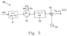
図2に、受信信号r(t)から標本化された信号
![]()
![]()
![]()
![]()
離散周波数領域での実装
式(5)で説明したように、チャネルの最大遅延−ドップラ・スプレッド(τmax,νmax)は、パイロット密度により裏付けされることのできる値を超えてはならない。式(10)における積分がパイロット密度により裏付けされる最大値を超えて実行される場合、積分は、値域(0≦k<K=Nfft/M,0≦l<Q)にわたって標本化されたものの離散和により近似でき、そして
As explained in the implementation equation (5) in the discrete frequency domain, the maximum delay-Doppler spread (τ max , ν max ) of the channel should not exceed a value that can be supported by the pilot density. If the integration in equation (10) is performed beyond the maximum value supported by the pilot density, the integration was sampled over the range (0 ≦ k <K = N ftt / M, 0 ≦ l <Q). Can be approximated by a discrete sum of things, and
(τmax,νmax)を超える値域にわたる積分は、好ましくない雑音が取り込まれるので検出性能を劣化させる可能性がある。しかしながら、検出の複雑さは、以下で説明するように著しく低減できる。検出器は、それで動作要件および装置性能に従って、性能と複雑さとの間でトレードオフをとることができる。 Integration over a range exceeding (τ max , ν max ) may degrade detection performance because undesirable noise is captured. However, the detection complexity can be significantly reduced as described below. The detector can then trade off between performance and complexity according to operating requirements and device performance.
サイクリック・プレフィックス・ウィンドウ内に適切に配置される場合、式(14)の最後の部分の畳み込みは循環となり、そしてこのようにDFT(離散フーリエ変換)を用いて周波数領域で評価できる。 When properly positioned within the cyclic prefix window, the convolution of the last part of equation (14) is circular and can thus be evaluated in the frequency domain using DFT (Discrete Fourier Transform).
C[n,m]は、また、パイロット信号が第nOFDMシンボル内の第mサブキャリアで伝送される場合のみ非ゼロであることに留意されたい。また、|C[n,m]|が全ての(非ゼロ)パイロット信号に対して一定であり、そしてC[n,m]が時間−周波数プレーン内でスロープが一定の線を形成すると、この実施形態は、本明細書の背景技術で言及した特許文献1に与えられている先行技術に帰着することに留意されたい。 Note that C [n, m] is also non-zero only if the pilot signal is transmitted on the mth subcarrier in the nth OFDM symbol. Also, if | C [n, m] | is constant for all (non-zero) pilot signals and C [n, m] forms a constant slope line in the time-frequency plane, It should be noted that the embodiments result in the prior art given in US Pat.
さらに、
![]()
![]()
![]()
![]()
![]()
![]()
一定の間隔で配置されたパイロット・パターンまたは既に説明したそれらのホッピング変異に対して、所与の初期の時間−周波数オフセット仮定に対する対数尤度関数は、離散周波数領域で、 For a regularly spaced pilot pattern or those hopping variations already described, the log-likelihood function for a given initial time-frequency offset assumption is in the discrete frequency domain:
離散時間領域での実装
ある場合には、時間領域内で対数尤度基準を直接計算することがより有効になりうる。図1に関連して説明したパイロット・パターンに対して、パターンの時間−周波数写像C[n,m]は、サブキャリア・インデックスφn,φn+M,φn+2M,・・・,でのみ非ゼロであり、ここで、φnはシンボル・インデックスnの関数としてのホッピング系列であり、そしてMは当該シンボル内におけるパイロット挿入周期である(必ずしも元の一定間隔で配置されたパターンのパイロット挿入周期ではない)。このとき、式(21)は、
If there is an implementation in the discrete time domain, it may be more effective to directly calculate the log likelihood criterion in the time domain. For the pilot pattern described in connection with FIG. 1, the time-frequency mapping C [n, m] of the pattern is only at subcarrier indices φ n , φ n + M, φ n + 2M,. Is non-zero, where φ n is a hopping sequence as a function of symbol index n, and M is the pilot insertion period within the symbol (not necessarily the pilot insertion of the original regularly spaced pattern) Not a cycle). At this time, the equation (21) becomes
式(18)でm=φn+mMとした
![]()
![]()
循環シフト・パターンの特別な場合
複数のホッピング・パターンの検出は、それらがある共通の構造を有する場合、非常に簡単になる可能性がある。たとえば、異なるデバイスに循環シフト・パターンを割り当てることによる。検出は、この場合、基本パターンの時間−周波数写像に適合する二次元循環相関器を使用することにより達成できる。図3は、コスタス配列の循環シフト・パターンを示す。第2のパターンは、η個のOFDMシンボルおよび(μM+φ)個のサブキャリア分だけ元のパターンを循環シフトしたものである。一定間隔で配置された場合におけるように、異なるサブキャリア・オフセットφを有するパターンは、完全に直交である。コスタス配列のある種類では、φが同じでmが異なる2つのパターンは、周期あたり高々1つの一致を見るだけであり、図6の例を参照されたい。長さLのコスタス系列に対して、セルが時間同期を取られていると、異なるセルを識別するために、全体でL×M×N個の異なる循環シフトがあることに留意されたい。一方、非同期のネットワークに対しては、L×Mの明確な循環周波数シフトがある。
The special case of cyclic shift patterns The detection of multiple hopping patterns can be very simple if they have some common structure. For example, by assigning a cyclic shift pattern to different devices. Detection can be achieved in this case by using a two-dimensional cyclic correlator that fits the time-frequency mapping of the basic pattern. FIG. 3 shows the cyclic shift pattern of the Costas sequence. The second pattern is a cyclic shift of the original pattern by η OFDM symbols and (μM + φ) subcarriers. As in the case of regular intervals, patterns with different subcarrier offsets φ are completely orthogonal. For some types of Costas arrays, two patterns with the same φ but different m only see at most one match per period, see the example in FIG. Note that for a length L Costas sequence, if the cells are time synchronized, there will be a total of L × M × N different cyclic shifts to identify the different cells. On the other hand, for asynchronous networks, there are L × M distinct cyclic frequency shifts.
人為的に導入される循環シフトに加えて、パイロット・パターンはまた、様々な理由のために、異なる基地局からのパターンまたは特別な端末のサンプリング点のような他の参照に関して、局所規模の時間−周波数オフセットを、また有する場合がある。この初期オフセットは、本質的に、オフセットが値域0≦τ0<Tsおよび0≦ν0<fs内にあるという制約を除いて、上記と同じであり、そして(τ0,ν0)で表示される。この値域外の任意のオフセットは、インデックスη、μおよびφの中に畳み込まれるであろう。循環シフト・パイロット・パターンの検出は、この場合、図3において拡大したスケールで示されているように、仮定された時間−周波数座標
In addition to artificially introduced cyclic shifts, pilot patterns can also be used for various reasons with respect to other references, such as patterns from different base stations or special terminal sampling points, on a local scale. -It may also have a frequency offset. This initial offset is essentially the same as above, except that the offset is in the
二次元相関器がどのように実装できるかを明示するために、図3で示されているものから、周波数領域のパイロット挿入周期Mを1にすることにより簡略化した例を考える。初期の時間−周波数オフセット(τ0,ν0)の各仮定に対して、L×N(6×7)の入力配列は、図4内の第1のマトリックス51で示されているように、シンボル期間にわたるN個の長さLのDFTを形成し、そして周波数領域の標本をN個の連続する列内に配置することにより形成される。初期の時間−周波数オフセット仮定は、計算の重複を回避するために、シンボル期間およびサブキャリア帯域の一部として好適に選択されるべきである。
To clearly show how the two-dimensional correlator can be implemented, consider a simplified example by setting the frequency domain pilot insertion period M to 1 from what is shown in FIG. For each assumption of initial time-frequency offset (τ 0 , ν 0 ), the L × N (6 × 7) input array is as shown in the
一旦入力配列が設定されると、パターン検索が始まる。まず、コスタス配列がシンボル・インデックスの周波数ホッピング系列{0,2,1,4,5,3,×}として表現され、ここで”×”はパイロットのサブキャリアを有しないシンボルを示す。この系列は、視覚的に説明するために入力配列の下に記載されている。第1の工程で、配列の列が、図4内の第2のマトリックス52で説明されているように、このホッピング系列に対応する分だけ行(サブキャリア)インデックス内で循環的に回転され、そして”×”印が付されているものを除いて列(シンボル)インデックスを横断して和がとられ、大きさL=6の列ベクトルをもたらす。このベクトルは、それから図5における出力配列50の第1列55に配置される。第2の工程で、図4内の第3のマトリックス53で説明されているように、コスタス系列が1単位だけ右側に循環的にシフトされ、そして入力配列51の列が循環的に回転され、そして第1の工程におけるように和がとられる。得られるベクトルは、それから図5内の出力配列の第2列56に配置される。この処理は、全てのN個の可能なコスタス系列の循環シフトが尽きるまで続けられる。L×Nの出力配列50は、それで所与の(τ0,ν0)に対してコスタス配列の循環シフトに関するL×N個の可能な全ての仮定の一般化対数尤度を含むであろう。尤度の検定および閾値化は、それから、どのような対象が存在するかどうかを決定するために行うことができる。図5に示されている出力配列50は、2つの突出したピークを明確に示しており、1つは(η=0,μ=0)にあり、出力配列50の第1列55内の58で表示され、そして他は(η=2,μ=2)にあり、出力配列50の第3列57内の59で表示されている。列57に配置されているベクトルは、上で説明したように図4の第4マトリックス54から導出される。
Once the input sequence is set, the pattern search begins. First, the Costas array is expressed as a frequency hopping sequence {0, 2, 1, 4, 5, 3, x} of symbol index, where “x” indicates a symbol having no pilot subcarrier. This series is listed below the input sequence for visual explanation. In the first step, the columns of the array are rotated cyclically in the row (subcarrier) index by the amount corresponding to this hopping sequence, as described in the
図4および図5で説明した相関処理は、前もって記録されたデータを含むメモリ・バッファ上で生じる。その代わりに、古いデータが掃き出されながら、新しいデータが着信し、そして配列を満たし続けるスライディング・ウィンドウ内に、実時間で同じ処理が実行できる。いずれの場合も、メモリ・バッファのローディングおよびベクトルの循環回転は、物理的にバッファ内容を移動させることなく、アドレス・ポインタを変更することにより、全て遂行できる。最後に、例ではコスタス配列の単一周期を示しているけれども、複数周期への拡張は容易である。計算効率のよい実装は、相関を行う前に入力配列を形成するために複数周期内でエネルギーの和をとることである。 The correlation process described in FIGS. 4 and 5 occurs on a memory buffer that contains previously recorded data. Instead, the same processing can be performed in real time in a sliding window where new data arrives and continues to fill the array as old data is swept out. In either case, memory buffer loading and vector rotation can all be accomplished by changing the address pointer without physically moving the buffer contents. Finally, although the example shows a single period of the Costas array, expansion to multiple periods is easy. A computationally efficient implementation is to sum the energy within multiple periods to form the input array before performing the correlation.
この特別な場合のスライディング・ウィンドウによる実施形態のための手順を、以下で簡潔に説明する。上で説明したオフラインでの実施形態は、データが既にバッファ内に読み込まれ、そしてしたがってデータの取得工程が割愛できることを除いて、同じである。
1.1つのシンボル期間にわたって受信した標本に関する適当な長さの(ゼロ詰め)DFTを実行する。DFTの長さは、初期の周波数オフセットν0に関する仮定に依存する。
2.DFT出力の絶対値の自乗を入力配列の第1列に配置する。
3.入力配列内の列の各々を行(サブキャリア)インデックス内でコスタス系列に対応する分だけ(物理的な内容またはポインタのいずれかで)循環的に回転する。
4.入力配列を列(シンボル)インデックスを横断して和をとり、そして得られる列ベクトルを出力並列の第1列に配置する。
5.工程3の結果として移動された入力配列のポインタをリセットし、そして入力/出力配列を(循環的に列を右側に回転しながら)1ポジションだけ進める。
6.1シンボル期間にわたって受信された標本の次のセグメントを取得する。このセグメントは、τ0に関する仮定に依存して前のものと重なる可能性がある。
7.工程1に戻る。
The procedure for this special case sliding window embodiment is briefly described below. The offline embodiment described above is the same except that the data has already been read into the buffer and thus the data acquisition process can be omitted.
1. Perform an appropriate length (zero-padded) DFT on the samples received over one symbol period. The length of the DFT depends on assumptions about the initial frequency offset ν 0 .
2. The square of the absolute value of the DFT output is placed in the first column of the input array.
3. Each column in the input array is rotated in a row (subcarrier) index by the amount corresponding to the Costas sequence (either physical content or pointer).
4). The input array is summed across the column (symbol) index and the resulting column vector is placed in the first column in output parallel.
5. Reset the pointer of the input array moved as a result of
6. Acquire the next segment of samples received over one symbol period. This segment can overlap with the previous depending on the assumptions about τ 0 .
7). Return to step 1.
シミュレーション結果
検出器の性能を評価するために、図6で説明しているコスタス配列パイロット・パターン60を考える。パイロット・パターン60は、一定の間隔を空けたパイロット・パターンの水平方向の走査線を循環的にシフトすることにより生成される。第1のアクセス・ポイントは、オフセットなしの基本信号を有するパイロット・パターン61であり、そして第2のアクセス・ポイントは、図6に(m,n)=(2,1)に対して示しているように、基本信号を周波数でnfp、そして時間でmTだけ循環的にシフトした、パイロット・パターン62を有する。N=6 GF(7)の完全に周期的なコスタス系列が両方のコスタス・パイロット・パターン61,62に対して使用されているので、2つのパターン間で各周期63における一致数は、この例では1つである。
In order to evaluate the performance of the simulation result detector, consider the Costas
表1に、シミュレーションを行った2つの特定の配列に関するパラメータを示す。公平に比較するために、両方は、約1/256のパイロット密度を有する。長さ16の配列に対するOFDMシンボルのFFTの大きさは、1024である。この場合ではM=16であるので、裏付けのできる最大遅延スプレッドは、1024/16=64チップであり、サイクリック・プレフィックスの長さに設定される。長さ30に対するOFDMシンボルのFFTの大きさは、512であり、すなわち、OFDMシンボルの間隔は、第1の配列におけるそれの半分である。しかしながら、サイクリック・プレフィックスの長さは、同じ最大遅延スプレッドを収容できるように、同じままである。
Table 1 shows the parameters for the two specific sequences that were simulated. Both have a pilot density of approximately 1/256 for a fair comparison. The FFT size of the OFDM symbol for an array of length 16 is 1024. In this case, since M = 16, the maximum delay spread that can be supported is 1024/16 = 64 chips, which is set to the length of the cyclic prefix. The FFT size of the OFDM symbol for
シミュレーションにおいてチャネルを各々実現するために、区間[0,Ts)および[0,fs/2)内で一様に分布するランダムな初期の時間−周波数オフセット(τ0,ν0)を導入する。相関器は、入力配列を形成する場合、単一の仮定(τ0,ν0)=(0,0)を立てる。これは、パイロット・パターンを時間領域でTs秒、そして周波数領域でfsヘルツの間隔で大まかに探索することに対応する。真の目標が、検出された位置の両側にある1つのシンボルおよび1つのサブキャリア内にあると、検出が上首尾であるといえる。セル識別および大まかな同期が得られてから、チャネルの遅延−ドップラ応答の境界を確立するために、さらなる精細な探索を続けることができる。これは、SNR(信号対雑音比)が良好な場合はある簡単な補間を、またはその他の場合はコヒーレントなDFTを含むことができる。 In order to realize each channel in the simulation, a random initial time-frequency offset (τ 0 , ν 0 ) uniformly distributed in the interval [0, T s ) and [0, f s / 2) is introduced. To do. When the correlator forms the input array, it makes a single assumption (τ 0 , ν 0 ) = (0,0). This corresponds to roughly searching the pilot pattern at intervals of T s seconds in the time domain and f s hertz in the frequency domain. If the true target is within one symbol and one subcarrier on either side of the detected location, the detection can be said to be successful. Once cell identification and coarse synchronization are obtained, further refinement can be continued to establish the channel delay-Doppler response boundary. This may include some simple interpolation if the signal-to-noise ratio (SNR) is good, or else a coherent DFT.
表2は、全てのシミュレーションに共通な少しの他のパラメータを記載している。2つの電力遅延ドップラ・プロファイルがシミュレーションされる。”フラット”チャネルは、平均がゼロのガウス変数を単にランダムに実現したものであり、そして”フル”チャネルは、最大遅延−ドップラ領域全体に広がる”ケース3×ベッセル(Case3×Bessel)”プロファイルを有する。それらは、チャネルのダイバーシティ次数について2つの極端を表わしている。実際には現実的な性能は、双方の間のどこかに位置するはずである。特に明記しない限り、時間にわたって観測される周期の数は、1である。
Table 2 lists a few other parameters that are common to all simulations. Two power delay Doppler profiles are simulated. The “flat” channel is simply a randomized implementation of a Gaussian variable with an average of zero, and the “full” channel has a “
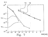
図7は、単一セルの誤検出確率に関するシミュレーションの図である。星印のある実線71は配列1(コスタス16)、”フル”チャネルであり、そして丸印のある実線72は配列2(コスタス30)、”フル”チャネルである。星印のある破線73は配列1(コスタス16)、”フラット”チャネルであり、そして丸印のある破線74は配列2(コスタス30)、”フラット”チャネルである。チャネル内のダイバーシティ次数により大きく影響されるけれども、性能は2つの極端な場合で非常にロバストである。第2配列(コスタス30)に関するより大きなピーク対サイドローブ比は、”フル”チャネルにおいてより高いSNR値域まで大した利得をもたらさない。これは、主に、第2配列はより多くの仮定(7440)を有し、そしてしたがって誤りを犯す機会がより多くあるという事実のためである。
FIG. 7 is a diagram of simulation regarding the false detection probability of a single cell. A
第2の一連のシミュレーションは、同じサブキャリア・オフセットφ=0を有する2つのセルを含む。第1のセルは、平均SNRが0dBで(η,μ)=(0,0)に位置しており、一方第2のセルは、第1のセルに対して信号電力が可変で(η,μ)=(6,7)に位置している。これまでに触れた受信機でのオフセットに加えて、2つのセルは、同様に分布しているランダムな相対的時間−周波数オフセットを有している。2つのセルのシミュレーションでは、両方のセルが首尾よく検出される場合のみ、検出が上首尾であるといえる。これは、相関出力配列における2つの基準が最大となる位置が2つの目標の位置に対応する場合に、起こる。参考のため、2つの強さの等しいセルに対する典型的な配列を図8に示す。 The second series of simulations includes two cells with the same subcarrier offset φ = 0. The first cell is located at (η, μ) = (0, 0) with an average SNR of 0 dB, while the second cell has a variable signal power relative to the first cell (η, μ) = (6, 7). In addition to the receiver offsets mentioned so far, the two cells have a random relative time-frequency offset that is also distributed. In the simulation of two cells, the detection can be said to be successful only if both cells are successfully detected. This occurs when the position where the two criteria in the correlation output array are maximum corresponds to the two target positions. For reference, a typical arrangement for two equal strength cells is shown in FIG.
図9は、SNRが0dBでの”フル”チャネルにおける2つのセルの誤検出確率に関するシミュレーションの図であり、そして図10は、SNRが0dBでの”フラット”チャネルにおける2つのセルの誤検出確率に関するシミュレーションの図である。図9及び図10における実線は1周期分の観測を表わし、そして図9および図10における破線は2周期分の観測を表わす。図9及び図10で星印のある線は配列1(コスタス16)を表わし、そして図9および図10で丸印のある線は配列2(コスタス30)を表わす。 FIG. 9 is a simulation of the false detection probability of two cells in a “full” channel with an SNR of 0 dB, and FIG. 10 shows the false detection probability of two cells in a “flat” channel with an SNR of 0 dB. FIG. The solid line in FIGS. 9 and 10 represents the observation for one period, and the broken line in FIGS. 9 and 10 represents the observation for two periods. 9 and 10, the line with an asterisk represents array 1 (Costas 16), and the line with a circle in FIGS. 9 and 10 represents array 2 (Costas 30).
図9および図10におけるP1およびP2は、それぞれのパイロット信号からの受信電力である。 P 1 and P 2 in FIGS. 9 and 10 are received power from the respective pilot signals.
”フル”チャネルにおける性能は、図9で、2つのセルの強い方が、弱い方が見逃されるにも係わらず、ほとんど常に検出されるという隠れた事実を考慮すると、1周期(Q=1)の観測のみで、かなり良好である。ある時間選択性を有するチャネルでは、性能は、累積するパイロット周期の数を増やすことにより、Q=2の場合誤り率10パーセントで利得が3dBであることからも明らかなように、望ましいレベルまで改善される可能性がある。一方、”フラット”チャネルの場合に対しては、Q=2に対して観測される利得は、曲線のスロープが変わらないままであるので、主に、ダイバーシティよりはむしろノイズ抑圧による。 The performance in the “full” channel is one period (Q = 1) in FIG. 9, taking into account the hidden fact that the stronger of the two cells is almost always detected even though the weaker one is missed. It is quite good only by observations. For channels with some time selectivity, the performance improves to the desired level by increasing the number of accumulated pilot periods, as evidenced by an error rate of 10 percent and a gain of 3 dB for Q = 2. There is a possibility that. On the other hand, for the “flat” channel case, the gain observed for Q = 2 is mainly due to noise suppression rather than diversity because the slope of the curve remains unchanged.
より多くのパイロット周期を観測することに加えて、検出性能は、少しの他の測度により、またはある条件のもとでさらに改善できる。たとえば、初期の時間−周波数オフセット(τ0,ν0)の仮定の数を増やすことができる。これは、検索密度を効率的に増やし、そしてしたがって計算が複雑になるのを犠牲にして、対数尤度関数のピークを見つける機会を増やす。ネットワーク設計者はまた、識別インデックス(η,μ,φ)に制約を課して、偽陽性率を低減できる。最後に、セルおよび端末の中で初期の時間−周波数オフセットは、多分、シミュレーションで想定されているものより多い。特にセル間でのシンボル・アライメントは、OFDMシステムにおける基本的な仮定であり、とても著しく干渉を軽減するはずである。 In addition to observing more pilot periods, the detection performance can be further improved by a few other measures or under certain conditions. For example, the assumed number of initial time-frequency offsets (τ 0 , ν 0 ) can be increased. This effectively increases the search density and thus increases the chances of finding the peak of the log-likelihood function at the expense of computational complexity. Network designers can also impose constraints on the identification index (η, μ, φ) to reduce the false positive rate. Finally, the initial time-frequency offset in the cell and terminal is probably more than what is assumed in the simulation. In particular, symbol alignment between cells is a basic assumption in OFDM systems and should significantly reduce interference.
パイロット・パターンを検出するための、説明した方法を実行する検出器は、通信システムのノード、たとえば基地局、携帯電話、または任意の他の種類の無線通信デバイス内に実装されるのが自然であろう。本方法は、記憶部に格納されたソフトウェア・コードとして好適に実装され、そして処理デバイスにより実行される。 A detector that performs the described method for detecting a pilot pattern is naturally implemented in a node of a communication system, such as a base station, a mobile phone, or any other type of wireless communication device. I will. The method is preferably implemented as software code stored in a storage unit and executed by a processing device.
根本的な設計原理は、OFDMシステムに固有の直交する時間−周波数分割フォーマットに適合するようになっており、それにより、DFTを好適に使用して時間と周波数(または遅延とドップラ)間の転換を、大抵は含む受信機のアルゴリズムに繋がる。データ・シンボルの復調はまた、DFTによって達成されるので、専用かつ融通性のあるハードウェアのDFTアクセラレータは、モデムからのデータ・ビットを受信する際に、殆んど全ての計算を処理できる。 The underlying design principle is adapted to the orthogonal time-frequency division format inherent in OFDM systems, so that DFT is preferably used to convert between time and frequency (or delay and Doppler). Usually leads to receiver algorithms. Demodulation of data symbols is also accomplished by DFT, so a dedicated and flexible hardware DFT accelerator can handle almost all computations when receiving data bits from a modem.
Claims (14)
未知の初期時間−周波数オフセット(τ0,ν0)を仮定するステップと、
前記パイロット信号sp(t)と前記仮定された初期時間−周波数オフセット(τ0,ν0)とにより特定される仮定の空間に対する対数尤度関数の値Λ(τ0,ν0)を計算するステップと、
前記パイロット・パターンを検出し時間−周波数オフセット(τ0,ν0)を推定するために、前記計算された値を基準値に関連付けるステップと、
を含み、
パイロット・パターンを検出する前記方法は、前記OFDMシステム内の複数の機器に対する、同期と識別との少なくとも一方に用いられ、
前記OFDMシステム内の各々の機器は、該各々の機器に割り当てられた異なる循環シフトを有する同一の時間−周波数ホッピング・パターンを使用する
ことを特徴とする方法。In orthogonal frequency division multiplexing (OFDM) receiver in the system signal r (t), the cyclic shift time - a method of detecting the pilot pattern comprises a frequency hopping pattern having a Rupa pilots signals s p (t) There,
Assuming an unknown initial time-frequency offset (τ 0 , ν 0 );
The pilot signal s p (t) and the assumed initial time - frequency offset (τ 0, ν 0) value of the log-likelihood function for hypothetical space specified by the Λ (τ 0, ν 0) calculated And steps to
Associating the calculated value with a reference value to detect the pilot pattern and estimate a time-frequency offset (τ 0 , ν 0 );
Only including,
The method of detecting a pilot pattern is used for at least one of synchronization and identification for a plurality of devices in the OFDM system;
Each method in the OFDM system uses the same time-frequency hopping pattern with different cyclic shifts assigned to each device .
前記計算された値を関連付ける前記ステップは、前記計算された値を前記閾値と比較するステップを有する
ことを特徴とする請求項1に記載の方法。The reference value is a threshold value,
The method of claim 1, wherein associating the calculated value comprises comparing the calculated value to the threshold.
該評価は、
遅延ドップラ相関を実行するステップと、
前記仮定の空間にわたってエネルギーを積分するステップと、
を有することを特徴とする請求項1乃至3の何れか一項に記載の方法。The step of calculating a value is a direct evaluation of the log-likelihood function Λ (τ 0 , ν 0 );
The evaluation is
Performing delayed Doppler correlation; and
Integrating energy over the hypothesized space;
The method according to any one of claims 1 to 3, characterized by comprising:
前記対数尤度関数を計算するため標本
チップ継続時間Tcの倍数となるように遅延仮定τ0を選択するステップと、
を有することを特徴とする請求項5に記載の方法。further,
Sample for calculating the log-likelihood function
Selecting the delay assumption τ 0 to be a multiple of the chip duration T c ;
6. The method of claim 5, comprising:
時間−周波数マップ
ことを特徴とする請求項8に記載の方法。The log-likelihood function is the sum of the received signal energy over the assumed pilot signal position on the discrete time-frequency plane.
Time-frequency map
記憶部と、
処理装置と、
を含み、請求項1乃至11の何れか一項に記載の方法を実行するよう構成されていることを特徴とする検出器。A detector implemented in the OFDM system for receiving at least one pilot signal generated in the OFDM system;
A storage unit;
A processing device;
A detector, characterized in that it is arranged to carry out the method according to any one of claims 1 to 11 .
前記OFDMシステム内の第1ノードはパイロット信号を送信するのに適しており、
前記OFDMシステム内の第2ノードは前記パイロット信号を受信するのに適しており、
前記第2ノードは、さらに、請求項1乃至11の何れか一項に記載の方法を実行するのに適した検出器を含む
ことを特徴とするシステム。An OFDM system comprising at least one base station and at least one mobile communication device,
A first node in the OFDM system is suitable for transmitting a pilot signal;
A second node in the OFDM system is suitable for receiving the pilot signal;
The system second node is further characterized in that it comprises a detector suitable for performing the method according to any one of claims 1 to 11.
Applications Claiming Priority (1)
| Application Number | Priority Date | Filing Date | Title |
|---|---|---|---|
| PCT/US2006/035128 WO2008033117A1 (en) | 2006-09-11 | 2006-09-11 | Detection of time-frequency hopping patterns |
Publications (2)
| Publication Number | Publication Date |
|---|---|
| JP2010503313A JP2010503313A (en) | 2010-01-28 |
| JP5074501B2 true JP5074501B2 (en) | 2012-11-14 |
Family
ID=37946357
Family Applications (1)
| Application Number | Title | Priority Date | Filing Date |
|---|---|---|---|
| JP2009527334A Expired - Fee Related JP5074501B2 (en) | 2006-09-11 | 2006-09-11 | Time-frequency hopping pattern detection |
Country Status (5)
| Country | Link |
|---|---|
| US (1) | US8295311B2 (en) |
| EP (1) | EP2067327B1 (en) |
| JP (1) | JP5074501B2 (en) |
| CN (1) | CN101512998B (en) |
| WO (1) | WO2008033117A1 (en) |
Families Citing this family (101)
| Publication number | Priority date | Publication date | Assignee | Title |
|---|---|---|---|---|
| US8300674B2 (en) * | 2007-01-12 | 2012-10-30 | Telefonaktiebolaget L M Ericsson (Publ) | Method and apparatus for complexity reduction in detection of delay and Doppler shifted signature sequences |
| WO2008124688A1 (en) * | 2007-04-06 | 2008-10-16 | Olympus Communication Technology Of America, Inc. | Methods and systems for diversity combining of synchronization statistics in ofdm systems |
| US8811331B2 (en) * | 2008-04-10 | 2014-08-19 | Telefonaktiebolaget L M Ericsson (Publ) | Pilot design using costas arrays |
| CN101321150B (en) * | 2008-07-16 | 2010-09-01 | 清华大学 | Combined synchronization process and its receiving terminal based on two-dimension short time slippage self-correlation |
| US7940740B2 (en) | 2009-02-03 | 2011-05-10 | Motorola Mobility, Inc. | Apparatus and method for communicating and processing a positioning reference signal based on identifier associated with a base station |
| US8730925B2 (en) | 2009-04-09 | 2014-05-20 | Motorola Mobility Llc | Method and apparatus for generating reference signals for accurate time-difference of arrival estimation |
| KR101644881B1 (en) | 2009-04-10 | 2016-08-03 | 엘지전자 주식회사 | Apparatus and metheod for positioing a user equipment |
| CN101883379B (en) * | 2009-05-05 | 2012-12-26 | 上海摩波彼克半导体有限公司 | Method for realizing two-phase measuring optimization of wireless terminal adjacent subdistricts in wireless communication system |
| US8929750B2 (en) | 2009-05-18 | 2015-01-06 | Nippon Telegraph And Telephone Corporation | Signal generating circuit, optical signal transmitting apparatus, signal receiving circuit, method for establishing optical signal synchronization, and optical signal synchronization system |
| US9002354B2 (en) | 2009-06-12 | 2015-04-07 | Google Technology Holdings, LLC | Interference control, SINR optimization and signaling enhancements to improve the performance of OTDOA measurements |
| US8483707B2 (en) | 2009-06-26 | 2013-07-09 | Motorola Mobility Llc | Wireless terminal and method for managing the receipt of position reference singals for use in determining a location |
| US8374633B2 (en) | 2009-10-05 | 2013-02-12 | Motorola Mobility Llc | Muting indication to enable improved time difference of arrival measurements |
| JP5511434B2 (en) * | 2010-02-23 | 2014-06-04 | 三菱電機株式会社 | Frame synchronizer and receiver |
| US8509102B2 (en) | 2010-02-24 | 2013-08-13 | Motorola Mobility Llc | Threshold determination in TDOA-based positioning system |
| US9203489B2 (en) | 2010-05-05 | 2015-12-01 | Google Technology Holdings LLC | Method and precoder information feedback in multi-antenna wireless communication systems |
| US8582698B2 (en) * | 2010-05-10 | 2013-11-12 | Telefonaktiebolaget Lm Ericsson (Publ) | Reduced complexity timing estimation for locating the position of a mobile terminal |
| US9444514B2 (en) | 2010-05-28 | 2016-09-13 | Cohere Technologies, Inc. | OTFS methods of data channel characterization and uses thereof |
| US8976851B2 (en) | 2011-05-26 | 2015-03-10 | Cohere Technologies, Inc. | Modulation and equalization in an orthonormal time-frequency shifting communications system |
| US9130638B2 (en) | 2011-05-26 | 2015-09-08 | Cohere Technologies, Inc. | Modulation and equalization in an orthonormal time-frequency shifting communications system |
| US9071286B2 (en) | 2011-05-26 | 2015-06-30 | Cohere Technologies, Inc. | Modulation and equalization in an orthonormal time-frequency shifting communications system |
| US9071285B2 (en) | 2011-05-26 | 2015-06-30 | Cohere Technologies, Inc. | Modulation and equalization in an orthonormal time-frequency shifting communications system |
| US10667148B1 (en) | 2010-05-28 | 2020-05-26 | Cohere Technologies, Inc. | Methods of operating and implementing wireless communications systems |
| US10681568B1 (en) | 2010-05-28 | 2020-06-09 | Cohere Technologies, Inc. | Methods of data channel characterization and uses thereof |
| US11943089B2 (en) | 2010-05-28 | 2024-03-26 | Cohere Technologies, Inc. | Modulation and equalization in an orthonormal time-shifting communications system |
| US8428022B2 (en) | 2010-08-27 | 2013-04-23 | Motorola Mobility Llc | Method and apparatus for transmitting positioning reference signals in a wireless communication network |
| US9590779B2 (en) | 2011-05-26 | 2017-03-07 | Cohere Technologies, Inc. | Modulation and equalization in an orthonormal time-frequency shifting communications system |
| US9294315B2 (en) | 2011-05-26 | 2016-03-22 | Cohere Technologies, Inc. | Modulation and equalization in an orthonormal time-frequency shifting communications system |
| US9031141B2 (en) | 2011-05-26 | 2015-05-12 | Cohere Technologies, Inc. | Modulation and equalization in an orthonormal time-frequency shifting communications system |
| CN102546116B (en) * | 2012-02-14 | 2015-07-29 | 西安电子科技大学 | Based on the Frequency Hopping Signal blind checking method of compressed sensing |
| US10411843B2 (en) | 2012-06-25 | 2019-09-10 | Cohere Technologies, Inc. | Orthogonal time frequency space communication system compatible with OFDM |
| US9912507B2 (en) | 2012-06-25 | 2018-03-06 | Cohere Technologies, Inc. | Orthogonal time frequency space communication system compatible with OFDM |
| US10090972B2 (en) | 2012-06-25 | 2018-10-02 | Cohere Technologies, Inc. | System and method for two-dimensional equalization in an orthogonal time frequency space communication system |
| CN104662855B (en) * | 2012-06-25 | 2018-10-23 | 科希尔技术股份有限公司 | Modulation in orthogonal mobile communication system and equilibrium |
| US9967758B2 (en) | 2012-06-25 | 2018-05-08 | Cohere Technologies, Inc. | Multiple access in an orthogonal time frequency space communication system |
| US10003487B2 (en) | 2013-03-15 | 2018-06-19 | Cohere Technologies, Inc. | Symplectic orthogonal time frequency space modulation system |
| US10469215B2 (en) | 2012-06-25 | 2019-11-05 | Cohere Technologies, Inc. | Orthogonal time frequency space modulation system for the Internet of Things |
| US9929783B2 (en) | 2012-06-25 | 2018-03-27 | Cohere Technologies, Inc. | Orthogonal time frequency space modulation system |
| US20140105315A1 (en) * | 2012-10-12 | 2014-04-17 | The Governors Of The University Of Alberta | Frequency time block modulation for mitigating doubly-selective fading |
| US9813262B2 (en) | 2012-12-03 | 2017-11-07 | Google Technology Holdings LLC | Method and apparatus for selectively transmitting data using spatial diversity |
| US9591508B2 (en) | 2012-12-20 | 2017-03-07 | Google Technology Holdings LLC | Methods and apparatus for transmitting data between different peer-to-peer communication groups |
| US9979531B2 (en) | 2013-01-03 | 2018-05-22 | Google Technology Holdings LLC | Method and apparatus for tuning a communication device for multi band operation |
| US10229697B2 (en) | 2013-03-12 | 2019-03-12 | Google Technology Holdings LLC | Apparatus and method for beamforming to obtain voice and noise signals |
| US9386542B2 (en) | 2013-09-19 | 2016-07-05 | Google Technology Holdings, LLC | Method and apparatus for estimating transmit power of a wireless device |
| US9621389B2 (en) * | 2013-09-30 | 2017-04-11 | Volvo Car Corporation | Method to introduce complementing training symbols into a 802.11p OFDM frame in vehicular communications |
| US9549290B2 (en) | 2013-12-19 | 2017-01-17 | Google Technology Holdings LLC | Method and apparatus for determining direction information for a wireless device |
| US9491007B2 (en) | 2014-04-28 | 2016-11-08 | Google Technology Holdings LLC | Apparatus and method for antenna matching |
| US9478847B2 (en) | 2014-06-02 | 2016-10-25 | Google Technology Holdings LLC | Antenna system and method of assembly for a wearable electronic device |
| US10158394B2 (en) | 2015-05-11 | 2018-12-18 | Cohere Technologies, Inc. | Systems and methods for symplectic orthogonal time frequency shifting modulation and transmission of data |
| US10090973B2 (en) | 2015-05-11 | 2018-10-02 | Cohere Technologies, Inc. | Multiple access in an orthogonal time frequency space communication system |
| EP3098623A1 (en) * | 2015-05-25 | 2016-11-30 | Autoliv Development AB | A vehicle radar system |
| US9866363B2 (en) | 2015-06-18 | 2018-01-09 | Cohere Technologies, Inc. | System and method for coordinated management of network access points |
| US10574317B2 (en) | 2015-06-18 | 2020-02-25 | Cohere Technologies, Inc. | System and method for providing wireless communication services using configurable broadband infrastructure shared among multiple network operators |
| CN114070701B (en) | 2015-06-27 | 2024-05-14 | 凝聚技术股份有限公司 | OFDM compatible orthogonal time-frequency space communication system |
| US10892547B2 (en) | 2015-07-07 | 2021-01-12 | Cohere Technologies, Inc. | Inconspicuous multi-directional antenna system configured for multiple polarization modes |
| US10693581B2 (en) | 2015-07-12 | 2020-06-23 | Cohere Technologies, Inc. | Orthogonal time frequency space modulation over a plurality of narrow band subcarriers |
| KR102697299B1 (en) | 2015-09-07 | 2024-08-23 | 코히어 테크널러지스, 아이엔씨. | Multiple access using orthogonal time-frequency spatial modulation |
| US11038733B2 (en) | 2015-11-18 | 2021-06-15 | Cohere Technologies, Inc. | Orthogonal time frequency space modulation techniques |
| CN108781072B (en) | 2015-12-09 | 2022-04-26 | 凝聚技术公司 | Pilot encapsulation using complex orthogonal functions |
| CN109348739B (en) | 2016-02-25 | 2022-10-28 | 凝聚技术公司 | Reference signal encapsulation for wireless communication |
| US10693692B2 (en) | 2016-03-23 | 2020-06-23 | Cohere Technologies, Inc. | Receiver-side processing of orthogonal time frequency space modulated signals |
| EP3437190B1 (en) | 2016-03-31 | 2023-09-06 | Cohere Technologies, Inc. | Channel acquisition using orthogonal time frequency space modulated pilot signal |
| US9667307B1 (en) | 2016-03-31 | 2017-05-30 | Cohere Technologies | Wireless telecommunications system for high-mobility applications |
| KR102250054B1 (en) | 2016-04-01 | 2021-05-07 | 코히어 테크널러지스, 아이엔씨. | TOMLINSON-HARASHIMA precoding in OTFS communication system |
| KR102276187B1 (en) | 2016-04-01 | 2021-07-12 | 코히어 테크놀로지스, 아이엔씨. | Iterative two-dimensional equalization of orthogonal time-frequency spatial modulated signals |
| WO2017201467A1 (en) | 2016-05-20 | 2017-11-23 | Cohere Technologies | Iterative channel estimation and equalization with superimposed reference signals |
| CN116865924A (en) | 2016-08-12 | 2023-10-10 | 凝聚技术公司 | Multiuser multiplexing of orthogonal time-frequency space signals |
| EP3497799A4 (en) | 2016-08-12 | 2020-04-15 | Cohere Technologies, Inc. | Iterative multi-level equalization and decoding |
| EP3497907A4 (en) | 2016-08-12 | 2020-03-04 | Cohere Technologies, Inc. | Localized equalization for channels with intercarrier interference |
| US11310000B2 (en) | 2016-09-29 | 2022-04-19 | Cohere Technologies, Inc. | Transport block segmentation for multi-level codes |
| WO2018064605A1 (en) | 2016-09-30 | 2018-04-05 | Cohere Technologies | Uplink user resource allocation for orthogonal time frequency space modulation |
| DE102016220882A1 (en) * | 2016-10-24 | 2018-04-26 | Fraunhofer-Gesellschaft zur Förderung der angewandten Forschung e.V. | Optimized hopping patterns for different sensor nodes and variable data lengths based on the telegram splitting transmission method |
| DE102016220883A1 (en) | 2016-10-24 | 2018-04-26 | Fraunhofer-Gesellschaft zur Förderung der angewandten Forschung e.V. | Optimized combination of preamble and data fields for sensor networks with low power consumption based on the telegram splitting method |
| WO2018106731A1 (en) | 2016-12-05 | 2018-06-14 | Cohere Technologies | Fixed wireless access using orthogonal time frequency space modulation |
| WO2018129554A1 (en) | 2017-01-09 | 2018-07-12 | Cohere Technologies | Pilot scrambling for channel estimation |
| WO2018140837A1 (en) | 2017-01-27 | 2018-08-02 | Cohere Technologies | Variable beamwidth multiband antenna |
| US10568143B2 (en) | 2017-03-28 | 2020-02-18 | Cohere Technologies, Inc. | Windowed sequence for random access method and apparatus |
| US11817987B2 (en) | 2017-04-11 | 2023-11-14 | Cohere Technologies, Inc. | Digital communication using dispersed orthogonal time frequency space modulated signals |
| EP4109983A1 (en) | 2017-04-21 | 2022-12-28 | Cohere Technologies, Inc. | Communication techniques using quasi-static properties of wireless channels |
| US11063804B2 (en) | 2017-04-24 | 2021-07-13 | Cohere Technologies, Inc. | Digital communication using lattice division multiplexing |
| EP3616265A4 (en) | 2017-04-24 | 2021-01-13 | Cohere Technologies, Inc. | Multibeam antenna designs and operation |
| CN111052692B (en) | 2017-07-12 | 2022-10-11 | 凝聚技术公司 | Data modulation method based on ZAK transformation |
| US11546068B2 (en) | 2017-08-11 | 2023-01-03 | Cohere Technologies, Inc. | Ray tracing technique for wireless channel measurements |
| US11324008B2 (en) | 2017-08-14 | 2022-05-03 | Cohere Technologies, Inc. | Transmission resource allocation by splitting physical resource blocks |
| CN111279337B (en) | 2017-09-06 | 2023-09-26 | 凝聚技术公司 | Wireless communication method implemented by wireless communication receiver device |
| WO2019051427A1 (en) | 2017-09-11 | 2019-03-14 | Cohere Technologies, Inc. | Wireless local area networks using orthogonal time frequency space modulation |
| EP3682607A4 (en) | 2017-09-15 | 2021-09-01 | Cohere Technologies, Inc. | Achieving synchronization in an orthogonal time frequency space signal receiver |
| WO2019060596A2 (en) | 2017-09-20 | 2019-03-28 | Cohere Technologies, Inc. | Low cost electromagnetic feed network |
| US11152957B2 (en) | 2017-09-29 | 2021-10-19 | Cohere Technologies, Inc. | Forward error correction using non-binary low density parity check codes |
| CN111919394B (en) | 2017-11-01 | 2022-05-27 | 凝聚技术公司 | Precoding in wireless systems using orthogonal time-frequency space-division multiplexing |
| US11184122B2 (en) | 2017-12-04 | 2021-11-23 | Cohere Technologies, Inc. | Implementation of orthogonal time frequency space modulation for wireless communications |
| WO2019138561A1 (en) * | 2018-01-12 | 2019-07-18 | 株式会社Nttドコモ | Radio base station and user equipment |
| WO2019157230A1 (en) | 2018-02-08 | 2019-08-15 | Cohere Technologies, Inc. | Aspects of channel estimation for orthogonal time frequency space modulation for wireless communications |
| US11489559B2 (en) | 2018-03-08 | 2022-11-01 | Cohere Technologies, Inc. | Scheduling multi-user MIMO transmissions in fixed wireless access systems |
| US11329848B2 (en) | 2018-06-13 | 2022-05-10 | Cohere Technologies, Inc. | Reciprocal calibration for channel estimation based on second-order statistics |
| US11522600B1 (en) | 2018-08-01 | 2022-12-06 | Cohere Technologies, Inc. | Airborne RF-head system |
| DE102018215191A1 (en) * | 2018-09-06 | 2020-03-12 | Fraunhofer-Gesellschaft zur Förderung der angewandten Forschung e.V. | Circular jump patterns |
| DE102018222859A1 (en) * | 2018-12-21 | 2020-06-25 | Fraunhofer-Gesellschaft zur Förderung der angewandten Forschung e.V. | Use of cyclically shifted basic patterns to optimize detection rates |
| US11350265B2 (en) | 2019-06-28 | 2022-05-31 | Apple Inc. | Presence discovery techniques |
| CN112039609B (en) * | 2020-08-28 | 2021-05-04 | 中国人民解放军国防科技大学 | Frequency conversion time testing device in frequency hopping communication equipment built-in test |
| CN112543162B (en) * | 2020-11-12 | 2022-02-22 | 重庆邮电大学 | Short wave communication time-frequency joint synchronization method based on Costas sequence |
| CN112769725B (en) * | 2020-12-23 | 2022-01-07 | 重庆邮电大学 | Costas sequence time-frequency joint synchronization method based on full-phase spectrum correction |
Family Cites Families (45)
| Publication number | Priority date | Publication date | Assignee | Title |
|---|---|---|---|---|
| US6047171A (en) | 1998-01-08 | 2000-04-04 | Ericsson Inc. | Method and apparatus for combating adjacent channel interference using multiple IF filters |
| US6088416A (en) | 1998-04-21 | 2000-07-11 | Trw Inc. | Method for reducing interference and increasing spectral efficiency |
| US6332006B1 (en) | 1998-11-18 | 2001-12-18 | Ericsson Inc. | Apparatus and methods for providing high-penetration messaging in wireless communications systems |
| US6320843B1 (en) | 1998-11-18 | 2001-11-20 | Ericsson Inc. | Wireless communications systems with standard and robust services and methods of operation thereof |
| US6654429B1 (en) | 1998-12-31 | 2003-11-25 | At&T Corp. | Pilot-aided channel estimation for OFDM in wireless systems |
| US6480556B1 (en) | 1999-04-27 | 2002-11-12 | Ericsson Inc. | Rate detection apparatus and method for variable rate speech encoding |
| US7027464B1 (en) * | 1999-07-30 | 2006-04-11 | Matsushita Electric Industrial Co., Ltd. | OFDM signal transmission scheme, and OFDM signal transmitter/receiver |
| US20070127553A1 (en) | 1999-08-13 | 2007-06-07 | Viasat, Inc. | Code Reuse Multiple Access For Satellite Return Link |
| US6233270B1 (en) | 1999-09-28 | 2001-05-15 | Telefonaktiebolaget Lm Ericsson (Publ) | Interference diversity in synchronized networks |
| US6556621B1 (en) | 2000-03-29 | 2003-04-29 | Time Domain Corporation | System for fast lock and acquisition of ultra-wideband signals |
| FI20000819A (en) | 2000-04-06 | 2002-01-25 | Nokia Mobile Phones Ltd | Method in receiver and receiver |
| US6961364B1 (en) | 2000-04-18 | 2005-11-01 | Flarion Technologies, Inc. | Base station identification in orthogonal frequency division multiplexing based spread spectrum multiple access systems |
| EP2262151B1 (en) | 2000-07-05 | 2017-10-04 | Sony Deutschland Gmbh | Pilot pattern design for multiple antennas in an OFDM system |
| US7418043B2 (en) | 2000-07-19 | 2008-08-26 | Lot 41 Acquisition Foundation, Llc | Software adaptable high performance multicarrier transmission protocol |
| US6594793B1 (en) | 2000-09-08 | 2003-07-15 | Ericsson Inc. | Methods and systems for multiplexing and decoding variable length messages in digital communications systems |
| US6842487B1 (en) | 2000-09-22 | 2005-01-11 | Telefonaktiebolaget Lm Ericsson (Publ) | Cyclic delay diversity for mitigating intersymbol interference in OFDM systems |
| US6754253B2 (en) | 2000-11-29 | 2004-06-22 | Ericsson Inc. | Receiver architecture for transmit diversity in CDMA system |
| US6990153B1 (en) | 2001-02-06 | 2006-01-24 | Agency For Science, Technology And Research | Method and apparatus for semi-blind communication channel estimation |
| JP4563622B2 (en) * | 2001-08-03 | 2010-10-13 | クラリオン株式会社 | Broadband AFC circuit and OFDM demodulator |
| JP2003069526A (en) * | 2001-08-22 | 2003-03-07 | Clarion Co Ltd | Ofdm demodulation device and its carrier frequency synchronous method |
| US7248559B2 (en) | 2001-10-17 | 2007-07-24 | Nortel Networks Limited | Scattered pilot pattern and channel estimation method for MIMO-OFDM systems |
| US7206359B2 (en) * | 2002-03-29 | 2007-04-17 | Scientific Research Corporation | System and method for orthogonally multiplexed signal transmission and reception |
| US6985498B2 (en) | 2002-08-26 | 2006-01-10 | Flarion Technologies, Inc. | Beacon signaling in a wireless system |
| US7313110B2 (en) | 2002-10-09 | 2007-12-25 | Telefonaktiebolaget L.M. Ericsson | Methods, systems, and computer program products for allocating bandwidth in a radio packet data system based on data rate estimates determined for one or more idle transmitter/sector scenarios |
| CN101610234B (en) * | 2003-01-07 | 2012-04-25 | 高通股份有限公司 | Pilot transmission schemes for wireless multi-carrier communication systems |
| CA2529270A1 (en) | 2003-06-18 | 2004-12-23 | Samsung Electronics Co., Ltd. | Apparatus and method for transmitting and receiving a pilot pattern for identification of a base station in an ofdm communication system |
| KR20050015913A (en) | 2003-08-14 | 2005-02-21 | 삼성전자주식회사 | Apparatus and method for transmitting/receiving pilot in an orthogonal frequency division multiplexing communication system |
| KR100913874B1 (en) | 2003-10-27 | 2009-08-26 | 삼성전자주식회사 | Ici cancellation method in ofdm system |
| KR100918730B1 (en) | 2003-10-27 | 2009-09-24 | 삼성전자주식회사 | Apparatus for transmitting/receiving pilot pattern set for distinguish base station in communication system using orthogonal frequency division multiplexing scheme and method thereof |
| KR20050040988A (en) | 2003-10-29 | 2005-05-04 | 삼성전자주식회사 | Communication method for frequency hopping ofdm based cellular system |
| KR100957415B1 (en) | 2003-10-31 | 2010-05-11 | 삼성전자주식회사 | Apparatus for transmitting/receiving a pilot signal for distinguish a base station in a communication using orthogonal frequency division multiplexing scheme and method thereof |
| KR100643740B1 (en) | 2004-04-09 | 2006-11-10 | 삼성전자주식회사 | Apparatus for transmitting/receiving pilot code pattern for distinguish base station in communication system using orthogonal frequency division multiplexing scheme and method thereof |
| US7457231B2 (en) | 2004-05-04 | 2008-11-25 | Qualcomm Incorporated | Staggered pilot transmission for channel estimation and time tracking |
| KR100929103B1 (en) | 2004-08-17 | 2009-11-30 | 삼성전자주식회사 | Frequency allocating apparatus and method for supporting high speed forward packet data service in orthogonal frequency multiplexing mobile communication system |
| US7852746B2 (en) | 2004-08-25 | 2010-12-14 | Qualcomm Incorporated | Transmission of signaling in an OFDM-based system |
| CN100488081C (en) * | 2004-09-09 | 2009-05-13 | 华为技术有限公司 | Time-frequency resource distribution of public pilot frequency |
| US20060088133A1 (en) | 2004-10-22 | 2006-04-27 | Industrial Technology Research Institute | Time-frequency correlation-based synchronization for coherent OFDM receiver |
| KR100630196B1 (en) * | 2004-11-15 | 2006-09-29 | 삼성전자주식회사 | Apparatus and method for acquiring synchronization in a mobile communication system using an orthogonal frequency division multiplexing scheme |
| US8331216B2 (en) | 2005-08-09 | 2012-12-11 | Qualcomm Incorporated | Channel and interference estimation in single-carrier and multi-carrier frequency division multiple access systems |
| US7711029B2 (en) | 2005-12-02 | 2010-05-04 | Telefonaktiebolaget Lm Ericsson (Publ) | Hopping pilot pattern for telecommunications |
| EP1969793A2 (en) * | 2005-12-29 | 2008-09-17 | Nokia Corporation | Apparatus, method and computer program product providing joint synchronization using semi-analytic root-likelihood polynomials for ofdm systems |
| US7848438B2 (en) * | 2006-02-14 | 2010-12-07 | Motorola Mobility, Inc. | Method and apparatus for pilot signal transmission |
| US8295325B2 (en) | 2007-01-12 | 2012-10-23 | Telefonaktiebolaget L M Ericsson (Publ) | Signature sequences and methods for time-frequency selective channel |
| US8300674B2 (en) | 2007-01-12 | 2012-10-30 | Telefonaktiebolaget L M Ericsson (Publ) | Method and apparatus for complexity reduction in detection of delay and Doppler shifted signature sequences |
| US8811331B2 (en) | 2008-04-10 | 2014-08-19 | Telefonaktiebolaget L M Ericsson (Publ) | Pilot design using costas arrays |
-
2006
- 2006-09-11 CN CN2006800557837A patent/CN101512998B/en not_active Expired - Fee Related
- 2006-09-11 JP JP2009527334A patent/JP5074501B2/en not_active Expired - Fee Related
- 2006-09-11 US US12/438,623 patent/US8295311B2/en not_active Expired - Fee Related
- 2006-09-11 EP EP06803249.9A patent/EP2067327B1/en not_active Not-in-force
- 2006-09-11 WO PCT/US2006/035128 patent/WO2008033117A1/en active Search and Examination
Also Published As
| Publication number | Publication date |
|---|---|
| US8295311B2 (en) | 2012-10-23 |
| CN101512998A (en) | 2009-08-19 |
| EP2067327B1 (en) | 2015-04-15 |
| CN101512998B (en) | 2013-05-01 |
| WO2008033117A1 (en) | 2008-03-20 |
| US20100238787A1 (en) | 2010-09-23 |
| EP2067327A1 (en) | 2009-06-10 |
| JP2010503313A (en) | 2010-01-28 |
Similar Documents
| Publication | Publication Date | Title |
|---|---|---|
| JP5074501B2 (en) | Time-frequency hopping pattern detection | |
| CN102780673B (en) | Detect for the timing acquisition of OFDM transmission and pattern and protection | |
| JP4950305B2 (en) | New signature sequence and method for time-frequency selective channel | |
| KR100810180B1 (en) | Method and apparatus for reduced rank channel estimation in a communications system | |
| US7388921B2 (en) | Method for processing an OFDM signal | |
| RU2733419C1 (en) | Transmitter and receiver and corresponding methods | |
| CN110166080B (en) | Coherent multi-carrier capturing method and device | |
| US20070092044A1 (en) | Method for symbol timing synchronization and apparatus thereof | |
| CN103312637A (en) | Method and apparatus for estimating offset value, receiving apparatus, and method of processing signal in receiving apparatus | |
| CN113746770B (en) | Linear frequency modulation communication system and channel estimation method, device, medium and chip thereof | |
| Guey | Synchronization signal design for OFDM based on time-frequency hopping patterns | |
| Bialer et al. | A time-of-arrival estimation algorithm for OFDM signals in indoor multipath environments | |
| KR100655660B1 (en) | WLAN preamble detection apparatus, its preamble detection and timing detection method | |
| Karasek et al. | The DVB-T-based positioning system and single frequency network offset estimation | |
| Zidane et al. | Broadband radio access network channel identification and downlink MC-CDMA equalization | |
| TWI439070B (en) | Detection of time-frequency hopping patterns | |
| La Pan et al. | Protecting physical layer synchronization: Mitigating attacks against OFDM acquisition | |
| CN101310501A (en) | Timing acquisition and mode and guard detection for an OFDM transmission | |
| CN118174993B (en) | Method, system and chip for determining maximum time delay expansion value of channel | |
| Jia et al. | Frame synchronization for PSAM in AWGN and Rayleigh fading channels | |
| RU2582590C1 (en) | Method of estimating frequency shift for communication systems using ofdm signals | |
| EP1966963B1 (en) | Apparatus and methods for determining timing in a communication system | |
| KR100924171B1 (en) | Symbol Boundary Detection in High Speed Wireless Local Area Network | |
| Sanz-González et al. | Multipath-channel estimation and application to ionospheric channels | |
| Zhang et al. | A Simple Time Synchronization Method for Underwater Communication Receivers |
Legal Events
| Date | Code | Title | Description |
|---|---|---|---|
| A977 | Report on retrieval |
Free format text: JAPANESE INTERMEDIATE CODE: A971007 Effective date: 20111116 |
|
| A131 | Notification of reasons for refusal |
Free format text: JAPANESE INTERMEDIATE CODE: A131 Effective date: 20111121 |
|
| A521 | Request for written amendment filed |
Free format text: JAPANESE INTERMEDIATE CODE: A523 Effective date: 20120215 |
|
| A131 | Notification of reasons for refusal |
Free format text: JAPANESE INTERMEDIATE CODE: A131 Effective date: 20120309 |
|
| A601 | Written request for extension of time |
Free format text: JAPANESE INTERMEDIATE CODE: A601 Effective date: 20120608 |
|
| A602 | Written permission of extension of time |
Free format text: JAPANESE INTERMEDIATE CODE: A602 Effective date: 20120615 |
|
| A521 | Request for written amendment filed |
Free format text: JAPANESE INTERMEDIATE CODE: A523 Effective date: 20120706 |
|
| TRDD | Decision of grant or rejection written | ||
| A01 | Written decision to grant a patent or to grant a registration (utility model) |
Free format text: JAPANESE INTERMEDIATE CODE: A01 Effective date: 20120730 |
|
| A01 | Written decision to grant a patent or to grant a registration (utility model) |
Free format text: JAPANESE INTERMEDIATE CODE: A01 |
|
| A61 | First payment of annual fees (during grant procedure) |
Free format text: JAPANESE INTERMEDIATE CODE: A61 Effective date: 20120823 |
|
| R150 | Certificate of patent or registration of utility model |
Ref document number: 5074501 Country of ref document: JP Free format text: JAPANESE INTERMEDIATE CODE: R150 Free format text: JAPANESE INTERMEDIATE CODE: R150 |
|
| FPAY | Renewal fee payment (event date is renewal date of database) |
Free format text: PAYMENT UNTIL: 20150831 Year of fee payment: 3 |
|
| R250 | Receipt of annual fees |
Free format text: JAPANESE INTERMEDIATE CODE: R250 |
|
| R250 | Receipt of annual fees |
Free format text: JAPANESE INTERMEDIATE CODE: R250 |
|
| R250 | Receipt of annual fees |
Free format text: JAPANESE INTERMEDIATE CODE: R250 |
|
| R250 | Receipt of annual fees |
Free format text: JAPANESE INTERMEDIATE CODE: R250 |
|
| LAPS | Cancellation because of no payment of annual fees |