JP5070198B2 - How to create a reduced size view map of an autostereoscopic video source image - Google Patents
How to create a reduced size view map of an autostereoscopic video source image Download PDFInfo
- Publication number
- JP5070198B2 JP5070198B2 JP2008504190A JP2008504190A JP5070198B2 JP 5070198 B2 JP5070198 B2 JP 5070198B2 JP 2008504190 A JP2008504190 A JP 2008504190A JP 2008504190 A JP2008504190 A JP 2008504190A JP 5070198 B2 JP5070198 B2 JP 5070198B2
- Authority
- JP
- Japan
- Prior art keywords
- view map
- image
- pixel
- source
- reduced size
- Prior art date
- Legal status (The legal status is an assumption and is not a legal conclusion. Google has not performed a legal analysis and makes no representation as to the accuracy of the status listed.)
- Expired - Fee Related
Links
Images


Classifications
-
- G—PHYSICS
- G09—EDUCATION; CRYPTOGRAPHY; DISPLAY; ADVERTISING; SEALS
- G09G—ARRANGEMENTS OR CIRCUITS FOR CONTROL OF INDICATING DEVICES USING STATIC MEANS TO PRESENT VARIABLE INFORMATION
- G09G3/00—Control arrangements or circuits, of interest only in connection with visual indicators other than cathode-ray tubes
- G09G3/20—Control arrangements or circuits, of interest only in connection with visual indicators other than cathode-ray tubes for presentation of an assembly of a number of characters, e.g. a page, by composing the assembly by combination of individual elements arranged in a matrix no fixed position being assigned to or needed to be assigned to the individual characters or partial characters
-
- G—PHYSICS
- G02—OPTICS
- G02B—OPTICAL ELEMENTS, SYSTEMS OR APPARATUS
- G02B30/00—Optical systems or apparatus for producing three-dimensional [3D] effects, e.g. stereoscopic images
- G02B30/20—Optical systems or apparatus for producing three-dimensional [3D] effects, e.g. stereoscopic images by providing first and second parallax images to an observer's left and right eyes
- G02B30/26—Optical systems or apparatus for producing three-dimensional [3D] effects, e.g. stereoscopic images by providing first and second parallax images to an observer's left and right eyes of the autostereoscopic type
- G02B30/27—Optical systems or apparatus for producing three-dimensional [3D] effects, e.g. stereoscopic images by providing first and second parallax images to an observer's left and right eyes of the autostereoscopic type involving lenticular arrays
- G02B30/29—Optical systems or apparatus for producing three-dimensional [3D] effects, e.g. stereoscopic images by providing first and second parallax images to an observer's left and right eyes of the autostereoscopic type involving lenticular arrays characterised by the geometry of the lenticular array, e.g. slanted arrays, irregular arrays or arrays of varying shape or size
-
- H—ELECTRICITY
- H04—ELECTRIC COMMUNICATION TECHNIQUE
- H04N—PICTORIAL COMMUNICATION, e.g. TELEVISION
- H04N13/00—Stereoscopic video systems; Multi-view video systems; Details thereof
- H04N13/10—Processing, recording or transmission of stereoscopic or multi-view image signals
- H04N13/106—Processing image signals
- H04N13/161—Encoding, multiplexing or demultiplexing different image signal components
-
- H—ELECTRICITY
- H04—ELECTRIC COMMUNICATION TECHNIQUE
- H04N—PICTORIAL COMMUNICATION, e.g. TELEVISION
- H04N13/00—Stereoscopic video systems; Multi-view video systems; Details thereof
- H04N13/30—Image reproducers
- H04N13/302—Image reproducers for viewing without the aid of special glasses, i.e. using autostereoscopic displays
- H04N13/305—Image reproducers for viewing without the aid of special glasses, i.e. using autostereoscopic displays using lenticular lenses, e.g. arrangements of cylindrical lenses
-
- G—PHYSICS
- G02—OPTICS
- G02B—OPTICAL ELEMENTS, SYSTEMS OR APPARATUS
- G02B30/00—Optical systems or apparatus for producing three-dimensional [3D] effects, e.g. stereoscopic images
- G02B30/20—Optical systems or apparatus for producing three-dimensional [3D] effects, e.g. stereoscopic images by providing first and second parallax images to an observer's left and right eyes
- G02B30/26—Optical systems or apparatus for producing three-dimensional [3D] effects, e.g. stereoscopic images by providing first and second parallax images to an observer's left and right eyes of the autostereoscopic type
- G02B30/27—Optical systems or apparatus for producing three-dimensional [3D] effects, e.g. stereoscopic images by providing first and second parallax images to an observer's left and right eyes of the autostereoscopic type involving lenticular arrays
-
- G—PHYSICS
- G09—EDUCATION; CRYPTOGRAPHY; DISPLAY; ADVERTISING; SEALS
- G09G—ARRANGEMENTS OR CIRCUITS FOR CONTROL OF INDICATING DEVICES USING STATIC MEANS TO PRESENT VARIABLE INFORMATION
- G09G2300/00—Aspects of the constitution of display devices
- G09G2300/04—Structural and physical details of display devices
- G09G2300/0439—Pixel structures
- G09G2300/0452—Details of colour pixel setup, e.g. pixel composed of a red, a blue and two green components
-
- G—PHYSICS
- G09—EDUCATION; CRYPTOGRAPHY; DISPLAY; ADVERTISING; SEALS
- G09G—ARRANGEMENTS OR CIRCUITS FOR CONTROL OF INDICATING DEVICES USING STATIC MEANS TO PRESENT VARIABLE INFORMATION
- G09G2340/00—Aspects of display data processing
- G09G2340/14—Solving problems related to the presentation of information to be displayed
- G09G2340/145—Solving problems related to the presentation of information to be displayed related to small screens
Description
(関連出願)
本出願は、2005年3月26日に出願の名称「自動立体視映像交互配置用タイル形式ビューマップ」の米国暫定特許出願第60/665,597号に係わる優先権を主張するものである。
(Related application)
This application claims priority to US Provisional Patent Application No. 60 / 665,597, entitled “Tile Style View Map for Autostereoscopic Video Interleaving”, filed on March 26, 2005.
本発明は、自動立体視映像ディスプレイシステムに関し、特に、コンポーネントをタイル形式に配置したビューマップを使用して自動立体視映像ディスプレイシステム向けにハードウェアベースの映像交互配置を行う方法に関する。 The present invention relates to an autostereoscopic video display system, and more particularly, to a method for performing hardware-based video interleaving for an autostereoscopic video display system using a view map in which components are arranged in a tile format.
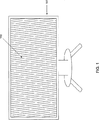
ステレオグラフィックスシンサグラム(StereoGraphics SynthaGram)(商標)は、図1に示されるようなディスプレイ表面に(普通、斜めに)レンチキュラ要素のアレイを装着して使用する自動立体視映像形成製品である。ウィンネク(Winnek)の米国特許第3,409,351号には、その斜め配置、すなわち、レンチキュラの軸をディスプレイの垂直端に対してある角度で傾かせるプロセスが記載されている。ステレオグラフィックスシンサグラム(StereoGraphics SynthaGram)(商標)に含まれる特別なソフトウェアでは、多重映像画像情報が、交互配置マッピング技法を用いて適切に配列されているので、当該ディスプレイを見ると、人は左目で左目映像の一つを見て、右目で右目映像の一つを見るようになる。この結果、特殊な眼鏡、鏡、または眼に装着して使用する他の立体視選択装置を使用する必要なく、映像を立体視する経験が得られる。 StereoGraphics SynthaGram (TM) is an autostereoscopic imaging product that is used with an array of lenticular elements (usually diagonally) on the display surface as shown in FIG. Winnek U.S. Pat. No. 3,409,351 describes its oblique arrangement, ie the process of tilting the lenticular axis at an angle with respect to the vertical edge of the display. The special software included in the StereoGraphics SynthaGram (TM) has multiple video image information properly arranged using an interleaved mapping technique, so that when viewing the display, a person is left To see one of the left-eye images and with the right eye to see one of the right-eye images. As a result, it is possible to obtain an experience of stereoscopically viewing an image without using special glasses, a mirror, or another stereoscopic selection device that is worn on the eye.
普通、ステレオグラフィックスシンサグラム(StereoGraphics SynthaGram)(商標)では、約9個の相異なるソース映像画像が提供され、各ソース映像画像は相異なる視点から得られたものを示し、これらを合成すると、自動的に立体視される映像シーンが得られる。これらのソース映像画像は、写真をソースとしたものでも、コンピュータグラフィックスをソースとしたものでもよく、また、事前に調製したものでも、またはリアルタイム(ディスプレイと実質的に同時)に得られるものでもよい。映像の数は、9個より多くとも少なくとも一般性は失われない。 Typically, StereoGraphics SynthaGram (TM) provides about 9 different source video images, each source video image showing what was obtained from different viewpoints, A video scene that is automatically stereoscopically viewed can be obtained. These source video images may be sourced from photographs, sourced from computer graphics, prepared in advance, or obtained in real time (substantially simultaneously with the display). Good. Even if the number of images exceeds 9, at least generality is not lost.
映像の交互配置に使用されるステレオグラフィックスシンサグラム(StereoGraphics SynthaGram)(商標)アルゴリズムは、インタージグ(Interzig;ジグザグ配置)と称され、これら二つの用語は、本開示では双方とも交換可能であり、同じ意味で使用される。画像交互配置プロセスは、先ず相異なるソース映像画像すべてからサブピクセル(サブピクセルとは、単一ピクセルの赤、緑、または青のコンポーネントのこと)を抽出し、次いでこれらのサブピクセルを適切に配列し、その結果として交互配置された画像を得るものである。例えば、ある特定のソース映像画像のサブピクセルは、そのサブピクセルが画像を視ている人の特定の視野ゾーンに対応するレンチキュラアレイの微小レンズ部分の下に現出すれば、インタージグされた画像にコピー可能となるのである。 The StereoGraphics SynthaGram (TM) algorithm used for video interleaving is called Interzig and these two terms are interchangeable in this disclosure Are used interchangeably. The image interleaving process first extracts subpixels from all the different source video images (a subpixel is a single pixel red, green, or blue component) and then arranges these subpixels appropriately. As a result, interleaved images are obtained. For example, if a sub-pixel of a particular source video image appears under the microlens portion of the lenticular array that corresponds to the particular viewing zone of the person viewing the image, then an interdigitated image It becomes possible to copy to.
前記画像交互配置プロセスは、光学ディスプレイの特性を理解した上でサブピクセルのマッピングを実行する。これら特性には、見る人と交互配置された画像との間の視距離は勿論のこと、レンチキュラアレイの物理的配置(ピッチ、傾き、オフセット)が含まれる。 The image interleaving process performs sub-pixel mapping after understanding the characteristics of the optical display. These characteristics include the physical placement (pitch, tilt, offset) of the lenticular array as well as the viewing distance between the viewer and the interleaved images.
最後に、インタージグされたサブピクセルデータがディスプレイ装置の実際のサブピクセルに送られ、さらにレンチキュラ微小レンズアレイを通過し、その結果、映像を自動的に立体視する経験が得られる。 Finally, the interdigitated sub-pixel data is sent to the actual sub-pixels of the display device and further passes through the lenticular microlens array, resulting in the experience of automatically stereoscopic viewing the video.
インタージグを実施するプロセスを加速するため、本発明のシステムは、ビューマップを作成し得る。前記ビューマップは、最終映像画像に現出する所与のサブピクセルに対するソースとして使用される具体的なソース映像画像を示ようにエンコードされる。そのようなビューマップの一例が、図3に示される。画像交互配置プロセスでは、従って、ソース映像画像、例えば、9個のソース映像画像が取り出され、これらを単一のビューマップにマッピングすることによって、画像交互配置プロセスを加速する。事前に計算されたビューマップを備えれば、どのソース映像画像を最終画像の所要のサブピクセルに使用すべきかを繰り返して計算する面倒さと計算時間とが節約される。一旦ソース映像画像が、図3に示されるようなビューマップをルックアップテーブルとして使用することによって、決定されてしまえば、本発明のシステムは、ビューマップ値が指し示すソース映像画像に属する適切な画像マップ位置にあるピクセルのカラー要素値に基づいて特定のサブピクセルの強度を決定し得る。 In order to accelerate the process of performing the inter jig, the system of the present invention may create a view map. The view map is encoded to indicate a specific source video image that is used as a source for a given subpixel that appears in the final video image. An example of such a view map is shown in FIG. The image interleaving process thus accelerates the image interleaving process by taking source video images, eg, nine source video images, and mapping them to a single view map. Providing a precomputed view map saves the hassle and computation time of repeatedly calculating which source video image should be used for the required subpixel of the final image. Once the source video image has been determined by using a view map as shown in FIG. 3 as a lookup table, the system of the present invention can select the appropriate image belonging to the source video image that the view map value points to. The intensity of a particular subpixel may be determined based on the color element value of the pixel at the map location.
ビューマップは、ピクセルマスキング法を含む別の相異なる実施方法を使用しても効率的に適用し得る。この場合、ビューマップは、ソース映像画像をフィルタ処理する一組のバイナリ形式マスクとピクセルを生成し、ピクセル毎計算が、グラフィックス装置のテクスチャに記憶されたビューマップを参照することによって、急速に実行される。 The view map can also be applied efficiently using other different implementation methods, including pixel masking methods. In this case, the view map generates a set of binary masks and pixels that filter the source video image, and the pixel-by-pixel calculation is rapidly performed by referring to the view map stored in the graphics device texture. Executed.
上記のような高速アルゴリズムを使用してさえ、極めて大きいビューマップを使用すると、性能にペナルティが課されことが起こり得る。上記のように、前記ビューマップは、作成される最終画像のフルサイズに対応する(また、より大きなセグメントのビデオメモリを占拠することもあり得る)。ビューマップと、恐らくそのビューマップが作成するバイナリ形式マスクとが、より小さくなり得るならば、本システムで必要とされるグラフィックスメモリが小さくなり、処理速度に係わる相当程度の便益が実現し得ることになる。処理速度に係わる便益は、一般に、限定的テクスチャメモリ内外でテクスチャを交換する時間が減少することから生ずる。適用次第であるが、追加的テクスチャは、ビジュアル効果(表面パターン)を得るのに使用し得る。ビューマップテクスチャは、これらの他のテクスチャと競合してメモリ空間を占める。例えば、3840×2400ピクセルのフルスクリーンサイズに対して作成される最終画像は、グラフィックス装置が2乗サイズという制約を有する場合、4096×4096のサイズの極めて大きなビューマップを必要とする。 Even using a fast algorithm as described above, using very large view maps can result in performance penalties. As mentioned above, the view map corresponds to the full size of the final image created (and may occupy a larger segment of video memory). If the view map and possibly the binary mask created by the view map can be smaller, the graphics memory required by the system can be reduced and a considerable benefit in terms of processing speed can be realized. It will be. The benefits associated with processing speed generally result from the reduced time to exchange textures in and out of limited texture memory. Depending on the application, additional textures can be used to obtain visual effects (surface patterns). Viewmap textures occupy memory space in competition with these other textures. For example, a final image created for a full screen size of 3840 × 2400 pixels will require a very large view map of 4096 × 4096 size if the graphics device has a square size constraint.
本発明の設計が求めることは、ビューマップ性能の問題と処理時間から生じるペナルティとを解決し、装置のスループットを増大するとともに、得られた自動立体視映像画像を見る人の楽しみを増やすことである。より効率的な方法で自動立体視ディスプレイのシステム内にビューマップを採用する設計、特に、以前に利用可能のものを超えた便益をもたらす設計を提供することは、有利なことであろう。 The design of the present invention seeks to solve view map performance problems and penalties resulting from processing time, increase the throughput of the device, and increase the enjoyment of the person viewing the resulting autostereoscopic image. is there. It would be advantageous to provide a design that employs a view map in an autostereoscopic display system in a more efficient manner, and in particular, a design that provides benefits beyond those previously available.
本発明の態様の一つに基づけば、自動立体視ソース映像画像の縮小サイズのビューマップを作成する方法が開示される。本方法は、ソース映像画像の値と始点ピクセルを含む複数のピクセル位置とから成る第一ビューマップに自動立体視ソース映像画像をマッピングする数学モデルを作成するステップと、前記第一ビューマップに前記自動立体視ソース映像画像をマッピングするステップと、前記第一ビューマップを走査してソース映像画像の値が始点ピクセルの値と近接的にマッチングする少なくとも一つのピクセル位置を得るステップと、マッチングされたピクセル位置を前記第一ビューマップ内に再生することによって縮小サイズのビューマップを作成するステップとを備える。 In accordance with one aspect of the present invention, a method for creating a reduced size view map of an autostereoscopic source video image is disclosed. The method includes creating a mathematical model for mapping an autostereoscopic source video image to a first view map comprising a value of the source video image and a plurality of pixel positions including a start pixel; and Mapping the autostereoscopic source video image; scanning the first view map to obtain at least one pixel position where the value of the source video image closely matches the value of the source pixel; and matched Creating a reduced size view map by reproducing pixel locations in the first view map.
本発明のこれらと他の利点は、本発明の以下の詳細な説明と添付の図面とから当業者には明白となろう。 These and other advantages of the invention will be apparent to those skilled in the art from the following detailed description of the invention and the accompanying drawings.
本開示は、レンチキュラ光学スクリーンを使用して視られる自動立体視画像に必要なソース映像画像を数学的に交互配置、すなわち、インタージグする方法をカバーする。図1は、レンチキュラ方式スクリーンが装着されたそのようなディスプレイを示す。ディスプレイ装置101は、フラットパネル型ディスプレイ装置であり、一方、スクリーン102は、微小レンズのアレイを備えるレンチキュラ方式スクリーンである。スクリーン102は、ユーザまたは見る人の視野ゾーンの相異なるセグメントに自動立体視映像の相異なるコンポーネントを導くためにディスプレイ表面上に設置される。
The present disclosure covers a method for mathematically interlacing, i.e., inter-jigging, the source video images required for autostereoscopic images viewed using a lenticular optical screen. FIG. 1 shows such a display fitted with a lenticular screen. The
図2は、ディスプレイ装置101のサブピクセルを覆うある一つの具体的なレンチクルの輪郭を示す。レンチクル201は、微小レンズアレイの中の一つのレンチクルである。ここでは、レンズ要素はスクリーンから面が外に凸であるが、別には、面が内に凹のものでもよい。サブピクセル202は、装置を構成するサブピクセルを表し、各サブピクセルは、1ドットの光を発する。現在製作されているフラットパネル型ディスプレイでは、これらの1ドット光を発する装置サブピクセルは各々、赤(R)、緑)G)、または青(B)のいずれか一つの情報を備える。ここで、サブピクセル202の本質的属性は、離散的で、しかも個々にアドレス可能な光のドットを表すものということであり、特に赤、緑、青であるということではない。将来のディスプレイは、例えば、多色カラーのドット要素のような相異なる種類のカラーまたは光の情報を伝えるディスプレイドット要素を配列し得るからである。領域203は、各レンチクルが9個のサブ領域に分割されている(この例では、自動立体視映像画像が9個のソース映像画像を使用するということを仮定する)ことを示す。ここでは、0〜8の番号が付けられ、適切なレンチクルサブ領域下に表され得るソース映像画像に対応している。例えば、真ん中のソース映像画像は、番号4で示され、そのデータは、レンチクルの真ん中のサブ領域の真下に配置されるのが好ましい。
FIG. 2 shows the outline of one specific lenticule that covers the sub-pixels of the
上記のように、本発明のシステムは、ソース映像画像のマップとして事前に計算されたビューマップを使用し、これをどのような所与のサブピクセルに対しても使用する。このビューマップをガイドとして実施される画像交互配置は、使用される特定のソース映像画像について繰り返し計算を行うことに基づく画像交互配置プロセスの場合に比較して、はるかに急速、かつ効率的に行われる。 As described above, the system of the present invention uses a pre-computed view map as the source video image map and uses it for any given sub-pixel. Image interleaving performed using this view map as a guide is much faster and more efficient than the image interleaving process based on iterative calculations for the particular source video image used. Is called.
図3は、そのようなビューマップの例を示す。領域301は、ビューマップが数のアレイであることを示す。単一ピクセル302は、ビューマップアレイの一部を示し、単一のピクセルを示す。同ピクセルは、この配置では3個のサブピクセルを備え、各サブピクセルはディスプレイ装置上のアドレス可能の離散的光点を示す。図示の装置では、サブピクセルのセットは、赤(R)、緑(G)、青(B)の各サブピクセルから成る。赤サブピクセル303は、特定の赤(R)サブピクセルのビューマップにおける位置を表す。ビューマップのこのメンバーに含まれている値は、たまたま0であるとし得るが、これは、対応する装置サブピクセルが、対応するソース映像画像#0からのグラフィック情報を含んでいなければならないということを示す。
FIG. 3 shows an example of such a view map.
実際には、この実施例の赤サブピクセル303に附随する値である0は、近似値、すなわち、その特定のサブピクセル位置の実際のソース映像画像の値の丸められた値のこともある。例えば、実際のソース映像画像の値は0.25であるかも知れない。すなわち、対応する装置サブピクセルは、理想的には、そのグラフィック情報をソース映像画像#0からソース映像画像#1までの間の1/4のところのソース映像画像から取得する必要があることを意味しているかも知れない。ソース映像画像#0とソース映像画像#1との間にはソース映像画像が存在しないので、サブピクセル位置に対するソース映像画像値は、0.25という実際の値から整数の0に必然的に丸められなければならない。
In practice, the
本設計は、向上した効率的タイル形式ビューマップ法をベースとし、マッピングされる最終の交互配置画像よりも格段に小さなサイズのビューマップに対する必要性に対処するものである。ビューマップは、フルサイズの画像よりも小さいので、最終画像の相異なるタイル、すなわち、部分に対して再使用できる。 This design is based on an improved efficient tiled view map method and addresses the need for a view map that is much smaller than the final interleaved image to be mapped. Since the view map is smaller than the full-size image, it can be reused for different tiles or portions of the final image.
必要とされる映像を効果的にマッピングする、より小さなサイズのビューマップを作成するには、ある一つのビューマップ、すなわち、第一ビューマップを作成するのに使用される数学モデルを取得するステップと、そのビューマップを走査してソース映像画像の値が始点ピクセルの値と近接的にマッチングするピクセル位置を得るステップとが必要がある。注記したいことは、前記ソース映像画像の値は、ここでは正確な値を示すものであって、ビューマップに記されることになるこの値の丸められた整数バージョンではないことである。ビューマップを生成するのに使用される数学モデルは、オフセット値のアレイから成る。普通、9個のソース映像画像が採用されるが、他の個数のソース映像画像も使用し得る。9個のソース映像画像の場合、最終のビューマップには、9個のソース映像画像の内の1個を指し示すサブピクセル各々が、レンチキュラ光学エレメントの下にあるそのサブピクセルの位置に基づいてマッピングされる。そのようなマッピングは、普通、ピクセルをディスプレイする最良の位置の近似に基づいているので、レンチキュラを通して見ると、見る人にはそのマッピングによって最適な映像視条件が得られる。例えば、ある特定のサブピクセル位置の計算で、4.3278というソース映像画像値が必要であると仮定すると、この値は4に丸められ、サブピクセル位置は4という値を受け取ることになる。すなわち、これは、ソース映像画像#4が、最終の交互配置された自動立体視映像画像でそのサブピクセルを表すのに使用されるということを意味する。
To create a smaller size view map that effectively maps the required video, get a single view map, the mathematical model used to create the first view map And scanning the view map to obtain a pixel position where the value of the source video image closely matches the value of the starting pixel. It should be noted that the value of the source video image is here an exact value, not a rounded integer version of this value that will be marked in the view map. The mathematical model used to generate the view map consists of an array of offset values. Normally, nine source video images are employed, but other numbers of source video images may be used. For nine source video images, the final view map maps each subpixel pointing to one of the nine source video images based on the position of that subpixel under the lenticular optical element. Is done. Such a mapping is usually based on an approximation of the best position to display the pixels, so that when viewed through a lenticular, the viewer can obtain optimal video viewing conditions. For example, assuming that the calculation of a particular subpixel location requires a source video image value of 4.3278, this value will be rounded to 4 and the subpixel location will receive a value of 4. That is, this means that source
所与のサブピクセル位置に対するソース映像画像の値を計算するには、普通、マッピング計算が伴われる。この計算では、レンチキュラのピッチ、傾斜、位置、その他の物理的属性に関する既知の値を使用して、所与のレンチキュラ要素のどの部分が特定のサブピクセルのグリッドの特定の位置の上に存在するかどうかが正確に決定される。この計算を行う方法はたくさんある。幾つかの方法では、与えられた行とスクリーン全体の新しい行の各々に含まれる新しいピクセルの各々に対するオフセット値を繰り返し加算する計算が含まれ、他の方法では、事前に較正された定数値で位置値を乗算する計算が含まれる。重要なことは、どのようにマッピングを計算するかではなく、得られたビューマップが結果として、スクリーン上の全範囲のサブピクセル位置上にレンチキュラ要素を位置合わせするように作成されるということである。上述したように、ビューマップ計算は、結果として丸められるのであるが、これは、実際の映像画像の数は、限定された数だけが利用可能であるということを反映しているのであって、このことは、ビューマップでは整数のソース映像画像値で示される。 Computing the value of the source video image for a given subpixel location usually involves a mapping calculation. This calculation uses known values for lenticular pitch, tilt, position, and other physical attributes, which part of a given lenticular element is above a specific position in a grid of specific subpixels Whether it is accurately determined. There are many ways to do this calculation. Some methods include calculations that repeatedly add an offset value for each new pixel contained in a given row and each new row in the entire screen, while other methods use pre-calibrated constant values. Includes calculations to multiply position values. What is important is not how the mapping is calculated, but that the resulting view map is created to align the lenticular elements over the full range of subpixel positions on the screen. is there. As mentioned above, the view map calculation is rounded as a result, which reflects that only a limited number of actual video images are available, This is indicated by an integer source video image value in the view map.
最終の交互配置された画像よりも小さなサイズのビューマップを使用するため、本システムでは、9個のソース映像画像中に繰り返しパターンの位置が探索される。本システムにおける繰り返しパターンの位置の探索は、ソース映像画像を走査して、フルサイズのビューマップ内で、そのようなフルサイズのビューマップの始点近くに見出される数字パターンに近接的にマッチングするそのような繰り返しパターンを探索するステップで行われる。つまり、始点の(一番最初の)サブピクセルが1.3000というソース映像画像値を有し、そして同じ行の(そして始点サブピクセルと同じカラー成分を示す)他の一つのサブピクセルが同様に1.3000というソース映像画像値(またはその値に極めて近接した値)を有する場合、その第二サブピクセルからスタートするビューマップ情報は冗長になるわけである。このような状況では、そのサブピクセル位置までの(フルサイズより小さい)ビューマップ情報のコピーを再使用して、そのサブピクセルの箇所でスタートし得る。 In order to use a smaller size view map than the final interleaved image, the system searches for the position of the repetitive pattern in the nine source video images. The search for the position of the repetitive pattern in this system involves scanning the source video image and matching it closely within the full-size view map to a numeric pattern found near the start of such full-size view map. This is performed in the step of searching for such a repeating pattern. That is, the starting (first) subpixel has a source video image value of 1.3000 and the other subpixel in the same row (and showing the same color component as the starting subpixel) is similarly If it has a source video image value of 1.3000 (or a value very close to that value), the view map information starting from that second subpixel is redundant. In such a situation, a copy of the view map information (less than full size) up to that subpixel location can be reused and started at that subpixel location.
注記したいのは、この点で採用されるソース映像画像の値、例えば、上記の例では1.3000に関しては、本システムでは、丸められた整数値ではなく、正確なソース映像画像値が使用されるということである。 Note that for the source video image values employed in this respect, eg 1.3000 in the above example, the system uses the exact source video image values rather than the rounded integer values. That is.
特定の軸(水平または垂直)に沿った最適なタイル寸法を見出すのに使用される一般アルゴリズムは、可能な誤差が最小となるようにその軸に沿って走査するステップを含む。上記の例では、誤差は1.3000−1.3000=0.0000となる。換言すれば、誤差とは、ピクセル間、例えば、隣接するピクセル間の映像画像値間の差を表すものである。通常、誤差ゼロは達成されないし、そのような完全なことは必要でもない。さらに多くは、誤差の値は、小数点以下の小さな値となる。これらの小数点以下の小さな誤差値は、次いで誤差が繰り返して生じる回数だけ掛け算され、総合誤差値が決定される。他の例を用いてみよう。最終画像の水平ピクセルのサイズが1600で、300のタイル寸法をテストしている場合、そのタイルのサイズでは一回タイル作製する毎に0.06の誤差値となると仮定する。この例の総合誤差は、実際に大略(1600/300×0.06)、つまり、約0.3となる。目的は、総合誤差が、得られる画像のフル領域に対して最小限に抑えられるタイル寸法を得るように、走査することである。 The general algorithm used to find the optimal tile size along a particular axis (horizontal or vertical) involves scanning along that axis so that the possible errors are minimized. In the above example, the error is 1.3000−1.3000 = 0.0000. In other words, the error represents a difference between video image values between pixels, for example, between adjacent pixels. Normally no error is achieved and such perfection is not necessary. In many cases, the error value is a small value after the decimal point. These small error values after the decimal point are then multiplied by the number of times the error occurs repeatedly to determine the total error value. Let's use another example. If the final image has a horizontal pixel size of 1600 and is testing 300 tile dimensions, it is assumed that the tile size results in an error value of 0.06 for each tile production. The total error in this example is actually approximately (1600/300 × 0.06), that is, about 0.3. The objective is to scan so that the total error is at a tile size that is minimized over the full area of the resulting image.
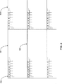
水平と垂直とから成る二次元に対しては、長方形面積のタイル作製スキームには二種類の一般クラスが存在する。すなわち、行間に水平オフセットが存在しないグリッド型配置と、行間にある幅の水平オフセットが存在する「レンガ」型配置である。グリッド型配置は図4に示され、作成は最も簡単であり、使用にも最も簡単である。図4では、タイル401は、画像エリアの表現図の上部左側のコーナーにあるタイルである。領域402は、このタイルが図3のものと同様なビューマップを含み、タイルのコーナーに始点を有していることを示す。タイル403は、画像エリアにある別個のタイル例である。注記したいのは、このタイルの始点が、タイル401に使用されているのと全く同一のビューマップデータを有していることである(ソース映像画像値はすべて{0,2,4,6,8,1.3,...}である)。このタイル例は、前のタイルから離れて位置する水平オフセットを有する。タイル404は、更なる他の一つのタイル例であり、他の一つのタイルの直下に現れている。注記したいのは、図4のタイルのフルセットがグリッド配置を形成するということである。結果として、本システムは、多重の領域から成るスクリーン域を有し、これらの領域が集合してグリッドを形成するのである。
For two dimensions, horizontal and vertical, there are two general classes of rectangular area tiling schemes. That is, a grid type arrangement in which there is no horizontal offset between rows and a “brick” type arrangement in which there is a horizontal offset with a width between rows. A grid-type arrangement is shown in FIG. 4 and is the simplest to create and simplest to use. In FIG. 4, a
これらの領域はすべて、同一または極めて同様な対応するソース映像画像値を有する。この実質的同一性により、本システムは比較的小さなビューマップを使用して全スクリーンのこれら極めて多くのタイル領域のいずれをも示すことが可能となるのである。 All of these regions have corresponding source video image values that are identical or very similar. This substantial identity allows the system to show any of these numerous tile areas of the entire screen using a relatively small view map.
グリッドのサイズを決定するということは、最適の水平タイル寸法を見出し、そして最適の垂直タイル寸法を見出すという問題である。ここで、最適とはその寸法に沿って総合誤差を最小限にすることを意味する。図5に示されるような、行の間に水平オフセットを備える「レンガ」型タイル配置の利点は、タイル位置が他のタイルの直上または直下に限定されないならば、より小さな総合誤差が垂直方向の次元に生じ得るということである。図5では、タイル501は画像エリアの表現図の上部左側コーナーにあるタイルである。領域502は、このタイルのビューマップを表し、タイルのコーナーにその始点を有する。タイル503は、画像エリアにある別個のタイル例であり、始点は、タイル501に使用のものと同一のビューマップデータを有する。タイル504は、次行に配置されるタイル例である。注記したいのは、タイル504が上の行にあるタイルの直下にはなく、かつ水平のオフセットがあるので、結果として「レンガ」を積んだ状態の配置になるということである。タイル505が示すのは、この「レンガ」型レイアウトを使うと、幾つかのタイルは、そのビューマップの始点が全体画像の始点に先行する箇所に結果として生じる、すなわち、部分的全体画像が提供されるということである。
Determining the size of the grid is a matter of finding the optimal horizontal tile dimensions and finding the optimal vertical tile dimensions. Here, optimal means minimizing the total error along that dimension. The advantage of a “brick” type tile arrangement with a horizontal offset between rows, as shown in FIG. 5, is that if the tile position is not limited to just above or directly below other tiles, a smaller overall error will be It can occur in a dimension. In FIG. 5, a
注記したいのは、図に示される例では、ピクセルマップ始点(ディスプレイ、ビューマップ、タイル作成スキーム、および最終画像に適用される)が、上部左側コーナーにあると仮定されていることである。同じ一般原理と操作方法が、相異なる座標スキーム、例えば、下部左側始点を有するスキームやレイアウトにも適用される。 Note that the example shown in the figure assumes that the pixel map starting point (applied to the display, view map, tiling scheme, and final image) is in the upper left corner. The same general principles and operating methods apply to different coordinate schemes, for example schemes and layouts with a lower left starting point.
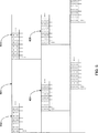
総合誤差値をさらに縮小するには、追加的技法を使用して達成し得る。すなわち、例えば、図6に示されているように、ビューマップのインデックスに付け加えられる増分値に基づいて、タイル化されたビューマップがソース映像画像を間接的に指し示すことを可能とする技法によって達成し得る。そのような追加的処理の支援があれば、本タイル作成スキームは完全に近い結果を達成し得る。 Further reduction of the overall error value can be achieved using additional techniques. That is, for example, as shown in FIG. 6, achieved by a technique that allows a tiled view map to indirectly point to the source video image based on an incremental value added to the view map index. Can do. With the support of such additional processing, the tile creation scheme can achieve near perfect results.
例えば、一つタイルが{1,2,3,4,5,...}のソース映像画像値を有し、他の一つのタイルが{3,4,5,6,7,...}のソース映像画像値を有すると仮定すると、後者のタイルは、各ソース映像画像値に2という値を追加しなければならないことを除いて、第一のビューマップに使用されたものと同一のビューマップで示し得る。この技法の利点は、この技法が、そのソース映像数のファクターだけ、可能なタイル作製スキームの数を増加し、従って、他のファクターはすべて同一で、最良のタイル作成スキーム(複数を含む)の精度を増す(誤差を最小化する)ことである。 For example, if one tile is {1, 2, 3, 4, 5,. . . } And the other tile is {3,4,5,6,7,. . . }, The latter tile is identical to that used for the first view map, except that a value of 2 must be added to each source video image value. Can be shown in view map. The advantage of this technique is that it increases the number of possible tiling schemes by a factor of its source video number, so all other factors are the same and the best tiling scheme (s) To increase accuracy (minimize errors).
さらに具体例を使用して説明しよう。図6にあるタイル601は、画像エリアの表現図の上部左側コーナーにあるタイルを示す。領域602は、タイル601のビューマップであり、0,2,4,6,8,1,3,...で(この例では)スタートする数の二次元アレイである。タイル603は、次のタイル例である。図6の例では、同じビューマップデータアレイ(すなわち、ここでも0,2,4,6,8,1,3,...でスタートする)を使用するけれども、各サブピクセルに対して、この例では、本システムは、4の値を加える。注記したいのは、もし合計がソース映像画像の総数(9)に等しいか、超えれば、本システムは、その数を引いてインデックス値を正規化することである。従って、このタイル603にあるピクセルは、ソース映像画像4+0,4+2,4+4,4+6−9,4+8−9,4+1,4+3,...を使用する。タイル604は、次ぎの行に位置するタイル例である。タイル603と同じように、本システムは、同じビューマップと関連データを使用するが、ここでは、次行のタイルを実装するのに相異なるオフセット因子(この例では、1である)を適用する。従って、この改良法では、少なくとも一つのオフセット因子を以降のタイルすべてに適用することになるので、ビューマップデータ処理の必要程度が減少しながらも、許容し得る総括映像視結果が得られる。
I will explain it using specific examples. A
タイル605は、タイル604から水平方向にオフセットして配置されたタイル例である。タイル605は、前記ビューマップデータを使用して、これらに、604でも使用された垂直のタイルオフセット値(1)を加え、タイル603で使用された水平のタイルオフセット値(4)を加えたデータアレイを有する。
The tile 605 is an example of a tile that is arranged offset from the
図6の例に示されるように、ビューマップの始点サブピクセルはソース映像画像#0を規定し得るが、これは、始点サブピクセルの一番最初のタイル位置に対しては正しい。しかし、始点サブピクセルの次の水平タイル位置に対しては、0というそのサブピクセルのビューマップ値は、オフセット値が、例えば、4というオフセット値が加えられたものとなる。従って、新しいタイル位置に対しては、ビューマップ値は、実際はソース映像画像#4(0+4)を規定する。次の水平のタイル位置に対しては、本システムは、4というオフセット値を加え、0+4+4=8とする。その後、本システムはさらに再び、4というオフセット値を加え、8+4=12という結果を出す。本システムは、ソース映像画像の数(ここでも、一般に9)を引算し、0〜8の許容し得る範囲内で値を正規化し、12−9=3とする。これは、本システムが今はソース映像画像#3を指し示すということを意味する。相異なるオフセット値を、ビューマップタイルの相異なる行の例に適用し得る。
As shown in the example of FIG. 6, the starting subpixel of the view map may define the source
ビューマップがタイル増分に基づいてソース映像画像を指し示すこのより良い方法を最適化するに当たって、最小化された誤差値は、最早{(あるサブピクセルに対して計算された非整数のソース映像値)―(始点サブピクセルのソース映像値)}ではない。代わりに、本システムは、任意のサブピクセルの計算されたソース映像値の少数部分と始点サブピクセルのソース映像値の少数部分との間の差を最小化することを狙うものである。最適化法を変更して、前記の数(0〜ソース映像画像の総数の範囲、一般に9)の少数部分をただ比較することにすると、最適化に必要な候補の選択性を顕著に改良し得る。 In optimizing this better way in which the view map points to the source video image based on the tile increment, the minimized error value is no longer {(a non-integer source video value calculated for a subpixel). -(Source video value of start point sub-pixel)}. Instead, the system aims to minimize the difference between the fractional portion of the calculated source video value of any subpixel and the source video value of the starting subpixel. By changing the optimization method and only comparing a small number of the above numbers (0 to the total number of source video images, generally 9), the selectivity of the candidates required for optimization is significantly improved. obtain.
交互配置された立体視映像画像は、全体の総タイル作製誤差が単一のソース映像画像に丸められる範囲の約5%以内ならば、シームレスと見ても許容し得る。実験したところ、増分されたインデックス値を使用してソース映像画像を指し示す直前記載の技法は、5%未満の総タイル作製誤差でタイル作製処理の結果を出すことができる。従って、タイル作製されたビューマップを使用することにより、本設計では、シームレスのように見える交互配置の立体視映像画像が作成され、同時にフルサイズのビューマップを使用するのに比較して、処理速度も大幅に改良される。 Interleaved stereoscopic video images can be considered seamless if the overall total tile creation error is within about 5% of the range rounded to a single source video image. Experiments have shown that the technique just described that uses an incremented index value to point to the source video image can produce a result of the tiling process with a total tiling error of less than 5%. Therefore, by using a tiled view map, this design creates an interleaved stereoscopic video image that looks seamless and at the same time processed compared to using a full-size view map. Speed is also greatly improved.
幾つかのケースでは、タイルの総数をある特定の最大限界内に維持することによって、追加的性能便益を導出し得る。より小さいビューマップサイズを有することで得られる処理時間の有利性よりも、計算のハードウェアや実施に左右されるのであるが、ビューマップを適用してディスプレイを完成するために必要な時間の方が優先することもあり得る。最適タイル作成スキームを見出すアルゴリズムは、修正を加えて、これや他の可能な制約に基づいてソリューションを制約し得る。 In some cases, additional performance benefits may be derived by keeping the total number of tiles within a certain maximum limit. The time required to complete the display by applying the view map, depending on the computational hardware and implementation, rather than the processing time advantage gained by having a smaller view map size May take precedence. An algorithm that finds the optimal tiling scheme can modify and constrain the solution based on this and other possible constraints.
タイル作成スキームを適用し得るにはその前に、そのようなスキームが、タイル作製仕様を構成する一組の数で記述される必要がある。その目的は、タイル作製スキームを比較的簡単なやり方で表し、自動立体視映像ディスプレイ向けに交互配置された画像をアセンブリするシステムが、ビューマップをスクリーンのタイル作製領域に正確に適用し得るようにすることである。ビューマップはフルサイズのスクリーンより小さいのはもちろんである。そのようなアセンブリを行うと、視覚的にシームレスな効果が得られ、フルサイズのスクリーン用ビューマップを使用した場合と同じ位良好なグラフィックスを自動立体視し得る。 Before a tiling scheme can be applied, such a scheme needs to be described by a set of numbers that make up the tiling specification. Its purpose is to represent the tiling scheme in a relatively simple manner so that a system that assembles interleaved images for autostereoscopic video displays can accurately apply the view map to the tiling area of the screen. It is to be. Of course, the view map is smaller than the full-size screen. Such an assembly provides a visually seamless effect and can autostereoscopic graphics as well as when using a full-size screen view map.
タイル作製仕様は幾つかの数字的コンポーネントを含む。第一に、ビューマップタイルは水平と垂直のピクセル次元を有する。本コンピュータシステムは、ビューマップタイルを追加して位置合わせするに当たって、前のタイルの直ぐ下と直ぐ左右に、水平と垂直の両方向に位置するように設定する。タイル作製方法が「レンガ」状タイル配置とするために次の行に水平オフセットを採用する場合、タイル作製仕様は、垂直列当たりの水平オフセットを規定する必要がある。タイル作製方法が、ビューマップで示された値に適用された増分に基づいてソース映像画像にアドレスするものならば、タイル作製仕様はその増分の具体的な量を示す必要がある。タイル作製仕様は、一般に、水平と垂直のタイル作製次元を規定するために相異なる増分を含み得る。タイル作製による誤差情報も、タイル作製仕様の一部として含まれ得る。結果が許容し得るかどうかを直ちに判断する目的だからである。例えば、5%のタイル作製誤差が許容可能ならば、タイル作製仕様に、この値を設定し、5%を超えるタイル作製誤差があれば、許容不可能なソリューションであると示し得る。 Tiling specifications include several numerical components. First, view map tiles have horizontal and vertical pixel dimensions. When the view map tile is added and aligned, the computer system is set to be positioned in both the horizontal and vertical directions immediately below and immediately to the left and right of the previous tile. If the tile fabrication method employs a horizontal offset in the next row to achieve a “brick” tile arrangement, the tile fabrication specification needs to define a horizontal offset per vertical column. If the tiling method addresses the source video image based on the increment applied to the value indicated in the view map, the tiling specification must indicate a specific amount of that increment. Tiling specifications can generally include different increments to define horizontal and vertical tiling dimensions. Error information due to tile fabrication may also be included as part of the tile fabrication specification. This is because the purpose is to immediately determine whether the result is acceptable. For example, if a 5% tile production error is acceptable, this value may be set in the tile production specification, and a tile production error greater than 5% may indicate an unacceptable solution.
本システムは、タイル作製スキームをプログラムに基づいて適用し、ビューマップタイル各個が、形成中の全体の交互配置画像を何処でオーバーレイするかを決定し得る。コンピュータまたはディスプレイ装置は、既に計算された特定のタイル作製仕様に基づいてタイルをレイアウトし得る。ソース映像増分がタイル作製モデル(例えば、図6に図示)の一部として使用される場合は、コンピュータまたはディスプレイ装置は、タイル作製モデルと仕様に基づいて正確にこれらの増分値を適用する必要がある。その適用に当たっては、普通、タイル作製仕様で示された水平と垂直の増分オフセット値に基づいて、各タイル位置に対して増分値を再計算する手順が含まれる。 The system can apply a tile creation scheme based on the program and determine where each individual view map tile overlays the entire interleaved image being formed. The computer or display device may lay out the tiles based on specific tile creation specifications that have already been calculated. If the source video increments are used as part of a tiling model (eg, as shown in FIG. 6), the computer or display device must apply these increments accurately based on the tiling model and specifications. is there. The application usually includes a procedure for recalculating the increment value for each tile position based on the horizontal and vertical incremental offset values indicated in the tile creation specification.
タイル作製仕様に関しては、コンピュータまたはディスプレイ装置は、これを現在のタイル作製スキームに適用するが、その適用は、一般に、実行中のタイル作製モデルに規定された制約条件に従ってどのようにタイルがレイアウトされるべきかという性質に関するルールに従う。簡単な例は、グリッド型タイル作製(ビューマップに増分を使用しない)である。グリッド型タイル作製シナリオでは、「ルール」は、最初のタイルをスクリーン始点に設置し、そして以降のタイルをすべて(水平と垂直)に設置し、全部が前のタイルと隣接するように配置することといえる。水平オフセットのタイルでは、タイル作製スキームとその実行は、さらに、行当たりの水平オフセットの値と水平オフセットの適用方法とを双方とも規定する必要がある。従って、タイル作製仕様は、対処される具体的なニーズと所望の性能または活性に高度に依存する。 With respect to tiling specifications, the computer or display device applies this to the current tiling scheme, which generally lays out how the tiles are laid out according to the constraints specified in the running tiling model. Follow rules about the nature of what to do. A simple example is grid tile creation (does not use increments in the view map). In a grid tile creation scenario, the “rule” is that the first tile is placed at the start of the screen, and all subsequent tiles are placed horizontally (vertically and vertically) so that they are all adjacent to the previous tile. It can be said. For horizontal offset tiles, the tiling scheme and its implementation must further specify both the horizontal offset value per row and the method of applying the horizontal offset. Thus, the tile production specifications are highly dependent on the specific needs addressed and the desired performance or activity.
本システムが、ビューマップ解釈のために増分値を使用するタイルに適用する場合(例えば、タイルの一つが1,2,3,...、次のタイルが3,4,5,...、最初のタイルから垂直に離れた次のタイルが7,8,9,...、としよう)、ルールセット設定し、それとともにそのルールセットに従う仕様をも定め、増分値が確実に簡単かつ正確に適用されるようにする。この機能を実行するために複数のルールセットを採用し得るが、水平方向と垂直方向に見出される各連続タイルに対して加算される水平増分と垂直増分とを備えるそのようなルールセットの一つも採用し得る。 When the system applies to tiles that use incremental values for view map interpretation (eg, one of the tiles is 1, 2, 3, ..., the next tile is 3, 4, 5, ...). Suppose the next tile vertically separated from the first tile is 7, 8, 9, ...), set the ruleset, and also define the specifications according to the ruleset, ensuring that the increment value is simple and To be applied accurately. Multiple rule sets may be employed to perform this function, but one such rule set with horizontal and vertical increments added for each successive tile found in the horizontal and vertical directions is also possible. Can be adopted.
本発明の設計は、一般に、どのような汎用高性能コンピュータ処理アーキテクチャまたはハードウェア上にでも実行し得るという意味ではハードウェアに独立である。本明細書に開示されるタイル形式ビューマップを使用する自動立体視映像画像交互配置処理は、当業者に一般に既知の汎用または特殊高性能コンピュータ上での処理をも網羅するものである。 The design of the present invention is generally hardware independent in the sense that it can be run on any general purpose high performance computer processing architecture or hardware. The autostereoscopic image interleaving process using the tiled view map disclosed herein also covers processing on a general purpose or special high performance computer generally known to those skilled in the art.
本明細書に提供された設計と、説明された具体的な態様は、限定を意味するのではなく、本発明、すなわち、視差補正の改良されたシステムと方法に関する教示と便益とを依然として備える別法のコンポーネントをも含むものである。従って、本発明は具体的な実施の形態に関連して説明されたけれども、本発明はさらに修正が可能であることも理解されるであろう。本発明のこの出願がカバーしようとするのは、本発明の原理に、一般に、従う本発明のどのような変形、使用、または適用であり、本発明に関連する技術内で行われる既知で慣行的な実際技術内にあって本開示から逸脱したものをも含む。 The designs provided herein and the specific aspects described are not meant to be limiting, but are still provided with the teachings and benefits of the present invention, i.e., improved systems and methods of parallax correction. It also includes a legal component. Thus, although the invention has been described with reference to specific embodiments, it will be understood that the invention is capable of further modifications. This application of the present invention is intended to cover any variation, use, or application of the present invention that generally follows the principles of the present invention and is known and practiced within the technology related to the present invention. That fall within the scope of this disclosure and that depart from this disclosure.
具体的な実施の形態に関わる前述の説明は、開示の一般特性を十分に明らかにしているものであるから、他の人も、現在の知識を適用することによって、本発明の一般概念に逸脱することなく多岐にわたる適用のためのシステムと方法を容易に修正および/または適応し得る。従って、そのような適応と修正は、開示された実施の形態の等価物の意味と範囲の内にある。本明細書に採用された用語または術語は、説明目的であり、限定のためではない。 The foregoing description of the specific embodiments sufficiently clarifies the general characteristics of the disclosure, so that others can deviate from the general concept of the present invention by applying current knowledge. Systems and methods for a wide variety of applications can be easily modified and / or adapted without doing so. Accordingly, such adaptations and modifications are within the meaning and scope of the equivalents of the disclosed embodiments. The terminology or terminology employed herein is for illustrative purposes and not for limitation.
Claims (20)
自動立体視映像ソース画像をフルサイズの第一ビューマップにマッピングする数学モデルを作成するステップと、
ソース映像画像の番号と始点ピクセルを含む複数のピクセル位置とを含む前記第一ビューマップに前記自動立体視映像ソース画像をマッピングするステップと、
前記第一ビューマップを走査して、始点ピクセル近くに見出される前記ソース映像画像の番号の数字パターンと近接的にマッチングする繰り返しパターンを探索するステップと、
マッチングされた前記繰り返しパターンを前記第一ビューマップ内に再生することによって前記縮小サイズのビューマップを作成するステップと、
を備え、
前記マッピングするステップにおける前記第一ビューマップでは前記ソース映像画像の番号として丸められていない値が使用され、前記縮小サイズのビューマップでは前記ソース映像画像の番号として整数値が用いられ、
前記繰り返しパターンを探索するステップは、当該繰り返しパターンを前記第一ビューマップに適用したときに生じる、隣接するピクセル間のソース映像画像の番号の誤差の総和が最小限になるように、当該繰り返しパターンの寸法を求めるステップを含む、自動立体視映像ソース画像の縮小サイズのビューマップを作成する方法。A method for creating a reduced size view map of an autostereoscopic video source image,
Creating a mathematical model that maps the autostereoscopic video source image to a full-size first view map;
Mapping the autostereoscopic video source image to the first view map including a source video image number and a plurality of pixel locations including a start pixel;
Scanning the first view map for a repetitive pattern that closely matches the number pattern of the number of the source video image found near the start pixel;
Creating the reduced size view map by replaying the matched repeating pattern in the first view map;
With
In the first view map in the mapping step, an unrounded value is used as the source video image number , and in the reduced size view map, an integer value is used as the source video image number ,
The step of searching for the repetitive pattern includes the repetitive pattern so that a sum of errors in the numbers of source video images between adjacent pixels generated when the repetitive pattern is applied to the first view map is minimized. A method for creating a reduced size view map of an autostereoscopic video source image, comprising the step of:
ソース映像画像の番号と始点ピクセルを含む複数のピクセル位置とを含むフルサイズの第一ビューマップに前記自動立体視映像ソース画像をマッピングするステップと、
前記第一ビューマップを走査して、始点ピクセル近くに見出される前記ソース映像画像の番号の数字パターンと近接的にマッチングする繰り返しパターンを探索するステップと、
マッチングされた前記繰り返しパターンを前記第一ビューマップ内に再生することによって前記縮小サイズのビューマップを作成するステップと、
を備え、
前記マッピングするステップにおける前記第一ビューマップでは前記ソース映像画像の番号として丸められていない値が使用され、前記縮小サイズのビューマップでは前記ソース映像画像の番号として整数値が用いられ、
前記繰り返しパターンを探索するステップは、当該繰り返しパターンを前記第一ビューマップに適用したときに生じる、隣接するピクセル間のソース映像画像の番号の誤差の総和が最小限になるように、当該繰り返しパターンの寸法を求めるステップを含む、自動立体視映像ソース画像の縮小サイズのビューマップを作成する、自動立体視ソース画像の縮小サイズのビューマップを作成する方法。A method for creating a reduced size view map of an autostereoscopic video source image,
Mapping the autostereoscopic video source image to a full-size first view map including a source video image number and a plurality of pixel locations including a start pixel;
Scanning the first view map for a repetitive pattern that closely matches the number pattern of the number of the source video image found near the start pixel;
Creating the reduced size view map by replaying the matched repeating pattern in the first view map;
With
In the first view map in the mapping step, an unrounded value is used as the source video image number , and in the reduced size view map, an integer value is used as the source video image number ,
The step of searching for the repetitive pattern includes the repetitive pattern so that a sum of errors in the numbers of source video images between adjacent pixels generated when the repetitive pattern is applied to the first view map is minimized. A method for creating a reduced size view map of an autostereoscopic source image, comprising: generating a reduced size view map of the autostereoscopic video source image, the method including the step of determining a dimension of the autostereoscopic source image.
前記自動立体視映像ソース画像を多重ソース画像に分割するステップと、
前記自動立体視映像ソース画像に基づいてフルサイズの第一ビューマップを作成するステップと、
前記多重ソース画像を走査することによって前記多重ソース画像中に繰り返しパターンの位置を探索して前記フルサイズのビューマップの始点近くに見出される数のパターンに近接的にマッチングするサブピクセルの数パターンを有する少なくとも一つのサブピクセルを得るステップと、
そのサブピクセルの箇所でスタートするそのサブピクセル位置までビューマップ情報のコピーを再利用して縮小サイズのビューマップを作成するステップと、
を備え、
前記少なくとも一つのサブピクセルを得るステップではソース映像画像の番号として丸められていない値が使用され、前記縮小サイズのビューマップでは前記ソース映像画像の番号として整数値が用いられ、
前記少なくとも一つのサブピクセルを得るステップは、前記繰り返しパターンを前記第一ビューマップに適用したときに生じる、隣接するピクセル間のソース映像画像の番号の誤差の総和が最小限になるように、当該繰り返しパターンの寸法を求めるステップを含む、自動立体視映像ソース画像の縮小サイズのビューマップを作成する方法。A method for creating a reduced size view map of an autostereoscopic video source image,
Dividing the autostereoscopic video source image into multiple source images;
Creating a full-size first view map based on the autostereoscopic video source image;
By scanning the multi-source image, it searches for the position of the repetitive pattern in the multi-source image and finds a number pattern of sub-pixels that closely matches the number of patterns found near the starting point of the full-size view map. Obtaining at least one sub-pixel having:
Reclaiming a copy of the viewmap information to the subpixel location starting at that subpixel location to create a reduced size viewmap;
With
Wherein at least in the step of obtaining a single sub-pixel value is used unrounded as number of the source video image, the view map of the reduced size integer value is used as the number of the source video image,
The step of obtaining the at least one sub-pixel minimizes the sum of errors in the number of source video images between adjacent pixels that occurs when the repeating pattern is applied to the first view map. A method of creating a reduced size view map of an autostereoscopic video source image, including the step of determining a dimension of a repetitive pattern.
Applications Claiming Priority (3)
| Application Number | Priority Date | Filing Date | Title |
|---|---|---|---|
| US66559705P | 2005-03-26 | 2005-03-26 | |
| US60/665,597 | 2005-03-26 | ||
| PCT/US2006/010758 WO2006104878A2 (en) | 2005-03-26 | 2006-03-24 | Tiled view-maps for autostereoscopic interdigitation |
Publications (3)
| Publication Number | Publication Date |
|---|---|
| JP2008535389A JP2008535389A (en) | 2008-08-28 |
| JP2008535389A5 JP2008535389A5 (en) | 2012-08-16 |
| JP5070198B2 true JP5070198B2 (en) | 2012-11-07 |
Family
ID=37053933
Family Applications (1)
| Application Number | Title | Priority Date | Filing Date |
|---|---|---|---|
| JP2008504190A Expired - Fee Related JP5070198B2 (en) | 2005-03-26 | 2006-03-24 | How to create a reduced size view map of an autostereoscopic video source image |
Country Status (4)
| Country | Link |
|---|---|
| US (1) | US7570260B2 (en) |
| EP (1) | EP1869660A4 (en) |
| JP (1) | JP5070198B2 (en) |
| WO (1) | WO2006104878A2 (en) |
Families Citing this family (23)
| Publication number | Priority date | Publication date | Assignee | Title |
|---|---|---|---|---|
| WO2006104878A2 (en) * | 2005-03-26 | 2006-10-05 | Real D | Tiled view-maps for autostereoscopic interdigitation |
| US7652674B2 (en) * | 2006-02-09 | 2010-01-26 | Real D | On the fly hardware based interdigitation |
| US20110037830A1 (en) * | 2008-04-24 | 2011-02-17 | Nokia Corporation | Plug and play multiplexer for any stereoscopic viewing device |
| USD624952S1 (en) | 2008-10-20 | 2010-10-05 | X6D Ltd. | 3D glasses |
| USD666663S1 (en) | 2008-10-20 | 2012-09-04 | X6D Limited | 3D glasses |
| USD603445S1 (en) | 2009-03-13 | 2009-11-03 | X6D Limited | 3D glasses |
| USRE45394E1 (en) | 2008-10-20 | 2015-03-03 | X6D Limited | 3D glasses |
| CA2684513A1 (en) | 2008-11-17 | 2010-05-17 | X6D Limited | Improved performance 3d glasses |
| US8542326B2 (en) | 2008-11-17 | 2013-09-24 | X6D Limited | 3D shutter glasses for use with LCD displays |
| US20100245999A1 (en) * | 2009-03-30 | 2010-09-30 | Carlow Richard A | Cart For 3D Glasses |
| USD646451S1 (en) | 2009-03-30 | 2011-10-04 | X6D Limited | Cart for 3D glasses |
| USD650956S1 (en) | 2009-05-13 | 2011-12-20 | X6D Limited | Cart for 3D glasses |
| USD672804S1 (en) | 2009-05-13 | 2012-12-18 | X6D Limited | 3D glasses |
| USD671590S1 (en) | 2010-09-10 | 2012-11-27 | X6D Limited | 3D glasses |
| USD669522S1 (en) | 2010-08-27 | 2012-10-23 | X6D Limited | 3D glasses |
| USD692941S1 (en) | 2009-11-16 | 2013-11-05 | X6D Limited | 3D glasses |
| USD662965S1 (en) | 2010-02-04 | 2012-07-03 | X6D Limited | 3D glasses |
| USD664183S1 (en) | 2010-08-27 | 2012-07-24 | X6D Limited | 3D glasses |
| EP2461238B1 (en) | 2010-12-02 | 2017-06-28 | LG Electronics Inc. | Image display apparatus including an input device |
| US9363504B2 (en) * | 2011-06-23 | 2016-06-07 | Lg Electronics Inc. | Apparatus and method for displaying 3-dimensional image |
| USD711959S1 (en) | 2012-08-10 | 2014-08-26 | X6D Limited | Glasses for amblyopia treatment |
| EP3687168A1 (en) | 2019-01-24 | 2020-07-29 | Ultra-D Coöperatief U.A. | Assigning view numbers to display elements of an autostereoscopic display |
| WO2024009134A1 (en) * | 2022-07-08 | 2024-01-11 | Visutek 3D Gmbh | Method for generating an interlacing mapping |
Family Cites Families (19)
| Publication number | Priority date | Publication date | Assignee | Title |
|---|---|---|---|---|
| GB2297876A (en) * | 1995-02-09 | 1996-08-14 | Sharp Kk | Observer tracking autostereoscopic display |
| GB9513658D0 (en) * | 1995-07-05 | 1995-09-06 | Philips Electronics Uk Ltd | Autostereoscopic display apparatus |
| GB9611939D0 (en) * | 1996-06-07 | 1996-08-07 | Philips Electronics Nv | Stereoscopic image display driver apparatus |
| CA2275397C (en) * | 1996-12-18 | 2007-05-08 | Technische Universitat Dresden | Method and device for the three-dimensional representation of information |
| US6091482A (en) * | 1997-05-22 | 2000-07-18 | Reynolds Metals Company | Method of mapping and interlacing images to a lenticular lens |
| GB9715397D0 (en) * | 1997-07-23 | 1997-09-24 | Philips Electronics Nv | Lenticular screen adaptor |
| DE19827590C2 (en) * | 1998-06-20 | 2001-05-03 | Christoph Grosmann | Method and device for autostereoscopy |
| FR2782438B1 (en) * | 1998-08-13 | 2002-01-04 | Pierre Allio | AUTOSTEREOSCOPIC DISPLAY METHOD AND AUTOSTEREOSCOPIC IMAGE |
| GB0003311D0 (en) * | 2000-02-15 | 2000-04-05 | Koninkl Philips Electronics Nv | Autostereoscopic display driver |
| US7671889B2 (en) * | 2000-06-07 | 2010-03-02 | Real D | Autostereoscopic pixel arrangement techniques |
| EP1412803A2 (en) * | 2001-07-13 | 2004-04-28 | Mems Optical, Inc. | Autostereoscopic display with rotated microlens-array and method of displaying multidimensional images, especially color images |
| AU2002952874A0 (en) * | 2002-11-25 | 2002-12-12 | Dynamic Digital Depth Research Pty Ltd | 3D image synthesis from depth encoded source view |
| US8933945B2 (en) * | 2002-11-27 | 2015-01-13 | Ati Technologies Ulc | Dividing work among multiple graphics pipelines using a super-tiling technique |
| US20050012814A1 (en) * | 2003-07-17 | 2005-01-20 | Hsiao-Pen Shen | Method for displaying multiple-view stereoscopic images |
| DE10339076B4 (en) * | 2003-08-26 | 2007-10-31 | Seereal Technologies Gmbh | Autostereoscopic multi-user display |
| US7857700B2 (en) * | 2003-09-12 | 2010-12-28 | Igt | Three-dimensional autostereoscopic image display for a gaming apparatus |
| KR100728777B1 (en) * | 2004-04-07 | 2007-06-19 | 삼성에스디아이 주식회사 | Parallax barrier and three-dimensional display device using the same |
| US7787009B2 (en) * | 2004-05-10 | 2010-08-31 | University Of Southern California | Three dimensional interaction with autostereoscopic displays |
| WO2006104878A2 (en) * | 2005-03-26 | 2006-10-05 | Real D | Tiled view-maps for autostereoscopic interdigitation |
-
2006
- 2006-03-24 WO PCT/US2006/010758 patent/WO2006104878A2/en active Search and Examination
- 2006-03-24 JP JP2008504190A patent/JP5070198B2/en not_active Expired - Fee Related
- 2006-03-24 EP EP06739507A patent/EP1869660A4/en not_active Withdrawn
- 2006-03-24 US US11/388,352 patent/US7570260B2/en not_active Expired - Fee Related
Also Published As
| Publication number | Publication date |
|---|---|
| WO2006104878A2 (en) | 2006-10-05 |
| US20060279580A1 (en) | 2006-12-14 |
| JP2008535389A (en) | 2008-08-28 |
| WO2006104878A3 (en) | 2008-07-03 |
| US7570260B2 (en) | 2009-08-04 |
| EP1869660A2 (en) | 2007-12-26 |
| EP1869660A4 (en) | 2010-08-04 |
Similar Documents
| Publication | Publication Date | Title |
|---|---|---|
| JP5070198B2 (en) | How to create a reduced size view map of an autostereoscopic video source image | |
| US11269244B2 (en) | System and method for calibrating a display system using manual and semi-manual techniques | |
| US8953241B2 (en) | Autostereoscopic display apparatus and method | |
| US7652674B2 (en) | On the fly hardware based interdigitation | |
| JP4521342B2 (en) | 3D image display device, 3D image display method, and 3D image display program | |
| JP4950293B2 (en) | Autostereoscopic system | |
| JP2008535389A5 (en) | ||
| CN106604018B (en) | 3D display device and control method thereof | |
| US7511716B2 (en) | High-resolution micro-lens 3D display with shared sub-pixel color signals | |
| US9349073B2 (en) | Apparatus and method for image matching between multiview cameras | |
| JP2005309374A (en) | Three-dimensional display | |
| US20050083400A1 (en) | Three-dimensional image display device, three-dimensional image display method and three-dimensional display image data generating method | |
| US20120223941A1 (en) | Image display apparatus, method, and recording medium | |
| WO2019076314A1 (en) | Three-dimensional display panel and display device | |
| JP3770459B2 (en) | Image display device, image display method, and recording medium | |
| JP2008083600A (en) | Display control device, three-dimensional image display apparatus and program | |
| JP5696107B2 (en) | Image processing apparatus, method, program, and stereoscopic image display apparatus | |
| KR102463170B1 (en) | Apparatus and method for displaying three dimensional image | |
| JP7149615B2 (en) | Image display device, image display method, and image display system | |
| JP6626367B2 (en) | Stereoscopic image adjustment device and stereoscopic image adjustment method | |
| JP4107675B2 (en) | Image display device, image display method, and recording medium | |
| WO2013027280A1 (en) | Image processing apparatus, method therefor, and three-dimensional image display apparatus | |
| CN115588395A (en) | Compensation method and compensation device of display panel |
Legal Events
| Date | Code | Title | Description |
|---|---|---|---|
| A621 | Written request for application examination |
Free format text: JAPANESE INTERMEDIATE CODE: A621 Effective date: 20090126 |
|
| RD02 | Notification of acceptance of power of attorney |
Free format text: JAPANESE INTERMEDIATE CODE: A7422 Effective date: 20090422 |
|
| RD04 | Notification of resignation of power of attorney |
Free format text: JAPANESE INTERMEDIATE CODE: A7424 Effective date: 20090520 |
|
| A977 | Report on retrieval |
Free format text: JAPANESE INTERMEDIATE CODE: A971007 Effective date: 20110303 |
|
| A131 | Notification of reasons for refusal |
Free format text: JAPANESE INTERMEDIATE CODE: A131 Effective date: 20110315 |
|
| A521 | Request for written amendment filed |
Free format text: JAPANESE INTERMEDIATE CODE: A523 Effective date: 20110614 |
|
| A02 | Decision of refusal |
Free format text: JAPANESE INTERMEDIATE CODE: A02 Effective date: 20110830 |
|
| A521 | Request for written amendment filed |
Free format text: JAPANESE INTERMEDIATE CODE: A523 Effective date: 20120104 |
|
| A911 | Transfer to examiner for re-examination before appeal (zenchi) |
Free format text: JAPANESE INTERMEDIATE CODE: A911 Effective date: 20120113 |
|
| A131 | Notification of reasons for refusal |
Free format text: JAPANESE INTERMEDIATE CODE: A131 Effective date: 20120131 |
|
| A601 | Written request for extension of time |
Free format text: JAPANESE INTERMEDIATE CODE: A601 Effective date: 20120426 |
|
| A602 | Written permission of extension of time |
Free format text: JAPANESE INTERMEDIATE CODE: A602 Effective date: 20120508 |
|
| A601 | Written request for extension of time |
Free format text: JAPANESE INTERMEDIATE CODE: A601 Effective date: 20120530 |
|
| A602 | Written permission of extension of time |
Free format text: JAPANESE INTERMEDIATE CODE: A602 Effective date: 20120606 |
|
| A524 | Written submission of copy of amendment under article 19 pct |
Free format text: JAPANESE INTERMEDIATE CODE: A524 Effective date: 20120627 |
|
| TRDD | Decision of grant or rejection written | ||
| A01 | Written decision to grant a patent or to grant a registration (utility model) |
Free format text: JAPANESE INTERMEDIATE CODE: A01 Effective date: 20120724 |
|
| A01 | Written decision to grant a patent or to grant a registration (utility model) |
Free format text: JAPANESE INTERMEDIATE CODE: A01 |
|
| A61 | First payment of annual fees (during grant procedure) |
Free format text: JAPANESE INTERMEDIATE CODE: A61 Effective date: 20120820 |
|
| FPAY | Renewal fee payment (event date is renewal date of database) |
Free format text: PAYMENT UNTIL: 20150824 Year of fee payment: 3 |
|
| R150 | Certificate of patent or registration of utility model |
Free format text: JAPANESE INTERMEDIATE CODE: R150 |
|
| R250 | Receipt of annual fees |
Free format text: JAPANESE INTERMEDIATE CODE: R250 |
|
| R250 | Receipt of annual fees |
Free format text: JAPANESE INTERMEDIATE CODE: R250 |
|
| LAPS | Cancellation because of no payment of annual fees |