JP5065263B2 - How to mold a lens - Google Patents
How to mold a lens Download PDFInfo
- Publication number
- JP5065263B2 JP5065263B2 JP2008516396A JP2008516396A JP5065263B2 JP 5065263 B2 JP5065263 B2 JP 5065263B2 JP 2008516396 A JP2008516396 A JP 2008516396A JP 2008516396 A JP2008516396 A JP 2008516396A JP 5065263 B2 JP5065263 B2 JP 5065263B2
- Authority
- JP
- Japan
- Prior art keywords
- resin
- cavity
- lens
- molding
- transparent
- Prior art date
- Legal status (The legal status is an assumption and is not a legal conclusion. Google has not performed a legal analysis and makes no representation as to the accuracy of the status listed.)
- Expired - Fee Related
Links
Images


Classifications
-
- B—PERFORMING OPERATIONS; TRANSPORTING
- B29—WORKING OF PLASTICS; WORKING OF SUBSTANCES IN A PLASTIC STATE IN GENERAL
- B29D—PRODUCING PARTICULAR ARTICLES FROM PLASTICS OR FROM SUBSTANCES IN A PLASTIC STATE
- B29D11/00—Producing optical elements, e.g. lenses or prisms
-
- B—PERFORMING OPERATIONS; TRANSPORTING
- B29—WORKING OF PLASTICS; WORKING OF SUBSTANCES IN A PLASTIC STATE IN GENERAL
- B29D—PRODUCING PARTICULAR ARTICLES FROM PLASTICS OR FROM SUBSTANCES IN A PLASTIC STATE
- B29D11/00—Producing optical elements, e.g. lenses or prisms
- B29D11/00009—Production of simple or compound lenses
- B29D11/00432—Auxiliary operations, e.g. machines for filling the moulds
-
- B—PERFORMING OPERATIONS; TRANSPORTING
- B29—WORKING OF PLASTICS; WORKING OF SUBSTANCES IN A PLASTIC STATE IN GENERAL
- B29C—SHAPING OR JOINING OF PLASTICS; SHAPING OF MATERIAL IN A PLASTIC STATE, NOT OTHERWISE PROVIDED FOR; AFTER-TREATMENT OF THE SHAPED PRODUCTS, e.g. REPAIRING
- B29C33/00—Moulds or cores; Details thereof or accessories therefor
- B29C33/30—Mounting, exchanging or centering
-
- B—PERFORMING OPERATIONS; TRANSPORTING
- B29—WORKING OF PLASTICS; WORKING OF SUBSTANCES IN A PLASTIC STATE IN GENERAL
- B29C—SHAPING OR JOINING OF PLASTICS; SHAPING OF MATERIAL IN A PLASTIC STATE, NOT OTHERWISE PROVIDED FOR; AFTER-TREATMENT OF THE SHAPED PRODUCTS, e.g. REPAIRING
- B29C33/00—Moulds or cores; Details thereof or accessories therefor
- B29C33/38—Moulds or cores; Details thereof or accessories therefor characterised by the material or the manufacturing process
- B29C33/40—Plastics, e.g. foam or rubber
-
- B—PERFORMING OPERATIONS; TRANSPORTING
- B29—WORKING OF PLASTICS; WORKING OF SUBSTANCES IN A PLASTIC STATE IN GENERAL
- B29D—PRODUCING PARTICULAR ARTICLES FROM PLASTICS OR FROM SUBSTANCES IN A PLASTIC STATE
- B29D11/00—Producing optical elements, e.g. lenses or prisms
- B29D11/00009—Production of simple or compound lenses
- B29D11/00413—Production of simple or compound lenses made by moulding between two mould parts which are not in direct contact with one another, e.g. comprising a seal between or on the edges
-
- B—PERFORMING OPERATIONS; TRANSPORTING
- B29—WORKING OF PLASTICS; WORKING OF SUBSTANCES IN A PLASTIC STATE IN GENERAL
- B29D—PRODUCING PARTICULAR ARTICLES FROM PLASTICS OR FROM SUBSTANCES IN A PLASTIC STATE
- B29D11/00—Producing optical elements, e.g. lenses or prisms
- B29D11/00009—Production of simple or compound lenses
- B29D11/0048—Moulds for lenses
- B29D11/00528—Consisting of two mould halves joined by an annular gasket
-
- B—PERFORMING OPERATIONS; TRANSPORTING
- B29—WORKING OF PLASTICS; WORKING OF SUBSTANCES IN A PLASTIC STATE IN GENERAL
- B29D—PRODUCING PARTICULAR ARTICLES FROM PLASTICS OR FROM SUBSTANCES IN A PLASTIC STATE
- B29D11/00—Producing optical elements, e.g. lenses or prisms
- B29D11/00009—Production of simple or compound lenses
- B29D11/0048—Moulds for lenses
- B29D11/00557—Moulds for lenses with deformable mould walls, e.g. to make lenses with different shapes
Description
本発明は、レンズを成形する方法に関する。本発明は、特に、成形キャビティ(mould cavity)の形状が少なくとも1枚の柔軟なシートによって特徴付けられるレンズを成形す
る方法に関する。
The present invention relates to a method of molding a lens. The invention relates in particular to a method of molding a lens in which the shape of the mold cavity is characterized by at least one flexible sheet.
眼のレンズは、一般にプラスチック素材から作られる。そのプロセスは、いわゆる「レンズブランク」の成形に始まる。ここで、このレンズブランクの1つの表面(通常は前面)は、カーブ状(通常は球状)に形成される。前記カーブは、既知の光学パワーを前記レンズブランクに与える。その後、前記レンズブランクの他の表面を研削および研磨して、必要とする全体的な光学パワーをレンズに提供する。 Eye lenses are generally made from plastic materials. The process begins with the formation of a so-called “lens blank”. Here, one surface (usually the front surface) of the lens blank is formed in a curved shape (usually spherical). The curve imparts a known optical power to the lens blank. The other surface of the lens blank is then ground and polished to provide the lens with the required overall optical power.
一般的な形状では、成形されたレンズブランクの前面のカーブは、+6ジオプトリーである。+6未満のジオプトリーの処方レンズについては、その後、その後面を適切に研削することによって製造することができる。例えば、+2のジオプトリー処方が必要であるならば、−4のジオプトリー・カーブを後面に研削する。−2のジオプトリー処方が必要であるならば、−8のジオプトリー・カーブを研削する。 In a typical shape, the front curve of the molded lens blank is +6 diopters. A diopter prescription lens of less than +6 can then be manufactured by appropriately grinding the subsequent surface. For example, if a +2 diopter prescription is required, a -4 diopter curve is ground to the back. If a diopter recipe of -2 is required, grind the diopter curve of -8.
このようなレンズ製造プロセスは、一般的に使われるものの、前記レンズの前面及び後面を2つの異なった段階で形成することから極めて多くの時間を要する。特にこれらの段階のうち2番目の段階(レンズの後面を研削および研磨する段階)は極めて面倒である。加えて、前記レンズブランクを成形する段階は、光学品質の高い成形型(または、少なくとも、光学品質の高い前記レンズブランクの前面を形成する部分)を必要とする。また、そのような成形型の製造が、高価である場合がある。 Although such a lens manufacturing process is commonly used, it takes a great deal of time because the front and back surfaces of the lens are formed in two different stages. In particular, the second of these steps (the step of grinding and polishing the rear surface of the lens) is extremely troublesome. In addition, the step of molding the lens blank requires a mold having high optical quality (or at least a portion forming the front surface of the lens blank having high optical quality). Also, the production of such a mold may be expensive.
本発明の第一の態様によって、透明な樹脂から視力矯正用レンズを成形する方法が提供される。本方法は、以下の段階を含む:
レンズを成形する成形キャビティであって、該レンズの前面及び後面に対応する該成形キャビティの側面が2つのシートにより形成され、かつ該シートのうち少なくとも1つが柔軟である成形キャビティを用意する段階;
前記成形キャビティを透明な樹脂で満たす段階;
前記シートによって特徴付けられる前記レンズの形状が所望のパワーを提供するよう、前記キャビティ中の樹脂の量を調整して、前記柔軟なシートを変形させる段階;および、
前記樹脂を硬化する段階。
According to the first aspect of the present invention, there is provided a method of molding a vision correction lens from a transparent resin. The method includes the following steps:
Providing a molding cavity for molding a lens, the side of the molding cavity corresponding to the front and rear surfaces of the lens being formed by two sheets, and at least one of the sheets being flexible;
Filling the molding cavity with a transparent resin;
Adjusting the amount of resin in the cavity to deform the flexible sheet such that the shape of the lens characterized by the sheet provides the desired power; and
Curing the resin;
この方法は、レンズ成形の手順を大幅に単純化する。前記レンズの両面は、上で示したように2段階の手順を必要とするというより、むしろ単一の段階で生産することができる。さらに、光学品質の高い成形型を用意する必要がないことから、コストを下げることができる。 This method greatly simplifies the lens molding procedure. Both sides of the lens can be produced in a single stage rather than requiring a two stage procedure as indicated above. Furthermore, since it is not necessary to prepare a mold having high optical quality, the cost can be reduced.
前記シートが、透明であると好ましい。かかる場合には、前記レンズの形状及びパワーを最終使用者の視力に合わせて適合させることができるよう、該レンズの該最終使用者が前記透明なシート及び前記樹脂を通して見ている間に、前記キャビティ中の樹脂の量を調整して、前記柔軟なシートを変形させることができる。これにより、レンズを、個人の特定の要求に合わせて前記レンズを「調整する」ことが可能となるにもかかわらず、比較的安価に製造することができる。 The sheet is preferably transparent. In such a case, while the end user of the lens is looking through the transparent sheet and the resin, the shape and power of the lens can be adapted to match the eyesight of the end user. The flexible sheet can be deformed by adjusting the amount of resin in the cavity. This allows the lens to be manufactured at a relatively low cost, despite the fact that it can be “tuned” to the specific needs of the individual.
好ましい態様では、前記成形キャビティは、眼鏡などの光学装置中に用意される。そして、前記レンズは、「本来の場所に(in situ)」効果的に形成することができる。
2つのそのような成形キャビティが、眼鏡などの光学装置中に用意されると好ましい。これにより、使用者の両目の矯正を提供する眼鏡の製造を単純化することができる。
In a preferred embodiment, the molding cavity is provided in an optical device such as eyeglasses. The lens can then be effectively formed “in situ”.
Two such molding cavities are preferably provided in an optical device such as glasses. This can simplify the production of eyeglasses that provide correction for both eyes of the user.
代わりの好ましい方法では、第2のキャビティが用意される。ここで、前記第2のキャビティは、前記成形キャビティと同様のものであって、透明なシートから形成された前面および後面を有している。また、前記シートのうち少なくとも1つは柔軟であり、前記第2のキャビティの前記シートの柔軟性等は、前記成形キャビティ中の対応するシートの柔軟性等と同等であり、かつ、前記キャビティは透明な液体で満たされている;レンズの最終使用者は、前記第2のキャビティを通して見る。また、前記シートによって特徴付けられる前記レンズの形状が所望のパワーを提供するよう、前記第2のキャビティ中の液体量を調整することで前記柔軟なシートを変形させる。さらに、前記成形キャビティ中の樹脂の量は、前記第2のキャビティ中の液体量に対応して調整される。 In an alternative preferred method, a second cavity is provided. Here, the second cavity is the same as the molding cavity, and has a front surface and a rear surface formed from a transparent sheet. In addition, at least one of the sheets is flexible, the sheet flexibility of the second cavity is equivalent to the flexibility of the corresponding sheet in the molding cavity, and the cavity is Filled with clear liquid; the end user of the lens looks through the second cavity. In addition, the flexible sheet is deformed by adjusting the amount of liquid in the second cavity so that the shape of the lens characterized by the sheet provides the desired power. Furthermore, the amount of resin in the molding cavity is adjusted in accordance with the amount of liquid in the second cavity.
蓋然性は低いものの、成形キャビティの形成に用いられるシートが漏れ、あるいは破裂する可能性はある。仮にこれが起こるとするならば、成形キャビティ中の樹脂と使用者の目との接触を避けることが望ましい。第2のキャビティを用意することにより、そのような接触を確実に回避することができる。前記第2のキャビティ中の液体の量は、所望の矯正を提供するために調整される;このような第2のキャビティは、前記成形キャビティが従属する主キャビティとして用いられることから、該成形キャビティにより、使用者の視力を矯正するレンズを製造することが可能となる。 Although the probability is low, there is a possibility that the sheet used for forming the molding cavity leaks or ruptures. If this happens, it is desirable to avoid contact between the resin in the molding cavity and the user's eyes. By providing the second cavity, such contact can be reliably avoided. The amount of liquid in the second cavity is adjusted to provide the desired correction; such a second cavity is used as the main cavity from which the molding cavity is dependent, so that the molding cavity This makes it possible to manufacture a lens that corrects the user's visual acuity.
前記樹脂の屈折率が、硬化の間に若干変化する場合がある。したがって、前記樹脂が硬化する時に起こる屈折率の変化を考慮に入れるため、本発明に係る方法は、前記成形キャビティ中の該樹脂の量を使用者の要求に従って調整した後に、該樹脂の量を調整する段階をさらに含むことが好ましい。 The refractive index of the resin may change slightly during curing. Therefore, in order to take into account the change in refractive index that occurs when the resin cures, the method according to the invention adjusts the amount of the resin in the molding cavity according to the user's requirements, and then adjusts the amount of the resin. Preferably, the method further includes a step of adjusting.
前記透明な樹脂は、熱への曝露によって硬化可能な熱硬化性樹脂であってもよい。代わりに、前記透明な樹脂は、紫外線(周囲の光または日光の形であってもよい。)への露光によって硬化可能なUV硬化性樹脂であってもよい。さらに代わりの態様では、前記レンズは、透明なシリコーンゴムから形成されていてもよい;そのような素材は、(熱硬化性樹脂またはUV硬化性樹脂のように)硬くならないが、それでも有用なレンズを形成するために用いることができる。 The transparent resin may be a thermosetting resin that can be cured by exposure to heat. Alternatively, the transparent resin may be a UV curable resin that is curable by exposure to ultraviolet light (which may be in the form of ambient light or sunlight). In yet alternative embodiments, the lens may be formed from transparent silicone rubber; such material is (as a thermosetting resin or UV curable resin) hard Kunara not, but still useful Can be used to form a lens.
本発明の好ましい実施態様を、例示のみを目的とし、かつ添付の図面について述べる。
図1から分かるように、本発明の方法の第1の実施態様で用いられる成形キャビティは、環10のいずれかの側につけられた2つのシート12および14を含む。この環10は、円形とすることができるが、好適な閉じたループ形状であれば如何なる形状を有していてもよい。シート12および14は、両方とも透明であり、この実施態様では共に柔軟である。しかし、1つのシートが柔軟であり且つ他のシートが堅いキャビティを用いることも可能である。
Preferred embodiments of the invention are described by way of example only and with reference to the accompanying drawings, in which:
As can be seen from FIG. 1, the molding cavity used in the first embodiment of the method of the present invention includes two
孔16は、前記環10を通じて形成されており、液体を前記シート12と14との間の空間18に導入することを可能としている。この孔は、ダクト20と接続しており、このダクトは、順番に、ポンプPおよび透明な樹脂の貯蔵部Rに通じている。前記樹脂は、熱硬化性樹脂であってもよく、あるいは、紫外線への露光で硬化するものであってもよい。本発明のレンズ成形に好適なこのタイプのUV硬化性樹脂は、知られており、かつ、そのような樹脂のい
くつかは、国際公開第00/05060号パンフレットに開示されている。前記樹脂がUV硬化性である場合には、前記貯蔵部と該貯蔵部を前記キャビティに接続する管とが紫外線を実質的に通さないことが望ましい。同様に、前記樹脂が熱硬化性樹脂である場合には、前記成形装置を、該樹脂の硬化温度より低い温度に維持するべきである。
A
前記ポンプPは、樹脂を前記貯蔵部Rから前記空間18に送り、前記シートを変形させ、これにより該空間の形状とその中で成形されるレンズの光学特性とを変えるために用いることができる。前記ポンプPは、前記空間から樹脂を引き出して前記貯蔵部に戻すためにも
用いることができる。
The pump P can be used to send resin from the reservoir R to the
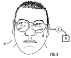
図3に示すように、前記成形キャビティは、眼鏡に似た装置30中に用意することができる。使用時に、前記装置は、前記キャビティが使用者32の眼の前面にあるよう、眼鏡のレンズがある位置と同じ位置に位置している。 As shown in FIG. 3, the molding cavity can be provided in an apparatus 30 similar to glasses. In use, the device is located at the same position as the eyeglass lens so that the cavity is in front of the user's 32 eye.
樹脂は、前記ポンプPにより前記キャビティに導入される。樹脂で満たされた前記キャ
ビティは、前記柔軟なシートにより可変焦点レンズとして機能することができる。そのようなレンズは、広く知られており、ここでは詳述しない。前記キャビティ中の樹脂の量を変えることにより、使用者は、視力の正確な矯正に必要な所望のパワーに達するまで、前記柔軟なシートの曲率を変えることで前記レンズのパワーを変えることができる。使用者は、正しい焦点に達するまで前記キャビティ中の樹脂を通して見ながらその樹脂の量を調整することができるので、該キャビティが使用者の眼の前面(眼鏡のレンズと同様)の位置にあるときには、この手順は単純になる。
Resin is introduced into the cavity by the pump P. The cavity filled with resin can function as a variable focus lens by the flexible sheet. Such lenses are widely known and will not be described in detail here. By changing the amount of resin in the cavity, the user can change the power of the lens by changing the curvature of the flexible sheet until the desired power required for accurate vision correction is reached. . The user can adjust the amount of resin while looking through the resin in the cavity until the correct focus is reached, so when the cavity is in front of the user's eye (similar to a lens in eyeglasses) This procedure will be simple.
前記キャビティ中の樹脂を、その後、熱にさらすか、あるいは紫外線に露光させることで硬化させることができ、それによってレンズができる。UV硬化性樹脂が用いられる場合、個々の樹脂にもよるが、周囲の太陽光中の紫外線量により充分に樹脂の硬化を生じさせることができる。代わりに、前記樹脂を電球等からの紫外線にさらしてもよい。 The resin in the cavity can then be cured by exposure to heat or exposure to ultraviolet light, thereby forming a lens. When a UV curable resin is used, although depending on the individual resin, the resin can be sufficiently cured by the amount of ultraviolet rays in the surrounding sunlight. Alternatively, the resin may be exposed to ultraviolet light from a light bulb or the like.
ひとたび樹脂が硬化したら、前記レンズを前記キャビティから取り除くことができ、標準的な眼鏡フレームなどに取り付けることができる。代わりに、図3に関して上述したように、前記キャビティが眼鏡に似た装置中に用意されるときは、前記レンズを、該装置の中に留めることができる。その場合、前記装置を、眼鏡として用いることができる。 Once the resin is cured, the lens can be removed from the cavity and attached to a standard eyeglass frame or the like. Alternatively, as described above with respect to FIG. 3, when the cavity is provided in a device similar to eyeglasses, the lens can remain in the device. In that case, the device can be used as glasses.
用いる樹脂の種類により、その樹脂の未硬化状態と硬化状態とでの屈折率が異なる場合がある。そのような屈折率の変化に合わせるため、最終使用者の要請に従って樹脂の量を調整した後に、少量の樹脂を、前記キャビティに導入し、または該キャビティから取り除くことができる。正確な必要量は、前記キャビティ中の樹脂の量及び屈折率の変化に基づいて計算することができる。 Depending on the type of resin used, the refractive index of the uncured state and the cured state of the resin may differ. To accommodate such refractive index changes, a small amount of resin can be introduced into or removed from the cavity after adjusting the amount of resin according to the end user's request. The exact required amount can be calculated based on the amount of resin in the cavity and the change in refractive index.
前記樹脂と使用者の皮膚、特に目とのいかなる接触をも避けることは、もちろん重要である。前記樹脂は通常の使用の間前記成形型の中に留まるであろうから、このことは、通常は問題とならない。しかし、シートが前記環と接合する箇所で樹脂が漏れ、あるいは、(例えば、前記成形型に導入した樹脂が多すぎる場合、)使用中にシートが裂けもしくは破裂する可能性はある。このようなことが起こると、前記樹脂が使用者と接触することとなり、非常に望ましくない。 It is of course important to avoid any contact between the resin and the user's skin, especially the eyes. This is usually not a problem because the resin will remain in the mold during normal use. However, there is a possibility that the resin leaks at the place where the sheet joins the ring, or the sheet tears or ruptures during use (for example, when too much resin is introduced into the mold). If this happens, the resin will come into contact with the user, which is highly undesirable.
図4で示される実施態様は、このような問題の解決を意図するものである。
この実施態様では、使用者は、樹脂を含む成形型10を通して見ない。ここで、前記樹脂を含む成形型は、使用者の目から離れた若干の距離をおいたところに留まっている。その代わりに、使用者は、第2のキャビティ40を通して見る。ここで、この該第2のキャビテ
ィは、成形型10に接続している。前記第2のキャビティ40は、可変焦点レンズの形状であるという点で前記成形型と同様の方法で形成される。また、該第2のキャビティ中の液体の量を、(例えば、手動ポンプ42または注射器などを使って)視力矯正を提供するために調整することができる。
The embodiment shown in FIG. 4 is intended to solve such a problem.
In this embodiment, the user does not look through the
前記成形型10中の樹脂の量を前記第2のキャビティ中の液体の量に従って調整するよう、前記成形型10は、第2のキャビティ40の従属装置として作動する。言い換えると、焦点を変えるために前記第2のキャビティ42に液体を導入するとき、樹脂は、成形型10にも導入される。同様に、液体を第2のキャビティ42から除去するとき、樹脂は成形型10から除去される。このような態様は、前記第2のキャビティ中の液体の量を調整するために用いられる手動ポンプ42上にセンサーを設置し、これらのセンサーにより検出された情報を用いて成形型(手動ポンプ42を樹脂ポンプPと接続する点線によって、図4に概略図として
示してある)のためにポンプPを制御することによって達成することができる。
The
ひとたび前記第2のキャビティ中の液体の量が適当な矯正を提供するために調整されたら、前記成形型10を封じ、樹脂を硬化させて、レンズを製造することができる。(もちろん、上述のように、硬化の際の屈折率変化を補正するために、樹脂を前記成形型に導入または該成形型から除去することができる。)
使用者が通して見る、前記第2のキャビティに用いられる液体は、使用者の皮膚または目と接触したときに有害でない液体であるべきである。水を用いることができるし、一定の油を用いてもよい。前記樹脂と前記液体との屈折率の差を考慮に入れるために樹脂の量を調整することは、もちろん必要である。
Once the amount of liquid in the second cavity has been adjusted to provide adequate correction, the
The liquid used in the second cavity as seen through the user should be a liquid that is not harmful when in contact with the user's skin or eyes. Water can be used or a certain oil can be used. Of course, it is necessary to adjust the amount of resin to take into account the difference in refractive index between the resin and the liquid.
更なる変形をなし得ることは、いうまでもない。例えば、樹脂が使用者の皮膚または目と接触するリスクなく矯正眼鏡を製造できるよう、成形装置を、使用者の各目の前面に位置する2つのそのような第2のキャビティと2つの成形型(これも眼鏡の形状をしている)とを有する眼鏡の形状で用意することができるだろう。 Needless to say, further modifications can be made. For example, the molding apparatus can be equipped with two such second cavities and two molds located in front of each eye of the user so that the corrective glasses can be manufactured without the risk of the resin coming into contact with the user's skin or eyes. Could be prepared in the shape of glasses (which also has the shape of glasses).
Claims (8)
前記成形キャビティを透明な樹脂で充填し;
前記シートによって特徴付けられる前記レンズの形状が所望のパワーを提供するよう、前記キャビティ中の樹脂の量を調整して、前記柔軟なシートを変形させ;そして、
前記樹脂を硬化すること
を含み、
前記キャビティ中の樹脂の量を調整して前記柔軟なシートを変形させることが、
前記レンズの形状及びパワーを最終使用者の視力に合わせて適合させることができるよう、該レンズの該最終使用者が前記透明なシート及び前記樹脂を通して見ている間に行われる
ことを特徴とする、透明な樹脂から視力矯正用レンズを成形する方法。There is provided a molding cavity for molding a lens, wherein side surfaces of the molding cavity corresponding to the front and rear surfaces of the lens are formed by two transparent sheets, and at least one of the sheets is flexible. ;
Filling the molding cavity with a transparent resin;
Deforming the flexible sheet by adjusting the amount of resin in the cavity so that the shape of the lens characterized by the sheet provides the desired power; and
Curing the resin,
Adjusting the amount of resin in the cavity to deform the flexible sheet;
It is performed while the end user of the lens is looking through the transparent sheet and the resin so that the shape and power of the lens can be adapted to the eyesight of the end user. A method for molding a vision correction lens from a transparent resin.
前記成形キャビティを透明な樹脂で充填し;
前記シートによって特徴付けられる前記レンズの形状が所望のパワーを提供するよう、前記キャビティ中の樹脂の量を調整して、前記柔軟なシートを変形させ;そして、
前記樹脂を硬化すること
を含み、
第2のキャビティが用意されており、該第2のキャビティが、前記成形キャビティと同様のものであって且つ透明なシートから形成された前面および後面を有しており、該シートのうち少なくとも1つが柔軟であり、該第2のキャビティの前記シートの柔軟性が、前記成形キャビティの対応するシートの柔軟性と同等であり、かつ該キャビティが透明な液体で満たされており、
前記レンズの最終使用者が、前記第2のキャビティを通して見ており、前記成形キャビティのシートによって特徴付けられる前記レンズの形状が所望のパワーを提供するよう、該第2のキャビティ中の液体の量を調整することで前記成形キャビティの柔軟なシートが変形し;かつ、
前記成形キャビティ中の樹脂の量が、第2のキャビティ中の液体の量に対応して調節されることを特徴とする、
透明な樹脂から視力矯正用レンズを成形する方法。 There is provided a molding cavity for molding a lens, wherein side surfaces of the molding cavity corresponding to the front and rear surfaces of the lens are formed by two transparent sheets, and at least one of the sheets is flexible. ;
Filling the molding cavity with a transparent resin;
Deforming the flexible sheet by adjusting the amount of resin in the cavity so that the shape of the lens characterized by the sheet provides the desired power; and
Curing the resin
Including
A second cavity is provided, the second cavity being similar to the molding cavity and having a front surface and a rear surface formed from a transparent sheet, wherein at least one of the sheets One is flexible, the flexibility of the sheet of the second cavity is equivalent to the flexibility of the corresponding sheet of the molding cavity, and the cavity is filled with a transparent liquid,
The amount of liquid in the second cavity so that the end user of the lens is looking through the second cavity and the shape of the lens characterized by a sheet of the molding cavity provides the desired power Adjusting the deformation of the flexible sheet of the molding cavity ; and
The amount of resin in the molding cavity is adjusted corresponding to the amount of liquid in the second cavity ,
A method for molding a vision correction lens from a transparent resin .
Applications Claiming Priority (3)
| Application Number | Priority Date | Filing Date | Title |
|---|---|---|---|
| GB0512012A GB2427169B (en) | 2005-06-13 | 2005-06-13 | Moulding lenses |
| GB0512012.6 | 2005-06-13 | ||
| PCT/GB2006/002112 WO2006134328A1 (en) | 2005-06-13 | 2006-06-08 | Moulding lenses |
Publications (2)
| Publication Number | Publication Date |
|---|---|
| JP2008546559A JP2008546559A (en) | 2008-12-25 |
| JP5065263B2 true JP5065263B2 (en) | 2012-10-31 |
Family
ID=34855451
Family Applications (1)
| Application Number | Title | Priority Date | Filing Date |
|---|---|---|---|
| JP2008516396A Expired - Fee Related JP5065263B2 (en) | 2005-06-13 | 2006-06-08 | How to mold a lens |
Country Status (12)
| Country | Link |
|---|---|
| US (1) | US8398902B2 (en) |
| EP (1) | EP1893400B1 (en) |
| JP (1) | JP5065263B2 (en) |
| KR (1) | KR101107185B1 (en) |
| CN (1) | CN101272896B (en) |
| AP (1) | AP2007004285A0 (en) |
| AT (1) | ATE439230T1 (en) |
| BR (1) | BRPI0612035A2 (en) |
| CA (1) | CA2611833C (en) |
| DE (1) | DE602006008458D1 (en) |
| GB (1) | GB2427169B (en) |
| WO (1) | WO2006134328A1 (en) |
Families Citing this family (11)
| Publication number | Priority date | Publication date | Assignee | Title |
|---|---|---|---|---|
| FR2996161B1 (en) * | 2012-09-28 | 2014-10-31 | Essilor Int | METHOD FOR MANUFACTURING AN OPHTHALMIC LENS |
| DE102013222232B4 (en) | 2013-10-31 | 2021-01-28 | Carl Zeiss Vision International Gmbh | Manufacturing process for a spectacle lens |
| US9588315B1 (en) * | 2014-03-28 | 2017-03-07 | Daniel Ryan Turner | Method and apparatus for deployment of a communication line onto a surface such as a roadway or pathway |
| US11583389B2 (en) | 2019-04-05 | 2023-02-21 | Amo Groningen B.V. | Systems and methods for correcting photic phenomenon from an intraocular lens and using refractive index writing |
| US11564839B2 (en) | 2019-04-05 | 2023-01-31 | Amo Groningen B.V. | Systems and methods for vergence matching of an intraocular lens with refractive index writing |
| US11944574B2 (en) | 2019-04-05 | 2024-04-02 | Amo Groningen B.V. | Systems and methods for multiple layer intraocular lens and using refractive index writing |
| US11678975B2 (en) | 2019-04-05 | 2023-06-20 | Amo Groningen B.V. | Systems and methods for treating ocular disease with an intraocular lens and refractive index writing |
| US11529230B2 (en) | 2019-04-05 | 2022-12-20 | Amo Groningen B.V. | Systems and methods for correcting power of an intraocular lens using refractive index writing |
| US11583388B2 (en) | 2019-04-05 | 2023-02-21 | Amo Groningen B.V. | Systems and methods for spectacle independence using refractive index writing with an intraocular lens |
| KR102395511B1 (en) * | 2020-12-11 | 2022-05-06 | 한국기술교육대학교 산학협력단 | Glasses based on thermo-reactive polymer lens and manufacturing method thereof |
| KR102395513B1 (en) * | 2020-12-11 | 2022-05-06 | 한국기술교육대학교 산학협력단 | Glasses based on photocurable lens and manufacturing method thereof |
Family Cites Families (12)
| Publication number | Priority date | Publication date | Assignee | Title |
|---|---|---|---|---|
| US3454686A (en) * | 1964-10-29 | 1969-07-08 | Harry S Jones | Method of shaping an aspheric lens |
| US4208365A (en) * | 1978-12-20 | 1980-06-17 | National Patent Development Corporation | Method and apparatus for molding toric contact lenses |
| DE3117474A1 (en) * | 1981-05-02 | 1982-11-18 | Fa. Carl Zeiss, 7920 Heidenheim | METHOD AND DEVICE FOR PRODUCING MOLDED PARTS WITH ASPHAERIC SURFACES |
| JPS57207026A (en) * | 1981-06-17 | 1982-12-18 | Hitachi Ltd | Method of molding plastic lens |
| GB8601967D0 (en) * | 1986-01-28 | 1986-03-05 | Coopervision Optics | Manufacturing contact lenses |
| JPH0755227B2 (en) * | 1990-03-30 | 1995-06-14 | ホーヤ株式会社 | Mold for molding intraocular lens precursor and method for manufacturing intraocular lens |
| JPH04284208A (en) * | 1991-03-14 | 1992-10-08 | Janome Sewing Mach Co Ltd | Manufacture of plastic lens |
| JP2662593B2 (en) | 1991-09-30 | 1997-10-15 | 名古屋大学長 | Variable focus lens and its focus control device |
| JPH112701A (en) | 1997-06-12 | 1999-01-06 | Kuniyasu Sowa | Diopter adjustment spectacles |
| MXPA01000792A (en) | 1998-07-24 | 2002-04-08 | Optical Molding Systems Inc | Method and compositions for manufacturing coated photochromatic articles. |
| US6830712B1 (en) * | 2000-08-28 | 2004-12-14 | Johnson & Johnson Vision Care, Inc. | Deformable molds and methods for their use in the manufacture of ophthalmic lenses |
| JP4284208B2 (en) * | 2004-02-23 | 2009-06-24 | パナソニック株式会社 | Tilt-type camera device |
-
2005
- 2005-06-13 GB GB0512012A patent/GB2427169B/en active Active
-
2006
- 2006-06-08 CA CA2611833A patent/CA2611833C/en not_active Expired - Fee Related
- 2006-06-08 AT AT06744163T patent/ATE439230T1/en not_active IP Right Cessation
- 2006-06-08 JP JP2008516396A patent/JP5065263B2/en not_active Expired - Fee Related
- 2006-06-08 AP AP2007004285A patent/AP2007004285A0/en unknown
- 2006-06-08 DE DE602006008458T patent/DE602006008458D1/en active Active
- 2006-06-08 EP EP06744163A patent/EP1893400B1/en not_active Not-in-force
- 2006-06-08 US US11/922,146 patent/US8398902B2/en not_active Expired - Fee Related
- 2006-06-08 WO PCT/GB2006/002112 patent/WO2006134328A1/en active Application Filing
- 2006-06-08 KR KR1020087000298A patent/KR101107185B1/en not_active IP Right Cessation
- 2006-06-08 BR BRPI0612035-0A patent/BRPI0612035A2/en not_active IP Right Cessation
- 2006-06-08 CN CN2006800210361A patent/CN101272896B/en not_active Expired - Fee Related
Also Published As
| Publication number | Publication date |
|---|---|
| AP2007004285A0 (en) | 2007-12-31 |
| EP1893400B1 (en) | 2009-08-12 |
| KR20080045670A (en) | 2008-05-23 |
| US20110018150A1 (en) | 2011-01-27 |
| ATE439230T1 (en) | 2009-08-15 |
| CN101272896A (en) | 2008-09-24 |
| CA2611833A1 (en) | 2006-12-21 |
| BRPI0612035A2 (en) | 2012-09-25 |
| GB0512012D0 (en) | 2005-07-20 |
| DE602006008458D1 (en) | 2009-09-24 |
| CN101272896B (en) | 2010-06-16 |
| WO2006134328A1 (en) | 2006-12-21 |
| EP1893400A1 (en) | 2008-03-05 |
| GB2427169A (en) | 2006-12-20 |
| JP2008546559A (en) | 2008-12-25 |
| CA2611833C (en) | 2013-03-19 |
| US8398902B2 (en) | 2013-03-19 |
| KR101107185B1 (en) | 2012-01-25 |
| GB2427169B (en) | 2010-10-06 |
Similar Documents
| Publication | Publication Date | Title |
|---|---|---|
| JP5065263B2 (en) | How to mold a lens | |
| EP2603823B1 (en) | Fluid-filled lenses and their ophthalmic applications | |
| TWI587022B (en) | Toric contact lens and method for making the same | |
| EP0610310B1 (en) | Method for manufacturing lenses using thin coatings | |
| CN105142886B (en) | The method of intraocular lens of the manufacture with embedded mask | |
| MX2014014478A (en) | Method for manufacturing a spectacle lens and spectacle lens. | |
| MX2012010869A (en) | Dynamic lens. | |
| CN102640038A (en) | Ophthalmic lenses for prevention of myopia progression | |
| JP2013507667A (en) | Non-round fluid-filled lens optics | |
| KR20230004522A (en) | ophthalmic lens shaping | |
| JP2010529491A (en) | Lens design to treat eye strain caused by visual impairment | |
| US20030090622A1 (en) | Spectacle lens of glass-resin lamination and production of the same | |
| EP1918760A1 (en) | Opthalmic lens, spectacles comprising ophthalmic lenses, apparatus for manufacturing an ophthalmic lens, method for manufacturing an opthalmic lens and a store comprising an apparatus for in store manufacturing of an ophthalmic lens | |
| US20220413321A1 (en) | Tuneable Ophthalmic Lens | |
| KR100638362B1 (en) | Contact lens and manufacturing method for the same and mold for manufacturing the same | |
| JP6899399B2 (en) | Plastic lenses for uncorrected eyeglasses | |
| WO2015107362A1 (en) | Method of making a flexible membrane and mold therefor, membrane and variable focus lens | |
| US20130235334A1 (en) | Ophthalmic lens forming optic | |
| KR20220166309A (en) | Shaping an ophthalmic lens | |
| JP2008185695A (en) | Far and near bifocal lens |
Legal Events
| Date | Code | Title | Description |
|---|---|---|---|
| A621 | Written request for application examination |
Free format text: JAPANESE INTERMEDIATE CODE: A621 Effective date: 20090316 |
|
| A977 | Report on retrieval |
Free format text: JAPANESE INTERMEDIATE CODE: A971007 Effective date: 20110531 |
|
| A131 | Notification of reasons for refusal |
Free format text: JAPANESE INTERMEDIATE CODE: A131 Effective date: 20110607 |
|
| A601 | Written request for extension of time |
Free format text: JAPANESE INTERMEDIATE CODE: A601 Effective date: 20110901 |
|
| A602 | Written permission of extension of time |
Free format text: JAPANESE INTERMEDIATE CODE: A602 Effective date: 20110908 |
|
| A521 | Request for written amendment filed |
Free format text: JAPANESE INTERMEDIATE CODE: A523 Effective date: 20111207 |
|
| A131 | Notification of reasons for refusal |
Free format text: JAPANESE INTERMEDIATE CODE: A131 Effective date: 20120110 |
|
| A601 | Written request for extension of time |
Free format text: JAPANESE INTERMEDIATE CODE: A601 Effective date: 20120406 |
|
| RD02 | Notification of acceptance of power of attorney |
Free format text: JAPANESE INTERMEDIATE CODE: A7422 Effective date: 20120406 |
|
| A521 | Request for written amendment filed |
Free format text: JAPANESE INTERMEDIATE CODE: A523 Effective date: 20120611 |
|
| A521 | Request for written amendment filed |
Free format text: JAPANESE INTERMEDIATE CODE: A523 Effective date: 20120528 |
|
| A602 | Written permission of extension of time |
Free format text: JAPANESE INTERMEDIATE CODE: A602 Effective date: 20120620 |
|
| TRDD | Decision of grant or rejection written | ||
| A01 | Written decision to grant a patent or to grant a registration (utility model) |
Free format text: JAPANESE INTERMEDIATE CODE: A01 Effective date: 20120710 |
|
| A01 | Written decision to grant a patent or to grant a registration (utility model) |
Free format text: JAPANESE INTERMEDIATE CODE: A01 |
|
| A61 | First payment of annual fees (during grant procedure) |
Free format text: JAPANESE INTERMEDIATE CODE: A61 Effective date: 20120809 |
|
| R150 | Certificate of patent or registration of utility model |
Free format text: JAPANESE INTERMEDIATE CODE: R150 |
|
| FPAY | Renewal fee payment (event date is renewal date of database) |
Free format text: PAYMENT UNTIL: 20150817 Year of fee payment: 3 |
|
| LAPS | Cancellation because of no payment of annual fees |