JP5064984B2 - Motorcycle steering assist system - Google Patents
Motorcycle steering assist system Download PDFInfo
- Publication number
- JP5064984B2 JP5064984B2 JP2007310104A JP2007310104A JP5064984B2 JP 5064984 B2 JP5064984 B2 JP 5064984B2 JP 2007310104 A JP2007310104 A JP 2007310104A JP 2007310104 A JP2007310104 A JP 2007310104A JP 5064984 B2 JP5064984 B2 JP 5064984B2
- Authority
- JP
- Japan
- Prior art keywords
- steering
- torque
- motorcycle
- acceleration
- target torque
- Prior art date
- Legal status (The legal status is an assumption and is not a legal conclusion. Google has not performed a legal analysis and makes no representation as to the accuracy of the status listed.)
- Expired - Fee Related
Links
Images


Classifications
-
- B—PERFORMING OPERATIONS; TRANSPORTING
- B62—LAND VEHICLES FOR TRAVELLING OTHERWISE THAN ON RAILS
- B62K—CYCLES; CYCLE FRAMES; CYCLE STEERING DEVICES; RIDER-OPERATED TERMINAL CONTROLS SPECIALLY ADAPTED FOR CYCLES; CYCLE AXLE SUSPENSIONS; CYCLE SIDE-CARS, FORECARS, OR THE LIKE
- B62K21/00—Steering devices
-
- B—PERFORMING OPERATIONS; TRANSPORTING
- B62—LAND VEHICLES FOR TRAVELLING OTHERWISE THAN ON RAILS
- B62J—CYCLE SADDLES OR SEATS; AUXILIARY DEVICES OR ACCESSORIES SPECIALLY ADAPTED TO CYCLES AND NOT OTHERWISE PROVIDED FOR, e.g. ARTICLE CARRIERS OR CYCLE PROTECTORS
- B62J45/00—Electrical equipment arrangements specially adapted for use as accessories on cycles, not otherwise provided for
- B62J45/40—Sensor arrangements; Mounting thereof
- B62J45/41—Sensor arrangements; Mounting thereof characterised by the type of sensor
- B62J45/415—Inclination sensors
- B62J45/4151—Inclination sensors for sensing lateral inclination of the cycle
-
- B—PERFORMING OPERATIONS; TRANSPORTING
- B62—LAND VEHICLES FOR TRAVELLING OTHERWISE THAN ON RAILS
- B62K—CYCLES; CYCLE FRAMES; CYCLE STEERING DEVICES; RIDER-OPERATED TERMINAL CONTROLS SPECIALLY ADAPTED FOR CYCLES; CYCLE AXLE SUSPENSIONS; CYCLE SIDE-CARS, FORECARS, OR THE LIKE
- B62K21/00—Steering devices
- B62K21/08—Steering dampers
Landscapes
- Engineering & Computer Science (AREA)
- Mechanical Engineering (AREA)
- Steering Control In Accordance With Driving Conditions (AREA)
Description
本発明は、自動二輪車のステアリング補助システムに関し、特に、ステアリングに対して操舵トルクを与えるアクチュエータを有するステアリング補助システムに関する。 The present invention relates to a steering assist system for a motorcycle, and more particularly to a steering assist system having an actuator that applies a steering torque to a steering.
自動二輪車の走行安定性能を一層向上させるために様々な制御技術の開発がなされている。走行安定性能の向上のためには、ステアリングダンパーを設けることが行われているが、例えば、特許文献1には、アクチュエータを設けてステアリング(後輪)をアクティブ制御することが提案されている。
Various control techniques have been developed to further improve the running stability of motorcycles. In order to improve the running stability performance, a steering damper is provided. For example,
特許文献1では、車速及びロールレートに応じて後輪の目標操舵角及び遅れ操舵角を決定し、操舵している。
In
ところで、自動二輪車は、四輪車と比較するとどうしても路面の凹凸や横風等による外乱を受けやすく、これらの外乱による操舵振れを低減することが望まれる。 By the way, compared with a four-wheeled vehicle, a motorcycle is inevitably subject to disturbances due to road surface irregularities, crosswinds, and the like, and it is desired to reduce steering shake due to these disturbances.
特許文献1記載の例では、基本的には操舵角の位置制御を行っているので、後輪に適用することは可能であっても、運転者が直接の操作をする前輪に適用することは実質上困難である。
In the example described in
また、特許文献1の例では、基本的にはレーンチェンジや旋回時の性能を向上させるものであって、外乱による操舵振れを低減することは考慮されていない。
Further, in the example of
本発明はこのような課題を考慮してなされたものであり、路面外乱や横風外乱による車体の横揺れ、操舵振れを更に低減させる自動二輪車のステアリング補助システムを提供することを目的とする。 The present invention has been made in consideration of such problems, and an object of the present invention is to provide a steering assist system for a motorcycle that further reduces rolling of the vehicle body due to road surface disturbance and side wind disturbance and steering vibration.
本発明に係る自動二輪車のステアリング補助システムは、以下の特徴を有する。 The steering assist system for a motorcycle according to the present invention has the following characteristics.
第1の特徴; 自動二輪車(11)のステアリング(18)に対して操舵トルクを与えるアクチュエータ(170)と、前記自動二輪車(11)の状態に基づいて前記ステアリング(18)の目標トルクを求める目標トルク算出部(200)と、操舵トルクを検出するトルク検出手段(46)と、前記目標トルク算出部(200)から得られる目標トルクと前記トルク検出手段(46)から得られる操舵トルクとの偏差に基づいて前記アクチュエータ(170)を駆動するトルク制御部(202)と、前記ステアリング(18)の操舵角に関する状態を検出する操舵角状態検出手段と、前記自動二輪車(11)の車幅方向の加速度を検出する加速度検出手段(62)とを有し、前記操舵角状態検出手段から得られる情報は操舵角加速度であり、前記車幅方向の加速度が所定値以上で、且つ前記操舵角加速度が所定値以上であるときに前記アクチュエータ(170)を駆動して前記ステアリング(18)に操舵トルクを与えることを特徴とする。 First feature: an actuator (170) that applies a steering torque to the steering (18) of the motorcycle (11), and a target for obtaining a target torque of the steering (18) based on the state of the motorcycle (11) Deviation between torque calculation unit (200), torque detection means (46) for detecting steering torque, and target torque obtained from target torque calculation unit (200) and steering torque obtained from torque detection means (46) Based on the torque control unit (202) for driving the actuator (170), steering angle state detecting means for detecting a state relating to the steering angle of the steering (18), and the vehicle width direction of the motorcycle (11). acceleration possess an acceleration detecting means for detecting (62) the information obtained from the steering angle condition detecting means is a steering angular acceleration, When the acceleration in the vehicle width direction is a predetermined value or more and the steering angular acceleration is a predetermined value or more, the actuator (170) is driven to give a steering torque to the steering (18) .
このように、目標トルクと実際の操舵トルクとの偏差に基づいてトルクの制御を行うことにより、路面外乱や横風外乱による車体の横揺れ、操舵振れを更に低減させることができる。また、運転者の操作に対する影響が少なくなり、通常走行時に運転者による操作が優先された自然な操作性が得られる。 Thus, by controlling the torque based on the deviation between the target torque and the actual steering torque, it is possible to further reduce the rolling of the vehicle body and the steering shake due to the road surface disturbance and the side wind disturbance. In addition, the influence on the driver's operation is reduced, and natural operability in which the operation by the driver is prioritized during normal driving is obtained.
第2の特徴; 前記自動二輪車(11)の車速を検出する車速検出手段(44)を有し、前記目標トルク算出部(200)は、前記操舵角状態検出手段から得られる情報、前記加速度検出手段(62)から得られる車幅方向の加速度及び前記車速検出手段(44)から得られる車速に基づいて、前記目標トルクを求めることを特徴とする。このような操舵角の情報、車幅方向の加速度及び車速に基づいてより適切な目標トルクが得られ、操舵振れを一層低減させることができる。 Second feature; pre SL has a vehicle speed detecting means (44) for detecting a vehicle speed of the motorcycle (11), the target torque calculating section (200), information obtained from the steering angle state detecting means, the acceleration The target torque is obtained on the basis of the acceleration in the vehicle width direction obtained from the detecting means (62) and the vehicle speed obtained from the vehicle speed detecting means (44). A more appropriate target torque can be obtained based on such information on the steering angle, the acceleration in the vehicle width direction, and the vehicle speed, and the steering shake can be further reduced.
第3の特徴; 前記目標トルク算出部(200)は、前記操舵トルクに対する前記車幅方向の加速度及び(又は)操舵角加速度を表す車体挙動伝達関数を用い、逆演算により前記目標トルクを求めることを特徴とする。このような車体挙動伝達関数を用いることにより、目標トルクを適切且つ簡便に求めることができる。 Third feature: The target torque calculation unit (200) obtains the target torque by inverse calculation using a vehicle body behavior transfer function representing acceleration in the vehicle width direction and / or steering angular acceleration with respect to the steering torque. It is characterized by. By using such a vehicle body behavior transfer function, the target torque can be obtained appropriately and simply.
本発明に係るステアリング補助システムによれば、目標トルクと実際の操舵トルクとの偏差に基づいてトルクの制御を行うことにより、路面外乱や横風外乱による車体の横揺れ、操舵振れを更に低減させることができる。 According to the steering assist system of the present invention, by controlling the torque based on the deviation between the target torque and the actual steering torque, the vehicle body roll due to road surface disturbance and side wind disturbance, and steering shake can be further reduced. Can do.
以下、本発明に係るステアリング補助システムについて実施の形態を挙げ、添付の図1〜図9を参照しながら説明する。本実施の形態に係るステアリング補助システム10は、自動二輪車11に搭載される。先ず、自動二輪車11について説明する。
DESCRIPTION OF EMBODIMENTS Hereinafter, a steering assist system according to the present invention will be described with reference to FIGS. A
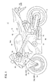
本実施の形態では、図1に示すように、フルカウリング型の自動二輪車11を例示して説明するが、本発明はこれに限られるものではなく、他の種別の自動二輪車(例えば、スクータ)にも適用可能である。なお、この自動二輪車11において、車体の左右に1つずつ対称的に設けられる機構乃至構成要素については、左側の参照符号に「L」を付し、右側の参照符号に「R」を付すものとする。また、以下の説明では、「右」は、自動二輪車11の運転者から見て車体の右側をいい、「左」は、運転者から見て車体の左側をいう。
In the present embodiment, as shown in FIG. 1, a full
図1に示すように、自動二輪車11は、車体を構成するクレードル型の車体フレーム12と、操舵輪である前輪14と、駆動輪である後輪16と、前輪14を操舵するハンドル18と、運転者が着座するシート20とを有する。後輪16は、エンジン19からトランスミッション(図示せず)を介して駆動される。
As shown in FIG. 1, a
図1及び図2に示すように、車体前方部におけるハンドル18には、トップブリッジ52が連結されている。トップブリッジ52の左右両側にはフロントフォーク24L、24Rが連結され、該フロントフォーク24L、24Rは、ボトムブリッジ54を貫通して前輪14を回転自在に軸支する。ボトムブリッジ54の中央部には、複合センサ60が取り付けられている。複合センサ60の下面はブラケット61aを介して車体フレーム12に固定されている。複合センサ60の上面の回転盤66(図3参照)はブラケット61bを介してボトムブリッジ54に固定されている。
As shown in FIGS. 1 and 2, a
シート20に着座した運転者がハンドル18を左右に操舵すると、ヘッドパイプ22を中心軸として、ハンドル18、トップブリッジ52、フロントフォーク24L、24R、ボトムブリッジ54及び前輪14を左右に一体的に回動させることができる。これにより複合センサ60の上面の回転盤66はブラケット61bによって回転する。
When the driver seated on the
また、フロントフォーク24L、24Rには、前輪14を上方から覆うフロントフェンダ25が取り付けられている。この場合、図2からも明らかなように、ボトムブリッジ54の下部は他の部品が配置されてない空きスペースであり、複合センサ60の取り付けに適している。また、複合センサ60は、フロントフェンダ25により、下方からの水、泥、砂等の進入を防止することができる。
A
さらに、自動二輪車11におけるカウル38の前方側には、ウインカ50L、50Rが配置され、自動二輪車11の後部側にはウインカ37L、37Rがそれぞれ配置されている。シート20の下方には自動二輪車11の電気的な制御を行うコントローラ42が設けられている。エンジン19の近傍には、エンジン回転数及び変速比等から車速を検出する車速センサ(車速検出手段)44が設けられている。
Further,
ヘッドパイプ22には、ハンドル18の操舵トルクを検出する操舵トルクセンサ(トルク検出手段)46(図4参照)が設けられている。また、ボトムブリッジ54下端には、自動二輪車11の傾斜角(つまり、ロール角)を検出する傾斜角センサ(傾斜角検出手段)48が設けられている。操舵トルクや傾斜角を検出する手段はセンサに限らず、例えば所定のパラメータから演算によってもとめてもよい。
The
ヘッドパイプ22の近傍でハンドル18と連動するポスト56(ボトムブリッジ54等でもよい)と、車体フレーム12との間には、ステアリング補助装置58が設けられている。エンジン19の近傍には油圧ポンプ(流体圧増減手段)59が設けられている。
A
図3に示すように、複合センサ60は、自動二輪車11のハンドル18(図1及び図2参照)の操舵角を検出する操舵角センサ(操舵角検出手段)64と、自動二輪車11のロール角(自動二輪車11の左右(車幅方向)の傾斜角度)に応じた重力加速度を検出する加速度センサ(車幅方向の加速度を検出する加速度検出手段)62と、操舵角センサ64及び加速度センサ62を一体収容するケース65と、上部の回転盤66を有する。加速度センサ62は半導体素子で構成されるものであり、廉価である。操舵角センサ64はポテンショメータであり、廉価である。
As shown in FIG. 3, the
ケース65の下面はブラケット61aに接続されており、回転盤66はブラケット61bに接続されている。ケース65内には隔壁119が設けられており、隔壁119の上面には基板90が設けられ、隔壁119の下の空間84には基準状態で水平な基板86が設けられている。基板90の上面には平面視で円弧状の抵抗体(例えば、コンダクティブプラスチック)が設けられている。回転盤66の下部には基板90の抵抗体に対して摺動する導電性ブラシ92が設けられており、抵抗体と導電性ブラシ92により操舵角センサ64を構成している。基板90と基板86はケーブルで接続されており、操舵角センサ64の信号は基板86を介してコントローラ42に供給される。操舵角センサ64に替えて例えばトルクセンサを用いてもよい。
The lower surface of the
基板86の底面には、加速度センサ62が配置されている。つまり、基板86及び加速度センサ62は、鉛直軸124に対して垂直で、略水平に配置され、且つ中心軸122に対して所定角度(中心軸122と鉛直軸124とのなす角度(キャスター角))だけ傾斜して空間84内に配置されている。また、前記基板86には、ケーブル112a〜112dが半田114a〜114dにより接続されている。複数のケーブル112a〜112dはゴム製のグロメット110を介して外部に引き出され、1本のハーネス113にまとめられてコントローラ42に接続されている。複合センサ60は外部からケース65内への水分、塵埃等の混入を防止するための複数のシールが設けられている。
An
図4に示すように、コントローラ42は、車速センサ44、操舵トルクセンサ46、傾斜角センサ48、操舵角センサ64及び加速度センサ62が接続されており、検出された車速V、操舵トルクT、傾斜角φ、操舵角θ及び加速度Gを示す信号が供給される。操舵トルクT、傾斜角φ及び操舵角θは、ハンドル18が基準状態(つまり、直進走行状態)であるときにそれぞれ0である。
As shown in FIG. 4, the
コントローラ42は、車速V、操舵トルクT、傾斜角φ、操舵角θ及び加速度Gに基づいて判断処理を行う判断部150と、外部のステアリング補助装置58及び油圧ポンプ59のモータ59aを制御するデバイス制御部154とを有する。コントローラ42は、主たる制御部としてのCPU(Central Processing Unit)と、記憶部としてのRAM(Random Access Memory)及びROM(Read Only Memory)及びドライバ等を有しており、CPUがプログラムを読み込み、記憶部等と協働しながらソフトウェア処理を実行することにより実現される。
The
図5に示すように、ステアリング補助装置58は、シリンダ(アクチュエータ)170と、電磁比例切換弁172とを有する。シリンダ170は、一方のシリンダチューブ173の端部がポスト56に対して回転自在に接続され、他方のロッド174の端部が車体フレーム12の一部に対して回転自在に接続されている。シリンダ170は、ステアリングに対して回転トルクを与えるように構成されている。ここでいう回転トルクとは、ステアリング操作を重くし、又は、軽くする方向のトルクを示し、さらに能動的な作用のみならず受動的に発生するトルクを含む。
As shown in FIG. 5, the steering assist
ロッド174にはピストン178が設けられており、シリンダチューブ173内を進退する。ピストン178には、ピストン178の両側の受圧室184a及び184bの間の連通手段(オリフィス等)は設けられていない。ロッド174は、シリンダチューブ173の端部のシール体180によって支持されており、該シール体180から外に出ている部分は蛇腹状のブーツ182で覆われている。シリンダ170の上部は、マニホールド形状になっており、電磁比例切換弁172が一体的に設けられている。
The
電磁比例切換弁172は、シリンダ170内におけるピストン178の両側の受圧室184a及び184bに対して、油圧ポンプ59から供給される圧力流体を切り換えて供給する。電磁比例切換弁172は、ボディ186と、該ボディ186内を進退動作するスプール188と、該スプール188を駆動するソレノイド190とを有し、ボディ186の入力ポート186pに供給される圧力流体の流路を選択的に切り換え、Aポート186a又はBポート186bのいずれか一方に連通させる。Aポート186a及びBポート186bのうち入力ポート186pに連通しない他方は、リターンポート186rに連通し、タンク192に連通する。Aポート186a及びBポート186bは、シリンダ170の受圧室184a及び184bに連通している。
The electromagnetic
ソレノイド190は、コントローラ42の作用下にスプール188を比例的に制御し、入力ポート186pから圧力流体を受圧室184a及び184bのいずれか一方に比例的に供給し、他方をタンク192に連通させることができる。ソレノイド190は、スプール188の駆動方向に合わせて、該スプール188の両端に設けられていてもよい。電磁比例切換弁172は、必ずしも比例弁でない切換弁でもよいが、比例式の電磁弁を用いることにより、様々な状況に対応できるため一層精度の高い制御が可能になる。
The
油圧ポンプ59はモータ59aによって回転し、タンク192内の液体(一般的には油)を吸い出して加圧し、電磁比例切換弁172に供給する。モータ59aはコントローラ42の作用下に速度及び(又は)トルク可変に制御され、油圧ポンプ59の回転数及び(又は)トルクが変化し、電磁比例切換弁172に対する加圧流体の圧力を調整することができる。電磁比例切換弁172に対する加圧流体の圧力を調整手段(流体圧増減手段)は、これに限らず、例えば、斜板式ポンプの斜板の傾斜角を調整してもよいし、圧力調整電磁比例弁を用いてもよい。油圧ポンプ59と電磁比例切換弁172との間には、圧力補償手段(例えばリリーフ弁)が設けられていてもよい。
The
次に、ステアリング補助システム10について説明する。
Next, the steering assist
図6に示すように、ステアリング補助システム10は、ステアリング補助装置58と、自動二輪車11の状態に基づいてステアリング(つまりハンドル18)の目標トルクTcを求める目標トルク算出部200と、目標トルクTcと操舵トルクセンサ46から得られる操舵トルクTとの偏差εに基づいてステアリング補助装置58を駆動するトルク制御部202とを有する。目標トルクTcは、車体挙動を安定化させるためのトルクである。
As shown in FIG. 6, the steering assist
さらに、ステアリング補助システム10は、操舵角θを検出する操舵角センサ64と、車幅方向の加速度Gを検出する加速度センサ62と車速Vを検出する車速センサ44とを有する。これらのセンサによって得られる自動二輪車11の状態量は、運転者の操作(ハンドル操作、アクセル操作、ブレーキ操作、体重移動等)に基づいて発生する状態量と、路面の凹凸や横風等による外乱Dに基づく状態量との合計量となっている。
Furthermore, the steering assist
目標トルク算出部200は、操舵角θ、車幅方向の加速度G及び車速Vに基づいて、目標トルクTcを求める。操舵角θについては、一階微分処理(操舵角状態検出手段)による角速度ω及び二回微分処理(操舵角状態検出手段)の角加速度aを利用可能である。なお、加速度G、操舵角θ、角速度ω及び角加速度aについては左右両方向に発生することからその符号は±の両方を取り得るが、理解を容易にするため、以下プラス側のみで説明をする。 The target torque calculation unit 200 calculates a target torque Tc based on the steering angle θ, the acceleration G in the vehicle width direction, and the vehicle speed V. Regarding the steering angle θ, the angular velocity ω by the first-order differentiation process (steering angle state detection means) and the angular acceleration a of the second differentiation process (steering angle state detection means) can be used. Note that the acceleration G, the steering angle θ, the angular velocity ω, and the angular acceleration a occur in both the left and right directions, so the sign can be both ±, but for the sake of easy understanding, only the plus side will be described below. .
トルク制御部202では、減算点204において操舵トルクT0と目標トルクTcとの偏差εを求め、補償部206において所定の制御補償(例えばPID補償)を行う。つまり、ステアリング補助システム10では、操舵トルクT0に基づくフィードバック制御がなされる。ここで、操舵トルクT0は、ハンドル18に実際に作用するトルクであり、ステアリング補助装置58によって作用するトルクT1と、運転者の操舵によって作用するトルクT2の合計トルクである。
The torque control unit 202 obtains a deviation ε between the steering torque T0 and the target torque Tc at the subtraction point 204, and the compensation unit 206 performs predetermined control compensation (for example, PID compensation). That is, the steering assist
トルク制御部202は、微小時間毎に繰り返し実行されるソフトウェア処理やアナログ回路等によって実現できる。目標トルク算出部200及びトルク制御部202は、前記の判断部150に設けられている。トルク制御部202によって求められた制御量は、デバイス制御部154におけるアンプ208で増幅されてステアリング補助装置58やモータ59aに供給される。また、デバイス制御部154では、供給される信号に基づき、電磁比例切換弁172の切り換え方向及び切り換え量を求め、制御をする。
The torque control unit 202 can be realized by software processing or an analog circuit that is repeatedly executed every minute time. The target torque calculation unit 200 and the torque control unit 202 are provided in the
次に、目標トルク算出部200における目標トルクTcの算出手順について説明する。図7におけるステップS1〜S6は所定の微小時間毎に繰り返し実行される。 Next, the calculation procedure of the target torque Tc in the target torque calculation unit 200 will be described. Steps S1 to S6 in FIG. 7 are repeatedly executed every predetermined minute time.
図7のステップS1において、車速センサ44、操舵角センサ64、加速度センサ62、及び操舵トルクセンサ46、及び傾斜角センサ48からその時点の車速V、操舵トルクT、傾斜角φ、操舵角θ及び車幅方向の加速度Gを得る。また、操舵角θを微分することにより角速度ω、角加速度aを求めておく。
In step S1 of FIG. 7, the
ステップS2において、トルク制御を実行するか否かの判定を行う。つまり、図8に示すように、車幅方向の加速度GがA1以上で操舵の角加速度aがA2以上である箇所を制御領域とし、ステアリング補助装置58のシリンダ170を駆動してハンドル18に操舵トルクを与えることになる。
In step S2, it is determined whether or not to execute torque control. That is, as shown in FIG. 8, a portion where the acceleration G in the vehicle width direction is A 1 or more and the angular acceleration a of steering is A 2 or more is set as a control region, and the
閾値としてのA1は、横風等の外乱がないと発生し得ない車幅方向の加速度に相当する値に設定され、閾値としてのA2は、路面の凹凸等の外乱がないと発生し得ないステアリングの加速度に相当する値に設定されている。すなわち、大きな外乱がない場合には、ステアリング補助システム10による補助制御は実質的には実行されないことになり、運転者の操作に対する影響が少なくなり、通常走行時に運転者による操作が優先された自然な操作性が得られる。なお、図8では2つのAND条件となっておいるが、いずれか一方の条件が成立したときにトルク制御を行うようにOR条件としてもよい。また、AND条件が成立する領域と、OR条件が成立する領域で操舵トルクを変更してもよい。
A 1 as a threshold value is set to a value corresponding to acceleration in the vehicle width direction that cannot be generated without disturbance such as cross wind, and A 2 as a threshold value can be generated without disturbance such as unevenness on the road surface. There is no value corresponding to the steering acceleration. That is, when there is no large disturbance, the assist control by the steering assist
閾値としてのA1及びA2は設計条件により調整可能であり、例えば、路面の凹凸等の外乱が発生した場合であっても、運転者の操作により容易に収束可能な程度の外乱であれば、トルク制御を働かせないように設定してもよい。 The thresholds A 1 and A 2 can be adjusted according to design conditions. For example, even if a disturbance such as road surface unevenness occurs, the disturbance can be easily converged by a driver's operation. The torque control may be set not to work.
トルク制御を実行する場合にはステップS3へ移り、実行しない場合には、ステップS6に移る。 If the torque control is to be executed, the process proceeds to step S3. If not, the process proceeds to step S6.
ステップS3において、操舵トルクT0に対する車幅方向の加速度Gを表す車体挙動伝達関数Z1を用い、逆演算(つまりZ1-1)により第1の目標トルクTc1を求める。車体挙動伝達関数Z1は、操舵トルクT0を入力として加速度Gを出力する関数であり、車速Vによる可変ゲインを有する。車体挙動伝達関数Z1における車速Vに基づく可変ゲインを図9におけるf1として表す。 In step S3, the first target torque Tc1 is obtained by inverse calculation (that is, Z1 −1 ) using the vehicle body behavior transfer function Z1 representing the acceleration G in the vehicle width direction with respect to the steering torque T0. The vehicle body behavior transfer function Z1 is a function that outputs the acceleration G with the steering torque T0 as an input, and has a variable gain according to the vehicle speed V. A variable gain based on the vehicle speed V in the vehicle body behavior transfer function Z1 is represented as f1 in FIG.
車体挙動伝達関数Z1は予め求められ、所定の記憶手段に記憶されているものであり、車幅方向の加速度Gと車体重量との積を外乱として、該外乱がステアリングに作用する力学系を示している。 The vehicle body behavior transfer function Z1 is obtained in advance and stored in a predetermined storage means, and indicates a dynamic system in which the disturbance acts on the steering by using the product of the acceleration G in the vehicle width direction and the vehicle body weight as a disturbance. ing.
ステップS4において、操舵トルクT0に対する車幅方向の角加速度aを表す車体挙動伝達関数Z2を用い、逆演算(つまりZ2-1)により第2の目標トルクTc2を求める。車体挙動伝達関数Z2は、操舵トルクT0を入力として角加速度aを出力する関数であり、車速Vによる可変ゲインを有する。車体挙動伝達関数Z2における車速Vに基づく可変ゲインを図9におけるf2として表す。 In step S4, the second target torque Tc2 is obtained by inverse calculation (that is, Z2 −1 ) using the vehicle body behavior transfer function Z2 representing the angular acceleration a in the vehicle width direction with respect to the steering torque T0. The vehicle body behavior transfer function Z2 is a function that outputs the angular acceleration a with the steering torque T0 as an input, and has a variable gain according to the vehicle speed V. The variable gain based on the vehicle speed V in the vehicle body behavior transfer function Z2 is represented as f2 in FIG.
車体挙動伝達関数Z2は予め求められ、所定の記憶手段に記憶されているものであり、角加速度aとステアリング慣性量との積を外乱として、該外乱がステアリングに作用する力学系を示している。 The vehicle body behavior transfer function Z2 is obtained in advance and stored in a predetermined storage means, and represents a dynamic system in which the disturbance acts on the steering with the product of the angular acceleration a and the steering inertia amount as a disturbance. .
例えば、ステップS3及びS4ともに予めその自動二輪車11にて操舵トルクと加速度Gの関係、操舵トルクと角加速度aの関係をテストによって求めておき、マップ化して記録しておくとよい。このように、ステップS3及びS4では、車体挙動伝達関数Z1、Z2を用いることにより、車体挙動を安定化させるための目標トルクTc1及びTc2を適切且つ簡便に求めることができる。
For example, in both steps S3 and S4, the relationship between the steering torque and the acceleration G and the relationship between the steering torque and the angular acceleration a may be obtained in advance by the
ステップS5において、2つの目標トルクTc1と目標トルクTc2を加算して最終的な目標トルクTcを得る。目標トルクTc1と目標トルクTc2のいずれか一方が十分に小さい場合、又は十分に小さいことが明らかである場合には、その算出を省略してもよい。この後、得られた目標トルクTcをトルク制御部202に供給する。 In step S5, the final target torque Tc is obtained by adding the two target torques Tc1 and Tc2. When either one of the target torque Tc1 and the target torque Tc2 is sufficiently small, or when it is clear that it is sufficiently small, the calculation may be omitted. Thereafter, the obtained target torque Tc is supplied to the torque control unit 202.
一方、ステップS6(ステップS2の判断が非成立のとき)において、シリンダ170によるダンパ効果及び通路抵抗によるダンパ効果を用い、コントローラ42からは油圧ポンプ59及び電磁比例切換弁172の制御をしない。
On the other hand, in step S6 (when the determination in step S2 is not established), the damper effect by the
ステップS5及びステップS6の後、図6に示す今回の処理を終了する。 After step S5 and step S6, the current process shown in FIG.
上述したように、本実施の形態に係るステアリング補助システム10によれば、目標トルクTcと実際の操舵トルクT0との偏差εに基づいてトルクの制御を行うことにより、路面外乱や横風外乱による車体の横揺れ、操舵振れを更に低減させることができる。
As described above, according to the steering assist
ステアリング補助システム10では、運転者の操舵によって作用するトルクT2を含めた実際の操舵トルクTによりフィードバック制御を行っているので、T2=Tであれば、ステアリング補助システム10として付加するトルクT1は0になり、無駄にトルクを作用させることがなく、必要十分なトルクだけが作用し、自然な操作感が得られる。もちろん、運転者が必要以上に大きいトルクT2を作用させている場合には、トルクT1はマイナスとなって、操舵トルクTを適正に保つことができる。
In the steering assist
また、このフィードバック制御では補償部206による適切な補償を行うことができ、ハンドル18の操舵振れを迅速且つ正確に低減、収束させることができる。
Further, in this feedback control, appropriate compensation by the compensation unit 206 can be performed, and the steering shake of the
さらに、操舵角θ、角速度ω、角加速度a、車幅方向の加速度G及び車速Vに基づいてより適切な目標トルクTcが得られ、操舵振れを一層低減させることができる。特に、従来技術に係る制御では、路面外乱や横風外乱を認識する手段や、該外乱に対する安定性確保のための手段はない。これに対して、本願ではこのような外乱を認識して、対応する制御を行い安定性を確保することができる。 Furthermore, a more appropriate target torque Tc can be obtained based on the steering angle θ, the angular velocity ω, the angular acceleration a, the acceleration G in the vehicle width direction, and the vehicle speed V, and the steering shake can be further reduced. In particular, in the control according to the prior art, there is no means for recognizing road surface disturbances or crosswind disturbances or means for ensuring stability against the disturbances. On the other hand, in the present application, it is possible to recognize such a disturbance and perform corresponding control to ensure stability.
また、図8に基づく制御領域に限りトルク制御を行うことから、旋回やレーンチェンジ時等の運転者の操作性を損なうことがない。 Further, since the torque control is performed only in the control region based on FIG. 8, the operability of the driver during turning or lane change is not impaired.
本発明に係るステアリング補助システムは、上述の実施の形態に限らず、本発明の要旨を逸脱することなく、種々の構成を採り得ることはもちろんである。 Needless to say, the steering assist system according to the present invention is not limited to the above-described embodiment, and can adopt various configurations without departing from the gist of the present invention.
10…ステアリング補助システム 11…自動二輪車
12…車体フレーム 18…ハンドル
42…コントローラ 44…車速センサ
46…操舵トルクセンサ 48…傾斜角センサ
58…ステアリング補助装置 59…油圧ポンプ
59a…モータ 60…複合センサ
62…加速度センサ 64…操舵角センサ
150…判断部 154…デバイス制御部
170…シリンダ 172…電磁比例切換弁
190…ソレノイド 200…目標トルク算出部
202…トルク制御部 204…減算点
206…補償部 208…アンプ
DESCRIPTION OF
Claims (3)
前記自動二輪車(11)の状態に基づいて前記ステアリング(18)の目標トルクを求める目標トルク算出部(200)と、
操舵トルクを検出するトルク検出手段(46)と、
前記目標トルク算出部(200)から得られる目標トルクと前記トルク検出手段(46)から得られる操舵トルクとの偏差に基づいて前記アクチュエータ(170)を駆動するトルク制御部(202)と、
前記ステアリング(18)の操舵角に関する状態を検出する操舵角状態検出手段と、
前記自動二輪車(11)の車幅方向の加速度を検出する加速度検出手段(62)と、
を有し、
前記操舵角状態検出手段から得られる情報は操舵角加速度であり、
前記車幅方向の加速度が所定値以上で、且つ前記操舵角加速度が所定値以上であるときに前記アクチュエータ(170)を駆動して前記ステアリング(18)に操舵トルクを与えることを特徴とする自動二輪車(11)のステアリング補助システム(10)。 An actuator (170) for applying a steering torque to the steering (18) of the motorcycle (11);
A target torque calculator (200) for determining a target torque of the steering (18) based on the state of the motorcycle (11);
Torque detection means (46) for detecting steering torque;
A torque controller (202) for driving the actuator (170) based on a deviation between a target torque obtained from the target torque calculator (200) and a steering torque obtained from the torque detector (46);
Steering angle state detecting means for detecting a state related to the steering angle of the steering (18);
Acceleration detecting means (62) for detecting acceleration in the vehicle width direction of the motorcycle (11);
I have a,
The information obtained from the steering angle state detecting means is steering angular acceleration,
An automatic driving system that applies the steering torque to the steering (18) by driving the actuator (170) when the acceleration in the vehicle width direction is a predetermined value or more and the steering angular acceleration is a predetermined value or more. A steering assist system (10) for a motorcycle (11).
前記自動二輪車(11)の車速を検出する車速検出手段(44)を有し、
前記目標トルク算出部(200)は、前記操舵角状態検出手段から得られる情報、前記加速度検出手段(62)から得られる車幅方向の加速度及び前記車速検出手段(44)から得られる車速に基づいて、前記目標トルクを求めることを特徴とする自動二輪車(11)のステアリング補助システム(10)。 In the steering assist system (10) of a motorcycle (11) according to claim 1 ,
Before SL has a vehicle speed detecting means for detecting (44) the speed of the motorcycle (11),
The target torque calculation unit (200) is based on the information obtained from the steering angle state detection means, the acceleration in the vehicle width direction obtained from the acceleration detection means (62), and the vehicle speed obtained from the vehicle speed detection means (44). Then, the steering assist system (10) of the motorcycle (11), wherein the target torque is obtained.
前記目標トルク算出部(200)は、前記操舵トルクに対する前記車幅方向の加速度及び(又は)操舵角加速度を表す車体挙動伝達関数を用い、逆演算により前記目標トルクを求めることを特徴とする自動二輪車(11)のステアリング補助システム(10)。 The steering assist system (10) for a motorcycle (11) according to claim 2 ,
The target torque calculation unit (200) uses the vehicle body behavior transfer function representing the acceleration in the vehicle width direction and / or the steering angular acceleration with respect to the steering torque, and calculates the target torque by reverse calculation. A steering assist system (10) for a motorcycle (11).
Priority Applications (3)
| Application Number | Priority Date | Filing Date | Title |
|---|---|---|---|
| JP2007310104A JP5064984B2 (en) | 2007-11-30 | 2007-11-30 | Motorcycle steering assist system |
| US12/289,395 US8606464B2 (en) | 2007-11-30 | 2008-10-27 | Steering assist system for motorcycle |
| DE102008059115A DE102008059115B4 (en) | 2007-11-30 | 2008-11-26 | Steering support system for a motorcycle |
Applications Claiming Priority (1)
| Application Number | Priority Date | Filing Date | Title |
|---|---|---|---|
| JP2007310104A JP5064984B2 (en) | 2007-11-30 | 2007-11-30 | Motorcycle steering assist system |
Publications (3)
| Publication Number | Publication Date |
|---|---|
| JP2009132271A JP2009132271A (en) | 2009-06-18 |
| JP2009132271A5 JP2009132271A5 (en) | 2010-08-19 |
| JP5064984B2 true JP5064984B2 (en) | 2012-10-31 |
Family
ID=40674597
Family Applications (1)
| Application Number | Title | Priority Date | Filing Date |
|---|---|---|---|
| JP2007310104A Expired - Fee Related JP5064984B2 (en) | 2007-11-30 | 2007-11-30 | Motorcycle steering assist system |
Country Status (3)
| Country | Link |
|---|---|
| US (1) | US8606464B2 (en) |
| JP (1) | JP5064984B2 (en) |
| DE (1) | DE102008059115B4 (en) |
Families Citing this family (37)
| Publication number | Priority date | Publication date | Assignee | Title |
|---|---|---|---|---|
| JP4936480B2 (en) * | 2009-06-24 | 2012-05-23 | タマデン工業株式会社 | Unmanned motorcycle with attitude control |
| JP5405969B2 (en) * | 2009-09-30 | 2014-02-05 | 本田技研工業株式会社 | Motorcycle steering device |
| WO2011054404A1 (en) * | 2009-11-09 | 2011-05-12 | öHLINS RACING AB | Steering damper and method for controlling steering damper |
| ES2884374T3 (en) * | 2009-12-25 | 2021-12-10 | Yamaha Motor Co Ltd | Method of determining conductor characteristics |
| JP5566750B2 (en) * | 2010-03-31 | 2014-08-06 | 本田技研工業株式会社 | Electric power steering device for saddle-ride type vehicles |
| JP5466126B2 (en) * | 2010-09-30 | 2014-04-09 | 本田技研工業株式会社 | Motorcycle attitude control device and motorcycle |
| DE102011009142B4 (en) | 2011-01-21 | 2017-03-16 | Edgar Uden | Stabilization system for two-wheelers |
| DE102011082413A1 (en) * | 2011-09-09 | 2013-03-14 | Robert Bosch Gmbh | Steering support system for a two-wheeler and steering for such a steering assistance system |
| JP5852471B2 (en) * | 2012-02-28 | 2016-02-03 | 株式会社豊田中央研究所 | Vehicle control device, steering simulation device, and program |
| JP5913766B2 (en) * | 2012-04-01 | 2016-04-27 | タマデン工業株式会社 | Unmanned motorcycle with attitude control |
| DE102012211963A1 (en) * | 2012-07-10 | 2014-01-30 | Robert Bosch Gmbh | Method for stabilizing a two-wheeler when cornering |
| JP5892922B2 (en) * | 2012-12-27 | 2016-03-23 | 本田技研工業株式会社 | Moving body |
| JP6117581B2 (en) * | 2013-03-25 | 2017-04-19 | 本田技研工業株式会社 | Moving body |
| JP6206819B2 (en) | 2015-09-28 | 2017-10-04 | 本田技研工業株式会社 | Saddle-type vehicle steering device |
| JP6222707B2 (en) * | 2015-09-28 | 2017-11-01 | 本田技研工業株式会社 | Saddle-type vehicle steering device |
| JP6187919B2 (en) | 2015-09-28 | 2017-08-30 | 本田技研工業株式会社 | Saddle-type vehicle steering device |
| JP6206818B2 (en) | 2015-09-28 | 2017-10-04 | 本田技研工業株式会社 | Saddle-type vehicle steering device |
| JP2017206168A (en) * | 2016-05-19 | 2017-11-24 | ヤマハ発動機株式会社 | Steering assist device, saddle-riding type vehicle, and steering assist method |
| JP2017206170A (en) * | 2016-05-19 | 2017-11-24 | ヤマハ発動機株式会社 | Rotation assist device, saddle-riding type vehicle, and rotation assist method |
| JP2017206169A (en) * | 2016-05-19 | 2017-11-24 | ヤマハ発動機株式会社 | Steering assist device, saddle-riding type vehicle, and steering assist method |
| JP6605133B2 (en) * | 2016-05-19 | 2019-11-13 | ヤマハ発動機株式会社 | Saddle-type vehicle having a bar handle |
| US10953890B2 (en) | 2016-10-19 | 2021-03-23 | Kawasaki Jukogyo Kabushiki Kaisha | Steering torque estimating device |
| US9932064B1 (en) * | 2016-12-21 | 2018-04-03 | Royce Merrell Dyar | Power steering system |
| DE102017200693A1 (en) | 2017-01-18 | 2018-07-19 | Bayerische Motoren Werke Aktiengesellschaft | Steering engagement device for a motorized two-wheeler |
| JP6745975B2 (en) * | 2017-03-22 | 2020-08-26 | 本田技研工業株式会社 | Steering damper |
| DE102017221642A1 (en) | 2017-12-01 | 2019-06-06 | Continental Automotive Gmbh | Apparatus for operating a motorcycle, system and method for operating a motorcycle |
| MX2020007563A (en) * | 2018-01-17 | 2020-09-03 | Tvs Motor Co Ltd | A motor vehicle and a front structure thereof. |
| US20210221368A1 (en) * | 2018-06-13 | 2021-07-22 | Ride Vision Ltd. | A rider assistance system and method |
| DE102018213298A1 (en) * | 2018-08-08 | 2020-02-13 | Robert Bosch Gmbh | Motorcycle and method and control device for controlling an active steering control system of a motorcycle |
| EP3828069B1 (en) | 2018-08-30 | 2024-03-13 | Yamaha Hatsudoki Kabushiki Kaisha | Attitude control actuator unit and leaning vehicle |
| JP7183280B2 (en) * | 2018-08-30 | 2022-12-05 | ヤマハ発動機株式会社 | STEERING ACTUATOR CONTROL DEVICE FOR LEAN VEHICLE AND LEAN VEHICLE |
| US11027786B2 (en) | 2018-11-20 | 2021-06-08 | Harley-Davidson Motor Company Group, LLC | Gyroscopic rider assist device |
| JP7261895B2 (en) * | 2019-09-27 | 2023-04-20 | 本田技研工業株式会社 | Straddle-type vehicle and control device |
| US20220340203A1 (en) * | 2019-09-30 | 2022-10-27 | Honda Motor Co., Ltd. | Steering assistance device for saddle type vehicle |
| JP6967092B2 (en) * | 2020-01-16 | 2021-11-17 | 本田技研工業株式会社 | Motorcycle |
| US11718360B1 (en) * | 2020-06-04 | 2023-08-08 | Daniel J. McAllister | Bicycle steering angle sensor assembly and mounting system for a bicycle steering angle sensor |
| WO2022141892A1 (en) * | 2020-12-31 | 2022-07-07 | 苏州大宏越科技有限公司 | Method for using electric vehicle assisted driving system |
Family Cites Families (10)
| Publication number | Priority date | Publication date | Assignee | Title |
|---|---|---|---|---|
| JP3061961B2 (en) * | 1992-09-16 | 2000-07-10 | 本田技研工業株式会社 | Vehicle steering system |
| JP3988182B2 (en) * | 2002-03-29 | 2007-10-10 | マツダ株式会社 | Electric power steering device for automobile |
| US7006901B2 (en) * | 2002-11-18 | 2006-02-28 | Wang Everett X | Computerized automated dynamic control system for single-track vehicles |
| US6863150B1 (en) * | 2003-09-25 | 2005-03-08 | Mitsubishi Denki Kabushiki Kaisha | Electric power steering control apparatus |
| JP4349309B2 (en) * | 2004-09-27 | 2009-10-21 | 日産自動車株式会社 | Vehicle steering control device |
| JP4482442B2 (en) * | 2004-12-27 | 2010-06-16 | ヤマハ発動機株式会社 | vehicle |
| DE102005047144A1 (en) | 2005-09-30 | 2007-04-05 | Bayerische Motoren Werke Ag | System for removing natural oscillations of front wheel guidance in single-lane motor vehicle, has actuator formed for automatic contact in vehicle control so that guidance moment is generated for reduction of natural oscillation |
| JP2007125917A (en) | 2005-11-01 | 2007-05-24 | Yamaha Motor Co Ltd | Control system, and motorcycle equipped with that |
| DE102006024327A1 (en) | 2006-05-24 | 2007-11-29 | Bayerische Motoren Werke Ag | motorcycle |
| JP5124832B2 (en) * | 2008-01-31 | 2013-01-23 | 本田技研工業株式会社 | Vehicle steering device |
-
2007
- 2007-11-30 JP JP2007310104A patent/JP5064984B2/en not_active Expired - Fee Related
-
2008
- 2008-10-27 US US12/289,395 patent/US8606464B2/en active Active
- 2008-11-26 DE DE102008059115A patent/DE102008059115B4/en not_active Expired - Fee Related
Also Published As
| Publication number | Publication date |
|---|---|
| US20090139793A1 (en) | 2009-06-04 |
| JP2009132271A (en) | 2009-06-18 |
| DE102008059115A1 (en) | 2009-07-09 |
| DE102008059115B4 (en) | 2011-07-21 |
| US8606464B2 (en) | 2013-12-10 |
Similar Documents
| Publication | Publication Date | Title |
|---|---|---|
| JP5064984B2 (en) | Motorcycle steering assist system | |
| JP4997047B2 (en) | Steering assist system and steering assist method | |
| JP5093552B2 (en) | Vehicle steering system | |
| JP2538939B2 (en) | Vehicle steering angle control device | |
| EP3508409B1 (en) | Motor vehicle | |
| JP5191057B2 (en) | Steering damper device | |
| CN110650887B (en) | Vehicle with a steering wheel | |
| JP2007125917A (en) | Control system, and motorcycle equipped with that | |
| JP5998630B2 (en) | Power steering system, vehicle equipped with the same, and control method thereof | |
| JP6948157B2 (en) | Vehicle control device | |
| JP2022523577A (en) | Vehicle stabilization system and how it operates | |
| JP5380860B2 (en) | Lane maintenance support device and lane maintenance support method | |
| US6705631B2 (en) | Steering damper system for vehicles | |
| JP4997041B2 (en) | Disturbance behavior detection system for motorcycles | |
| JP4647916B2 (en) | Motorcycle with auxiliary wheels | |
| KR20170075601A (en) | Apparatus and method for controlling active front steering system | |
| JP2023534311A (en) | Balancing assistance system for saddle-type automobiles | |
| JP4186614B2 (en) | Steering control device | |
| JP2017094993A (en) | Tire force control device and saddle-riding type vehicle mounted with tire force control device | |
| JP2717676B2 (en) | Rear wheel steering control device for vehicle | |
| JP3703321B2 (en) | Power steering device | |
| JP4114340B2 (en) | Electric power steering device for automobile | |
| WO2023144922A1 (en) | Tilting vehicle | |
| JP7413572B2 (en) | vehicle | |
| EP4255797A2 (en) | A balancing system for a vehicle |
Legal Events
| Date | Code | Title | Description |
|---|---|---|---|
| A521 | Request for written amendment filed |
Free format text: JAPANESE INTERMEDIATE CODE: A523 Effective date: 20100702 |
|
| A621 | Written request for application examination |
Free format text: JAPANESE INTERMEDIATE CODE: A621 Effective date: 20100702 |
|
| A977 | Report on retrieval |
Free format text: JAPANESE INTERMEDIATE CODE: A971007 Effective date: 20111227 |
|
| A131 | Notification of reasons for refusal |
Free format text: JAPANESE INTERMEDIATE CODE: A131 Effective date: 20120110 |
|
| A521 | Request for written amendment filed |
Free format text: JAPANESE INTERMEDIATE CODE: A523 Effective date: 20120221 |
|
| TRDD | Decision of grant or rejection written | ||
| A01 | Written decision to grant a patent or to grant a registration (utility model) |
Free format text: JAPANESE INTERMEDIATE CODE: A01 Effective date: 20120731 |
|
| A01 | Written decision to grant a patent or to grant a registration (utility model) |
Free format text: JAPANESE INTERMEDIATE CODE: A01 |
|
| A61 | First payment of annual fees (during grant procedure) |
Free format text: JAPANESE INTERMEDIATE CODE: A61 Effective date: 20120809 |
|
| R150 | Certificate of patent or registration of utility model |
Ref document number: 5064984 Country of ref document: JP Free format text: JAPANESE INTERMEDIATE CODE: R150 Free format text: JAPANESE INTERMEDIATE CODE: R150 |
|
| FPAY | Renewal fee payment (event date is renewal date of database) |
Free format text: PAYMENT UNTIL: 20150817 Year of fee payment: 3 |
|
| R250 | Receipt of annual fees |
Free format text: JAPANESE INTERMEDIATE CODE: R250 |
|
| LAPS | Cancellation because of no payment of annual fees |