JP5064247B2 - Method and structure for reinforcing bridge - Google Patents

Method and structure for reinforcing bridge Download PDF

Info

Publication number
JP5064247B2
JP5064247B2 JP2008007879A JP2008007879A JP5064247B2 JP 5064247 B2 JP5064247 B2 JP 5064247B2 JP 2008007879 A JP2008007879 A JP 2008007879A JP 2008007879 A JP2008007879 A JP 2008007879A JP 5064247 B2 JP5064247 B2 JP 5064247B2
Authority
JP
Japan
Prior art keywords
bypass
bridge
girder
plate
reinforcing
Prior art date
Legal status (The legal status is an assumption and is not a legal conclusion. Google has not performed a legal analysis and makes no representation as to the accuracy of the status listed.)
Active
Application number
JP2008007879A
Other languages
Japanese (ja)
Other versions
JP2009167716A (en
Inventor
裕一 道菅
政直 鈴木
Current Assignee (The listed assignees may be inaccurate. Google has not performed a legal analysis and makes no representation or warranty as to the accuracy of the list.)
IHI Infrastructure Systems Co Ltd
Original Assignee
IHI Infrastructure Systems Co Ltd
Priority date (The priority date is an assumption and is not a legal conclusion. Google has not performed a legal analysis and makes no representation as to the accuracy of the date listed.)
Filing date
Publication date
Application filed by IHI Infrastructure Systems Co Ltd filed Critical IHI Infrastructure Systems Co Ltd
Priority to JP2008007879A priority Critical patent/JP5064247B2/en
Publication of JP2009167716A publication Critical patent/JP2009167716A/en
Application granted granted Critical
Publication of JP5064247B2 publication Critical patent/JP5064247B2/en
Active legal-status Critical Current
Anticipated expiration legal-status Critical

Links

Images

Description

本発明は、桁部材同士が添接板を介してボルト締結されて構成された既設橋梁の補強方法及び補強構造に関する。   The present invention relates to a reinforcing method and a reinforcing structure of an existing bridge configured by bolting girder members via bolts.

近年、既設の橋梁を現行の耐震基準に合わせるための補強工事が種々行われている。図6及び図7に示すように、トラス橋からなる橋梁1には、複数の鋼製の桁部材2で構成され、桁部材2同士が添接板3を介してボルト締結されて構成されたものがある。かかる橋梁1の添接板3長手方向の桁部材2同士の耐震強度を高めるべく添接部を補強する場合、現地で添接板3のボルト(図示せず)を取り外し、既設の添接板3を厚い添接板(図示せず)に交換することで行っていた。   In recent years, various reinforcement works have been performed to match existing bridges with current seismic standards. As shown in FIGS. 6 and 7, the bridge 1 made of a truss bridge is composed of a plurality of steel girder members 2, and the girder members 2 are bolted together via an attachment plate 3. There is something. In order to reinforce the connecting portion in order to increase the seismic strength between the longitudinal members 3 of the connecting plate 3 of the bridge 1, the bolt (not shown) of the connecting plate 3 is removed at the site, and the existing connecting plate 3 was replaced by a thick accessory plate (not shown).

特開2006−231338号公報JP 2006-231338 A 特開2003−328451号公報JP 2003-328451 A

しかしながら、添接板3を一旦取り外すこととなるため、桁部材2の四辺のそれぞれに多数のボルトで締結される添接板3を部分毎に交換する必要があり、効率が悪く、工程に問題があるという課題があった。   However, since the attachment plate 3 is once removed, it is necessary to replace the attachment plate 3 fastened with a large number of bolts to each of the four sides of the girder member 2 for each part, which is inefficient and causes problems in the process. There was a problem that there was.

そこで、本発明の目的は、上記課題を解決し、既設橋梁の添接部を効率よく補強できる橋梁の補強方法及び補強構造を提供することにある。   Accordingly, an object of the present invention is to solve the above-described problems and provide a bridge reinforcing method and a reinforcing structure that can efficiently reinforce the connecting portion of an existing bridge.

上記課題を解決するために本発明は、複数の鋼製の桁部材で構成され、桁部材同士が添接板を介してボルト締結されて構成された既設の橋梁の補強方法であって、上記添接板が取り付けられた桁部材の長手方向の両側に設けられる応力導入プレートと、その応力導入プレート同士を連結して応力を伝達するバイパスリブとでバイパス部材を構成し、そのバイパス部材で添接板を跨いで添接板の両側にバイパス部材をあてがうと共に応力導入プレートを桁部材にボルトで締結するものである。   In order to solve the above-mentioned problem, the present invention is a method for reinforcing an existing bridge, which is composed of a plurality of steel girder members, and each girder member is bolted via an attachment plate. A bypass member is constituted by a stress introduction plate provided on both sides in the longitudinal direction of the girder member to which the attachment plate is attached, and a bypass rib that connects the stress introduction plates to transmit stress, and the bypass member adds the bypass member. The bypass member is applied to both sides of the attachment plate across the contact plate, and the stress introduction plate is fastened to the girder member with bolts.

上記バイパスリブが、上記応力導入プレート間に複数掛け渡して設けられるとよい。   It is preferable that a plurality of the bypass ribs are provided between the stress introduction plates.

また、上記バイパスリブ間に上記ボルトの頭を収容する収容スペースが形成されるとよい。   An accommodation space for accommodating the head of the bolt may be formed between the bypass ribs.

上記複数のバイパスリブが、上記応力導入プレート間で座屈防止プレートを介して接続されて補強されるとよい。   The plurality of bypass ribs may be reinforced by being connected between the stress introduction plates via a buckling prevention plate.

上記座屈防止プレートに、ボルト締結用の工具を通すための作業用孔を形成するとよい。   A work hole for passing a bolt fastening tool may be formed in the buckling prevention plate.

また、上記添接板でボルト締結された桁部材の一方に、この桁部材に対して交差する交差部材が取り付けられた橋梁を補強すべく、上記バイパス部材のバイパスリブを分割し、これら分割バイパスリブに上記交差部材と接合する接合フランジを形成し、これら接合フランジ同士を交差部材を介して一体にボルト締結するとよい。   Further, the bypass rib of the bypass member is divided into one of the girder members bolted by the attachment plate, and the bypass rib of the bypass member is divided to reinforce the bridge attached to the girder member. A joining flange for joining the cross member to the rib may be formed, and the joint flanges may be bolted together via the cross member.

本発明によれば、既設橋梁の添接部を効率よく補強できる。   According to the present invention, it is possible to efficiently reinforce the connecting portion of the existing bridge.

本発明の好適実施の形態を添付図面を用いて説明する。   Preferred embodiments of the present invention will be described with reference to the accompanying drawings.

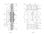
図7は補強すべき既設橋梁の要部側面図であり、図1は図7の部分A(縦桁)の添接部をバイパス部材で補強した状態の斜視図であり、図2(a)は図1に示すバイパス部材の側面図であり、図2(b)は図2(a)の正面図である。   FIG. 7 is a side view of an essential part of an existing bridge to be reinforced, and FIG. 1 is a perspective view showing a state where a connecting portion of a portion A (vertical girder) in FIG. 7 is reinforced with a bypass member. FIG. 2 is a side view of the bypass member shown in FIG. 1, and FIG. 2 (b) is a front view of FIG. 2 (a).

図6及び図7に示すように、補強すべき既存橋梁1は、複数の鋼製の縦、横、斜めの桁部材2で構成され、桁部材2同士が添接板3を介してボルト締結されて構成されたトラス橋からなる。桁部材2は、鋼板4で外周の4辺を構成した断面矩形状の箱断面構造に形成されている。また、桁部材2には、作業員が内部に入れるようにするためのマンホール(図示せず)が設けられており、桁部材2の内部でもボルト締結等の作業が行えるようになっている。   As shown in FIG. 6 and FIG. 7, the existing bridge 1 to be reinforced is composed of a plurality of steel vertical, horizontal and diagonal girder members 2, and the girder members 2 are fastened with bolts via an attachment plate 3. It consists of a truss bridge constructed. The girder member 2 is formed in a box cross-sectional structure having a rectangular cross-section in which four sides of the outer periphery are constituted by a steel plate 4. Further, the girder member 2 is provided with a manhole (not shown) for allowing an operator to enter the girder member 2, so that a bolt fastening operation can be performed inside the girder member 2.

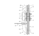
図1及び図2(a)、(b)に示すように、この橋梁1の添接板3長手方向の桁部材2同士の耐震強度を高める場合、添接部5の桁部材2に設けるためのバイパス部材6を作製する。   As shown in FIGS. 1 and 2 (a) and 2 (b), when the seismic strength of the girder members 2 in the longitudinal direction of the attachment plate 3 of the bridge 1 is increased, the girder member 2 of the attachment portion 5 is provided. The bypass member 6 is prepared.

バイパス部材6は、添接板3が取り付けられた桁部材2の長手方向の両側に設けられる一対の応力導入プレート7、7と、これら応力導入プレート7、7同士を連結して応力を伝達する複数のバイパスリブ8と、これらバイパスリブ8を補強すべく接続する座屈防止プレート9とを備えて構成される。   The bypass member 6 transmits a stress by connecting a pair of stress introduction plates 7 and 7 provided on both sides in the longitudinal direction of the girder member 2 to which the attachment plate 3 is attached, and connecting the stress introduction plates 7 and 7 together. A plurality of bypass ribs 8 and a buckling prevention plate 9 connected to reinforce these bypass ribs 8 are provided.

応力導入プレート7、7は、それぞれ矩形状に形成されており、ボルト10を挿通させるための孔11を複数有する。孔11の数は、桁部材2に作用する力をバイパス部材6にその許容応力まで入力できるボルト10の数と同じに設定される。   The stress introduction plates 7 and 7 are each formed in a rectangular shape and have a plurality of holes 11 through which the bolts 10 are inserted. The number of holes 11 is set to be the same as the number of bolts 10 that can input the force acting on the girder member 2 up to the allowable stress to the bypass member 6.

バイパスリブ8は、応力導入プレート7、7間の桁部材2側の端部に添接板3を回避するための切欠12を有してコ字状又はアーチ状に形成された板材からなり、一対の応力導入プレート7、7に対して直交して配置されると共に、両端を溶接にて一体に固定される。切欠12の大きさは、バイパスリブ8が添接板3に干渉せず、かつ、添接板3から大きく離れないように添接板3の板厚に応じて設定される。バイパス部材6と桁部材2が離れているとバイパス部材6に偏心曲げ等の不要な力が働くためである。また、複数のバイパスリブ8は、一対の応力導入プレート7、7の離間方向に沿って平行に配置される。バイパスリブ8間に形成される間隙のいずれかには、添接板3を留めるボルト13の頭14を収容する収容スペース15が形成される。収容スペース15は、いずれかのバイパスリブ8間の間隔をボルト13の頭14の直径よりも大きくすることで形成される。バイパスリブ8の板厚と枚数は、バイパス部材6に求められる許容応力に応じて決定される。   The bypass rib 8 is made of a plate material having a U-shape or an arch shape having a notch 12 for avoiding the attachment plate 3 at the end portion between the stress introduction plates 7 and 7 on the side of the girder member 2, While being disposed orthogonally to the pair of stress introduction plates 7, 7, both ends are fixed integrally by welding. The size of the notch 12 is set according to the thickness of the attachment plate 3 so that the bypass rib 8 does not interfere with the attachment plate 3 and is not greatly separated from the attachment plate 3. This is because if the bypass member 6 and the girder member 2 are separated, unnecessary force such as eccentric bending acts on the bypass member 6. The plurality of bypass ribs 8 are arranged in parallel along the direction in which the pair of stress introduction plates 7 and 7 are separated from each other. In any of the gaps formed between the bypass ribs 8, an accommodation space 15 for accommodating the head 14 of the bolt 13 that fastens the attachment plate 3 is formed. The accommodation space 15 is formed by making the interval between any of the bypass ribs 8 larger than the diameter of the head 14 of the bolt 13. The thickness and number of the bypass ribs 8 are determined according to the allowable stress required for the bypass member 6.

座屈防止プレート9は、応力導入プレート7、7と同等又は応力導入プレート7、7より小さな幅寸法に形成されており、切欠12とは反対側のバイパスリブ8に溶接にて一体に固定される。収容スペース15に臨む座屈防止プレート9には、電動レンチ等のボルト締結用の工具(図示せず)を通すための作業用孔16が形成されており、桁部材2からバイパス部材6を取り外さなくとも収容スペース15内のボルト13を増し締めする等のメンテナンスができるようになっている。   The buckling prevention plate 9 is formed to have a width that is equal to or smaller than the stress introduction plates 7 and 7 and is integrally fixed to the bypass rib 8 on the side opposite to the notch 12 by welding. The The buckling prevention plate 9 facing the accommodation space 15 is formed with a working hole 16 for passing a bolt fastening tool (not shown) such as an electric wrench, and the bypass member 6 is removed from the girder member 2. The maintenance such as retightening the bolts 13 in the accommodation space 15 can be performed at least.

バイパス部材6を作製したら、応力導入プレート7、7に形成された孔11のピッチに応じて添接板3両側の桁部材2にボルト孔(図示せず)を穿ち、バイパス部材6で添接板3を跨いで添接板3の両側にバイパス部材6をあてがうと共に、応力導入プレート7、7を桁部材2にボルト10で締結する。これにより、バイパス部材6は添接板3やボルト13に干渉することなく桁部材2に近接して取り付けられ添接部5が補強される。   After the bypass member 6 is produced, bolt holes (not shown) are drilled in the girder members 2 on both sides of the attachment plate 3 according to the pitch of the holes 11 formed in the stress introduction plates 7, 7, and the bypass member 6 is attached. The bypass member 6 is applied to both sides of the attachment plate 3 across the plate 3, and the stress introduction plates 7 and 7 are fastened to the girder member 2 with bolts 10. Thereby, the bypass member 6 is attached in the vicinity of the girder member 2 without interfering with the attachment plate 3 and the bolt 13, and the attachment portion 5 is reinforced.

このように、添接板3が取り付けられた桁部材2の長手方向の両側に設けられる応力導入プレート7、7と、その応力導入プレート7、7同士を連結して応力を伝達するバイパスリブ8とでバイパス部材6を構成し、そのバイパス部材6で添接板3を跨いで添接板3の両側にバイパス部材6をあてがうと共に応力導入プレート7、7を桁部材2にボルト10で締結して添接部5を補強するため、桁部材2から既設の添接板3や添接板3を留める多数のボルト13を取り外すことなく添接部5を補強することができ、効率よく作業できる。また、取り外したボルト13等の部品を管理する必要がなく、添接部5の強度が低下する瞬間もないため、安全に作業を行うことができる。   As described above, the stress introduction plates 7 and 7 provided on both sides in the longitudinal direction of the girder member 2 to which the attachment plate 3 is attached, and the bypass rib 8 that transmits the stress by connecting the stress introduction plates 7 and 7 to each other. The bypass member 6 is configured with the bypass member 6 across the attachment plate 3 and the bypass member 6 is applied to both sides of the attachment plate 3 and the stress introduction plates 7 and 7 are fastened to the girder member 2 with bolts 10. Since the attachment portion 5 is reinforced, the attachment portion 5 can be reinforced without removing the existing attachment plate 3 and the numerous bolts 13 that fasten the attachment plate 3 from the girder member 2, and work can be performed efficiently. . Further, it is not necessary to manage the removed bolts 13 and the like, and since there is no moment when the strength of the contact portion 5 is reduced, the work can be performed safely.

バイパスリブ8が、応力導入プレート7、7間に複数掛け渡して設けられるものとしたため、バイパスリブ8の枚数を変えることで強度の異なる複数種類のバイパス部材6を容易に作製でき、バイパス部材6を安価なものにできる。   Since a plurality of bypass ribs 8 are provided between the stress introduction plates 7 and 7, a plurality of types of bypass members 6 having different strengths can be easily manufactured by changing the number of bypass ribs 8. Can be made inexpensive.

バイパスリブ8間にボルト13の頭14を収容する収容スペース15が形成されるものとしたため、簡単な構造でボルト13を回避でき、バイパス部材6を安価なものにできる。   Since the accommodation space 15 for accommodating the head 14 of the bolt 13 is formed between the bypass ribs 8, the bolt 13 can be avoided with a simple structure, and the bypass member 6 can be made inexpensive.

複数のバイパスリブ8が、応力導入プレート7、7間で座屈防止プレート9を介して接続されて補強されるものとしたため、簡単な構造でバイパスリブ8を強固に補強することができる。   Since the plurality of bypass ribs 8 are connected and reinforced between the stress introduction plates 7 and 7 via the buckling prevention plate 9, the bypass ribs 8 can be firmly reinforced with a simple structure.

座屈防止プレート9に、ボルト締結用の工具を通すための作業用孔16を形成したため、バイパス部材6が桁部材2に取り付けられた状態のままでも添接板3を留めるボルト13のメンテナンスを行うことができる。   Since the working hole 16 for passing the bolt fastening tool is formed in the buckling prevention plate 9, the maintenance of the bolt 13 for fastening the attachment plate 3 is maintained even when the bypass member 6 is attached to the girder member 2. It can be carried out.

なお、応力導入プレート7、7は矩形状に形成されるものとしたが、これに限るものではなく、桁部材2の幅形状に応じた形状に形成するとよい。   In addition, although the stress introduction plates 7 and 7 shall be formed in the rectangular shape, it is not restricted to this, It is good to form in the shape according to the width | variety shape of the girder member 2. FIG.

次に他の実施の形態について述べる。   Next, another embodiment will be described.

図3及び図4に示すように、突き合わせて配置されると共に添接板3でボルト締結される2つの桁部材2の一方に、この桁部材2に対して交差する桁部材2aが取り付けられ、上述のバイパス部材6では交差する桁部材2aの鋼板4かならなる交差部材20が邪魔となって桁部材2にバイパス部材6を取り付けられない場合、まず、上述のバイパス部材6のバイパスリブ8を応力導入プレート7、7間で分割して一対の分割バイパス部材21、22を形成し、これら分割バイパス部材21、22の分割バイパスリブ23、24の分割端に交差部材20と接合する接合フランジ25を形成したバイパス部材26を作製する。桁部材2a内に配置される下側の分割バイパス部材22は、桁部材2a内での取り扱いを容易にするために幅方向に分割されてなる。   As shown in FIGS. 3 and 4, a girder member 2 a that intersects the girder member 2 is attached to one of the two girder members 2 that are arranged to face each other and are bolted by the attachment plate 3. In the above-described bypass member 6, when the cross member 20 made of the steel plates 4 of the crossing girder member 2 a becomes an obstacle and the bypass member 6 cannot be attached to the girder member 2, first, the bypass rib 8 of the above-described bypass member 6 is attached A pair of divided bypass members 21, 22 are formed by dividing between the stress introduction plates 7, 7, and a joining flange 25 is joined to the intersecting member 20 at the divided ends of the divided bypass ribs 23, 24 of these divided bypass members 21, 22. The bypass member 26 in which is formed is manufactured. The lower divided bypass member 22 disposed in the beam member 2a is divided in the width direction in order to facilitate handling in the beam member 2a.

つぎに、添接板3の交差部材20側とは反対側の桁部材2に応力導入プレート7、7に形成された孔11のピッチに応じてボルト孔(図示せず)を穿つと共に、交差部材20を形成する桁部材2a内の桁部材2に同様にボルト孔(図示せず)を穿つ。   Next, bolt holes (not shown) are drilled in the girder member 2 on the side opposite to the cross member 20 side of the attachment plate 3 in accordance with the pitch of the holes 11 formed in the stress introduction plates 7, 7. Bolt holes (not shown) are similarly drilled in the beam member 2 in the beam member 2a forming the member 20.

この後、それぞれの分割バイパス部材21、22の応力導入プレート7、7を桁部材2にあてがうと共にそれぞれの接合フランジ25を交差部材20にあてがって一対の接合フランジ25で交差部材20を挟むようにし、応力導入プレート7、7をそれぞれ桁部材2にボルト締結すると共に、接合フランジ25同士を交差部材20を介して一体にボルト締結する。これにより、桁部材2にバイパス部材26を交差部材20に邪魔されることなく取り付けることができ、交差部材20に近接する添接部5であっても容易かつ確実に補強できる。   Thereafter, the stress introducing plates 7 and 7 of the respective divided bypass members 21 and 22 are applied to the girder member 2 and the respective joining flanges 25 are assigned to the cross members 20 so that the cross members 20 are sandwiched between the pair of joint flanges 25. The stress introduction plates 7 and 7 are respectively bolted to the beam member 2 and the joint flanges 25 are bolted together via the cross member 20. Thereby, the bypass member 26 can be attached to the girder member 2 without being obstructed by the cross member 20, and even the contact portion 5 close to the cross member 20 can be easily and reliably reinforced.

なお、バイパス部材6及びバイパス部材26の配置は上述の実施の形態に限るものではなく、必要に応じて適宜の位置に配置するとよい。例えば、桁部材2の4辺全てにバイパス部材6又はバイパス部材26を取り付けてもよい。また、桁部材2に車両が衝突するなどして一箇所だけ補修が必要になった場合などには、桁部材2の一辺にのみバイパス部材6又はバイパス部材26を取り付けてもよい。   In addition, arrangement | positioning of the bypass member 6 and the bypass member 26 is not restricted to the above-mentioned embodiment, It is good to arrange | position to an appropriate position as needed. For example, the bypass member 6 or the bypass member 26 may be attached to all four sides of the beam member 2. Further, when the vehicle collides with the girder member 2 and only one place needs to be repaired, the bypass member 6 or the bypass member 26 may be attached only to one side of the girder member 2.

また、図1に示すように交差部材20がない場合の補強と、図3に示すように突き合わせて配置される2つの桁部材2の一方にのみ交差部材20がある場合の補強とについて述べたが、両方の桁部材2に交差部材20がある場合であっても、適宜バイパス部材6を分割するなどして対応して分割したバイパス部材6を桁部材2と交差部材20とに取り付けるとよい。具体的には、図5に示すように、バイパス部材6を応力導入プレート7、7間で3分割して3つの分割バイパス部材30、31、32を形成し、これら分割バイパス部材30、31、32の分割バイパスリブ33、34、35の分割端に交差部材20と接合する接合フランジ25を形成したバイパス部材36を作製して用いるとよい。   Further, the reinforcement in the case where there is no cross member 20 as shown in FIG. 1 and the reinforcement in the case where there is a cross member 20 only in one of the two girder members 2 arranged to face each other as shown in FIG. 3 are described. However, even when both cross members 2 have cross members 20, the bypass members 6 that are divided correspondingly, such as by appropriately dividing the bypass members 6, may be attached to the cross members 2 and the cross members 20. . Specifically, as shown in FIG. 5, the bypass member 6 is divided into three parts between the stress introduction plates 7, 7 to form three divided bypass members 30, 31, 32, and these divided bypass members 30, 31, A bypass member 36 in which a joining flange 25 that joins the cross member 20 is formed at the divided ends of the 32 divided bypass ribs 33, 34, and 35 may be used.

本発明の好適実施の形態を示す橋梁の添接部の斜視図である。It is a perspective view of the attachment part of the bridge which shows preferred embodiment of the present invention. (a)はバイパス部材の側面図であり、(b)はバイパス部材の正面図である。(A) is a side view of a bypass member, (b) is a front view of a bypass member. 他の実施の形態を示す橋梁の添接部の斜視図である。It is a perspective view of the attachment part of the bridge which shows other embodiment. 他の実施の形態を示すバイパス部材の側面図である。It is a side view of the bypass member which shows other embodiment. 他の実施の形態を示すバイパス部材の側面図である。It is a side view of the bypass member which shows other embodiment. 既設橋梁の添接部の斜視図である。It is a perspective view of the attachment part of an existing bridge. 既設橋梁の要部側面図である。It is a principal part side view of an existing bridge.

符号の説明Explanation of symbols

1 橋梁
2 桁部材
3 添接板
6 バイパス部材
7 応力導入プレート
8 バイパスリブ
9 座屈防止プレート
10 ボルト
13 ボルト
14 頭
15 収容スペース
16 作業用孔
20 交差部材
23 分割バイパスリブ
24 分割バイパスリブ
25 接合フランジ
26 バイパス部材
DESCRIPTION OF SYMBOLS 1 Bridge 2 Girder member 3 Connecting plate 6 Bypass member 7 Stress introduction plate 8 Bypass rib 9 Buckling prevention plate 10 Bolt 13 Bolt 14 Head 15 Housing space 16 Work hole 20 Crossing member 23 Dividing bypass rib 24 Dividing bypass rib 25 Joining Flange 26 Bypass member

Claims (12)

複数の鋼製の桁部材で構成され、桁部材同士が添接板を介してボルト締結されて構成された既設の橋梁の補強方法であって、上記添接板が取り付けられた桁部材の長手方向の両側に設けられる応力導入プレートと、その応力導入プレート同士を連結して応力を伝達するバイパスリブとでバイパス部材を構成し、そのバイパス部材で添接板を跨いで添接板の両側にバイパス部材をあてがうと共に応力導入プレートを桁部材にボルトで締結することを特徴とする橋梁の補強方法。   A method of reinforcing an existing bridge, which is composed of a plurality of steel girder members, and which are constructed by bolting the girder members via an attachment plate, and the longitudinal direction of the girder member to which the attachment plate is attached A bypass member is constituted by a stress introduction plate provided on both sides of the direction and a bypass rib that connects the stress introduction plates and transmits stress, and the bypass member straddles the attachment plate on both sides of the attachment plate. A method for reinforcing a bridge, comprising applying a bypass member and fastening a stress introduction plate to a girder member with a bolt. 上記バイパスリブが、上記応力導入プレート間に複数掛け渡して設けられた請求項1記載の橋梁の補強方法。   The bridge reinforcing method according to claim 1, wherein a plurality of the bypass ribs are provided between the stress introduction plates. 上記バイパスリブ間に上記ボルトの頭を収容する収容スペースが形成された請求項2記載の橋梁の補強方法。   The bridge reinforcing method according to claim 2, wherein an accommodation space for accommodating the head of the bolt is formed between the bypass ribs. 上記複数のバイパスリブが、上記応力導入プレート間で座屈防止プレートを介して接続されて補強された請求項2又は3記載の橋梁の補強方法。   The method of reinforcing a bridge according to claim 2 or 3, wherein the plurality of bypass ribs are reinforced by being connected between the stress introduction plates via a buckling prevention plate. 上記座屈防止プレートに、ボルト締結用の工具を通すための作業用孔を形成した請求項4記載の橋梁の補強方法。   The method for reinforcing a bridge according to claim 4, wherein a work hole for passing a bolt fastening tool is formed in the buckling prevention plate. 上記添接板でボルト締結された桁部材の一方に、この桁部材に対して交差する交差部材が取り付けられた橋梁を補強すべく、上記バイパス部材のバイパスリブを分割し、これら分割バイパスリブに上記交差部材と接合する接合フランジを形成し、これら接合フランジ同士を交差部材を介して一体にボルト締結する請求項1〜5のいずれかに記載の橋梁の補強方法。   The bypass rib of the bypass member is divided into one of the girder members bolted by the attachment plate, and the bridge rib attached to the cross member that intersects the girder member is reinforced. The method for reinforcing a bridge according to any one of claims 1 to 5, wherein a joining flange to be joined to the cross member is formed, and the joint flanges are bolted together via the cross member. 複数の鋼製の桁部材で構成され、桁部材同士が添接板を介してボルト締結されて構成された既設の橋梁の補強構造であって、上記添接板が取り付けられた桁部材の長手方向の両側に設けられる応力導入プレートと、その応力導入プレート同士を連結して応力を伝達するバイパスリブとでバイパス部材が構成され、そのバイパス部材が添接板を跨いで添接板の両側にあてがわれると共に、応力導入プレートが桁部材にボルト締結されることを特徴とする橋梁の補強構造。   It is an existing bridge reinforcement structure composed of a plurality of steel girder members, and the girder members are bolted together via attachment plates, and the longitudinal length of the girder member to which the attachment plates are attached A bypass member is constituted by a stress introduction plate provided on both sides of the direction and a bypass rib for transmitting the stress by connecting the stress introduction plates, and the bypass member straddles the attachment plate on both sides of the attachment plate. A reinforcing structure for a bridge, wherein the structure is applied and the stress introduction plate is bolted to the girder member. 上記バイパスリブが、上記応力導入プレート間に複数掛け渡して設けられた請求項7記載の橋梁の補強構造。   The bridge reinforcing structure according to claim 7, wherein a plurality of the bypass ribs are provided between the stress introduction plates. 上記バイパスリブ間に上記ボルトの頭を収容する収容スペースが形成された請求項8記載の橋梁の補強構造。   The bridge reinforcement structure according to claim 8, wherein an accommodation space for accommodating the head of the bolt is formed between the bypass ribs. 上記複数のバイパスリブが、上記応力導入プレート間で座屈防止プレートを介して接続されて補強された請求項8又は9記載の橋梁の補強構造。   The bridge reinforcement structure according to claim 8 or 9, wherein the plurality of bypass ribs are reinforced by being connected between the stress introduction plates via a buckling prevention plate. 上記座屈防止プレートには、ボルト締結用の工具を通すための作業用孔が形成された請求項10記載の橋梁の補強構造。   The bridge reinforcement structure according to claim 10, wherein the buckling prevention plate is formed with a working hole for passing a bolt fastening tool. 上記添接板でボルト締結された桁部材の一方に、この桁部材に対して交差する交差部材が取り付けられた橋梁を補強すべく、上記バイパス部材のバイパスリブが分割され、これら分割バイパスリブに上記交差部材と接合する接合フランジが形成され、これら接合フランジ同士が交差部材を介して一体にボルト締結される請求項7〜11のいずれかに記載の橋梁の補強構造。   The bypass rib of the bypass member is divided into one of the girder members bolted by the attachment plate, and the bridge rib attached to the cross member that intersects the girder member is divided into these divided bypass ribs. The reinforcing structure for a bridge according to any one of claims 7 to 11, wherein a joining flange for joining to the cross member is formed, and the joint flanges are bolted together via the cross member.
JP2008007879A 2008-01-17 2008-01-17 Method and structure for reinforcing bridge Active JP5064247B2 (en)

Priority Applications (1)

Application Number Priority Date Filing Date Title
JP2008007879A JP5064247B2 (en) 2008-01-17 2008-01-17 Method and structure for reinforcing bridge

Applications Claiming Priority (1)

Application Number Priority Date Filing Date Title
JP2008007879A JP5064247B2 (en) 2008-01-17 2008-01-17 Method and structure for reinforcing bridge

Publications (2)

Publication Number Publication Date
JP2009167716A JP2009167716A (en) 2009-07-30
JP5064247B2 true JP5064247B2 (en) 2012-10-31

Family

ID=40969201

Family Applications (1)

Application Number Title Priority Date Filing Date
JP2008007879A Active JP5064247B2 (en) 2008-01-17 2008-01-17 Method and structure for reinforcing bridge

Country Status (1)

Country Link
JP (1) JP5064247B2 (en)

Family Cites Families (5)

* Cited by examiner, † Cited by third party
Publication number Priority date Publication date Assignee Title
JP3167203B2 (en) * 1992-12-17 2001-05-21 関西電力株式会社 Main column replacement equipment for steel pipe steel tower
JP2001131921A (en) * 1999-11-09 2001-05-15 Mitsubishi Heavy Ind Ltd Bridge pier reinforcing structure
JP4238461B2 (en) * 2000-06-22 2009-03-18 Jfeエンジニアリング株式会社 Joint device for panel members in composite floor slabs
JP2003049410A (en) * 2001-08-07 2003-02-21 Topy Ind Ltd Reinforcing structure for corner part of steel rigid- frame bridge pier
JP2005350906A (en) * 2004-06-09 2005-12-22 Nippon Steel Corp Beam-column joining structure

Also Published As

Publication number Publication date
JP2009167716A (en) 2009-07-30

Similar Documents

Publication Publication Date Title
KR101423922B1 (en) Coupler
JP4888915B2 (en) Building structure using composite structural beams with beam ends made of PC
JP4668760B2 (en) Steel bridge repair and reinforcement structure and method
JP2007211507A (en) Beam structure
JP5064247B2 (en) Method and structure for reinforcing bridge
JP5268470B2 (en) How to lift a rebar basket
JP2007162329A (en) Reinforcing method of existing steel-made structure
JP4584088B2 (en) Reinforcing method and structure of existing steel member of steel structure
JP2011174289A (en) Main girder connecting structure of bridge
JP4854310B2 (en) Unit building
JP7059484B2 (en) Flat deck
JP6934285B2 (en) Wooden column beam joint structure
JP2004156291A (en) Bridge girder structure and erection method for bridge girder
JP2020148009A (en) Deck receiving material and method of attaching the deck receiving material
JP2020094344A (en) Steel column-beam joining structure
JP2007016509A (en) Joining method of juxtaposed tunnels
JP6775327B2 (en) Structure of pillar joint
JPH11287097A (en) Segment
JP6886830B2 (en) Buckling restraint brace, reinforcement structure of column-beam connection, and building
JP4565336B2 (en) Structure and construction method of structure
JP2010255179A (en) Combination steel sheet pile and steel sheet pile wall using the same
JP7063564B2 (en) Floor panel structure, dry floor structure and method for manufacturing dry floor structure
JP2001072377A (en) Stopper for crane
JP4062274B2 (en) Beam-column joint structure
JP2023090526A (en) roof panel

Legal Events

Date Code Title Description
A711 Notification of change in applicant

Free format text: JAPANESE INTERMEDIATE CODE: A712

Effective date: 20091218

A621 Written request for application examination

Free format text: JAPANESE INTERMEDIATE CODE: A621

Effective date: 20100726

RD02 Notification of acceptance of power of attorney

Free format text: JAPANESE INTERMEDIATE CODE: A7422

Effective date: 20100726

A977 Report on retrieval

Free format text: JAPANESE INTERMEDIATE CODE: A971007

Effective date: 20120326

TRDD Decision of grant or rejection written
A01 Written decision to grant a patent or to grant a registration (utility model)

Free format text: JAPANESE INTERMEDIATE CODE: A01

Effective date: 20120807

A01 Written decision to grant a patent or to grant a registration (utility model)

Free format text: JAPANESE INTERMEDIATE CODE: A01

A61 First payment of annual fees (during grant procedure)

Free format text: JAPANESE INTERMEDIATE CODE: A61

Effective date: 20120808

R150 Certificate of patent or registration of utility model

Ref document number: 5064247

Country of ref document: JP

Free format text: JAPANESE INTERMEDIATE CODE: R150

Free format text: JAPANESE INTERMEDIATE CODE: R150

FPAY Renewal fee payment (event date is renewal date of database)

Free format text: PAYMENT UNTIL: 20150817

Year of fee payment: 3

R250 Receipt of annual fees

Free format text: JAPANESE INTERMEDIATE CODE: R250

R250 Receipt of annual fees

Free format text: JAPANESE INTERMEDIATE CODE: R250

R250 Receipt of annual fees

Free format text: JAPANESE INTERMEDIATE CODE: R250

R250 Receipt of annual fees

Free format text: JAPANESE INTERMEDIATE CODE: R250