JP5063278B2 - Xerographic printing system and heater controller system for fixing device - Google Patents
Xerographic printing system and heater controller system for fixing device Download PDFInfo
- Publication number
- JP5063278B2 JP5063278B2 JP2007249754A JP2007249754A JP5063278B2 JP 5063278 B2 JP5063278 B2 JP 5063278B2 JP 2007249754 A JP2007249754 A JP 2007249754A JP 2007249754 A JP2007249754 A JP 2007249754A JP 5063278 B2 JP5063278 B2 JP 5063278B2
- Authority
- JP
- Japan
- Prior art keywords
- sections
- waveform
- junction
- diode
- power
- Prior art date
- Legal status (The legal status is an assumption and is not a legal conclusion. Google has not performed a legal analysis and makes no representation as to the accuracy of the status listed.)
- Expired - Fee Related
Links
- 238000010438 heat treatment Methods 0.000 claims description 63
- 239000000758 substrate Substances 0.000 claims description 21
- 230000002457 bidirectional effect Effects 0.000 claims description 19
- 239000000463 material Substances 0.000 claims description 15
- 230000001960 triggered effect Effects 0.000 description 12
- 238000013461 design Methods 0.000 description 6
- 238000001514 detection method Methods 0.000 description 4
- 238000000034 method Methods 0.000 description 3
- 238000010586 diagram Methods 0.000 description 2
- 230000004323 axial length Effects 0.000 description 1
- 239000005388 borosilicate glass Substances 0.000 description 1
- 238000000691 measurement method Methods 0.000 description 1
- 238000012544 monitoring process Methods 0.000 description 1
- 238000013021 overheating Methods 0.000 description 1
- 238000012545 processing Methods 0.000 description 1
- 230000005855 radiation Effects 0.000 description 1
- WFKWXMTUELFFGS-UHFFFAOYSA-N tungsten Chemical compound [W] WFKWXMTUELFFGS-UHFFFAOYSA-N 0.000 description 1
- 229910052721 tungsten Inorganic materials 0.000 description 1
- 239000010937 tungsten Substances 0.000 description 1
Images


Classifications
-
- G—PHYSICS
- G03—PHOTOGRAPHY; CINEMATOGRAPHY; ANALOGOUS TECHNIQUES USING WAVES OTHER THAN OPTICAL WAVES; ELECTROGRAPHY; HOLOGRAPHY
- G03G—ELECTROGRAPHY; ELECTROPHOTOGRAPHY; MAGNETOGRAPHY
- G03G15/00—Apparatus for electrographic processes using a charge pattern
- G03G15/20—Apparatus for electrographic processes using a charge pattern for fixing, e.g. by using heat
- G03G15/2003—Apparatus for electrographic processes using a charge pattern for fixing, e.g. by using heat using heat
- G03G15/2014—Apparatus for electrographic processes using a charge pattern for fixing, e.g. by using heat using heat using contact heat
- G03G15/2039—Apparatus for electrographic processes using a charge pattern for fixing, e.g. by using heat using heat using contact heat with means for controlling the fixing temperature
- G03G15/2042—Apparatus for electrographic processes using a charge pattern for fixing, e.g. by using heat using heat using contact heat with means for controlling the fixing temperature specially for the axial heat partition
Description
本開示は、ゼログラフィ印刷システムに関し、特に、静電写真(ゼログラフィ)印刷の定着装置用ヒーターコントローラシステムに関する。 The present disclosure relates to a xerographic printing system, and more particularly, to a heater controller system for a fixing device for electrostatic photography (xerographic) printing.
一般にはゼログラフィ、印刷、コピーなどと呼ばれる静電写真印刷においては、「定着」と呼ばれる重要な処理ステップがある。ゼログラフィプロセスの定着ステップでは、画像形成基板(用紙などの被印刷物)の上に像として配置されたドライマーキング材料(トナーなど)に熱および/または圧力をかけて、溶融その他の方法でトナーを基板に永続的に定着させる。このようにして、こすっても汚れない、耐久性のある画像が被印刷物上に描かれる。 In electrostatographic printing, generally called xerography, printing, copying, etc., there is an important processing step called “fixing”. In the fixing step of the xerographic process, heat and / or pressure is applied to the dry marking material (toner, etc.) placed as an image on the image-forming substrate (paper, etc.), and the toner is melted or otherwise applied. Permanently fix on the substrate. In this way, a durable image that is not soiled by rubbing is drawn on the substrate.
現在、市販のゼログラフィ印刷機で使用されている、最も一般的な設計の定着装置は、定着ロールおよび加圧ロールと一般に呼ばれる2つのロールを含み、これらのロールは、それらの間に、被印刷物を通過させるための挟み込み(ニップ:nip)を形成する。典型的には、定着ロールはさらに、その内側に配置された1つ以上の加熱エレメントを含み、これらは自身に流れる電流に反応して熱を放射する。加熱エレメントからの熱は、定着されるべき画像を有する被印刷物の面と接触する定着ロールの表面を通り、し、熱と圧力の組み合わせによって、画像が首尾よく定着される。 The most commonly designed fusing device currently used in commercial xerographic printing presses includes two rolls, commonly referred to as a fuser roll and a pressure roll, which are sandwiched between them. Nipping (nip) for passing the printed material is formed. Typically, the fuser roll further includes one or more heating elements disposed therein that radiate heat in response to the current flowing through it. Heat from the heating element passes through the surface of the fuser roll in contact with the surface of the substrate having the image to be fused, and the image is successfully fused by a combination of heat and pressure.
より高度な設計の定着装置では、はがき大の用紙から、ロールの全長に及ぶ用紙まで、様々なサイズの用紙が定着装置を通る可能性があることへの備えが考慮されている。このような設計は、ニップを通って給紙される用紙の個々のサイズに合わせて、定着ロールの内側の1つ以上の加熱エレメントを制御するようになっている。比較的大きな用紙がニップを通過する場合には、熱が定着ロールの長さに沿って均一に分布し、小さな用紙がニップを通過する場合には、定着ロールの、用紙サイズに対応する部分に沿ってのみ熱が放射され、これが定着装置およびゼログラフィシステムが全体としてオーバーヒートに陥るのを防ぐことに役立つ。 More sophisticated designs of fusing devices allow for the provision of various sizes of paper that can pass through the fusing device, from postcard-sized paper to paper that spans the entire length of the roll. Such a design is adapted to control one or more heating elements inside the fuser roll in accordance with the individual size of the paper fed through the nip. When relatively large paper passes through the nip, heat is evenly distributed along the length of the fuser roll, and when small paper passes through the nip, heat is applied to the part of the fuser roll that corresponds to the paper size. Heat is radiated only along, which helps to prevent the fuser and xerographic system from overheating as a whole.
しかしながら、そのような、定着ロールの長さに沿う熱放射を制御する定着装置の設計は、定着ロールを重くすること(これは昇温応答時間に影響する)と、各加熱エレメントに個別のコントローラ(これは外部サブシステムの電気的ハードウェアコストに影響する)とを必要とする。さらに、これらの従来技術の定着装置の設計は、定着装置を通って給紙される特定の被印刷物サイズ(11インチ(27.94cm)横方向給紙やA4横方向給紙など)の寸法に準拠した、定着装置の加熱部分又は区域(セクション)を提供しない。 However, such a fusing device design that controls heat radiation along the length of the fuser rolls makes the fuser roll heavier (which affects the temperature rise response time) and a separate controller for each heating element. (This affects the electrical hardware cost of the external subsystem). In addition, these prior art fusing device designs are sized to a specific substrate size (11 inches (27.94 cm ) lateral feed, A4 lateral feed, etc.) fed through the fuser. Does not provide a compliant, heated portion or section of the fusing device.
したがって、従来技術の定着装置設計の不利点を克服し、定着装置を通って給紙される具体的な被印刷物サイズの寸法に準拠した加熱セクションを含む、定着装置のヒーターコントローラシステムが必要とされている。 Accordingly, there is a need for a fuser heater controller system that includes a heating section that overcomes the disadvantages of prior art fuser designs and conforms to the dimensions of the specific substrate size fed through the fuser. ing.
本開示は、印刷システムにおいてマーキング材料を被印刷物に定着させるように構成された定着装置のためのヒーターコントローラシステムを提供する。ヒーターコントローラシステムは、少なくとも2つのセクションを有する加熱エレメントと、加熱エレメントに電力を供給する電源と、ヒーターコントローラシステムが少なくとも2つの動作モードのうちの1つのモードで動作している間に、少なくとも2つのセクションのうちの少なくとも1つに、電源から供給された電流を選択的に与えるように、少なくとも2つの双方向スイッチを選択的に制御するよう構成された、少なくとも1つのスイッチと、を含む。少なくとも2つの動作モードのそれぞれは、被印刷物の特定のサイズに対応していてよい。印刷システムは、ゼログラフィ印刷システムであることができる。 The present disclosure provides a heater controller system for a fixing device configured to fix a marking material to a substrate in a printing system. The heater controller system includes a heating element having at least two sections, a power source for supplying power to the heating element, and at least 2 while the heater controller system is operating in one of at least two modes of operation. At least one of the sections includes at least one switch configured to selectively control the at least two bidirectional switches to selectively provide a current supplied from the power source. Each of the at least two operating modes may correspond to a particular size of the substrate. The printing system can be a xerographic printing system.
本開示は、また別の印刷システムにおいてマーキング材料を被印刷物に定着させるように構成された定着装置のためのヒーターコントローラシステムを提供する。ヒーターコントローラシステムは、少なくとも2つのセクションを有する第1の加熱エレメントと、少なくとも2つのセクションを有する第2の加熱エレメントと、第1および第2の加熱エレメントに電力を供給する電源と、ヒーターコントローラシステムが少なくとも2つの動作モードのうちの1つのモードで動作している間に、第1および第2の加熱エレメントのうちの少なくとも一方の、少なくとも2つのセクションのうちの少なくとも1つのセクションに、電源から供給された電流を選択的に与えるように、少なくとも2つの双方向スイッチを選択的に制御するよう構成された、少なくとも2つのスイッチと、を含む。少なくとも2つの動作モードのそれぞれは、被印刷物の特定のサイズに対応していてよい。印刷システムは、ゼログラフィ印刷システムであることができる。 The present disclosure provides a heater controller system for a fixing device configured to fix marking material to a substrate in another printing system. A heater controller system includes a first heating element having at least two sections, a second heating element having at least two sections, a power supply for supplying power to the first and second heating elements, and a heater controller system From at least one of the first and second heating elements to at least one of the at least two sections while operating in one of the at least two modes of operation. At least two switches configured to selectively control at least two bidirectional switches to selectively provide a supplied current. Each of the at least two operating modes may correspond to a particular size of the substrate. The printing system can be a xerographic printing system.
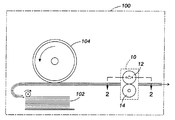
図1は、本開示に関連する従来技術の静電写真印刷機(ゼログラフィ印刷機やコピー機など)の主要部分を示す、簡略化された立面図である。デジタルまたはアナログコピー機、「レーザプリンタ」、イオノグラフィプリンタ、または他の装置の形態であることが可能な印刷装置100は、スタック102から基板(用紙などの被印刷物)を引き出し、チャージレセプタ(電荷受容体)104の表面からトナー画像を各用紙に取得させ、周知のプロセスによって用紙の上に静電潜像を形成および現像する機構を含む。
FIG. 1 is a simplified elevational view showing the main parts of a prior art electrostatographic printing machine (such as a xerographic printing machine or copier) relevant to the present disclosure. A
ある特定の用紙がチャージレセプタ104からマーキング材料を取得した後、その用紙(この時点では印刷用紙)は、全体が10で示される定着装置を通される。典型的な設計の定着装置10は、定着ロール12および加圧ロール14を含む。定着ロール12および加圧ロール14は連係して、それらの間に形成されたニップの全体にわたって互いに圧力をかけ合う。用紙がニップを通過するときに、加圧ロールに対する定着ロールの圧力が、画像を用紙に定着させることに寄与する。定着ロール12はさらに、圧力に加えて熱が用紙に供給されることによって定着プロセスがさらに促進されることができるように、ロールの表面を加熱する手段を含む。典型的には、定着ロール12は、これに関連付けられた加熱手段を有し、定着されるべき画像を有するシート面と接する。
After a particular sheet obtains marking material from the
一般に、定着ロール12内で所望の熱を発生させるために最もよく用いられる手段は、定着ロール12の内側の1つ以上の加熱エレメントであり、これらの加熱エレメントから発生した熱が、定着ロール12の外側表面を所望温度に到達させる。従来技術に関しては、加熱エレメントの様々な構成について、既に説明した。基本的には、加熱エレメントは、電力の印加に対する反応として特定量の熱を出力する任意の材料からなることが可能であり、そのような発熱材料は、当技術分野において周知である。
In general, the most commonly used means for generating the desired heat within the
図2は、図1の線2−2で切断した定着ロール12の断面図である。図2は、印刷装置の典型的な実施形態による定着ロール12の加熱エレメントの構成を示す。図に示されるように、定着ロール12の内側に、20および22で示される2つの「ランプ」、すなわち、加熱エレメントを含む2つの構造物が配置される。ランプ20および22は、それぞれが定着ロール12の軸方向長さに沿って配置され、したがって、定着装置10のニップを通り抜ける用紙の通過方向に対してほぼ垂直に配置されることになる。
FIG. 2 is a cross-sectional view of the
図2に示されるように、各ランプ(20など)は、特定の構成の発熱材料を含む。この具体的な例では、発熱材料の比較的長い主要部分24と、26で示される、発熱材料の複数の小さな部分とが、すべて直列に接続される。各ランプ(20または22など)の中では、定着ロール12のある一端に向かって主要部分24が配置され、比較的小さい部分26が定着ロール12の他端に向かって配置される。一実施形態では、発熱材料は概ねタングステンからなり、ランプの全体的な構造物はホウケイ酸ガラスであり、これらの材料は、定着ランプに関してはごく一般的である。
As shown in FIG. 2, each lamp (such as 20) includes a specific configuration of heat generating material. In this particular example, a relatively long
典型的には、定着ロール12の温度を調節する制御システムは、40および42で示されるような温度センサ(サーミスタ)を含み、そのそれぞれは、定着ロール12の表面の局所温度を監視する。サーミスタ(40および42など)は、定着ロール12の中点に対して対称的に取り付けられることが好ましい。このようにして、各サーミスタ40、42は、2つのランプに沿って同等の場所に直接隣接して位置する。サーミスタのこの構成は、より大きな制御システムの動作を改善する。
Typically, the control system that regulates the temperature of the
図3は、本開示の特定の実施形態を説明するために、加熱エレメント70とインターフェースされ、セグメント化されたヒーターを制御するヒーターコントローラシステム30を示す。加熱エレメント70には、3つのセクションS1、S2、およびS3が定義されている。セクションS1、S2、およびS3のそれぞれは、AC電源50から供給されるAC電圧を印加されることによって加熱されるように構成される。各セクションS1、S2、およびS3は、印加される電圧の符号に応じて、個別に加熱されるか、他のセクションと一緒に加熱される。たとえば、加熱エレメント70の特定のセクションまたはセクションの組み合わせは、AC波形の負の半周期の間に加熱されるか、或いはAC波形の正の半周期の間に加熱されるように構成される。このように、定着装置10に送られる被印刷物のサイズに応じて定着ロール12の外側表面の特定部分を加熱するように、AC位相制御によって、加熱エレメント70の個々のセクションS1、S2、およびS3が制御される。定着装置10への被印刷物の送りについての説明では、横方向給紙(LEF)および縦方向給紙(SEF)という用語を使用すると便利である。加熱エレメント70は、3つの異なる被印刷物サイズ(たとえば、用紙サイズ)、すなわち、A5 SEF、11インチSEF、および11インチLEFをサポートするように構成される。一般に、A5用紙のSEFは約148mmであり、11インチ用紙のSEFは約215.9mmであり、11インチ用紙のLEFは約279.4mmである。したがって、A5 SEF用紙は、セクションS1の加熱によってサポートされ、11インチSEF用紙は、セクションS1およびS2の組み合わせの加熱によってサポートされ、11インチLEF用紙は、セクションS1、S2、およびS3の組み合わせの加熱によってサポートされる。
FIG. 3 shows a
図3を参照すると、コントローラシステム30は、計算および制御を実行するCPU(図示省略)と、第1および第2の双方向スイッチまたはトライアックP1およびP2と、AC電源50と、サーミスタT1、T2、およびT3と、スイッチまたはダイオードD1と、を含む。トライアックP1およびP2、ならびにサーミスタT1、T2、およびT3は、たとえばバス(図示省略)による接続を介して、CPUとインターフェースされる。サーミスタT1、T2、およびT3は、定着ロール12の外側表面と軽く接触する形で保持され、図3には説明目的でのみ含まれていることを理解されたい。セクションS1の終端(端子)は接合部J1を画定し、セクションS3の終端(端子)は接合部J2を画定する。セクションS1およびS2は、センタタップ60で区切られる。センタタップ60は、ダイオードD1のカソードと直列接続される。ダイオードD1のアノードは、接合部J2においてセクションS3の終端と接続される。トライアックP1と加熱エレメント70とは、接合部J1で直列接続され、トライアックP2と加熱エレメント70とは、セクションS2とセクションS3との間で直列接続され、これらの直列回路は、並列に電源50に接続される。トライアックP1およびP2は、CPUから受け取る信号のハイ/ローレベルによって、オン/オフされる。電子は、電源50が供給するAC電圧の正の半周期の導通フェーズ(位相)の間に電源50に向かって動き、負の半周期の導通フェーズ(位相)の間に電源50から遠ざかるように動くことを理解されたい。
Referring to FIG. 3, the
ヒーターコントローラシステム30はさらに、T1、T2、およびT3で示されるような温度センサ(サーミスタ)を含み、それらのそれぞれは、定着ロール12の表面と軽く接触する形で保持され、それによって、サーミスタT1、T2、およびT3は、加熱エレメント70のそれぞれセクションS1、S2、およびS3に対応する、定着ロール12の表面のセクションの局所温度を監視する。稼働時には、セクションS1、S2、およびS3が、それぞれサーミスタT1、T2、およびT3によって監視されながら、定着ロール12の表面を、定着の実行に最適な所定温度F1まで加熱する。サーミスタT1、T2、およびT3による検出の結果は、CPUに入力される。
The
被印刷物のサイズおよび方向の検知については、当技術分野において周知である。たとえば、この検知は、任意の好適な自動測定/検知技術によって可能であり、または、サイズおよび方向の情報を定着装置10のユーザインターフェースからCPUに手動入力することによっても可能である。A5 SEF給紙実行に最適化された第1の動作モードでは、A5 SEF用紙サイズ情報が、定着装置10によって自動的に検知されるか、ユーザによって手動入力される。用紙サイズ情報が受け取られるか、サーミスタT1によって検出される温度が温度F1を下回ると、トライアックP1が、電源50から供給されるAC波形の正負両方の半周期(位相)の間に導通する(ONとなる)ようCPUからトリガされ、それによって、電流が電源50から短絡接続を通ってセンタタップ60に流れることが可能になる。AC波形の正負両方の半周期(位相)の間に生じた熱が、接合部J1によってシンク(蓄積)される。このようにして、セクションS1が定着ロール12の外側表面を温度F1まで加熱する。外側表面温度は、サーミスタT1によって監視される。外側表面温度が温度F1を超えると、加熱エレメント70のセクションS1への電力が低減される。第1の動作モードの間、トライアックP2は、電源50から供給されるAC波形のどの半周期でも、導通するようトリガされない。
Sensing the size and orientation of the substrate is well known in the art. For example, this detection can be by any suitable automatic measurement / detection technique, or by manually inputting size and orientation information from the user interface of the
11インチSEF給紙実行に最適化された第2の動作モードでは、11インチSEF用紙サイズ情報が、定着装置10によって検知されるか、ユーザによって手動入力される。用紙サイズ情報が受け取られるか、サーミスタT1によって検出される温度が温度F1を下回ると、トライアックP1が、電源50から供給されるAC波形の負の半周期(位相)の間に導通する(ONとなる)ようCPUからトリガされ、トライアックP2が、電源50から供給されるAC波形の正の半周期(位相)の間に導通する(ONとなる)ようCPUからトリガされる。これにより、電流が電源50から短絡接続を通ってセンタタップ60に流れることが可能になる。AC波形の負の半周期(位相)の間に生じた熱は、接合部J1によってシンクされ、AC波形の正の半周期(位相)の間に生じた熱は、接合部J2によってシンクされる。AC波形の正の半周期(位相)の間、ダイオードD1の両端の電圧は、D1の導通方向とは逆向きの電圧(逆バイアス)となるため、第2の動作モードの間はダイオードD1に電流が流れない。このようにして、加熱エレメント70のセクションS1およびS2が、定着ロール12の外側表面を温度F1まで加熱する。外側表面温度は、サーミスタT1およびT2によって監視される。検出された外側表面温度が温度F1を超えると、加熱エレメント70のセクションS1および/またはS2への電力が低減される。
In the second operation mode optimized for 11-inch SEF paper feed execution, 11-inch SEF paper size information is detected by the fixing
11インチLEF給紙実行に最適化された第3の動作モードでは、11インチLEF用紙サイズ情報が、定着装置10によって検知されるか、ユーザによって手動入力される。用紙サイズ情報が受け取られるか、サーミスタT1によって検出される温度が温度F1を下回ると、トライアックP1が、電源50から供給されるAC波形の正の半周期(位相)の間に導通する(ONとなる)ようCPUからトリガされ、トライアックP2が、電源50から供給されるAC波形の負の半周期(位相)の間に導通する(ONとなる)ようCPUからトリガされる。これにより、電流が電源50から短絡接続を通ってセンタタップ60に流れることが可能になる。トライアックP1の正の半周期(位相)の間に生じた熱は、接合部J1によってシンクされ、トライアックP2の負の半周期(位相)の間に生じた熱は、接合部J2によってシンクされる。AC波形の負の半周期(位相)の間、ダイオードD1は導通状態となるため、ダイオードD1に電流が流れる。このようにして、11インチLEFの実行のために、セクションS2およびS3の両方がAC波形の負の半周期(位相)の間に加熱され、同じく11インチLEFの実行のために、セクションS1がAC波形の正の半周期(位相)の間に加熱される。具体的には、加熱エレメント70のセクションS1、S2、およびS3が、定着ロール12の外側表面を温度F1まで加熱する。外側表面温度は、サーミスタT1、T2、およびT3によって監視される。検出された外側表面温度が温度F1を超えると、加熱エレメント70のセクションS1、S2、および/またはS3への電力が低減される。
In the third operation mode optimized for 11-inch LEF paper feed execution, 11-inch LEF paper size information is detected by the fixing
次に、図4を参照して、本発明の別の実施形態によるヒーターコントローラシステム35について説明する。コントローラシステム35は、加熱エレメント80および90とインターフェースされる。加熱エレメント80は、2つのセクションS4およびS5によって画定される。セクションS4およびS5のそれぞれは、電源55から供給されるAC電圧を印加されることによって加熱されるように構成される。加熱エレメント80は、異なる2つの被印刷物サイズ、すなわち、A5 SEFおよび11インチSEFをサポートするように構成される。加熱エレメント90は、加熱エレメント80との組み合わせで、さらに2つの被印刷物サイズ、すなわち、11インチLEFおよびA4 LEFをサポートするように構成される。
Next, a
コントローラシステム35は、計算および制御を実行するCPU(図示省略)と、第1および第2の双方向スイッチまたはトライアックP3およびP4と、AC電源55と、サーミスタT4、T5、T6、およびT7と、スイッチまたはダイオードD2、D3、D4、およびD5と、を含む。サーミスタT4、T5、T6、およびT7は、定着ロール12の外側表面と軽く接触する形で保持され、図4には説明目的でのみ含まれていることを理解されたい。トライアックP3およびP4、ならびにサーミスタT4、T5、T6、およびT7は、たとえばバス(図示省略)による接続を介して、CPUとインターフェースされる。ダイオードD2およびD4は、印加されたAC電圧の負の半周期の間のみ導通するように構成される。ダイオードD3およびD5は、印加されたAC電圧の正の半周期の間のみ導通するように構成される。
The
図4の加熱エレメント80においては、セクションS4の終端(端子)が接合部J3を画定し、セクションS5の終端が接合部J4を画定する。ダイオードD3のアノードは、電源55に直列接続され、ダイオードD3のカソードは、接合部J4においてセクションS5の終端に直列接続される。ダイオードD2のアノードは、接続部J3においてセクションS4の終端に直列接続され、ダイオードD2のカソードは、ダイオードD3のアノードに直列接続される。図4の加熱エレメント90においては、セクションS6の終端が接合部J5を画定し、セクションS7の終端が接合部J6を画定する。ダイオードD5のカソードは、接合部J5においてセクションS6の終端に直列接続され、ダイオードD5のアノードは、ダイオードD4のカソードに直列接続される。ダイオードD4のアノードは、接合部J6においてセクションS7の終端に直列接続される。
In the
トライアックP3と加熱エレメント80とは、セクションS4とセクションS5との間で直列接続され、トライアックP4と加熱エレメント90とは、セクションS6とセクションS7との間で直列接続され、これらの直列回路は、並列に電源55に接続される。トライアックP3およびP4は、CPUから受け取る信号のハイ/ローレベルによって、オン/オフされる。
The triac P3 and the
ヒーターコントローラシステム35はさらに、T4、T5、T6、およびT7で示されるような温度センサ(サーミスタ)を含み、それらのそれぞれは、定着ロール12の表面と軽く接触する形で保持され、それによって、サーミスタT4、T5、T6、およびT7は、加熱エレメント80および90のそれぞれセクションS4、S5、S6、およびS7に対応する、定着ロール12の表面の区画の局所温度を監視する。稼働時には、セクションS4、S5、S6、およびS7が、それぞれサーミスタT4、T5、T6、およびT7によって監視されながら、定着ロール12の表面を、定着の実行に最適な所定温度F2まで加熱する。サーミスタT4、T5、T6、およびT7による検出の結果は、CPUに入力される。
The
A5 SEF給紙実行に最適化された第1の動作モードでは、A5 SEF用紙サイズ情報が、定着装置10によって検知されるか、ユーザによって手動入力される。用紙サイズ情報が受け取られるか、サーミスタT4によって検出される温度が温度F2を下回ると、トライアックP3が、電源55から供給されるAC波形の負の半周期(位相)の間に導通する(ONとなる)ようCPUからトリガされる。これによりダイオードD2に電流が流れることが可能となり、トライアックP3の負の半周期(位相)の間に生じた熱がJ3によってシンク(蓄積)される。このようにして、加熱エレメント80のセクションS4が、定着ロール12の外側表面を温度F2まで加熱する。外側表面温度は、サーミスタT4によって監視される。外側表面温度が温度F2を超えると、セクションS4への電力が低減される。第1の動作モードの間、トライアックP4は、電源55から供給されるAC波形のどの半周期(位相)でも、導通する(ONとなる)ようトリガされない。
In the first operation mode optimized for A5 SEF paper feed execution, the A5 SEF paper size information is detected by the fixing
11インチSEF用紙サイズ給紙実行に最適化された第2の動作モードでは、11インチSEF用紙サイズ情報が、定着装置10によって検知されるか、ユーザによって手動入力される。用紙サイズ情報が受け取られるか、サーミスタT5によって検出される温度が温度F2を下回ると、トライアックP3が、電源55から供給されるAC波形の正負両方の半周期(位相)の間に導通する(ONとなる)ようCPUからトリガされる。トライアックP3の負の半周期(位相)の間の導通によりダイオードD2に電流が流れることで、生じた熱が接合部J3によってシンク(蓄積)され、トライアックP3の正の半周期(位相)の間の導通によりダイオードD3に電流を流れることで、生じた熱が接合部J4によってシンク(蓄積)される。このようにして、加熱エレメント80のセクションS4およびS5が、定着ロール12の外側表面を温度F2まで加熱する。外側表面温度は、サーミスタT4およびT5によって監視される。外側表面温度が温度F2を超えると、セクションS4および/またはS5への電力が低減される。第2の動作モードの間、トライアックP4は、電源55から供給されるAC波形のどの半周期(位相)でも、導通するようトリガされない。
In the second operation mode optimized for the 11-inch SEF paper size paper feed, 11-inch SEF paper size information is detected by the fixing
11インチLEF用紙サイズ給紙実行に最適化された第3の動作モードでは、11インチLEF用紙サイズが、定着装置10によって検知されるか、ユーザによって手動入力される。用紙サイズ情報が受け取られるか、サーミスタT6によって検出される温度が温度F2を下回ると、トライアックP3が、電源55から供給されるAC波形の正負両方の半周期の間に導通するようCPUからトリガされ、トライアックP4が、電源55から供給されるAC波形の正の半周期(位相)の間に導通する(ONとなる)ようCPUからトリガされる。トライアックP4が導通する正の半周期(位相)の間は、ダイオードD5に電流が流れることで、生じた熱が接合部J5によってシンク(蓄積)される。このようにして、加熱エレメント80のセクションS4およびS5は、前述の第2の動作モードに従って、定着ロール12の外側表面を温度F2まで加熱し、エレメント90のセクションS6も、定着ロール12の外側表面を温度F2まで加熱する。外側表面温度は、サーミスタT4、T5、およびT6によって監視される。外側表面温度が温度F2を超えると、セクションS4、S5、および/またはS6への電力が低減される。
In the third operation mode optimized for feeding 11-inch LEF paper size, the 11-inch LEF paper size is detected by the fixing
A4 LEF用紙サイズ給紙実行に最適化された第4の動作モードでは、A4 LEF用紙サイズ情報が、定着装置10によって検知されるか、ユーザによって手動入力される。用紙サイズ情報が受け取られるか、サーミスタT7によって検出される温度が温度F2を下回ると、トライアックP3が、電源55から供給されるAC波形の正負両方の半周期(位相)の間に導通する(ONとなる)ようCPUからトリガされ、トライアックP4も、電源55から供給されるAC波形の正負両方の半周期(位相)の間に導通する(ONとなる)ようCPUからトリガされる。トライアックP4が導通する正の半周期(位相)の間は、ダイオードD5に電流が流れることで、生じた熱が接合部J5によってシンク(蓄積)され、トライアックP4が導通する負の半周期(位相)の間は、ダイオードD4に電流が流れることで、生じた熱が接合部J6によってシンク(蓄積)される。このようにして、加熱エレメント80のセクションS4およびS5は、前述の第2の動作モードに従って、定着ロール12の外側表面を温度F2まで加熱し、エレメント90のセクションS6およびS7も、定着ロール12の外側表面を温度F2まで加熱する。外側表面温度は、サーミスタT4、T5、T6、およびT7によって監視される。外側表面温度が温度F2を超えると、セクションS4、S5、S6、および/またはS7への電力が低減される。
In the fourth operation mode optimized for the A4 LEF paper size paper feed, the A4 LEF paper size information is detected by the fixing
ヒーターコントローラシステム35は、加熱エレメント80および90のそれぞれの1つのセクションでのみ電力を受け取ることによって加熱エレメント80および90に電力を供給することが可能であるように簡略化することも可能であることを理解されたい。具体的には、各加熱エレメントの1つのセクションに電力を供給したときに、AC波形をミラーリングしてAC正弦波を完成させることが可能である。これによって、電力が供給されていないセクションに電力が与えられる。たとえば、加熱エレメントのセクションS5に、電源55から供給されるAC波形の正の半周期(位相)の間に、電力を供給する。このAC波形をミラーリングすることによって、AC波形の負の半周期(位相)の間にセクションS4に電力を供給する。この構成では、サーミスタT4が、加熱エレメント80の全体に対応する、定着ロール12の表面温度を監視する。同様に、サーミスタT6が、加熱エレメント90の全体に対応する、定着ロール12の表面温度を監視する。サーミスタT5およびT7は、温度を監視し、印刷の実行に必要な電力を要求することによって、加熱エレメント80および90をそれぞれ制御するように構成される。
The
10 定着装置
12 定着ロール
14 加圧ロール
20、22 ランプ
24、26 発熱材料
30、35、ヒーターコントローラシステム
40、42 サーミスタ
50、55 AC電源
60 センタタップ
70、80、90 加熱エレメント
100 印刷装置
102 スタック
104 チャージレセプタ
DESCRIPTION OF
Claims (3)
直列に接続された第1〜第3のセクションを有する加熱エレメントと、
前記加熱エレメントにAC波形による電力を供給する電源と、
前記ヒーターコントローラシステムが、前記被印刷物の特定のサイズに各々対応する少なくとも2つの動作モードのうちの1つのモードで動作している間に、前記第1〜第3のセクションのうちの少なくとも1つに、前記電源から供給された電流を選択的に与えるように構成された、第1及び第2の双方向スイッチ、及びダイオードと、
を備え、
前記AC波形の正負の一方の位相の間に、前記第1及び第2のセクションのうちの少なくとも1つに電力が供給され、
前記AC波形の正負の他方の位相の間に前記第1〜第3のセクションのうちの少なくとも他方に電力が供給され、
第1及び第2のセクションが第1接合部で接続され、第2及び第3のセクションが第2接合部で接続され、
第1の双方向スイッチが第1のセクションの第1接合部と反対側の終端に接続され、第2の双方向スイッチが第2接合部に接続され、ダイオードのカソードが第1接合部に接続され、ダイオードのアノードが第3のセクションの、第2接合部と反対側の終端に接続され、第1接合部とダイオードのカソードとが結合されて前記電源に接続され、
前記AC波形の正負両方の位相の間に第1の双方向スイッチをONにすることで、第1のセクションに電力を供給し、
前記AC波形の負位相の間に第1の双方向スイッチをONにし、前記AC波形の正位相の間に第2の双方向スイッチをONにすることで、前記第1及び第2のセクションに電力が供給され、
前記AC波形の正位相の間に第1の双方向スイッチをONにし、前記AC波形の負位相の間に第2の双方向スイッチをONにすることで、前記第1〜第3のセクションに電力が供給される、
ヒーターコントローラシステム。 In a printing system, a heater controller system for a fixing device configured to fix a marking material to a substrate,
A heating element having first to third sections connected in series;
A power supply for supplying electric power with an AC waveform to the heating element;
While the heater controller system is operating in one of at least two modes of operation each corresponding to a particular size of the substrate, at least one of the first to third sections. First and second bidirectional switches and diodes configured to selectively provide a current supplied from the power source;
With
Power is provided to at least one of the first and second sections during one of the positive and negative phases of the AC waveform;
Power is supplied to at least the other of the first to third sections during the other positive or negative phase of the AC waveform ;
The first and second sections are connected at the first junction, the second and third sections are connected at the second junction,
The first bidirectional switch is connected to the end of the first section opposite the first junction, the second bidirectional switch is connected to the second junction, and the cathode of the diode is connected to the first junction. The anode of the diode is connected to the end of the third section opposite to the second junction, the first junction and the cathode of the diode are coupled and connected to the power source,
Powering the first section by turning on the first bi-directional switch during both positive and negative phases of the AC waveform;
By turning on the first bidirectional switch during the negative phase of the AC waveform and turning on the second bidirectional switch during the positive phase of the AC waveform, the first and second sections Power is supplied,
By turning on the first bidirectional switch during the positive phase of the AC waveform and turning on the second bidirectional switch during the negative phase of the AC waveform, the first to third sections Power is supplied,
Heater controller system.
直列に接続された第1及び第2のセクションを有する第1の加熱エレメントと、
直列に接続された第3及び第4のセクションを有する第2の加熱エレメントと、
前記第1および第2の加熱エレメントにAC波形による電力を供給する電源と、
前記ヒーターコントローラシステムが、各々が前記被印刷物の特定のサイズに対応する少なくとも2つの動作モードのうちの1つのモードで動作している間に、前記第1および第2の加熱エレメントのうちの少なくとも一方の、前記少なくとも2つのセクションのうちの少なくとも1つのセクションに、前記電源から供給された電流を選択的に与えるように構成された、第1及び第2の双方向スイッチ及び第1〜第4のダイオードと、
を備え、
前記AC波形の正負の一方の位相の間に、前記第1および第2の加熱エレメントの一方の2つのセクションのうちの少なくとも1つに電力が供給され、
前記AC波形の正負の他方の位相の間に、前記第1および第2の加熱エレメントの一方の2つのセクションのうちの少なくとも他方に電力が供給されるよう制御され、
第1及び第2のセクションが第1接合部で接続され、第3及び第4のセクションが第2接合部で接続され、
第1の双方向スイッチが第1接合部に接続され、第2の双方向スイッチが第2接合部に接続され、第1のダイオードのアノードが第1のセクションの、第1接合部と反対側の終端に接続され、第2のダイオードのカソードが第2のセクションの、第1接合部と反対側の終端に接続され、第3のダイオードのアノードが第4のセクションの、第2接合部と反対側の終端に接続され、第4のダイオードのカソードが第3セクションの、第2接合部と反対側の終端に接続され、第1のダイオードのカソードと第2のダイオードのアノードが結合されて電源に接続され、第3のダイオードのカソードと第4のダイオードのアノードが結合されて電源に接続され、
前記AC波形の負位相の間に第1の双方向スイッチをONにすることで、第1のセクションに電力を供給し、
前記AC波形の正負両方の位相の間に第1の双方向スイッチをONにすることで、第1及び第2のセクションに電力を供給し、
前記AC波形の正負両方の位相の間に第1の双方向スイッチをONにすると共に、正位相の間に第2の双方向スイッチをONにすることで、第1〜第3セクションに電力を供給し、
前記AC波形の正負両方の位相の間に第1及び第2の双方向スイッチをONにすることで、第1〜第4のセクションに電力を供給する、
ヒーターコントローラシステム。 In a printing system, a heater controller system for a fixing device configured to fix a marking material to a substrate,
A first heating element having first and second sections connected in series;
A second heating element having third and fourth sections connected in series;
A power supply for supplying power by an AC waveform to the first and second heating elements;
While the heater controller system is operating in one of at least two modes of operation each corresponding to a particular size of the substrate, at least one of the first and second heating elements The first and second bidirectional switches and the first to fourth switches configured to selectively supply current supplied from the power source to at least one of the at least two sections. A diode of
With
Power is supplied to at least one of the two sections of one of the first and second heating elements during one of the positive and negative phases of the AC waveform;
Controlled to supply power to at least the other of the two sections of one of the first and second heating elements during the other positive or negative phase of the AC waveform ;
The first and second sections are connected at the first junction, the third and fourth sections are connected at the second junction,
The first bidirectional switch is connected to the first junction, the second bidirectional switch is connected to the second junction, and the anode of the first diode is on the opposite side of the first section from the first junction. The cathode of the second diode is connected to the end of the second section opposite to the first junction, and the anode of the third diode is connected to the second junction of the fourth section. Connected to the opposite end, the cathode of the fourth diode is connected to the end of the third section opposite the second junction, and the cathode of the first diode and the anode of the second diode are combined Connected to the power source, the cathode of the third diode and the anode of the fourth diode are combined and connected to the power source,
Powering the first section by turning on the first bidirectional switch during the negative phase of the AC waveform;
Powering the first and second sections by turning on the first bi-directional switch during both positive and negative phases of the AC waveform;
By turning on the first bidirectional switch during both positive and negative phases of the AC waveform and turning on the second bidirectional switch during the positive phase, power is supplied to the first to third sections. Supply
Power is supplied to the first to fourth sections by turning on the first and second bidirectional switches during both positive and negative phases of the AC waveform.
Heater controller system.
Applications Claiming Priority (2)
| Application Number | Priority Date | Filing Date | Title |
|---|---|---|---|
| US11/542,534 | 2006-10-03 | ||
| US11/542,534 US7623819B2 (en) | 2006-10-03 | 2006-10-03 | Heater controller system for a fusing apparatus of a xerographic printing system |
Publications (3)
| Publication Number | Publication Date |
|---|---|
| JP2008090302A JP2008090302A (en) | 2008-04-17 |
| JP2008090302A5 JP2008090302A5 (en) | 2010-12-16 |
| JP5063278B2 true JP5063278B2 (en) | 2012-10-31 |
Family
ID=38982557
Family Applications (1)
| Application Number | Title | Priority Date | Filing Date |
|---|---|---|---|
| JP2007249754A Expired - Fee Related JP5063278B2 (en) | 2006-10-03 | 2007-09-26 | Xerographic printing system and heater controller system for fixing device |
Country Status (5)
| Country | Link |
|---|---|
| US (1) | US7623819B2 (en) |
| EP (1) | EP1909146B1 (en) |
| JP (1) | JP5063278B2 (en) |
| CN (1) | CN101158838B (en) |
| DE (1) | DE602007002599D1 (en) |
Families Citing this family (3)
| Publication number | Priority date | Publication date | Assignee | Title |
|---|---|---|---|---|
| US9563158B2 (en) | 2014-10-24 | 2017-02-07 | Xerox Corporation | Tap for a solid resistive heater element |
| US9798279B2 (en) | 2015-07-01 | 2017-10-24 | Xerox Corporation | Printed thermocouples in solid heater devices |
| JP6817532B2 (en) * | 2016-10-19 | 2021-01-20 | 株式会社リコー | Fixing device, image forming device |
Family Cites Families (32)
| Publication number | Priority date | Publication date | Assignee | Title |
|---|---|---|---|---|
| US3609402A (en) | 1969-11-03 | 1971-09-28 | Gen Electric | Monostable multivibrator with dual function commutation and timing capacitor |
| US4434353A (en) * | 1981-09-30 | 1984-02-28 | Xerox Corporation | Fusing system |
| JPS61221755A (en) * | 1986-02-19 | 1986-10-02 | Hitachi Ltd | Recording parts having amorphous si-ge type layer |
| US5029311A (en) | 1990-09-28 | 1991-07-02 | Xerox Corporation | Stabilized fluorescent lamp for a document scanning system |
| JPH04372977A (en) | 1991-06-24 | 1992-12-25 | Fuji Xerox Co Ltd | Heater control device for image forming device |
| DE69332233T2 (en) * | 1992-03-31 | 2003-04-17 | Canon Kk | Image heater with control of the actuation of several heating elements |
| JP3298982B2 (en) | 1993-06-10 | 2002-07-08 | キヤノン株式会社 | Image forming device |
| JPH0980972A (en) * | 1995-09-11 | 1997-03-28 | Ushio Inc | Heating/fixing device |
| JPH10143003A (en) * | 1996-11-06 | 1998-05-29 | Ricoh Co Ltd | Thermal fixing device |
| EP1016941B1 (en) * | 1997-09-18 | 2005-11-16 | Canon Finetech Inc. | Fixing heater controlling method and an image forming device |
| JP3389475B2 (en) | 1997-09-19 | 2003-03-24 | シャープ株式会社 | Image forming device |
| JPH11233235A (en) * | 1998-02-16 | 1999-08-27 | Fuji Xerox Co Ltd | Heating control method, heater, and fixing device |
| JP3848001B2 (en) * | 1999-02-15 | 2006-11-22 | キヤノン株式会社 | Heat fixing device and image forming apparatus |
| BR0003627A (en) | 1999-08-16 | 2001-04-03 | Xerox Corp | Flicker-free fuser control |
| JP2002174989A (en) * | 2000-09-28 | 2002-06-21 | Ricoh Co Ltd | Fixing device and image forming device |
| US6353718B1 (en) | 2000-11-17 | 2002-03-05 | Xerox Corporation | Xerographic fusing apparatus with multiple heating elements |
| US6568792B2 (en) | 2000-12-11 | 2003-05-27 | Xerox Corporation | Segmented heater configurations for an ink jet printhead |
| JP2004013016A (en) | 2002-06-10 | 2004-01-15 | Toshiba Tec Corp | Fixing device and image forming apparatus |
| JP4317383B2 (en) * | 2002-06-19 | 2009-08-19 | 株式会社リコー | Image forming apparatus |
| US6777653B2 (en) | 2002-09-26 | 2004-08-17 | Emerson Electric Co. | Igniter controller |
| JP2004207159A (en) * | 2002-12-26 | 2004-07-22 | Canon Inc | Heating device |
| US6901226B2 (en) | 2003-05-19 | 2005-05-31 | Xerox Corporation | Power control for a xerographic fusing apparatus |
| JP4599176B2 (en) * | 2004-01-23 | 2010-12-15 | キヤノン株式会社 | Image heating apparatus and heater used in the apparatus |
| JP4673620B2 (en) * | 2004-02-02 | 2011-04-20 | 株式会社リコー | Image forming apparatus, power supply control method, and power supply control program |
| JP2005284093A (en) * | 2004-03-30 | 2005-10-13 | Canon Inc | Image forming apparatus |
| JP4522138B2 (en) * | 2004-05-07 | 2010-08-11 | キヤノン株式会社 | Heat fixing device |
| US7283145B2 (en) * | 2004-06-21 | 2007-10-16 | Canon Kabushiki Kaisha | Image heating apparatus and heater therefor |
| JP4557623B2 (en) * | 2004-07-29 | 2010-10-06 | キヤノン株式会社 | Image forming apparatus |
| KR20060018305A (en) * | 2004-08-24 | 2006-03-02 | 삼성전자주식회사 | The fuser controller with the sensing means of the paper size and the image forming device |
| KR100636166B1 (en) | 2004-09-01 | 2006-10-19 | 삼성전자주식회사 | Apparatus for forming image on the print media |
| US7333743B2 (en) * | 2004-09-09 | 2008-02-19 | Ricoh Company, Ltd. | Fixing device, image forming apparatus including the fixing device, and fixing method |
| US7049750B1 (en) | 2005-06-15 | 2006-05-23 | Osram Sylvania Inc. | Lamp having integral voltage controller |
-
2006
- 2006-10-03 US US11/542,534 patent/US7623819B2/en not_active Expired - Fee Related
-
2007
- 2007-09-26 JP JP2007249754A patent/JP5063278B2/en not_active Expired - Fee Related
- 2007-10-04 EP EP07117882A patent/EP1909146B1/en not_active Expired - Fee Related
- 2007-10-04 DE DE602007002599T patent/DE602007002599D1/en active Active
- 2007-10-08 CN CN200710162226.1A patent/CN101158838B/en not_active Expired - Fee Related
Also Published As
| Publication number | Publication date |
|---|---|
| DE602007002599D1 (en) | 2009-11-12 |
| US7623819B2 (en) | 2009-11-24 |
| EP1909146B1 (en) | 2009-09-30 |
| JP2008090302A (en) | 2008-04-17 |
| CN101158838A (en) | 2008-04-09 |
| CN101158838B (en) | 2012-02-15 |
| EP1909146A1 (en) | 2008-04-09 |
| US20080080886A1 (en) | 2008-04-03 |
Similar Documents
| Publication | Publication Date | Title |
|---|---|---|
| JP6173414B2 (en) | Image heating device | |
| JP2004302362A (en) | Fixing device and image forming apparatus | |
| JPH10221986A (en) | Image forming device and heater for heating for heating/ fixing device | |
| JP2007018912A (en) | Heater and heating device | |
| JP2007025237A (en) | Fixing device and image forming apparatus | |
| JP2013029726A (en) | Image heating device and heating body used in this image heating device | |
| US7412181B2 (en) | Multivariate predictive control of fuser temperatures | |
| JP2017167462A (en) | Image heating device | |
| JP6727783B2 (en) | Image heating device and image forming device | |
| JP5063278B2 (en) | Xerographic printing system and heater controller system for fixing device | |
| JP5074711B2 (en) | Image heating apparatus and heating body used in the apparatus | |
| JP2023016472A (en) | Image forming apparatus | |
| JP2011107447A (en) | Image forming apparatus | |
| JP2000340336A (en) | Roll-shaped heater and fixing device using it | |
| JP2009103881A (en) | Heating element and heater | |
| JP4208773B2 (en) | Fixing device and heater used in the fixing device | |
| JP7292906B2 (en) | Fixing device and image forming device | |
| JP2006047630A (en) | Heating body, fixing device, and image forming apparatus | |
| JP2002123113A (en) | Fixing device and image forming device with the same | |
| JP2012078453A (en) | Fixing heater, fixing device, and image forming apparatus | |
| JP2004294779A (en) | Fixing device and image-forming apparatus | |
| JP2002351255A (en) | Image forming device | |
| JP2007206615A (en) | Image heating device and image forming apparatus | |
| JP2004318128A (en) | Fixing device and image forming apparatus | |
| JP2020085955A (en) | Image forming apparatus, control method for image forming apparatus, and program |
Legal Events
| Date | Code | Title | Description |
|---|---|---|---|
| A621 | Written request for application examination |
Free format text: JAPANESE INTERMEDIATE CODE: A621 Effective date: 20100924 |
|
| A521 | Request for written amendment filed |
Free format text: JAPANESE INTERMEDIATE CODE: A523 Effective date: 20101027 |
|
| A977 | Report on retrieval |
Free format text: JAPANESE INTERMEDIATE CODE: A971007 Effective date: 20110527 |
|
| A131 | Notification of reasons for refusal |
Free format text: JAPANESE INTERMEDIATE CODE: A131 Effective date: 20110607 |
|
| A521 | Request for written amendment filed |
Free format text: JAPANESE INTERMEDIATE CODE: A523 Effective date: 20110804 |
|
| A131 | Notification of reasons for refusal |
Free format text: JAPANESE INTERMEDIATE CODE: A131 Effective date: 20120327 |
|
| A521 | Request for written amendment filed |
Free format text: JAPANESE INTERMEDIATE CODE: A523 Effective date: 20120622 |
|
| TRDD | Decision of grant or rejection written | ||
| A01 | Written decision to grant a patent or to grant a registration (utility model) |
Free format text: JAPANESE INTERMEDIATE CODE: A01 Effective date: 20120710 |
|
| A01 | Written decision to grant a patent or to grant a registration (utility model) |
Free format text: JAPANESE INTERMEDIATE CODE: A01 |
|
| A61 | First payment of annual fees (during grant procedure) |
Free format text: JAPANESE INTERMEDIATE CODE: A61 Effective date: 20120807 |
|
| R150 | Certificate of patent or registration of utility model |
Free format text: JAPANESE INTERMEDIATE CODE: R150 |
|
| FPAY | Renewal fee payment (event date is renewal date of database) |
Free format text: PAYMENT UNTIL: 20150817 Year of fee payment: 3 |
|
| LAPS | Cancellation because of no payment of annual fees |