JP5059999B2 - Insert device for crawler chain assembly - Google Patents
Insert device for crawler chain assembly Download PDFInfo
- Publication number
- JP5059999B2 JP5059999B2 JP2001121036A JP2001121036A JP5059999B2 JP 5059999 B2 JP5059999 B2 JP 5059999B2 JP 2001121036 A JP2001121036 A JP 2001121036A JP 2001121036 A JP2001121036 A JP 2001121036A JP 5059999 B2 JP5059999 B2 JP 5059999B2
- Authority
- JP
- Japan
- Prior art keywords
- seal groove
- link
- ring member
- collar
- seal
- Prior art date
- Legal status (The legal status is an assumption and is not a legal conclusion. Google has not performed a legal analysis and makes no representation as to the accuracy of the status listed.)
- Expired - Fee Related
Links
Images


Classifications
-
- B—PERFORMING OPERATIONS; TRANSPORTING
- B62—LAND VEHICLES FOR TRAVELLING OTHERWISE THAN ON RAILS
- B62D—MOTOR VEHICLES; TRAILERS
- B62D55/00—Endless track vehicles
- B62D55/08—Endless track units; Parts thereof
- B62D55/18—Tracks
- B62D55/20—Tracks of articulated type, e.g. chains
- B62D55/205—Connections between track links
Description
【0001】
【発明の属する技術分野】
本発明は、一般に履帯式作業機械用の履帯チェーンアセンブリに関し、より詳細には、履帯チェーンアセンブリ用のインサート装置に関する。
【0002】
【従来の技術】
履帯式作業機械は、通常、スプロケット、遊動輪、及び、履帯チェーンアセンブリを持つ。作業機械の使用時には、スプロケットが回転して履帯チェーンアセンブリに係合し、それによって履帯チェーンアセンブリをスプロケット及び遊動輪によって形成される経路の周りに回転させる。履帯チェーンアセンブリの回転によって、作業機械は地上を推進し、様々な作業機能を実行する。
履帯チェーンアセンブリは、一般に1対の平行なチェーンを含んでおり、各平行チェーンは、一連の連行履帯リンクでできている。履帯チェーンアセンブリは、平行チェーンの間に挟み込まれ、それと結合された一連のブシュ及び履帯ピンを更に含む。ブシュ及び連行履帯リンクは、共働して多くの履帯ジョイントを形成し、それにより、例えば履帯チェーンアセンブリがスプロケット及び遊動輪の周囲を回転する時など、履帯チェーンアセンブリを使用する間における履帯リンクに対するブシュの必要な動きを可能にする。
【0003】
履帯接合部は、通常、履帯シールアセンブリを装備し、履帯チェーンがその使用時に曝される水、ほこり、砂、岩、又は、他の鉱物又は化学元素の様々な腐食性及び研磨性混合物が侵入するのを防いでいる。履帯シールアセンブリはまた、潤滑油を履帯接合部内に保持し、ブシュ及び履帯リンクの前記相対運動を容易にするように機能する。
前記の機能を果たすために使用される、ある従来技術履帯シールアセンブリは、内部に溝が形成された履帯リンクを利用している。シール部材は、溝内部に置かれ、次に、研磨されたブシュ面に対して摺動封止係合するように、弾性ゴム装荷リングがシール部材を軸線方向に押し込む。しかし、上記の装置を使用する時、いくつかの問題が発生してきた。
【0004】
【発明が解決しようとする課題】
そのような問題の1つは、ブシュ面の溝削りに関係している。履帯チェーンアセンブリの作業環境で見出される様々な研磨性粒子の混合物は、ブシュ面内部に溝を磨耗することができる優れた研磨合成物を作る傾向がある。これらの溝が十分な深さに達する場合、履帯シールアセンブリの一体性が危うくなり、研磨性粒子が履帯接合部に侵入する可能性がある。これらの溝はまた、履帯接合部内に収容されている潤滑剤が漏出する経路をもたらす。上記で検討した全ての問題は、履帯接合部の故障、すなわち履帯チェーンアセンブリの故障をもたらす可能性がある。一旦履帯チェーンアセンブリが故障すると、例えばブシュ、履帯リンク、及び、シール部材など、様々なその部品を交換し、履帯チェーンアセンブリを組み立て直す必要がある。履帯チェーンアセンブリの磨耗部品を取り除き同じものを組み立て直す工程は相当量の時間を要し、すなわち、作業機械の生産性を低減する。
従って、上記の欠点を一つ又はそれ以上克服する履帯チェーンアセンブリ用のインサート装置が求められている。
【0005】
【課題を解決するための手段】
本発明の1つの実施形態により、履帯チェーンアセンブリ用のインサート装置が準備される。該インサート装置は、(i)第1の側壁、(ii)第2の側壁、(iii)それらを貫通して形成された内腔、(iv)第1の側壁に形成された第1のシール溝、及び、(v)第2の側壁に形成された第2のシール溝、を持つリング部材を含む。
本発明の別の実施形態により、履帯チェーンアセンブリ用のインサート装置が準備される。該インサート装置は、(i)第1の側壁、(ii)第2の側壁、(iii)それらを貫通して形成された内腔、(iv)第1の側壁に形成された第1のシール溝、及び、(v)第2の側壁に形成された第2のシール溝、を持つリング部材を含む。該インサート装置はまた、開口が形成されたリンクを含む。該リンクは、リング部材が開口内に置かれるようにリング部材に対して置かれる。該インサート装置は、リング部材の内腔の内部に置かれる履帯ピンを更に含む。
【0006】
本発明の更に別の実施形態により、履帯チェーンアセンブリ用のインサート装置が準備される。該インサート装置は、(i)第1の側壁、(ii)第2の側壁、(iii)それらを貫通して形成された内腔、(iv)第1の側壁に形成された第1のシール溝、及び、(v)第2の側壁に形成された第2のシール溝、を持つリング部材を含む。該インサート装置はまた、(i)内部を通って形成された通路と(ii)ブシュ末端面とを持つブシュを含む。該ブシュは、(i)通路が内腔と直線状に位置合わせされ、(ii)第1のシール溝がブシュ末端面と相対する関係で位置するように、該リング部材に対して置かれる。該インサート装置は、開口が形成されたリンクを更に含む。該リンクは、該リング部材が開口内に置かれるように、該リング部材に対して置かれる。
【0007】
【発明の実施の形態】
ここで図1を参照すると、中に本発明の形態を組み込んだ作業機械10が示されている。作業機械10は、フレーム11、及び、全てフレーム11に搭載されたエンジンアセンブリ13及び運転台アセンブリ15を含む。作業機械10はまた、機械的にフレーム11に結合されたブレードなどの作業器具17を含む。作業機械10は、フレーム11に機械的に結合された下部走行体アセンブリ12を更に含む。
下部走行体アセンブリ12は、駆動スプロケット19、1対の遊動輪21及び23、及び、遊動輪21及び23の間に挟まれた多数のローラアセンブリ25を含む。(本発明はまた、楕円形システムにおいても利用できることに注意されたい。)下部走行体アセンブリ12はまた、履帯チェーンアセンブリ14を含む。作業機械10を使用する間、駆動スプロケット19は、回転して履帯チェーンアセンブリ14と係合し、それにより、履帯チェーンアセンブリ14を、駆動スプロケット19と遊動輪21及び23とによって形成された経路の周りを回転させる。作業機械10は、履帯チェーンアセンブリ14の回転によって地面上を推進され、様々な作業機能を実行する。
【0008】
図2及び図3に更に明瞭に示されるように、履帯チェーンアセンブリ14は、各サブアセンブリ20に装着されたクローラシュー214(図1参照)を備える多数のサブアセンブリを含む。以下にきわめて詳細に論じるように、各サブアセンブリ20は、履帯チェーンアセンブリ14が閉ループを形成するように、隣接するサブアセンブリ20と外部リンク18及び外部リンク18aにより機械的に結合されている。履帯チェーンアセンブリ14の閉ループは、上記の方式で機能するように、駆動スプロケット19、遊動輪21及び23、及び、ローラアセンブリ25の周りに配置される。
各サブアセンブリ20は、カートリッジアセンブリ22、カートリッジアセンブリ22a、内部リンク16、及び、内部リンク16aを含む。カートリッジアセンブリ22aは、カートリッジアセンブリ22と実質的に同一であり、従って、カートリッジアセンブリ22のみが本明細書において以下に詳細に説明される。
【0009】
図4A、図4B、及び、図4Cに示すように、カートリッジアセンブリ22は、内部を貫通して形成された通路26を持つブシュ24、履帯ピン28、内部を貫通して形成された内腔38を持つインサート36、及び、内部を貫通して形成された内腔54を持つインサート52を含む。インサート52は、実質的にインサート36と同一であり、従って、インサート36のみを本明細書において説明することを理解されたい。カートリッジアセンブリ22はまた、内部に形成された孔42を持つカラー40を含む。カートリッジアセンブリ22はまた、カラー40と実質的に同一である別のカラー56を含む。特に、カラー56はまた、内部に形成された孔58を含む。
【0010】
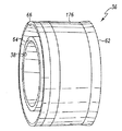
ここで図15及び図16を参照すると、インサート36は、側壁62及び側壁64を持つリング部材176を含む。シール溝50は、シール溝50が内腔38の中心軸線180と同心になるように側壁62に形成される。側壁62にシール溝50を形成することによって上部壁セグメント246及び下部壁セグメント248が形成されることになり、シール溝50は、上部壁セグメント246と下部壁セグメント248との間に設けられることになる。上部壁セグメント246は、中心軸線180と実質的に平行な関係にあるリング部材176の主外面252の直線上の延長250と内面300の直線上の延長254とが角度φを形成するように中心軸線180から離れるように傾斜している内面300を持つ。好ましくは、角度φは約5°である(角度φは、図15では明瞭に示すためにいくらか誇張して示されていることに注意されたい)。
【0011】
側壁64はまた、内部に内腔38の中心軸線180と同心に形成されたシール溝66を持つ。リング部材176の上部壁セグメント258は、上部壁セグメント246について上記で説明したのと実質的に同一方式で中心軸線180から離れるように傾斜していることを理解されたい。
シール溝50は、幅W1及び半径R1を持つ。半径R1がここで意味するのは、図15に示すように中心軸線180とシール溝50の内壁セグメント182との間の距離である。シール溝66もまた、幅W2及び半径R2を持つ。上記で説明したのと同様な方式で、半径R2がここで意味するのは、図15に示すように中心軸線180とシール溝66の内壁セグメント184との間の距離である。好ましくは、幅W1は、幅W2と実質的に等しい。半径R1が半径R2と実質的に等しいこともまた好ましい。
【0012】
図4Aに戻って参照すると、シール溝50は、内部に配置された(i)環状スラスト部材76、及び、(ii)環状シール部材72を持つ。スラスト部材76及びシール部材72は、スラスト部材76がシール部材72を矢印186で示すような軸線方向に押し込むようにシール溝50に置かれる。上記で説明した方式で上部壁セグメント246を中心軸線180から遠ざかるように傾斜させることにより、環状スラスト部材76と環状シール部材72とをシール溝50内へ挿入することが、真っ直ぐつまり角度の付かない上部壁セグメントを持つ他のシール溝設計に比較して容易になることを理解されたい。特に、上部壁セグメント246の傾斜により、環状スラスト部材76と環状シール部材72とをシール溝50内に挿入するのに利用される機械類の能力が高められる。同様な方式で、シール溝66は、内部に配置された(i)環状スラスト部材78、及び、(ii)環状シール部材74を持つ。スラスト部材78及びシール部材74は、シール溝66に置かれ、スラスト部材78がシール部材74を矢印188で示す軸線方向に押し込むようになっている。上記で示す通り、リング部材176の上部壁セグメント258を中心軸線180から離れるように傾斜させたことはまた、環状スラスト部材78と環状シール部材74とをシール溝66内へ挿入するのに利用される機械類の能力を高める。
【0013】
同様な方式で、インサート52の環状シール溝60は、内部に配置された(i)環状シール部材92、及び、(ii)環状スラスト部材190を持つ。スラスト部材190及びシール部材92は、シール溝60に置かれ、スラスト部材190がシール部材92を矢印192で示す軸線方向に押し込むようになっている。インサート52の環状シール溝84はまた、内部に配置された(i)環状スラスト部材194、及び、(ii)環状シール部材86を持つ。スラスト部材194及びシール部材86は、シール溝84に置かれ、スラスト部材194がシール部材86を矢印198で示す軸線方向に押し込むようになっている。
両シール溝をインサートに形成したのは好ましいことではあるが、シール溝をカラー側壁に形成することもまた考慮される。その場合、シール部材及びスラスト部材は、カラー側壁に形成されたシール溝に配置される。この実施形態においては、インサートの1つの側壁がカラーのシール溝に配置されたシール部材の支持面として働く。スラスト部材がカラーと一体化できることもまた考慮される。加えて、スラスト部材がインサートと一体化できることもまた考慮される。
【0014】
ここで図4A、図4B、及び、図4Cを参照すると、履帯ピン28は、ブシュ24の通路26内に挿入され、ブシュ24が履帯ピン28に対して矢印200及び204によって示される方向に回転できるようになっている(図4B参照)。インサート36は、(i)履帯ピン28の一部分32が内腔38を通って延び、(ii)シール溝50がブシュ24の端面68に対向する関係になるように、履帯ピン28及びブシュ24に対して置かれる。インサート36は、更に、シール部材72が環状スラスト部材76によってブシュ24の端面68に押しつけられるようにブシュ24に対して置かれる。インサート36が長手方向軸線30の周りをブシュ24及び履帯ピン28の双方に対して矢印200及び204が示す方向に回転できることを理解されたい(図4B参照)。
【0015】
カラー40は、(i)履帯ピン28の一部分34が孔42内へ延び、(ii)カラー40の端面70がシール溝66と対向する関係になるように、履帯ピン28及びインサート36に対して置かれる。カラー40は、更に、環状シール部材74がスラスト部材78によってカラー40の端面70に押しつけられるようにインサート36に対して置かれる。カラー40が(i)履帯ピン28に対して回転できず、又は、(ii)履帯ピン28に対して軸線方向に動けないように、カラー40は、履帯ピン28に対して固定される。例えば、カラー40は、履帯ピン28にレーザ溶接することができる。上記で説明した方式でカラー40を履帯ピン28に装着することは、履帯チェーン14の端部の遊びに対する制御を高める。
【0016】
インサート52及びカラー56は、インサート36及びカラー40に関して上記で説明したのと同様な方式で、履帯ピン28及びブシュ24に対して置かれる。特に、インサート52は、(i)履帯ピン28の一部分が内腔54を通って延び、(ii)シール溝84がブシュ24の端面88に対向する関係になるように、履帯ピン28及びブシュ24に対して置かれる。インサート52は、更に、シール部材86がスラスト部材194によってブシュ24の端面88に押しつけられるようにブシュ24に対して置かれる。インサート52がブシュ24及び履帯ピン28の双方に対して矢印200及び204が示す方向に回転できることを理解されたい(図4B参照)。
【0017】
カラー56は、(i)履帯ピン28の一部分が孔58内へ延び、(ii)カラー56の端面90がシール溝60と対向する関係になるように、履帯ピン28及びインサート52に対して置かれる。カラー56は、更に、シール部材92がスラスト部材190によってカラー56の端面90に押しつけられるようにインサート52に対して置かれる。カラー56が履帯ピン28に対して回転できず、又は、履帯ピン28に対して軸線方向に移動できないように、カラー56は、履帯ピン28に対して固定される。例えば、カラー56は、履帯ピン28にレーザ溶接することができる。上記で説明した方式でカラー56を履帯ピン28に装着することはまた、履帯チェーン14の端部の遊びに対する制御を高める。
【0018】
図4Aに示すように、履帯ピン28は、内部に形成された潤滑油リザーバ44を持つ。潤滑油リザーバ44は、潤滑流路46と流体連絡し、潤滑流路46は、履帯ピン28の外面48に通じる。1対のプラグ200が潤滑油リザーバ44内に位置し、オイルなどの潤滑油が潤滑油リザーバ44から漏れるのを防ぐ。カートリッジアセンブリ22を使用する間、潤滑油リザーバ44内に配置されたオイルは、潤滑流路46を通って履帯ピン28の外面48へ進む。一旦外面48に配置されると、オイルは、インサート36、ブシュ24、及び、インサート52が履帯ピン28に対して回転するのを容易にする。オイルはまた、シール部材72、74、86、及び、92を潤滑する。
シール部材72、74、86、及び、92、スラスト部材76、78、109、及び、194、カラー端面70及び90、及び、ブッシュ端面68及び88は、全て共働してオイルをカートリッジアセンブリ22内に保持する一方、デブリ(例えば、砂や岩など)が入らないようにする。
【0019】
ここで図5から図10を参照すると、内部リンク16が示されている。内部リンク16a、外部リンク18、及び、内部リンク18aは、全て内部リンク16と実質的に同一であるので、従って、ここでは内部リンク16のみが詳細に説明されることになるのを理解されたい。
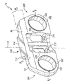
内部リンク16は、(i)側面96、(ii)側面98、(iii)本体部材94を通って形成された開口100、(iv)本体部材94を通って形成された開口102、(v)軌道面114、及び、(vi)シュー表面116を持つ本体部材94を含む。本体部材94はまた、内部に形成された1対の出口孔120及び122を持つ。しかし、例えば無支柱リンク設計ではただ1つの出口孔しか利用できないことを理解されたい。両出口孔120及び122は、開口100及び開口102に挟まれているのが好ましい。ボルト孔210は、各出口孔120及び122の内部に置かれる。各ボルト孔210は、各ボルト孔210が軌道面114の最も広い部分に対して横方向の中心になるように軌道面114と位置合わせされる点を理解されたい。ボルト孔210を利用して、クローラシュー214を内部リンク16のシュー表面116に固定する。その上、図11に示すように、内部リンク16は、壁セグメント240及び壁セグメント242を持つ。壁セグメント242は、壁セグメント240の直線上の延長244と壁セグメント242とが約20°の角度σを形成するように、壁セグメント240に対して角度を付けられる。壁セグメント242は、履帯チェーンアセンブリ14のローラフランジ(図示しない)との案内接触面として機能する。上記で説明した方式で各リンクの壁セグメント242に角度を付けることは、履帯チェーンアセンブリ14を使用する間、それを案内するローラフランジの能力を高める。
【0020】
本体部材94は、(i)軌道面114と中心軸線118との間(すなわち、角度α)、及び、シュー表面116と中心軸線118との間(すなわち、角度β)が実質的に90°を形成するような本体部材94を通る中心軸線118を持つことを理解されたい。その上、本体部材94は、中心軸線118に関して対称である点を理解されたい。ここで言う対称とは、中心軸線118などの中央分割線の両側が同一又は一致する性質である。中心軸線118によって形成される本体部材94の各半分は、その対応する半分の鏡像である点を更に理解されたい。
内部リンク16はまた、本体部材94の側面96から外側へ延びる延長部材104を含む。延長部材104は、そこに形成された点P1を持つ。内部リンク16はまた、本体部材94の側面96から外側へ延びる延長部材106を含む。延長部材106は、そこに形成された点P2を持つ。内部リンク16は、本体部材94の側面96から外側へ延びる延長部材108を更に含む。延長部材108は、そこに形成された点P3を持つ。
【0021】
延長部材104、延長部材106、及び、延長部材108は、(i)互いに間隔を開けて離れ、(ii)好ましくは開口100と開口102との間に挟まれる。加えて、延長部材104上に形成された点P1、延長部材106上に形成された点P2、及び、延長部材108上に形成された点P3は、第1の平面を形成する。その上、本体部材94の側面96は、外面110を持つ。外面110は、そこに形成された点P4、そこに形成された点P5、及び、そこに形成された点P6を持つ。点P4、点P5、及び、点P6は、第1の平面と実質的に平行な関係にある第2の平面を形成する。好ましくは、(i)開口100及び開口102は、点P4と点P5との間に挟まれており、(ii)第2の平面は、延長部材104、延長部材106、及び、延長部材108だけによって交差される点を理解されたい。
本体部材94の側面98はまた、外面112を持つ。外面112は、そこに形成された点P7、そこに形成された点P8、及び、そこに形成された点P9を持つ。点P7、点P8、及び、点P9は、第1の平面と実質的に平行な関係にある第3の平面を形成する。好ましくは、開口100及び開口102は、点P7と点P8との間に挟まれている。1対の機械加工ボス302は、開口100及び102を囲むために外面112上に配置される。更に、機械加工ボス302以外の本体部材94のどの部分も第3の平面と交差して側面98から外側へ延長しないことが好ましい。
【0022】
(i)開口100と開口102とが同一平面上にあり、(ii)各側面96及び98が比較的平坦であり、(iii)リンク16の側面96から外側へ延びたどの延長部材104、106、及び、108も外面110と平行である平面を形成する、そのようなリンク16を持つことが本発明にとって有利であることを理解されたい。例えば、上記の特性を持つリンクを持つことは、平面的平行接触面を持つリンクをもたらす。平面的平行接触面を持つことは、リンク製造工程、履帯チェーン14組立工程、及び、履帯チェーン14分解工程の間、リンク16を適切に位置する能力を促進する。加えて、内部リンク16a、外部リンク18、及び、外部リンク18aが全て内部リンク16と実質的に同一であることによって、他の履帯チェーンアセンブリ設計で通常用いられる構造的に異なった「右利きリンク」と「左利きリンク」とを持つ必要性が排除される。従って、履帯チェーンアセンブリ14を組み立てるためには、1つの型のリンクのみ(すなわちリンク16であって、リンク16a、18、及び、18aはリンク16と実質的に同一)を製造すればよく、そのことによって履帯チェーンアセンブリ14の製造コストが単純化され低減される。
【0023】
その上、中心軸線118について対称なリンク16の本体部材94を持つことは、リンク16の各端部206及び208(図5及び図10参照)に均等な材料分布をもたらす。対称リンク16、及び、各端部206及び208の均等な材料分布を持つことは有利である。それは、例えば(i)設計及び解析技術、(ii)鍛造法及びツーリング、(iii)位置決め及び加工法、及び、ツーリング、及び、(iv)熱処理装置を簡単にする。従って、本発明の1つの態様は、比較的低開発製造コストのリンク16を準備する。
その上、図3及び図10に示すように、軌道面114は、幅W3を持ち、シュー表面116は、実質的に幅W3と等しい幅W4を持つ。幅W3及び幅W4を実質的に等しくすることはまた、製造、組立、及び、分解工程の間、リンク16を位置決めすることを容易にする。
【0024】
上記の通り、各サブアセンブリ20は、カートリッジアセンブリ22、カートリッジアセンブリ22a、内部リンク16、及び、内部リンク16aを含む(図3参照)。特に、図3に示す通り、内部リンク16は、(i)カートリッジアセンブリ22のインサート52が内部リンク16の開口100内に位置し、(ii)カートリッジアセンブリ22aのインサート52aが内部リンク16の開口102内に位置し、(iii)延長部材104、106、及び、108が矢印224によって示す方向に外側を向くように、カートリッジアセンブリ22及びカートリッジ22aに対して置かれる。両インサート52及び52aは、開口100及び102内に圧入されることを理解されたい。インサート52及び52aが各々開口100及び102内に圧入されることによって、インサート52及び52aは、内部リンク16に対して回転することが不可能になる。しかし、ブシュ24及び24a、履帯ピン28及び28a、及び、カラー56及び56aは、矢印216、218、220、及び、222によって示す方向に内部リンク16に対して回転することが可能である。
【0025】
同様な方式で、内部リンク16aは、(i)カートリッジアセンブリ22のインサート36が内部リンク16aの開口100a内に位置し、(ii)カートリッジアセンブリ22aのインサート36aが内部リンク16aの開口102a内に位置し、(iii)延長部材104a、106a、及び、108aが矢印226によって示す方向に外側を向くように、カートリッジアセンブリ22及びカートリッジ22aに対して置かれる。両インサート36及び36aは、開口100a及び102a内に圧入されることを理解されたい。インサート36及び36aが各々開口100a及び102a内に圧入されることによって、インサート36及び36aが内部リンク16aに対して回転することが不可能になる。しかし、ブシュ24及び24a、履帯ピン28及び28a、及び、カラー40及び40aは、矢印216、218、220、及び、222によって示す方向にリンク16aに対して回転することが可能である。
【0026】
図2、図3、及び、図11に示すように、隣接するサブアセンブリ20は、1対の外部リンク18及び18aによって連結される。特に、外部リンク18は、(i)カラー56が外部リンク18の開口124内に置かれ、(ii)延長部材104、106、及び、108が矢印228によって示す方向に内側を向くように(図2参照)、サブアセンブリ20のカートリッジアセンブリ22に対して置かれる。加えて、外部リンク18は、約1.5ミリメートルの間隙が外部リンク18と内部リンク16との間に形成されるように内部リンク16に対して置かれる。この間隙は、全ての隣接する内部及び外部リンクの間に存在することを理解されたい。外部リンク18はまた、カートリッジアセンブリ22aのカラー56aが外部リンク18の開口126内に置かれるように、隣接するサブアセンブリ20のカートリッジアセンブリ22aに対して置かれる(図2参照)。両カラー56及び56aは、開口124及び126内に圧入されることを理解されたい。カラー56及び56aを開口124及び126に各々圧入することによって、カラー56及び56a、及び、履帯ピン28及び28aは、外部リンク18に対して回転することが不可能になる。しかし、ブシュ24及び24a、及び、インサート52及び52aは、外部リンク18に対して回転可能である。
【0027】
外部リンク18aは、(i)カラー40が外部リンク18aの開口124a内に置かれ、(ii)延長部材104a、106a、及び、108aが矢印230によって示す方向に内側を向くように、サブアセンブリ20のカートリッジアセンブリ22に対して置かれる(図2参照)。外部リンク18aはまた、カートリッジアセンブリ22aのカラー40aが外部リンク18aの開口126a内に置かれるように、前記隣接するサブアセンブリ20のカートリッジアセンブリ22aに対して置かれる(図2参照)。両カラー40及び40aは、開口124a及び126a内に圧入されることを理解されたい。カラー40及び40aを開口124a及び126a内に各々圧入することによって、カラー40及び40a、及び、履帯ピン28及び28aは、外部リンク18aに対して回転することが不可能になる。しかし、ブシュ24及び24a、及び、インサート36及び36aは、外部リンク18aに対して回転可能である。
【0028】
追加のサブアセンブリ20は、外部リンク18及び18aを上記の方式で利用しながら、適切な長さを持つ履帯チェーンアセンブリ14が得られるまで連結される。履帯チェーンアセンブリ14は、偶数のリンクから作られることが好ましい。履帯チェーンアセンブリ14が偶数のリンクで作られると、履帯チェーン14を組み立てるのにリンク16、16a、18、及び、18aしか必要としない。しかし、ある状況によっては、履帯チェーン14を奇数のリンクで作ることが要求される。図17に示すように、履帯チェーンアセンブリ14が奇数のリンクで作られると、履帯チェーンアセンブリ14は、リンク128及び128aを利用して構築される単一のサブアセンブリ170を含む必要がある。リンク128aは、リンク128と実質的に同一なので、ここではリンク128のみが詳細に説明されることを理解されたい。
【0029】
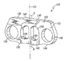
図14に示されるように、リンク128は、(i)側面132、(ii)側面134、(iii)本体部材130を通って形成された開口136、及び、(iv)本体部材130を通って形成された開口138を持つ本体部材130を含む。本体部材130の側面132は、上縁162及び下縁164を持つ。加えて、本体部材130の側面134は、上縁166及び下縁168を持つ(図13参照)。リンク128は、内部に出口孔154及び出口孔156を更に含む。しかし、無支柱リンク設計では出口孔を1つだけ利用できる点を理解されたい。出口孔154及び出口孔156は、開口136と開口138との間に挟まれる。リンク128はまた、本体部材130に形成されたボルト孔158及びボルト孔160を含む。ボルト孔158及びボルト孔160は、各々出口孔154及び出口孔156内に置かれる。リンク128はまた、本体部材130の側面132の上縁162から外向きに延びる延長部材140を含む。リンク128はまた、本体部材130の側面132の下縁164から外向きに延びる延長部材142を含む。延長部材142は、延長部材140から間隔を空けて置かれる。リンク128はまた、本体部材130の側面134の上縁166から外向きに延びる延長部材144を含む。リンク128は、本体部材130の側面134の下縁168から外向きに延びる延長部材146を更に含む。延長部材146は、延長部材144から間隔を空けて置かれる。本体部材130は、軌道面148及びシュー表面150を持つ。中心軸線152(図12及び図13参照)は、軌道面148及びシュー表面150を貫通し、実質的に90°の角度(すなわち、角度θ)を(i)軌道面148と中心軸線152との間で、及び、(ii)シュー表面150と中心軸線152との間で90°の角度(すなわち、角度φ)を形成する。本体部材130は、中心軸線152について対称である。詳細には、本体部材130は対称ではあるが、本体部材94に対して回転されている。
【0030】
側面132は、側面134とオフセットしているので、側面132は、側面134と同一平面上にはない。側面132と側面134とにオフセットがあることにより、履帯チェーン14に利用した時、隣接するリンク128との間に隙間を生じる。加えて、開口136は、開口138とオフセットしているので、開口136は、開口138と同一平面にはない。延長部材142及び延長部材146は、開口136と開口138とに挟まれている。
サブアセンブリ170は、図17に示すように、カートリッジアセンブリ22、カートリッジアセンブリ22a、リンク128、及び、リンク128aを含む。カートリッジアセンブリ22及びカートリッジアセンブリ22aは、図3に関連して前述したカートリッジアセンブリ22及びカートリッジアセンブリ22aと同一であることに注意されたい。リンク128は、(i)カートリッジアセンブリ22aのカラー40aが開口138に位置し、(ii)インサート36が開口136に位置するように、カートリッジアセンブリ22及び22aに対して置かれる。カラー40a及びインサート36は、各々開口138及び136内に圧入されることを理解されたい。同様な方式で、リンク128aは、(i)カートリッジアセンブリ22aのカラー56aが開口138aに位置し、(ii)インサート52が開口136aに位置するように、カートリッジアセンブリ22及び22aに対して置かれる。カラー56a及びインサート52は、各々開口138a及び136a内に圧入されることを理解されたい。
【0031】
サブアセンブリ170は、履帯チェーンアセンブリ14内に以下のような方式で組み込まれる。内部リンク16aは、(i)カートリッジアセンブリ22aのインサート36aが開口102a内に圧入され、(ii)その次に隣接するカートリッジアセンブリ22のインサート36が開口100a(図17に図示しない)内に圧入されるように、カートリッジアセンブリ22a及びその次に隣接するカートリッジアセンブリ22(図17に図示しない)に対して置かれる。内部リンク16は、(i)カートリッジアセンブリ22aのインサート52aが開口102a内に圧入され、(ii)その次に隣接するカートリッジアセンブリ22のインサート36が開口100a(図17に図示しない)内に圧入されるように、カートリッジアセンブリ22a及びその次に隣接するカートリッジアセンブリ22に対して置かれる。外部リンク18aは、(i)カートリッジアセンブリ22のカラー40が開口124a内に圧入され、(ii)その次に隣接するカートリッジアセンブリ22aのカラー40aが開口126a(図17に図示しない)内に圧入されるように、カートリッジ22及びその次に隣接するカートリッジアセンブリ22a(図17に図示しない)に対して置かれる。外部リンク18は、(i)カートリッジアセンブリ22のカラー56が開口124内に圧入され、(ii)その次に隣接するカートリッジアセンブリ22aのカラー56aが開口126a(図17に図示しない)内に圧入されるように、カートリッジ22及びその次に隣接するカートリッジアセンブリ22a(図17に図示しない)に対して置かれる。
【0032】
産業上の利用可能性
履帯チェーンアセンブリ14は、それに利用されるリンクに関して既に説明した利点に加え多くの利点を持つ。例えば、カートリッジアセンブリ22は、カートリッジアセンブリ22内の潤滑油の保持力を改善することによって履帯チェーンアセンブリ14の寿命を増加する。(カートリッジアセンブリ22に関して説明されたいかなる利点も、カートリッジアセンブリ22aに当てはまることを理解されたい。)更に、カートリッジアセンブリ22は、自己完備型構成要素であり、カラー40及び56は、履帯ピン28に永久的に取り付けてあるので(例えば、レーザ溶接により)、カートリッジアセンブリ22は、履帯ピン上に直接圧着されたリンクを利用する履帯チェーン設計に比べると、軸線方向終端遊びに対してより大きな制御をもたらす。その上、カートリッジアセンブリ22は、自己完備型であり、履帯チェーンアセンブリ14が必要とする実際上全ての封止及び支持機能をもたらすので、履帯チェーンアセンブリ14は、古い磨耗したカートリッジアセンブリ22を取り除き、新しいカートリッジアセンブリ22で置き換えることにより容易に修理可能である。履帯チェーンアセンブリ14を保守するためにカートリッジアセンブリ22全体を除去及び交換することは、部品方式で保守する必要がある他の履帯チェーンアセンブリ設計に比べ、対費用効果に優れて効率的である。
【0033】
カートリッジアセンブリ22において利用されるインサートはまた、幾つかの利点を持つ。(以下の利点は、カートリッジアセンブリ22で利用される全てのインサートに当てはまるが、インサート36のみを以下に検討することに注意されたい。)例えば、インサート36の一体化構造により、履帯チェーンアセンブリ14は、スラストワッシャやシール取付シュラウド無しで組み立てることができ、それにより、履帯チェーンアセンブリ14の機械的複雑性やコストが低減される。更に、インサート36の構造は、単一組立済みユニットにおける両シール部材72及び74のシール取付を準備する。加えて、インサート36の幾何学的形状により、比較的簡単に真っ直ぐな内腔38を製作することができる。インサート36の真っ直ぐな内腔は、リンク(例えば、内部リンク16)の開口内へ圧入される際、インサート36の撓み又は変形を容易にする。この変形又は撓みにより、インサート36が履帯ピン28との良好な軸受接触断面をもたらすことになる。
本発明の他の態様、対象、及び、利点は、図面、開示、及び、添付請求項を検討することにより得ることができる。
【図面の簡単な説明】
【図1】内部に本発明の形態を組み込んだ作業機械の側面図である。
【図2】図1の作業機械に対する履帯チェーンアセンブリのセグメントの平面図である。
【図3】図2に示す履帯チェーンアセンブリのサブアセンブリの平面図である。
【図4A】図2に示す履帯チェーンアセンブリのカートリッジアセンブリの長手方向断面図である。
【図4B】図4Aに示すカートリッジアセンブリの側面図である。
【図4C】図4Bに示すカートリッジアセンブリの端面図である。
【図5】図2に示す履帯チェーンアセンブリのリンクの全体図である。
【図6】図5に示すリンクの側面図である。
【図7】図5に示すリンクの別の側面図である。
【図8】図5に示すリンクの断面図である。
【図9】図5に示すリンクの別の断面図である。
【図10】図5に示すリンクの別の全体図である。
【図11】図2に示す履帯チェーンアセンブリを線11−11に沿って切り取り、矢印の方向から見た断面図である。
【図12】図2に示す履帯チェーンアセンブリにおいて使用できるオフセット・リンクの全体図である。
【図13】図12示すオフセット・リンクの別の全体図である。
【図14】図12示すオフセット・リンクの更に別の全体図である。
【図15】図4Aに示すカートリッジアセンブリのインサートの断面図である。
【図16】図15に示すインサートの全体図である。
【図17】図2に示す履帯チェーンアセンブリにおいて使用できる別のサブアセンブリの平面図である。
【符号の説明】
36 インサート
38 内腔
50、66 シール溝
62 側壁
176 リング部材
180 中心軸線
182、184 シール溝の内壁セグメント
246、258 上部壁セグメント
248 下部壁セグメント
250 主外面の直線上の延長
252 リング部材の主外面
254 内面の直線上の延長
300 内面
R1、R2 シール溝の半径
W1、W2 シール溝の幅
ψ 主外面の直線上の延長と内面の直線上の延長とが成す角度[0001]
BACKGROUND OF THE INVENTION
The present invention relates generally to crawler chain assemblies for crawler work machines, and more particularly to an insert device for a crawler chain assembly.
[0002]
[Prior art]
A crawler work machine typically has a sprocket, idler wheels, and a crawler chain assembly. In use of the work machine, the sprocket rotates and engages the track chain assembly, thereby rotating the track chain assembly around the path formed by the sprocket and idler wheels. As the crawler chain assembly rotates, the work machine propels the ground and performs various work functions.
A track chain assembly typically includes a pair of parallel chains, each parallel chain being made of a series of entrained track links. The track chain assembly further includes a series of bushes and track pins sandwiched between and coupled to the parallel chains. The bushings and the entrained track links work together to form a number of track joints so that the track links during the use of the track chain assembly, for example, when the track chain assembly rotates around the sprocket and idler wheel, Allows the necessary movement of the bush.
[0003]
The track joint is usually equipped with a track seal assembly and intruded by various corrosive and abrasive mixtures of water, dust, sand, rocks, or other minerals or chemical elements to which the track chain is exposed in use. To prevent it. The track seal assembly also functions to retain lubricant within the track joint and facilitate the relative movement of the bushing and track link.
One prior art track seal assembly used to perform the above functions utilizes a track link having a groove formed therein. The seal member is placed inside the groove and then the elastic rubber loaded ring pushes the seal member axially so that it is in sliding sealing engagement with the polished bushing surface. However, several problems have occurred when using the above devices.
[0004]
[Problems to be solved by the invention]
One such problem is related to bushing grooving. The mixture of various abrasive particles found in the work environment of the crawler chain assembly tends to make an excellent abrasive composite that can wear grooves inside the bushing surface. If these grooves reach a sufficient depth, the integrity of the track seal assembly can be compromised and abrasive particles can enter the track joint. These grooves also provide a path for the lubricant contained within the track joint to leak out. All of the problems discussed above can lead to track joint failure, i.e. failure of the track chain assembly. Once the track chain assembly fails, it is necessary to replace various parts thereof, such as bushings, track links, and seal members, and reassemble the track chain assembly. The process of removing the worn parts of the track chain assembly and reassembling the same takes a considerable amount of time, i.e. reduces the productivity of the work machine.
Accordingly, there is a need for an insert device for a crawler chain assembly that overcomes one or more of the above disadvantages.
[0005]
[Means for Solving the Problems]
According to one embodiment of the present invention, an insert device for a crawler chain assembly is provided. The insert device includes (i) a first side wall, (ii) a second side wall, (iii) a lumen formed therethrough, and (iv) a first seal formed on the first side wall. A ring member having a groove and (v) a second seal groove formed in the second side wall.
In accordance with another embodiment of the present invention, an insert device for a crawler chain assembly is provided. The insert device includes (i) a first side wall, (ii) a second side wall, (iii) a lumen formed therethrough, and (iv) a first seal formed on the first side wall. A ring member having a groove and (v) a second seal groove formed in the second side wall. The insert device also includes a link in which an opening is formed. The link is placed against the ring member so that the ring member is placed in the opening. The insert device further includes a crawler pin positioned within the lumen of the ring member.
[0006]
According to yet another embodiment of the present invention, an insert device for a crawler chain assembly is provided. The insert device includes (i) a first side wall, (ii) a second side wall, (iii) a lumen formed therethrough, and (iv) a first seal formed on the first side wall. A ring member having a groove and (v) a second seal groove formed in the second side wall. The insert device also includes a bushing having (i) a passage formed therethrough and (ii) a bushing end face. The bushing is placed against the ring member such that (i) the passage is aligned linearly with the lumen and (ii) the first seal groove is positioned relative to the bushing end face. The insert device further includes a link having an opening formed therein. The link is placed against the ring member such that the ring member is placed in the opening.
[0007]
DETAILED DESCRIPTION OF THE INVENTION
Referring now to FIG. 1, a
The undercarriage assembly 12 includes a drive sprocket 19, a pair of idler wheels 21 and 23, and a number of roller assemblies 25 sandwiched between the idler wheels 21 and 23. (Note that the present invention can also be utilized in an elliptical system.) The undercarriage assembly 12 also includes a
[0008]
As more clearly shown in FIGS. 2 and 3, the
Each
[0009]
As shown in FIGS. 4A, 4B, and 4C, the
[0010]
Referring now to FIGS. 15 and 16, the
[0011]
The
[0012]
Referring back to FIG. 4A, the
[0013]
In a similar manner, the
While it is preferred that both seal grooves be formed in the insert, it is also contemplated that the seal grooves be formed in the collar sidewall. In that case, the seal member and the thrust member are disposed in a seal groove formed in the collar side wall. In this embodiment, one side wall of the insert serves as a support surface for the seal member disposed in the collar seal groove. It is also contemplated that the thrust member can be integrated with the collar. In addition, it is also contemplated that the thrust member can be integrated with the insert.
[0014]
Referring now to FIGS. 4A, 4B, and 4C, the
[0015]
The
[0016]
[0017]
The
[0018]
As shown in FIG. 4A, the
The
[0019]
Referring now to FIGS. 5-10, the
The
[0020]
The
[0021]
The
The
[0022]
(I) the
[0023]
Moreover, having the
Moreover, as shown in FIGS. 3 and 10, the
[0024]
As described above, each
[0025]
In a similar manner, the
[0026]
As shown in FIGS. 2, 3 and 11,
[0027]
The outer link 18a includes the
[0028]
[0029]
As shown in FIG. 14, the
[0030]
Since the
As shown in FIG. 17, the subassembly 170 includes a
[0031]
The subassembly 170 is incorporated into the
[0032]
Industrial Applicability The
[0033]
The insert utilized in the
Other aspects, objects, and advantages of the present invention can be obtained from a study of the drawings, the disclosure, and the appended claims.
[Brief description of the drawings]
FIG. 1 is a side view of a work machine incorporating an embodiment of the present invention therein.
2 is a plan view of a segment of a track chain assembly for the work machine of FIG. 1. FIG.
3 is a plan view of a subassembly of the crawler chain assembly shown in FIG. 2. FIG.
4A is a longitudinal cross-sectional view of the cartridge assembly of the crawler chain assembly shown in FIG.
4B is a side view of the cartridge assembly shown in FIG. 4A. FIG.
4C is an end view of the cartridge assembly shown in FIG. 4B. FIG.
5 is an overall view of a link of the crawler chain assembly shown in FIG. 2. FIG.
6 is a side view of the link shown in FIG. 5. FIG.
FIG. 7 is another side view of the link shown in FIG. 5;
8 is a cross-sectional view of the link shown in FIG.
9 is another cross-sectional view of the link shown in FIG.
FIG. 10 is another overall view of the link shown in FIG. 5;
11 is a cross-sectional view of the crawler chain assembly shown in FIG. 2 taken along line 11-11 and viewed from the direction of the arrows.
12 is an overall view of an offset link that can be used in the crawler chain assembly shown in FIG.
13 is another overall view of the offset link shown in FIG. 12. FIG.
14 is still another overall view of the offset link shown in FIG. 12. FIG.
15 is a cross-sectional view of the insert of the cartridge assembly shown in FIG. 4A.
16 is an overall view of the insert shown in FIG.
17 is a plan view of another subassembly that can be used in the crawler chain assembly shown in FIG. 2. FIG.
[Explanation of symbols]
36
Claims (4)
開口が形成され、前記リング部材が前記開口内に位置するように前記リング部材に対して配置されたリンクと、
前記リング部材の前記内腔を通して配置された履帯ピンと、
内部を通って形成された孔と、カラー末端面とを持ち、前記カラー末端面が前記リング部材の前記第1の側壁に対向するように前記リング部材に対して配置され、前記孔が前記リング部材の前記内腔と直線状に位置合わせされて、該孔に前記履帯ピンが通されたカラーと、
内部を通って形成された通路と、ブシュ末端面とを持ち、前記ブシュ末端面が前記リング部材の前記第1の側壁に対向するように前記リング部材に対して配置され、前記通路が前記リング部材の前記内腔と直線状に位置合わせされて、該通路に前記履帯ピンが通されたブシュと、
を含み、
前記リング部材には、前記第1の側壁に第1のシール溝が、前記第2の側壁に第2のシール溝が、それぞれ形成され、
前記カラーは、前記リング部材に形成された前記第1のシール溝が前記カラー末端面と相対する関係で位置するように、前記リング部材に対して配置され、
前記ブシュは、前記リング部材に形成された前記第2のシール溝が前記ブシュ末端面と相対する関係で位置するように、前記リング部材に対して配置され、
前記第1のシール溝には、第1のシール部材と、該第1のシール部材を前記カラーの前記カラー末端面に向けて軸線方向に付勢する第1のスラスト部材とが配置され、
前記第2のシール溝には、第2のシール部材と、該第2のシール部材を前記ブシュの前記ブシュ末端面に向けて軸線方向に付勢する第2のスラスト部材とが配置された
ことを特徴とする、履帯チェーンアセンブリ用のインサート装置。 Formed in a ring shape, the ring member having a first sidewall, a second sidewall, and said first and second lumen formed through the side wall,
An opening is formed, and links the ring member is disposed relative to the ring member to so that to position within said opening,
A crawler belt pin disposed through the lumen of the ring member;
A hole formed through the interior and a collar end surface, the collar end surface being disposed relative to the ring member such that the collar end surface faces the first side wall of the ring member; A collar aligned linearly with the lumen of the member and having the crawler pin passed through the hole;
A passage formed through the interior and a bushing end surface, the bushing end surface being disposed relative to the ring member so as to face the first side wall of the ring member; A bushing linearly aligned with the lumen of the member and having the crawler pin passed through the passage;
Only including,
The ring member is formed with a first seal groove on the first side wall and a second seal groove on the second side wall, respectively.
The collar is disposed with respect to the ring member such that the first seal groove formed in the ring member is positioned in a relationship relative to the collar end surface;
The bush is disposed with respect to the ring member such that the second seal groove formed in the ring member is positioned in a relationship opposed to the bushing end surface;
In the first seal groove, a first seal member and a first thrust member for urging the first seal member in the axial direction toward the collar end surface of the collar are disposed,
In the second seal groove, a second seal member and a second thrust member that urges the second seal member in the axial direction toward the bushing end surface of the bush are arranged. An insert device for a crawler belt chain assembly.
前記第1のシール溝は、前記上部壁セグメントと前記下部壁セグメントとの間に形成され、
前記上部壁セグメントは、前記中心軸線から離れる方向に傾斜する、
ことを特徴とする請求項2に記載のインサート装置。Said ring member further includes a top wall segment, the lower wall segment and the central axis extending through said lumen,
The first seal groove is formed between the upper wall segment and the lower wall segment;
The upper wall segment is inclined in a direction away from the central axis;
The insert device according to claim 2 .
前記第2のシール溝は、幅W2を持ち、
前記第1のシール溝は、半径R1を持ち、
前記第2のシール溝は、半径R2を持ち、
前記幅W1は、幅W2と等しく、
前記半径R1は、半径R2と等しい、
ことを特徴とする請求項1又は請求項2に記載のインサート装置。It said first seal groove has a width W 1,
It said second seal groove has a width W 2,
It said first seal groove has a radius R 1,
It said second seal groove has a radius R 2,
The width W 1 is equal to the width W 2 ,
The radius R 1 is equal to the radius R 2 ,
The insert device according to claim 1 or 2 , characterized by the above.
Applications Claiming Priority (2)
| Application Number | Priority Date | Filing Date | Title |
|---|---|---|---|
| US09/553914 | 2000-04-20 | ||
| US09/553,914 US6386651B1 (en) | 2000-04-20 | 2000-04-20 | Insert arrangement for a track chain assembly |
Publications (2)
| Publication Number | Publication Date |
|---|---|
| JP2001354176A JP2001354176A (en) | 2001-12-25 |
| JP5059999B2 true JP5059999B2 (en) | 2012-10-31 |
Family
ID=24211288
Family Applications (1)
| Application Number | Title | Priority Date | Filing Date |
|---|---|---|---|
| JP2001121036A Expired - Fee Related JP5059999B2 (en) | 2000-04-20 | 2001-04-19 | Insert device for crawler chain assembly |
Country Status (4)
| Country | Link |
|---|---|
| US (1) | US6386651B1 (en) |
| JP (1) | JP5059999B2 (en) |
| DE (1) | DE10116533A1 (en) |
| IT (1) | ITTO20010325A1 (en) |
Families Citing this family (25)
| Publication number | Priority date | Publication date | Assignee | Title |
|---|---|---|---|---|
| US6846051B2 (en) * | 2000-08-21 | 2005-01-25 | Caterpillar Inc | Joint assembly to resist galling |
| US6783196B2 (en) * | 2002-08-13 | 2004-08-31 | Caterpillar Inc | Master link for a track chain |
| US6739680B2 (en) * | 2002-08-21 | 2004-05-25 | Caterpillar Inc | Cartridge assembly for a track chain |
| WO2006080242A1 (en) * | 2005-01-25 | 2006-08-03 | Komatsu Ltd. | Bearing device |
| US7374257B2 (en) * | 2005-02-11 | 2008-05-20 | Caterpillar Inc. | Machine track roller assembly |
| US7347513B2 (en) * | 2005-06-20 | 2008-03-25 | Caterpillar Inc. | Cartridge assembly for a track chain of a track type machine and machine using same |
| JP4430033B2 (en) * | 2006-04-18 | 2010-03-10 | 株式会社小松製作所 | Track |
| JP2007290568A (en) * | 2006-04-25 | 2007-11-08 | Komatsu Ltd | Crawler belt assembly |
| US8025346B2 (en) * | 2006-12-15 | 2011-09-27 | Caterpillar Inc. | Machine component configuration for enhanced press fit and press fit coupling method |
| US20080284245A1 (en) * | 2007-05-18 | 2008-11-20 | Caterpillar Inc. | Machine track system and machine track segment |
| US7959239B2 (en) | 2008-03-25 | 2011-06-14 | Caterpillar Inc. | Track assembly having wear inhibiting contact members |
| US7877977B2 (en) | 2008-12-12 | 2011-02-01 | Caterpillar Inc. | Master link for a track chain |
| US8336970B2 (en) * | 2008-12-16 | 2012-12-25 | Caterpillar Inc. | Link and link assembly for track-type machine |
| US8590987B2 (en) * | 2008-12-18 | 2013-11-26 | Caterpillar Inc. | Idler and undercarriage assembly for track-type machine |
| US8070241B2 (en) * | 2009-08-27 | 2011-12-06 | Deere & Company | Track chain joint with rotatable pin |
| US8678696B2 (en) | 2010-03-31 | 2014-03-25 | Caterpillar Inc. | Seal assembly for track pin joint assembly |
| US8721213B2 (en) | 2010-03-31 | 2014-05-13 | Caterpillar Inc. | Seal assembly for track pin joint assembly |
| USD665826S1 (en) * | 2010-06-29 | 2012-08-21 | Caterpillar Inc. | Master link unit assembly |
| US8985590B2 (en) | 2011-04-22 | 2015-03-24 | Caterpillar | Seal assembly for track pin joint assembly of undercarriage |
| US9359024B2 (en) | 2012-06-29 | 2016-06-07 | Caterpillar Inc. | Track link |
| USD767641S1 (en) * | 2015-04-01 | 2016-09-27 | Caterpillar Inc. | Track link assembly |
| USD769333S1 (en) * | 2015-04-01 | 2016-10-18 | Caterpillar Inc. | Track link |
| USD775239S1 (en) * | 2015-08-13 | 2016-12-27 | Caterpillar Inc. | Rail guide |
| US10040495B2 (en) | 2015-12-08 | 2018-08-07 | Caterpillar Inc. | Laser brazing of annular metal seal member on track link |
| US11718356B2 (en) | 2020-02-26 | 2023-08-08 | Caterpillar Inc. | Master link anti-over rotation plug |
Family Cites Families (20)
| Publication number | Priority date | Publication date | Assignee | Title |
|---|---|---|---|---|
| BE491072A (en) * | 1948-10-07 | |||
| US2731304A (en) * | 1951-07-21 | 1956-01-17 | Firestone Tire & Rubber Co | Link for endless track |
| US2780830A (en) * | 1955-06-20 | 1957-02-12 | Jr Archer W Kammerer | Pin retainer |
| US3409336A (en) * | 1966-12-21 | 1968-11-05 | Caterpillar Tractor Co | Sealed track joint for crawler vehicles |
| US3680924A (en) * | 1970-03-06 | 1972-08-01 | Us Army | Endless track pin assembly |
| US4120537A (en) * | 1977-04-15 | 1978-10-17 | Caterpillar Tractor Co. | Track link assembly having roller bushings |
| US4126359A (en) * | 1977-06-15 | 1978-11-21 | Caterpillar Tractor Co. | Torsional track bushing |
| US4095909A (en) * | 1977-07-11 | 1978-06-20 | Caterpillar Tractor Co. | Cartridge pin mounting |
| US4324437A (en) * | 1978-05-12 | 1982-04-13 | Narang Rajendra K | Endless track |
| US4204716A (en) | 1978-05-30 | 1980-05-27 | J. I. Case Company | Track joint with a thrust ring and a seal ring |
| US4426091A (en) | 1982-05-10 | 1984-01-17 | J. I. Case Company | Track joint seal assembly with interlocked thrust ring |
| JPS60166572A (en) * | 1984-02-10 | 1985-08-29 | Komatsu Ltd | Shoe coupling unit in travelling device of crawler type vehicle |
| DE3609334A1 (en) * | 1986-03-20 | 1987-09-24 | Schaeffler Waelzlager Kg | TRACK CHAIN |
| US5039114A (en) | 1989-04-20 | 1991-08-13 | The United States Of America As Represented By The United States Department Of Energy | Collar nut and thrust ring |
| US5069509A (en) * | 1990-06-18 | 1991-12-03 | Caterpillar Inc. | Endless track chain with rotatable sleeve |
| US5183318A (en) * | 1991-11-26 | 1993-02-02 | Caterpillar Inc. | Endless track chain for track-type vehicles |
| JP3521483B2 (en) | 1994-06-03 | 2004-04-19 | 日本精工株式会社 | Sealed thrust bearing for strut |
| GB2318776B (en) | 1996-10-30 | 2000-03-08 | Wang Shing Wong | Roller conveyor |
| US5829849A (en) * | 1996-11-27 | 1998-11-03 | Caterpillar Inc. | Undercarriage assembly for attack-type machine |
| US5887958A (en) | 1997-02-21 | 1999-03-30 | Berco S.P.A. | Track link assembly having positive pin retention |
-
2000
- 2000-04-20 US US09/553,914 patent/US6386651B1/en not_active Expired - Fee Related
-
2001
- 2001-04-03 DE DE10116533A patent/DE10116533A1/en not_active Withdrawn
- 2001-04-04 IT IT2001TO000325A patent/ITTO20010325A1/en unknown
- 2001-04-19 JP JP2001121036A patent/JP5059999B2/en not_active Expired - Fee Related
Also Published As
| Publication number | Publication date |
|---|---|
| ITTO20010325A1 (en) | 2002-10-04 |
| US6386651B1 (en) | 2002-05-14 |
| DE10116533A1 (en) | 2002-02-21 |
| JP2001354176A (en) | 2001-12-25 |
| ITTO20010325A0 (en) | 2001-04-04 |
Similar Documents
| Publication | Publication Date | Title |
|---|---|---|
| JP5059998B2 (en) | Crawler chain cartridge assembly for crawler work machines | |
| JP5059999B2 (en) | Insert device for crawler chain assembly | |
| JP5118273B2 (en) | Track chain assembly for work machines | |
| JP5220971B2 (en) | Crawler chain link for crawler work machines | |
| US6354679B1 (en) | Off-set symmetrical link and an associated subassembly for a track chain assembly | |
| US7347513B2 (en) | Cartridge assembly for a track chain of a track type machine and machine using same | |
| US6739680B2 (en) | Cartridge assembly for a track chain | |
| KR100307577B1 (en) | Track link assembly with sliding pin support | |
| JP2002529316A (en) | Crawler track assembly pin and bushing structure | |
| CN107848587B (en) | Track link structure and pin joint head assembly | |
| AU2014311405B2 (en) | Seal assembly for track pin joint assembly of undercarriage | |
| US6454366B1 (en) | Cartridge assembly for a track chain | |
| KR101750637B1 (en) | Roller wheel for track belt-type traveling vehicle | |
| KR20060044895A (en) | Roller chain | |
| CA3126711C (en) | Sealing system for a track | |
| JP3924169B2 (en) | Sealing device for crawler work machine and related method for manufacturing sealing device | |
| JP2023520171A (en) | Cantilevered track roller and its roller shell in ground engaging track system | |
| KR20000069425A (en) | A Drive Chain | |
| JPH09156548A (en) | Crawler belt | |
| JP2002530609A (en) | Seal assembly having a stabilized seal ring | |
| KR910001548Y1 (en) | Under roller for endless-track vehicles | |
| JPH09249162A (en) | Crawler belt |
Legal Events
| Date | Code | Title | Description |
|---|---|---|---|
| A621 | Written request for application examination |
Free format text: JAPANESE INTERMEDIATE CODE: A621 Effective date: 20080409 |
|
| A977 | Report on retrieval |
Free format text: JAPANESE INTERMEDIATE CODE: A971007 Effective date: 20101025 |
|
| A131 | Notification of reasons for refusal |
Free format text: JAPANESE INTERMEDIATE CODE: A131 Effective date: 20101118 |
|
| A601 | Written request for extension of time |
Free format text: JAPANESE INTERMEDIATE CODE: A601 Effective date: 20110218 |
|
| A602 | Written permission of extension of time |
Free format text: JAPANESE INTERMEDIATE CODE: A602 Effective date: 20110223 |
|
| A02 | Decision of refusal |
Free format text: JAPANESE INTERMEDIATE CODE: A02 Effective date: 20120223 |
|
| A521 | Request for written amendment filed |
Free format text: JAPANESE INTERMEDIATE CODE: A523 Effective date: 20120625 |
|
| A911 | Transfer to examiner for re-examination before appeal (zenchi) |
Free format text: JAPANESE INTERMEDIATE CODE: A911 Effective date: 20120702 |
|
| TRDD | Decision of grant or rejection written | ||
| A01 | Written decision to grant a patent or to grant a registration (utility model) |
Free format text: JAPANESE INTERMEDIATE CODE: A01 Effective date: 20120726 |
|
| A01 | Written decision to grant a patent or to grant a registration (utility model) |
Free format text: JAPANESE INTERMEDIATE CODE: A01 |
|
| A61 | First payment of annual fees (during grant procedure) |
Free format text: JAPANESE INTERMEDIATE CODE: A61 Effective date: 20120803 |
|
| FPAY | Renewal fee payment (event date is renewal date of database) |
Free format text: PAYMENT UNTIL: 20150810 Year of fee payment: 3 |
|
| R150 | Certificate of patent or registration of utility model |
Free format text: JAPANESE INTERMEDIATE CODE: R150 |
|
| R250 | Receipt of annual fees |
Free format text: JAPANESE INTERMEDIATE CODE: R250 |
|
| R250 | Receipt of annual fees |
Free format text: JAPANESE INTERMEDIATE CODE: R250 |
|
| LAPS | Cancellation because of no payment of annual fees |