JP5057801B2 - Air conditioner - Google Patents
Air conditioner Download PDFInfo
- Publication number
- JP5057801B2 JP5057801B2 JP2007060001A JP2007060001A JP5057801B2 JP 5057801 B2 JP5057801 B2 JP 5057801B2 JP 2007060001 A JP2007060001 A JP 2007060001A JP 2007060001 A JP2007060001 A JP 2007060001A JP 5057801 B2 JP5057801 B2 JP 5057801B2
- Authority
- JP
- Japan
- Prior art keywords
- air
- flange
- air conditioner
- panel
- casing
- Prior art date
- Legal status (The legal status is an assumption and is not a legal conclusion. Google has not performed a legal analysis and makes no representation as to the accuracy of the status listed.)
- Active
Links
Images


Landscapes
- Devices For Blowing Cold Air, Devices For Blowing Warm Air, And Means For Preventing Water Condensation In Air Conditioning Units (AREA)
- Air Filters, Heat-Exchange Apparatuses, And Housings Of Air-Conditioning Units (AREA)
Description
この発明は空気調和機、特に、室内ユニットに意匠パネルが設置される空気調和機に関するものである。 The present invention relates to an air conditioner, and more particularly to an air conditioner in which a design panel is installed in an indoor unit.
従来、空気調和機における、室内ユニットの吹出口の結露対策として、たとえば、吹出口の下縁部に斜め前方に突出する張出部を設け、該張出部の存在によって吹出口の前方に室内空気が引き込まれるようにした発明が開示されている(例えば、特許文献1参照)。
しかしながら、前記特許文献1に開示された空気調和機は、室内ユニットの吹出口の下部におけるファンケーシング先端より下側に位置した部分において、結露水の滴下に対する対策がなされていないため、特に、結露水が前面グリル(意匠パネルに相当する)の取付部から室内に滴下するという問題があった。
すなわち、意匠パネルを本体に固定するネジ固定部(吹出口の下部)において、ファンケーシング終端に発生した結露水が意匠パネルに滴下した際に、ネジカバーと意匠パネルのネジ固定部間に結露水がしみ込み、このネジ固定部から室内ユニットの外部に滴下していた。
However, the air conditioner disclosed in
That is, when the condensed water generated at the end of the fan casing drops on the design panel at the screw fixing part (lower part of the air outlet) that fixes the design panel to the main body, the condensed water is generated between the screw cover and the screw fixing part of the design panel. It penetrated and dropped from the screw fixing portion to the outside of the indoor unit.
本発明は上記のような課題を解決するためになされたもので、室内ユニットの吹出口の下部で意匠パネルを本体に固定するネジ固定部から結露水が滴下することを防ぐことができる空気調和機を得るものである。 The present invention has been made to solve the above-described problems, and is an air conditioner that can prevent dew condensation from dripping from a screw fixing portion that fixes a design panel to a main body at a lower portion of an outlet of an indoor unit. You will get a chance.
本発明に係る空気調和機は、本体と、
該本体の前面に設置され、開口した吹出口が形成されている意匠パネルと、
前記本体の内部に設置された、室内空気を冷却する熱交換器と、室内空気を吸引すると共に前記熱交換器において冷却された室内空気を送り出す送風機と、該送風機によって送り出された前記冷却された室内空気を前記吹出口に案内するファンケーシングと、
を、具備する室内ユニットを有する空気調和機であって、
前記ファンケーシングの前面側の突出したケーシング終端部から所定の距離だけ背面寄りの位置に形成された下方に突出するケーシング垂直部が、意匠パネルの前面側の吹出口下部の縁部に形成された上方に突出するパネル垂直部と共に、固定ボルトによって前記本体に固定され、
前記パネル垂直部の上縁に形成されたフランジが、前記固定ボルトの上に覆い被さると共に、前記ケーシング終端部が前記フランジの前面側の終端部よりも前面側に突出することを特徴とする。
An air conditioner according to the present invention includes a main body,
A design panel installed on the front surface of the main body and having an open outlet;
A heat exchanger for cooling indoor air, an air blower for sucking indoor air and sending out indoor air cooled in the heat exchanger, and the cooled air sent by the air blower. A fan casing for guiding indoor air to the air outlet;
An air conditioner having an indoor unit comprising:
A vertically extending casing vertical portion formed at a position close to the back surface by a predetermined distance from a protruding casing end portion on the front side of the fan casing is formed at the edge of the lower portion of the blowout port on the front side of the design panel. Along with the panel vertical part protruding upward, it is fixed to the main body by a fixing bolt,
A flange formed on an upper edge of the panel vertical portion covers the fixing bolt, and the casing terminal portion protrudes more to the front side than the front end portion of the flange .
したがって、本発明に係る空気調和機は、前記ケーシング終端部の下面において発生した結露水が、前記ケーシング終端部の下面と前記フランジの上面との隙間を毛細管現象によって案内されるから、ネジ固定部から結露水が、滴下することを防ぐことができる。よって、空気調和機の室内ユニットの清潔性および快適性が向上する。 Therefore, in the air conditioner according to the present invention, the condensed water generated on the lower surface of the casing end portion is guided by the capillary phenomenon through the gap between the lower surface of the casing end portion and the upper surface of the flange. It is possible to prevent the condensed water from dripping. Therefore, the cleanliness and comfort of the indoor unit of the air conditioner are improved.
[実施の形態1]
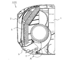
図1〜図4はこの発明の実施の形態1に係る空気調和機を説明するものであって、図1は分解斜視図、図2は断面図、図3はネジ固定部Aの詳細斜視図、図4はネジ固定部Aの断面図を示すものである。
図1〜図4において、室内の空気を空調する空気調和機100の室内ユニットの本体1の前面には意匠パネル2が設置され、意匠パネル2の下方に吹出口9が形成されている。本体1の内部には、室内空気と熱交換(冷却または加熱)する熱交換器5と、室内空気を送風する送風機6と、が配置され、熱交換された空気は、ファンケーシング7に案内された吹出口9を経由して室内に吹き出される。
[Embodiment 1]
1 to 4 illustrate an air conditioner according to
1 to 4, a
意匠パネル2は吹出口9において固定ネジ3によって本体1に固定され、固定ネジ3はネジカバー4によって覆われている。
ファンケーシング7の終端部7aは、側面視で「<状(横V字状に同じ)」に前面に突出し、その下面側に結露発生部8が形成され、結露発生部8の終端から略垂直下方にケーシング垂直部7bが形成されている。そして、ケーシング垂直部7bに固定ネジ3が貫通するケーシング固定用孔または固定用切欠7cが形成されている。
意匠パネル2は、パネル底板2aと、パネル底板2aの前面で略垂直に立ち上がったパネル垂直部2bと、パネル垂直部2bに形成された固定ネジ3が貫通するパネル固定孔2cと、パネル垂直部2bの上縁から前方に庇状に突出したフランジ10と、を有している。
なお、パネル垂直部2b(吹出口9に設けられている)を含む範囲を「ネジ固定部A」と称している。すなわち、ネジ固定部Aは、意匠パネル2のパネル固定孔2cとファンケーシング7のケーシング固定用孔または固定用切欠7cとを貫通する固定ネジ3が、本体1に螺合することによって、固定ネジ3と意匠パネル2とファンケーシング7とが本体1に固定され、さらに、固定ネジ3の前面側にネジカバー4が設置されている。
The
The end portion 7 a of the
The
Note that a range including the panel
次に動作について説明する。
このように構成された空気調和機の本体1においては、電源が投入されると、送風機6が駆動し、室内空気は本体内に吸い込まれて熱交換器5を通過して、ファンケーシング7を通り、意匠パネル2の吹出口9を経由して室内へ吹き出される。
このとき、意匠パネル2は、吹出口9の下部をネジ3で本体1と固定され、見栄えをよくするためネジ3が見えないように意匠パネル2の吹出口9と類似形状のネジカバー4で覆われている。さらに、意匠パネル2のフランジ10をネジ3の頭形状に沿った形状としている。
Next, the operation will be described.
In the
At this time, the
ファンケーシング7の終端に形成された結露発生部8では、熱交換器5により熱交換された冷たく乾燥した空気が室内の暖かい湿った空気と混ざるため結露が発生する。結露発生部8に着露した結露水は、結露発生部8とこれに近接した意匠パネル2のフランジ10との隙間、さらに、パネル垂直部10bとケーシング垂直部7bとの隙間を毛細管現象によって案内され、意匠パネル2のパネル底板7aの結露水回収部2dに流入する(図4において矢印にて示す)。
このため、ネジ固定部Aから本体1の外への結露水の滴下を防ぐことができる。
また、意匠パネル2にフランジ10が設けられているため、ネジ固定部Aの強度アップ(正確には、パネル垂直部2bの剛性向上)を図ることができ、組立時の扱いが容易になっている。
さらに、意匠パネル2のフランジ10をネジ3の頭形状に沿った形状にしているため、固定ネジ3が案内され、ネジ締め作業性が容易になっている。
In the dew
For this reason, dripping of dew condensation water from the screw fixing part A to the outside of the
Further, since the
Furthermore, since the
[実施の形態2]
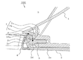
図5はこの発明の実施の形態2に係る空気調和機を説明するものであって、ネジ固定部Aの断面図を示すものである。
前記した実施の形態1では、意匠パネル2の吹出口9に設けられたネジ固定部Aの上部には固定ネジ3の頭形状に沿ったフランジ10を設けているが、図5に示す空気調和機200は、意匠パネル2xのパネル垂直部2bの上縁に、本体1の背面側に向かって下る「下り勾配の傾斜」を設けたフランジ10xを備えている。
すなわち、実施の形態1において説明した空気調和機100は、意匠パネル2の吹き出し口9に設けられたネジ固定部Aの上部に固定ネジ3の頭形状に沿ったフランジ10を設けているが、実施の形態2において説明する空気調和機200は、下り勾配の傾斜を設けたフランジ10xを具備する点において、両者は相違し、その他の部分は同じであるから、同じ部分または相当する部分には同じ符号を付し、一部の説明を省略する。
したがって、意匠パネル2xのフランジ10xは、実施の形態1において説明した空気調和機100のフランジ10より、ファンケーシング7の結露発生部8に近接している。さらに、意匠パネル2xのフランジ10xはネジ3の頭形状に沿った形状に形成されている。
[Embodiment 2]
FIG. 5 illustrates an air conditioner according to
In the first embodiment described above, the
That is, the
Therefore, the
以上のように、意匠パネル2xのフランジ10xは、本体1の背面側に下り勾配の傾斜を設けているので、ファンケーシング7の結露発生部8に着露した結露水は、結露発生部8とこれに近接した意匠パネル2xのフランジ10xとの隙間、さらに、パネル垂直部10bとケーシング垂直部7bとの隙間を毛細管現象によって案内され、意匠パネル2xのパネル底板7aの結露水回収部2dに流入する。
よって、ネジ固定部Aからの結露水の滴下を防ぐことができる。
また、意匠パネル2xにフランジ10xを設けるので、ネジ固定部Aの強度アップ(正確には、パネル垂直部2bの剛性向上)を図ることができ、組立時の扱いが容易になる。
さらに、意匠パネル2xのフランジ10xを固定ネジ3の頭形状に沿った形状に形成しているため、固定ネジ3が案内され、ネジ締め作業性が容易になる。
また、意匠パネル2xのフランジ10xは本体1の背面側に下り勾配の傾斜を設けているので、毛細管現象だけでなく結露水の自重によっても意匠パネル2xの結露水回収部2dに案内されるため、ネジ固定部Aからの結露水の滴下がより確実に防止される。
As described above, since the
Therefore, dripping of condensed water from the screw fixing portion A can be prevented.
Further, since the
Furthermore, since the
Further, since the
[実施の形態3、4]
実施の形態3、4は、前記した実施の形態1、2における空気調和機100、200における結露水が毛細管現象によって案内される径路に親水性を持たせたものである。
すなわち、本発明の実施の形態3に係る空気調和機300(図示しない)は、実施の形態1に示した空気調和機100の意匠パネル2のフランジ10に、例えば吸水シートを貼付して、親水性を持たせたものである(図4参照)。
また、本発明の実施の形態4に係る空気調和機400(図示しない)は、実施の形態2に示した空気調和機200の意匠パネル2xのフランジ10xに、例えば吸水シートを貼付して、親水性を持たせたものである(図5参照)。
[
In the third and fourth embodiments, the path through which the condensed water in the
That is, the air conditioner 300 (not shown) according to the third embodiment of the present invention attaches, for example, a water absorbent sheet to the
In addition, the air conditioner 400 (not shown) according to
以上のように、実施の形態1、2に示す空気調和機30、400は、結露水が案内される径路が親水性を有するため、実施の形態1、2の効果に加え、結露水が毛細管現象によって結露発生部8から結露水回収部2dにより確実に案内される。よって、ネジ固定部Aからの結露水の滴下をより確実に防ぐことができる。
As described above, in the air conditioners 30 and 400 shown in the first and second embodiments, since the path through which the dew condensation water is guided has hydrophilicity, in addition to the effects of the first and second embodiments, the dew condensation water is a capillary tube. Due to the phenomenon, the dew
本発明は以上の構成であるから、室内ユニットからの結露水の滴下を防ぐことができるから、各種空気調和機として広く利用することができる。 Since this invention is the above structure, since it can prevent the dew condensation water from an indoor unit dripping, it can utilize widely as various air conditioners.
1:本体、2:意匠パネル、3:固定ネジ、4:ネジカバー、5:熱交換器、6:送風機、7:ファンケーシング、8:結露発生部、9:吹出口、10:フランジ、100:空気調和機(実施の形態1)、200:空気調和機(実施の形態2)。 DESCRIPTION OF SYMBOLS 1: Main body, 2: Design panel, 3: Fixing screw, 4: Screw cover, 5: Heat exchanger, 6: Blower, 7: Fan casing, 8: Condensation generating part, 9: Air outlet, 10: Flange, 100: Air conditioner (Embodiment 1), 200: Air conditioner (Embodiment 2).
Claims (4)
該本体の前面に設置され、開口した吹出口が形成されている意匠パネルと、
前記本体の内部に設置された、室内空気を冷却する熱交換器と、室内空気を吸引すると共に前記熱交換器において冷却された室内空気を送り出す送風機と、該送風機によって送り出された前記冷却された室内空気を前記吹出口に案内するファンケーシングと、
を、具備する室内ユニットを有する空気調和機であって、
前記ファンケーシングの前面側の突出したケーシング終端部から所定の距離だけ背面寄りの位置に形成された下方に突出するケーシング垂直部が、意匠パネルの前面側の吹出口下部の縁部に形成された上方に突出するパネル垂直部と共に、固定ボルトによって前記本体に固定され、
前記パネル垂直部の上縁に形成されたフランジが、前記固定ボルトの上に覆い被さると共に、前記ケーシング終端部が前記フランジの前面側の終端部よりも前面側に突出することを特徴とする空気調和機。 The body,
A design panel installed on the front surface of the main body and having an open outlet;
A heat exchanger for cooling indoor air, an air blower for sucking indoor air and sending out indoor air cooled in the heat exchanger, and the cooled air sent by the air blower. A fan casing for guiding indoor air to the air outlet;
An air conditioner having an indoor unit comprising:
A vertically extending casing vertical portion formed at a position close to the back surface by a predetermined distance from a protruding casing end portion on the front side of the fan casing is formed at the edge of the lower portion of the blowout port on the front side of the design panel. Along with the panel vertical part protruding upward, it is fixed to the main body by a fixing bolt,
A flange formed on an upper edge of the panel vertical portion covers the fixing bolt, and the casing terminal portion protrudes to the front side from the front side terminal portion of the flange. Harmony machine.
Priority Applications (1)
| Application Number | Priority Date | Filing Date | Title |
|---|---|---|---|
| JP2007060001A JP5057801B2 (en) | 2007-03-09 | 2007-03-09 | Air conditioner |
Applications Claiming Priority (1)
| Application Number | Priority Date | Filing Date | Title |
|---|---|---|---|
| JP2007060001A JP5057801B2 (en) | 2007-03-09 | 2007-03-09 | Air conditioner |
Publications (3)
| Publication Number | Publication Date |
|---|---|
| JP2008224083A JP2008224083A (en) | 2008-09-25 |
| JP2008224083A5 JP2008224083A5 (en) | 2009-08-13 |
| JP5057801B2 true JP5057801B2 (en) | 2012-10-24 |
Family
ID=39842922
Family Applications (1)
| Application Number | Title | Priority Date | Filing Date |
|---|---|---|---|
| JP2007060001A Active JP5057801B2 (en) | 2007-03-09 | 2007-03-09 | Air conditioner |
Country Status (1)
| Country | Link |
|---|---|
| JP (1) | JP5057801B2 (en) |
Families Citing this family (5)
| Publication number | Priority date | Publication date | Assignee | Title |
|---|---|---|---|---|
| JP5370191B2 (en) * | 2010-02-05 | 2013-12-18 | 三菱電機株式会社 | Air conditioner indoor unit |
| CN103307728B (en) * | 2013-05-27 | 2016-03-02 | 广东志高空调有限公司 | A kind of panel construction of wall-hanging air conditioner |
| CN108151282B (en) * | 2018-03-19 | 2023-09-15 | 奥克斯空调股份有限公司 | Anti-condensation structure and air conditioner |
| DE112018008210B4 (en) | 2018-12-17 | 2024-04-04 | Mitsubishi Electric Corporation | Indoor unit for an air conditioner |
| CN114941897A (en) * | 2022-05-25 | 2022-08-26 | 青岛海尔空调电子有限公司 | Humidity adjusting assembly for air conditioner and air conditioner |
Family Cites Families (10)
| Publication number | Priority date | Publication date | Assignee | Title |
|---|---|---|---|---|
| JPS5824115Y2 (en) * | 1979-07-05 | 1983-05-23 | 松下電器産業株式会社 | Air conditioner dew treatment device |
| JPS61170929U (en) * | 1985-04-10 | 1986-10-23 | ||
| JP2854032B2 (en) * | 1989-09-12 | 1999-02-03 | 三洋電機株式会社 | Air conditioner |
| JPH04106332A (en) * | 1990-08-27 | 1992-04-08 | Sanyo Electric Co Ltd | Air conditioner |
| JPH04344032A (en) * | 1991-05-21 | 1992-11-30 | Hitachi Ltd | Air conditioner and prevention of dripping of condensate |
| JPH0763369A (en) * | 1993-08-23 | 1995-03-07 | Sanyo Electric Co Ltd | Opening car for front cover of air conditioner |
| JPH10148349A (en) * | 1996-11-19 | 1998-06-02 | Matsushita Electric Ind Co Ltd | Air flow direction changing device for air conditioner |
| JP3050145B2 (en) * | 1996-11-27 | 2000-06-12 | ダイキン工業株式会社 | Ceiling-mounted air conditioner |
| JPH1186148A (en) * | 1997-08-30 | 1999-03-30 | Okuda Seisakusho:Kk | Burglar alarm for sliding door |
| JP4578351B2 (en) * | 2005-08-12 | 2010-11-10 | 河村電器産業株式会社 | Cabinet frame mounting structure |
-
2007
- 2007-03-09 JP JP2007060001A patent/JP5057801B2/en active Active
Also Published As
| Publication number | Publication date |
|---|---|
| JP2008224083A (en) | 2008-09-25 |
Similar Documents
| Publication | Publication Date | Title |
|---|---|---|
| JP4544364B1 (en) | Air conditioner | |
| JP6268586B2 (en) | Air conditioner | |
| JP5057801B2 (en) | Air conditioner | |
| WO2017134723A1 (en) | Indoor unit for air-conditioner | |
| JP4961979B2 (en) | Air conditioner electrical component unit and air conditioner outdoor unit equipped with the same | |
| JP6405524B2 (en) | Air conditioner | |
| JP6179794B2 (en) | Air conditioner | |
| JP6111947B2 (en) | Air conditioner | |
| JP2007285533A (en) | Indoor unit of air conditioner | |
| JP5410047B2 (en) | Air conditioner | |
| JP2008224083A5 (en) | ||
| JP2007120789A (en) | Indoor unit for air conditioner | |
| JP4391575B1 (en) | Embedded ceiling air conditioner | |
| JP2014196882A (en) | Air conditioner | |
| JP4081681B2 (en) | Indoor unit and air conditioner | |
| JP2010048468A (en) | Air conditioner | |
| JPH1068534A (en) | Air conditioner | |
| JP6155737B2 (en) | Air conditioning indoor unit | |
| CN215337011U (en) | Water guide structure of evaporator, air duct machine and air conditioner | |
| JP2010048470A (en) | Air conditioner | |
| JP6225721B2 (en) | Air conditioner | |
| JP2006084076A (en) | Indoor machine for air conditioner | |
| JP5507160B2 (en) | Wall-mounted air conditioner | |
| KR100701930B1 (en) | Structure of arraying a hose in stand type air-conditioner | |
| JP5260035B2 (en) | Air blowing unit and floor-mounted air conditioner |
Legal Events
| Date | Code | Title | Description |
|---|---|---|---|
| A521 | Request for written amendment filed |
Free format text: JAPANESE INTERMEDIATE CODE: A523 Effective date: 20090630 |
|
| A621 | Written request for application examination |
Free format text: JAPANESE INTERMEDIATE CODE: A621 Effective date: 20090630 |
|
| A977 | Report on retrieval |
Free format text: JAPANESE INTERMEDIATE CODE: A971007 Effective date: 20110520 |
|
| A131 | Notification of reasons for refusal |
Free format text: JAPANESE INTERMEDIATE CODE: A131 Effective date: 20110607 |
|
| A521 | Request for written amendment filed |
Free format text: JAPANESE INTERMEDIATE CODE: A523 Effective date: 20110801 |
|
| A131 | Notification of reasons for refusal |
Free format text: JAPANESE INTERMEDIATE CODE: A131 Effective date: 20120104 |
|
| A521 | Request for written amendment filed |
Free format text: JAPANESE INTERMEDIATE CODE: A523 Effective date: 20120227 |
|
| TRDD | Decision of grant or rejection written | ||
| A01 | Written decision to grant a patent or to grant a registration (utility model) |
Free format text: JAPANESE INTERMEDIATE CODE: A01 Effective date: 20120724 |
|
| A01 | Written decision to grant a patent or to grant a registration (utility model) |
Free format text: JAPANESE INTERMEDIATE CODE: A01 |
|
| A61 | First payment of annual fees (during grant procedure) |
Free format text: JAPANESE INTERMEDIATE CODE: A61 Effective date: 20120731 |
|
| FPAY | Renewal fee payment (event date is renewal date of database) |
Free format text: PAYMENT UNTIL: 20150810 Year of fee payment: 3 |
|
| R150 | Certificate of patent or registration of utility model |
Ref document number: 5057801 Country of ref document: JP Free format text: JAPANESE INTERMEDIATE CODE: R150 Free format text: JAPANESE INTERMEDIATE CODE: R150 |
|
| R250 | Receipt of annual fees |
Free format text: JAPANESE INTERMEDIATE CODE: R250 |
|
| R250 | Receipt of annual fees |
Free format text: JAPANESE INTERMEDIATE CODE: R250 |
|
| R250 | Receipt of annual fees |
Free format text: JAPANESE INTERMEDIATE CODE: R250 |
|
| R250 | Receipt of annual fees |
Free format text: JAPANESE INTERMEDIATE CODE: R250 |
|
| R250 | Receipt of annual fees |
Free format text: JAPANESE INTERMEDIATE CODE: R250 |
|
| R250 | Receipt of annual fees |
Free format text: JAPANESE INTERMEDIATE CODE: R250 |
|
| R250 | Receipt of annual fees |
Free format text: JAPANESE INTERMEDIATE CODE: R250 |
|
| R250 | Receipt of annual fees |
Free format text: JAPANESE INTERMEDIATE CODE: R250 |
|
| R250 | Receipt of annual fees |
Free format text: JAPANESE INTERMEDIATE CODE: R250 |