JP5054698B2 - Hearing aid fitting method and system - Google Patents
Hearing aid fitting method and system Download PDFInfo
- Publication number
- JP5054698B2 JP5054698B2 JP2008535897A JP2008535897A JP5054698B2 JP 5054698 B2 JP5054698 B2 JP 5054698B2 JP 2008535897 A JP2008535897 A JP 2008535897A JP 2008535897 A JP2008535897 A JP 2008535897A JP 5054698 B2 JP5054698 B2 JP 5054698B2
- Authority
- JP
- Japan
- Prior art keywords
- hearing aid
- gain
- vent
- parameter
- wearing
- Prior art date
- Legal status (The legal status is an assumption and is not a legal conclusion. Google has not performed a legal analysis and makes no representation as to the accuracy of the status listed.)
- Expired - Fee Related
Links
Images


Classifications
-
- H—ELECTRICITY
- H04—ELECTRIC COMMUNICATION TECHNIQUE
- H04R—LOUDSPEAKERS, MICROPHONES, GRAMOPHONE PICK-UPS OR LIKE ACOUSTIC ELECTROMECHANICAL TRANSDUCERS; DEAF-AID SETS; PUBLIC ADDRESS SYSTEMS
- H04R25/00—Deaf-aid sets, i.e. electro-acoustic or electro-mechanical hearing aids; Electric tinnitus maskers providing an auditory perception
- H04R25/70—Adaptation of deaf aid to hearing loss, e.g. initial electronic fitting
-
- H—ELECTRICITY
- H04—ELECTRIC COMMUNICATION TECHNIQUE
- H04R—LOUDSPEAKERS, MICROPHONES, GRAMOPHONE PICK-UPS OR LIKE ACOUSTIC ELECTROMECHANICAL TRANSDUCERS; DEAF-AID SETS; PUBLIC ADDRESS SYSTEMS
- H04R2460/00—Details of hearing devices, i.e. of ear- or headphones covered by H04R1/10 or H04R5/033 but not provided for in any of their subgroups, or of hearing aids covered by H04R25/00 but not provided for in any of its subgroups
- H04R2460/11—Aspects relating to vents, e.g. shape, orientation, acoustic properties in ear tips of hearing devices to prevent occlusion
Abstract
Description
この発明は,包括的には補聴器の分野に関し,特に個々の補聴器についての未知の伝達関数(unknown transfer functions)を推定する方法およびシステムに関する。さらにこの発明は,推定されたベント・パラメータ(an estimated vent parameter)を用いて補聴器を調節またはフィッティングする方法およびシステムに関するもので,より詳細には伝送線路理論を用いて実施される測定(計測)(a performed measurement with transmission line theory)をモデリングして補聴器のベスト・フィット音響モデル(the best fit acoustic model)を推定することによって,補聴器ゲインをフィッティング(調節,調整)する,コンピュータ実行方法およびコンピュータ・システムに関する。 The present invention relates generally to the field of hearing aids, and more particularly to a method and system for estimating unknown transfer functions for individual hearing aids. The present invention further relates to a method and system for adjusting or fitting a hearing aid using an estimated vent parameter, and more particularly, measurement (measurement) performed using transmission line theory. A computer-implemented method and computer-aided method for fitting (adjusting, adjusting) a hearing aid gain by modeling a performed measurement with transmission line theory and estimating the best fit acoustic model of the hearing aid About the system.
耳の中または耳の上に取付けることを意図した補聴器が,この技術分野において知られている。 Hearing aids intended to be installed in or on the ear are known in the art.
WO03/034784−A1号には,システムの一部が補聴器ユーザの外耳道に音を伝えることを意図されており,この部分が外耳道にベント(a vent)または通気管(ventilation canal)を提供し,これにより補聴器ユーザをときに不快にさせることで知られる閉塞効果(occulusion effect)の発生を減少させる,そのようなデジタル補聴器システムが記載されている。 In WO 03 / 034784-A1, a part of the system is intended to transmit sound to the hearing instrument user's ear canal, which provides a vent or ventilation canal to the ear canal, Such a digital hearing aid system is described which reduces the occurrence of the occlusion effect known to sometimes make the hearing aid user uncomfortable.
補聴器の音響特性(acoustic properties),すなわち動作ゲイン(actual gain)の決定において,補聴器ユーザの個々の外耳道形状は,通気管の寸法と相互作用する。 In determining the acoustic properties of a hearing aid, i.e., the actual gain, the individual ear canal shape of the hearing aid user interacts with the dimensions of the vent tube.
たとえシール・プラグを備えた補聴器を使用しても,個々の外耳道の形状のために,外耳道壁と補聴器のイヤプラグとの間に漏れ(leakage)が生じ,補聴器の音響特性に影響が生じることがある。このような漏れは,ユーザの個々の外耳道形状に通常適合する,特注のイヤ・プラグやたとえばシリコン製の柔軟性イヤ・プラグを備えた補聴器を使用していても,生じる可能性がある。 Even if a hearing aid with a sealing plug is used, the shape of the individual ear canal can cause leakage between the ear canal wall and the earplug of the hearing aid, affecting the acoustic characteristics of the hearing aid. is there. Such leaks can occur even when using hearing aids with custom-made ear plugs or flexible ear plugs, eg made of silicon, that usually fit the user's individual ear canal geometry.
補聴器のフィッティング(調節,調整)は,通常,オージオロジストによるフィッティング・セッション(fitting session)のときに行われ,このフィッティングでは補聴器ユーザの所定周波数帯域(複数)における聴覚閾値レベル(複数)が測定され,周波数範囲に対する適切な補聴器ゲインが決定される。オージオグラムを記録することによって,聴力損失の周波数依存測定,またはいわゆる聴覚閾値レベル(HTL)(hearing threshold level)を測定(計測)することができる。オージオグラムとは聴力検査(hearing test)のグラフ表示である。オージオグラムの記録では,補聴器ユーザが音を聞取るために必要とされる最低限の音響レベルが,様々な周波数ごとに,各耳に対して示される。この検査において使用される音は,スピーカ(loudspeakers)または補聴器のような装置によって生成されて,聴覚閾値における鼓膜の音圧も測定される。 Hearing aid fitting is usually done during an audiologist's fitting session, which measures the hearing threshold level (s) in a given frequency band (s) of the hearing aid user. , The appropriate hearing aid gain for the frequency range is determined. By recording the audiogram, a frequency dependent measurement of hearing loss, or a so-called hearing threshold level (HTL) (hearing threshold level) can be measured (measured). An audiogram is a graphical representation of a hearing test. In the audiogram recording, the minimum sound level required for the hearing aid user to hear the sound is indicated for each ear at various frequencies. The sound used in this test is generated by a device such as loudspeakers or hearing aids, and the eardrum sound pressure at the hearing threshold is also measured.
その後,補聴器によって提供されるべき必要ゲインが,上記オージオグラムおよび他のフィッティング・ルール(fitting rules)に基づいて算出される。しかしながら,実際に補聴器を使用するときの音圧または耳の中の他の音響特性,および補聴器の実際のゲインに影響を与える漏れ(a leakage)の存在,さらには通気管(ベント)の存在についてさえ,補聴器の実際のゲインの算出(計算)の際に考慮されていない。このように,実際に補聴器を耳に取付けているユーザの個々の外耳道の音響特性に基づいて補聴器ゲインを算出していないことが,現状の補聴器フィッティング手順における問題となっている。 The required gain to be provided by the hearing aid is then calculated based on the audiogram and other fitting rules. However, regarding the sound pressure or other acoustic characteristics of the ear when actually using a hearing aid, and the presence of a leakage that affects the actual gain of the hearing aid, and the presence of a vent. Even the actual gain of the hearing aid is not taken into account. Thus, the problem with the current hearing aid fitting procedure is that the hearing aid gain is not calculated based on the acoustic characteristics of the individual ear canal of the user who actually attaches the hearing aid to the ear.
したがって,聴覚障害者それぞれの外耳道にあるときの補聴器の音響特性を考慮して,補聴器をフィッティングする改良技術が求められている。 Therefore, there is a need for an improved technique for fitting a hearing aid in consideration of the acoustic characteristics of the hearing aid when it is in the ear canal of each hearing impaired person.
今日の補聴器は,個々人の解剖学的差異および個々人の補聴器プラグに関係なく,あらゆる個人をカバーする理想的条件のもとで,ユーザに対してフィッティングがなされている。この理想的条件は,個別のプラグを装着した個々の耳が,平均的な耳を模したカプラに取付けられた標準のイヤプラグと同様に機能すると仮定することによって,得られている。しかしながら,平均的な耳というものは存在せず,たとえ今日におけるフィッティングが所定のゲインについて適正な推定を行うとしても,現実的にはいくつかの矛盾が残る。したがって,この発明は,個々のフィッティングを高精度に実現することができる方法およびシステムを提供することを目的とする。 Today's hearing aids are fitted to users under ideal conditions covering all individuals, regardless of individual anatomical differences and individual hearing aid plugs. This ideal condition is obtained by assuming that individual ears with individual plugs function in the same way as standard earplugs attached to couplers that mimic the average ear. However, there is no average ear, and there are some inconsistencies in reality even if today's fittings make a reasonable estimate for a given gain. Accordingly, an object of the present invention is to provide a method and a system capable of realizing each fitting with high accuracy.
この発明はさらに,補聴器のフィッティング能力,または考えられるあらゆる補聴器特性に関する設定の調整能力を高める方法およびシステムを提供することを目的とする。 It is a further object of the present invention to provide a method and system that enhances the hearing aid's fitting ability or ability to adjust settings for any conceivable hearing aid characteristic.
より詳細には,この発明は,補聴器ユーザの個々の外耳道の形状と補聴器の形状の相互作用を考慮に入れた,補聴器ゲインのフィッティング方法およびシステムを提供することを目的とする。 More particularly, an object of the present invention is to provide a hearing aid gain fitting method and system that takes into account the interaction between the shape of the individual ear canal of the hearing aid user and the shape of the hearing aid.
この発明はさらに,いわゆる装着(現場)オージオグラム(in-situ audiogram)を記録するときに,測定された聴覚閾値を補正することを目的とする。 The invention further aims to correct the measured auditory threshold when recording so-called in-situ audiograms.
この発明はまた,音響環境を考慮に入れた補正聴覚閾値を用いて,補聴器に必要なゲインを算出することを目的とする。 Another object of the present invention is to calculate a gain required for a hearing aid using a corrected auditory threshold value that takes into account the acoustic environment.
この発明の第1の態様によると,装着補聴器(in-situ hearing aid)の音響特性を測定し,多数の所定音響特性(a number of predetermined acoustic properties)と測定音響特性(the measured acoustic property)の間のベスト・フィット(最適にフィッティングしているもの)(the best fit)によって等価補聴器構成(equivalent hearing aid configuration)を推定し,上記推定等価補聴器構成から得られる少なくとも一つの音響特性を決定する,補聴器のフィッティング方法が提供されている。提案の方法は,耳の周囲および/または内部の音響環境を探査し(probing),補聴器の個々の音響効果を最適化するのに必要と考えられる補正を推定することによって,個々のフィッティングを高精度に実現する。この発明の最も顕著で一般的な利点は,上記方法によって個々の装着補聴器に関する未知の音響特性(複数)および伝達関数(複数)の推定が可能になることである。これらの推定された関数(複数)は,フィッティングのため,または他の何らかの補聴器特性の設定の調節のために,使用することができる。 According to a first aspect of the invention, the acoustic characteristics of an in-situ hearing aid are measured and a number of predetermined acoustic properties and the measured acoustic properties are measured. Estimating the equivalent hearing aid configuration by the best fit, and determining at least one acoustic characteristic obtained from the estimated equivalent hearing aid configuration, A method for fitting a hearing aid is provided. The proposed method increases the individual fitting by probing the acoustic environment around and / or inside the ear and estimating the corrections that are considered necessary to optimize the individual acoustic effects of the hearing aid. Realize to accuracy. The most prominent and general advantage of the present invention is that the above method allows estimation of unknown acoustic characteristics and transfer functions for individual worn hearing aids. These estimated functions can be used for fitting or for adjusting the setting of some other hearing aid characteristic.
この発明の第2の態様によると,補聴器ゲインのフィッティング方法が提供される。この方法は,少なくとも一つの周波数帯域について,装着補聴器のループ・ゲインを測定し,多数の所定ループ・ゲインと測定ループ・ゲインとの間のベスト・フィットを提供するベント・パラメータを有効ベント・パラメータとして決定することによって,補聴器の有効ベント・パラメータ(effective vent parameter)を推定し,上記有効ベント・パラメータに基づいて補正ゲインを算出し,上記補正ゲインによって上記補聴器ゲインを補正するものである。この態様によると,装着伝達関数(装着時の伝達関数)の測定値(the measured measurement of the in-situ transfer function)はループ・ゲインである。上記ループ・ゲインは,フィードバック検査(feedback test)を用いて測定してもよい。所定の補聴器伝達関数の蓄積(pool)は,測定される装着伝達関数,ベント効果および直接伝達ゲインを反復する,任意のシミュレートされたフィードバック検査(any simulated feedback test)となる。たとえば,さまざまな補聴器構成(different hearing aid configurations)は,この態様にしたがって,さまざまなベント・パラメータ(複数)によって,表わされる。 According to a second aspect of the present invention, a method for fitting a hearing aid gain is provided. This method measures the loop gain of a wearable hearing aid for at least one frequency band and enables the vent parameter to provide a best fit between a number of predetermined loop gains and the measured loop gain. As a result, the effective vent parameter of the hearing aid is estimated, a correction gain is calculated based on the effective vent parameter, and the hearing aid gain is corrected by the correction gain. According to this aspect, the measured measurement of the in-situ transfer function is a loop gain. The loop gain may be measured using a feedback test. The pool of a given hearing aid transfer function is an arbitrary simulated feedback test that repeats the measured wear transfer function, vent effect and direct transfer gain. For example, different hearing aid configurations are represented by different vent parameters according to this embodiment.
上記所定ループ・ゲインは,モデル化データ(modeled data),実験データ,推定値,またはこれらの任意の組合わせに基づくものであってもよい。所定のループ・ゲイン(複数),対応するベント効果(複数)(vent effects)および直接伝達ゲイン(複数)(direct transmission gain)は,計算の高速化のために,テーブル(複数)(tables)に格納させておくことができる。 The predetermined loop gain may be based on modeled data, experimental data, estimates, or any combination thereof. A given loop gain (s), corresponding vent effects (s) and direct transmission gain (s) are stored in tables for faster calculation. Can be stored.
この発明の別の態様によると,補聴器ゲインをフィッティングする,補聴器に接続可能なコンピュータ・システムが提供されている。このコンピュータ・システムは,一般にフィッティングのときに用いられる。フィッティングすべき補聴器は,補聴器ユーザの外耳道に挿入されて,フィッティング手順を実行する実行可能なプログラム・コードを備えた上記コンピュータ・システムに接続される。上記コンピュータ・システム上で実行される上記プログラム・コードは,装着補聴器のループ・ゲインを測定(計測)するプログラム部分,多数の所定ループ・ゲインと測定ループ・ゲインとの間のベスト・フィットを提供するベント・パラメータを有効ベント・パラメータとして決定することによって,上記補聴器の有効ベント・パラメータを推定するプログラム部分,上記有効ベント・パラメータに基づいて補正ゲインを算出するプログラム部分,上記補正ゲインによって上記補聴器ゲインを補正するプログラム部分を含む。このフィッティング手順は,少なくとも一つの関連周波数帯域について実行される。 In accordance with another aspect of the invention, a computer system is provided that can be connected to a hearing aid to fit the hearing aid gain. This computer system is generally used for fitting. The hearing aid to be fitted is connected to the computer system with executable program code that is inserted into the ear canal of the hearing aid user and performs the fitting procedure. The program code executed on the computer system provides a program part that measures (measures) the loop gain of the hearing aid, and provides a best fit between a number of predetermined loop gains and the measured loop gain. Determining a vent parameter to be used as an effective vent parameter, a program part for estimating the effective vent parameter of the hearing aid, a program part for calculating a correction gain based on the effective vent parameter, and the hearing aid based on the correction gain. Includes a program part to correct the gain. This fitting procedure is performed for at least one relevant frequency band.
この発明にしたがう方法およびコンピュータ・システムによると,一の周波数帯域における推定有効ベント・パラメータの音響特性を考慮に入れたフィッティング手順を提供することができ,未知のベント効果の手段によって(by means of a vent effect that would be otherwise unknown),決定された補聴器ゲインを補正することができる。 According to the method and the computer system according to the present invention, it is possible to provide a fitting procedure that takes into account the acoustic characteristics of the estimated effective vent parameter in one frequency band, by means of an unknown vent effect (by means of a vent effect that would be otherwise unknown), the determined hearing aid gain can be corrected.
したがって,存在し得るベントを含む漏れ経路を有する補聴器のような音響システムの伝達関数の単一測定値(a single measurement)と,レシーバ・タイプ,音響管(sound canal)の寸法,外耳道サイズ,挿入深さ,中耳特性,ベントの長さ,およびベント開口と補聴器マイクロフォン間の距離などの装着補聴器システムの音響特性に関する多くの条件とに基づいて,この発明にしたがう方法およびシステムは,伝送線路理論を使用して,多数のシミュレートされた装着補聴器の中から,ユーザによって装着されている実際の装着補聴器システムに最も類似した一つを選択する。測定(measurement)とシミュレーション(simulation)との間のベスト・フィットが得られるように一または複数のパラメータが変更される伝送線路理論を用いて実施される測定のモデリングによる,装着補聴器のベスト・フィット音響モデルの推定(the estimation of the best fit acoustic model)に基づいて,全体的なベスト・フィット音響システムが明らかにされ,その結果,補聴器の任意の伝達関数の算出が可能になる。上記伝達関数は,初期補聴器ゲインを補正する補正ゲインの算出に用いられる有効ベント・パラメータを提供する。補正された補聴器ゲインは,補聴器の推定されたベスト・フィット音響モデルに必要なゲインを提供するゲイン値となる。 Therefore, a single measurement of the transfer function of an acoustic system such as a hearing aid with a leak path that may contain vents, receiver type, sound canal dimensions, ear canal size, insertion Based on a number of conditions regarding the acoustic characteristics of a worn hearing aid system, such as depth, middle ear characteristics, vent length, and distance between vent opening and hearing aid microphone, the method and system according to the present invention is based on transmission line theory. Is used to select one of a number of simulated worn hearing aids that is most similar to the actual worn hearing aid system worn by the user. Wearable hearing aid best fit by modeling measurements performed using transmission line theory where one or more parameters are changed to obtain the best fit between measurement and simulation Based on the estimation of the best fit acoustic model, the overall best fit acoustic system is revealed, so that any transfer function of the hearing aid can be calculated. The transfer function provides an effective vent parameter that is used to calculate a correction gain that corrects the initial hearing aid gain. The corrected hearing aid gain is a gain value that provides the gain required for the estimated best fit acoustic model of the hearing aid.
この発明のまた別の態様によると,補聴器ゲインのフィッティング方法が提供されている。この方法は,少なくとも一つの周波数帯域について実行されるものであり,補聴器ユーザの外耳道内における補聴器のループ・ゲインを測定し,モデル化ループ・ゲインと測定ループ・ゲインとの間のベスト・フィットをもたらすベント・パラメータを決定することによって,上記補聴器の有効ベント・パラメータを推定し,推定された有効ベント・パラメータに基づいてベント効果を決定し,決定されたベント効果の手段によって補正補聴器ゲインを提供するものである。 According to yet another aspect of the invention, a method for fitting a hearing aid gain is provided. This method is performed for at least one frequency band and measures the hearing instrument loop gain in the hearing instrument user's external ear canal to determine the best fit between the modeled loop gain and the measured loop gain. Estimate the effective vent parameter of the hearing aid by determining the resulting vent parameter, determine the vent effect based on the estimated effective vent parameter, and provide a corrected hearing aid gain by means of the determined vent effect To do.
この発明のまた別の態様によると,補聴器ゲインをフィッティングする,補聴器に接続可能なコンピュータ・システムが提供されている。このコンピュータ・システムは,一般にフィッティングのときに用いられる。フィッティングすべき補聴器は聴覚障害者の外耳道に挿入され,さらにフィッティング手順を実行する実行可能なプログラム・コードを有する上記コンピュータ・システムに接続される。上記コンピュータ・システム上で実行される上記プログラム・コードは,補聴器ユーザの外耳道内の補聴器のループ・ゲインを測定するプログラム部分,モデル化ループ・ゲインと測定ループ・ゲインとの間のベスト・フィットをもたらすベント・パラメータを決定することによって,補聴器の有効ベント・パラメータを推定するプログラム部分,推定有効ベント・パラメータに基づいてベント効果値を決定するプログラム部分,決定されたベント効果によって補正補聴器ゲインを提供するプログラム部分を含む。このフィッティング手順も,少なくとも一つの関連周波数帯域について実行される。 In accordance with yet another aspect of the present invention, a computer system connectable to a hearing aid for fitting a hearing aid gain is provided. This computer system is generally used for fitting. The hearing aid to be fitted is inserted into the ear canal of a hearing impaired person and connected to the computer system having executable program code for performing the fitting procedure. The program code executed on the computer system is the program part that measures the loop gain of the hearing aid in the ear canal of the hearing aid user, the best fit between the modeled loop gain and the measured loop gain. By determining the resulting vent parameter, the program part that estimates the effective vent parameter of the hearing aid, the program part that determines the vent effect value based on the estimated effective vent parameter, and the corrected hearing aid gain is provided by the determined vent effect Program part to be included. This fitting procedure is also performed for at least one associated frequency band.
この発明のさらなる態様によると,上記ベント・パラメータは,ベント直径によって十分に規定(定義)されるが(defined),さらなる態様では,ベント長さ,ベント・インダクタンス,ベント容積,またはベント形状もしくは漏れについて他の数学的組合わせ(other mathematical combinations of the vent geometry or leak)によって,表すことができる。 According to a further aspect of the invention, the vent parameter is well defined by the vent diameter, but in a further aspect, the vent length, vent inductance, vent volume, or vent shape or leakage. Can be represented by other mathematical combinations of the vent geometry or leak.
また,補聴器ゲインの補正が,聴覚閾値から補聴器ゲインを算出する規定のフィッティング・ルール(the prescribed fitting rule)に依存しないことは,さらなる利点である。 It is a further advantage that correction of the hearing aid gain does not depend on a prescribed fitting rule that calculates the hearing aid gain from the hearing threshold.
また,この発明が,耳甲介密着型プラグから耳に挿入される音響管に及ぶ任意のタイプのイヤプラグまたはイヤーシェルを備えた,BTE,ITE,CICを含む全ての既知のタイプの補聴器に適用できることが,さらなる利点である。 The invention also applies to all known types of hearing aids, including BTE, ITE, CIC, with any type of earplug or earshell extending from the concha close-contact plug to the acoustic tube inserted into the ear. What can be done is a further advantage.
さらなる利点は,個々の物理的なベント・サイズ,漏れ量,挿入深さ,外耳道サイズ等の特定の知識がなくても,ベント効果および直接伝達ゲインを評価かつ推定することができることである。これらのベント効果および直接伝達ゲインなどのゲイン関数は測定され,さもなければ2つの異なる音源および2つの異なるイヤプラグ(開放および閉鎖ベント)を含む4つの音圧測定が要求される。 A further advantage is that the venting effect and direct transfer gain can be evaluated and estimated without specific knowledge of individual physical vent size, leak rate, insertion depth, ear canal size, etc. Gain functions such as these vent effects and direct transfer gains are measured, otherwise four sound pressure measurements are required, including two different sound sources and two different earplugs (open and closed vents).
この発明にしたがう方法が,物理的ベント・サイズを用いてベントをモデル化することによって得られるよりも,より正確な推定ベント効果を提供することが,さらなる利点である。これは,たとえば外耳道形状における差異が,フィードバック検査等において測定される伝達関数,ひいては有効ベント・パラメータに,反映されるためである。 It is a further advantage that the method according to the invention provides a more accurate estimated venting effect than can be obtained by modeling the vent using physical vent sizes. This is because, for example, a difference in the external auditory canal shape is reflected in a transfer function measured in a feedback test or the like, and thus in an effective vent parameter.
プラグと耳道との間の非制御リーク(制御されていない漏れ)(uncontrolled leakage)をクリニックにおいて判断するのはとても難しい。この発明の別の利点は,シミュレートされたベント・パラメータを最適化するときに,音響的におおよそベントと同様に作用する任意の漏れが,有効パラメータ中に含まれることである。たとえば,漏れの存在によって有効ベントが短くまたは広くされよう(shorter or wider)。このことは,補聴器をユーザに対してフィッティングするときに,この発明が非制御リークを考慮していることを意味する。 It is very difficult to determine at the clinic any uncontrolled leakage between the plug and the ear canal. Another advantage of the present invention is that, when optimizing simulated vent parameters, any leakage that acts acoustically roughly like a vent is included in the effective parameters. For example, the presence of a leak may make the effective vent shorter or wider. This means that the present invention allows for uncontrolled leaks when fitting a hearing aid to the user.
ベント効果と直接音伝達を考慮すると(considering the vent effect and the direct sound transmission),ベント直径,ベント長さ,外耳道への挿入深さ,および外耳道容積等のパラメータは同様の作用(similar influence)を有しており,換言すれば,これらのパラメータはベント効果の遮断周波数を変える。したがって,これらのいずれのパラメータも,原則的にベント・パラメータとして使用することができる。しかしながら,ベント直径が最も重要な影響を有しており,かつ最も直観的に使用されるので,一実施形態では,このパラメータをベント・パラメータとして使用するのが好ましい。 Considering the vent effect and direct sound transmission, parameters such as vent diameter, vent length, depth of insertion into the ear canal, and volume of the ear canal have similar effects. In other words, these parameters change the cutoff frequency of the vent effect. Therefore, any of these parameters can be used as a vent parameter in principle. However, in one embodiment it is preferred to use this parameter as the vent parameter since the vent diameter has the most important effect and is used most intuitively.
一実施形態では,ベント直径をベント・パラメータとして使用すると,たとえ漏れが存在しなくても,物理的なベント直径と等価直径との間の差異を含む可能性がある。それにもかかわらず,装着補聴器の推定ベント効果は,シミュレートされた耳の仮定形状に関わらず,ほぼ同一である。これは,測定ループ・ゲインとシミュレートされたループ・ゲインとの間のベスト・フィットが,測定ベント効果とシミュレートされたベント効果との間のベスト・フィットと同等になるという事実によるものである。したがって,装着補聴器の物理的パラメータとシミュレートされた音響システムの仮定パラメータとの間に起こり得る矛盾は,少なくとも部分的には,可変ベント・パラメータで説明される。 In one embodiment, using the vent diameter as the vent parameter may include a difference between the physical vent diameter and the equivalent diameter, even if there is no leak. Nevertheless, the estimated venting effect of a worn hearing aid is almost the same regardless of the simulated assumed ear shape. This is due to the fact that the best fit between the measured loop gain and the simulated loop gain is equivalent to the best fit between the measured vent effect and the simulated vent effect. is there. Thus, possible discrepancies between the physical parameters of the wearable hearing aid and the assumed parameters of the simulated acoustic system are explained, at least in part, by the variable vent parameter.
フィッティングにおけるベント補正の適用は,注文されるイヤプラグまたはシェルのうち,ベントを有していないものは数パーセントだけであるという事実があるため,妥当である。換言すると,注文されたイヤプラグまたはシェルの大多数がベント(ベンティングとも呼ばれる)を有しているので,この発明は大多数の補聴器ユーザに対する,より正確なフィッティングを可能にし,したがって,この発明は広範囲の聴覚障害者の聴力向上に的確に貢献することができる。 The application of vent compensation in fitting is reasonable due to the fact that only a few percent of the earplugs or shells ordered do not have a vent. In other words, since the majority of ordered earplugs or shells have vents (also called venting), the present invention allows for a more accurate fitting for the majority of hearing aid users, and therefore the present invention It is possible to accurately contribute to the hearing improvement of a wide range of hearing impaired people.
この発明のまた別の態様によると,上記方法はさらに,装着補聴器を複数の音響要素からなる音響システムとして規定することによって,モデル化伝達関数を算出するステップを備えている。 According to another aspect of the invention, the method further comprises the step of calculating a modeled transfer function by defining the worn hearing aid as an acoustic system comprising a plurality of acoustic elements.
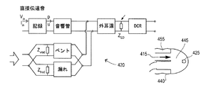
この態様の特定の実施形態によると,上記方法は,周波数依存伝送マトリクス(frequency dependent transmission matrices)によって音響システムの要素を表すことで,外耳道内の補聴器を規定する上記音響システムをモデル化することによって,モデル化ループ・ゲインをシミュレーションし,上記伝送マトリクスに上記音響システムを規定する単一伝送マトリクス(a single transmission matrix)を乗じ,上記単一伝送マトリクスを用いて上記音響システムについて少なくとも一つの伝達関数を算出するものである。上記音響システムは,振幅補正フィルタ,デジタル・アナログ変換器(DAC),補聴器レシーバ,音響管,外耳道,鼓膜,通気管(ベント),およびベント出口から補聴器マイクロフォンへの放射,ならびにこれらの各音響特性を含むことができる。 According to a particular embodiment of this aspect, the method comprises modeling the acoustic system defining a hearing aid in the ear canal by representing the elements of the acoustic system by means of frequency dependent transmission matrices. , Simulate the modeling loop gain, multiply the transmission matrix by a single transmission matrix defining the acoustic system, and use the single transmission matrix to at least one transfer function for the acoustic system. Is calculated. The acoustic system includes an amplitude correction filter, a digital-to-analog converter (DAC), a hearing aid receiver, an acoustic tube, an ear canal, an eardrum, a vent tube (vent), and a vent outlet to a hearing aid microphone, and their respective acoustic characteristics. Can be included.
さらなる態様によると,この発明の方法およびシステムは,補聴器ユーザの少なくとも一つの聴覚閾値レベル(HTL)を測定するステップを含む。このような測定は,周波数依存聴力損失記録として,種々の周波数についてHTLを記録することによって行われる。聴覚閾値レベルをユーザの耳の中の補聴器で直接測定する場合,オージオグラムは装着オージオグラム,または装着フィッティング(in-situ audiogram, or in-situ fitting)とも呼ばれる。装着フィッティングは,補聴器が現実的な音響条件のもとでフィッティングされるという利点を有しているので,補聴器が日常の使用でどのように機能することになるかをイメージしやすくすることができる。しかしながら,装着オージオグラムも,例えばベント直径等の有効ベント・パラメータに基づくベント効果を考慮に入れていないので,装着オージオグラムもまた,ベント効果を補正する必要がある。したがって,この発明の一態様では,有効ベント・パラメータに基づいて上記装着オージオグラムを補正する方法およびシステムが提供される。漏れ経路を有する音響システムの伝達関数を測定し,種々のベント・パラメータに関する伝達関数をシミュレートすることによってベスト・フィット有効ベント・パラメータを決定し,上記有効ベント・パラメータを用いて補正ゲインを算出し,上記補正ゲインを用いて上記装着オージオグラムを補正する。 According to a further aspect, the method and system of the present invention includes measuring at least one hearing threshold level (HTL) of a hearing aid user. Such measurements are made by recording HTL for various frequencies as frequency dependent hearing loss records. When the auditory threshold level is measured directly with a hearing aid in the user's ear, the audiogram is also referred to as an in-situ audiogram, or in-situ fitting. Wearing fittings have the advantage that the hearing aid is fitted under realistic acoustic conditions, making it easier to visualize how the hearing aid will function in everyday use . However, since the wearing audiogram does not take into account the venting effect based on the effective vent parameters such as the vent diameter, the wearing audiogram also needs to correct the venting effect. Accordingly, in one aspect of the present invention, a method and system for correcting the wearing audiogram based on effective vent parameters is provided. Measure the transfer function of an acoustic system with a leakage path, determine the best-fit effective vent parameter by simulating the transfer function for various vent parameters, and calculate the correction gain using the effective vent parameter Then, the mounted audiogram is corrected using the correction gain.
別の態様によると,ユーザの補聴器に関する補正補聴器ゲインは,ユーザの測定された聴覚閾値レベルから補聴器ゲインを得,その後推定有効ベント直径にしたがうベント効果を考慮に入れて,補聴器が耳に取り付けられたときのゲインをもたらすベント効果値を加算することによって上記補聴器ゲインを補正して算出される。通常,ベントはレシーバの出口から伝達された音声信号を減衰してマイクロフォンの入口に戻すので,ベント効果値は負のゲイン量である。 According to another aspect, the corrected hearing aid gain for the user's hearing aid is derived from the user's measured hearing threshold level, and then the hearing aid is attached to the ear taking into account the venting effect according to the estimated effective vent diameter. It is calculated by correcting the hearing aid gain by adding the vent effect value that gives the gain at the time. Normally, the vent attenuates the audio signal transmitted from the receiver outlet and returns it to the microphone inlet, so the vent effect value is a negative gain amount.
別の態様によると,この発明にしたがう方法およびシステムはさらに,推定有効ベント・パラメータに基づく周波数依存直接音伝達(a frequency dependent direst sound transmission)の決定と,この決定された直接音伝達によって補正された補聴器ゲインの提供とを行う。 According to another aspect, the method and system according to the invention is further corrected by a determination of a frequency dependent direst sound transmission based on the estimated effective vent parameter and the determined direct sound transmission. Provide hearing aid gain.
この発明の別の態様によると,伝送線路理論を用いて実施される測定をモデリングすることによって装着補聴器のベスト・フィット音響モデルを推定する方法およびシステムが提供され,一または複数のパラメータが,測定とシミュレーションとの間のベスト・フィットをもたらすように変更される。そうすることにより,全体的なベスト・フィット音響システムが明らかになり,補聴器の任意の伝達関数の算出が可能になる。 In accordance with another aspect of the present invention, a method and system for estimating a best-fit acoustic model of a wearable hearing aid by modeling measurements performed using transmission line theory is provided, wherein one or more parameters are measured And modified to provide the best fit between simulation and simulation. By doing so, the overall best-fit acoustic system is revealed and it is possible to calculate any transfer function of the hearing aid.
さらなる態様では,この発明は請求項19および20に記載のコンピュータ・プログラムおよびコンピュータ・プログラム製品を提供する。
In a further aspect, the present invention provides a computer program and a computer program product according to
また別の態様では,この発明は請求項21および22に記載の補聴器をフィッティングするシステムおよび補聴器を提供する。 In yet another aspect, the present invention provides a hearing aid fitting system and hearing aid according to claims 21 and 22.
この発明のさらなる特定の変形例は,さらなる従属請求項で規定される。 Further specific variants of the invention are defined in the further dependent claims.
この発明の他の態様および利点は,例としてこの発明の原則を例示する添付図面と関連させた,以下の詳細な説明からより明らかになるであろう。 Other aspects and advantages of the present invention will become more apparent from the following detailed description, taken in conjunction with the accompanying drawings, illustrating by way of example the principles of the invention.
この発明は,以下の詳細な説明を,同一符号が同一の構造要素を表す添付図面と併せることによって,容易に理解されよう。 The present invention will be readily understood by the following detailed description in conjunction with the accompanying drawings, in which the same reference numerals represent the same structural elements.
この発明の説明と関連して使用される用語を定義しておく。 Terms used in connection with the description of the present invention are defined.
漏れ経路(the leakage path)は,音響管出口の面から耳の外側まで(またはその逆)の全音響経路(the complete acoustic path)として定義される。上記漏れ経路は,制御される漏れ(被制御リーク)(a controlled leak)(たとえば,ベント)と,外耳道とプラグとの間の制御されない漏れ(非制御リーク)(an uncontrolled leak)を含む。 The leakage path is defined as the complete acoustic path from the acoustic tube exit face to the outside of the ear (or vice versa). The leakage path includes a controlled leak (eg, a vent) and an uncontrolled leak between the ear canal and the plug.
音響システム(the acoustic system)は,音が伝播することができ,一般的に音響発生器から始まって音または振動センサで終わる,一連の音響要素(the series of acoustic elements)として定義される。 The acoustic system is defined as the series of acoustic elements through which sound can propagate and generally begins with an acoustic generator and ends with a sound or vibration sensor.
音響要素(the acoustic element)は,音響特性が同一であるブロック状要素(block-wise elements)として定義される。音響要素は,レシーバのような音響発生器(sound generators),チューブ,通気管または外耳道のようなサウンド・メディエータ(sound mediators),中耳のような集中インピーダンス(lumped impedances),および放射インピーダンス(radiation impedance),その他のものを含む。それぞれの要素は,2×2周波数依存伝送マトリクス(2x2 frequency transmission matrix)によって,数学的に表される。 The acoustic element is defined as a block-wise element with the same acoustic characteristics. The acoustic elements include sound generators such as receivers, sound mediators such as tubes, vents or ear canals, lumped impedances such as the middle ear, and radiation impedances. impedance), including others. Each element is represented mathematically by a 2 × 2 frequency transmission matrix.
伝送線路理論(transmission line theory)は,円筒状チューブまたはレシーバのような音響要素によって音響システムの全体を記述する数学的方法である。伝送線路理論では,生じうる分岐(possible branches)が考慮されて,音源からセンサに至る音響経路に沿う伝送マトリクス(the transmission matrices)を乗算することによって,一の場所から他の場所に至る伝達関数が算出される。その結果得られる全体の伝送マトリクスは,音響システムの終端インピーダンス(the last impedance)(たとえば,鼓膜または放射インピーダンス)において終端し,音響システム全体を記述する。 Transmission line theory is a mathematical method that describes an entire acoustic system by acoustic elements such as cylindrical tubes or receivers. Transmission line theory considers possible branches and multiplies the transmission matrices along the acoustic path from the sound source to the sensor to multiply the transfer function from one place to another. Is calculated. The resulting total transmission matrix terminates at the last impedance of the acoustic system (eg, eardrum or radiated impedance) and describes the entire acoustic system.
伝達関数(the transfer function)は,音響システムに対する入力の周波数スペクトルと,音響システムの所定の場所において測定される出力信号の比として定義される。入力および出力信号は,いずれも電気的,機械的または音響的なものである。伝達関数は,全伝送マトリクス(the total transmission matrix)および終端インピーダンス(the termination impedance)から算出される。音響システムには,制限のない数の種々の伝達関数が存在し得る。 The transfer function is defined as the ratio of the input frequency spectrum to the acoustic system and the output signal measured at a given location of the acoustic system. Input and output signals are all electrical, mechanical or acoustic. The transfer function is calculated from the total transmission matrix and the termination impedance. There can be an unlimited number of different transfer functions in an acoustic system.
有効ベント・パラメータ(the effective vent parameter)は,あらゆる被制御リークおよび/または非制御リーク(any controlled and/or uncontrolled leakage)の記述に用いられる任意のパラメータによって,表わされる。有効ベント・パラメータは,任意形状のベントの一寸法,たとえば円筒状ベントのベント直径,矩形状ベントのベント高さまたは幅,ベント長さ,またはベント容積もしくはベント・インダクタンスなどの寸法の組合わせ(combinations of the dimensions such as vent volume or vent inductance, etc),その他によって,定義される。このパラメータは,補聴器の実際の通気管(the actual ventilation canal)と,外耳道壁と補聴器のイヤプラグとの間の漏れとの結合力(the jointed forces)とほぼ同一の音響特性を提供するように,決定される。 The effective vent parameter is represented by any parameter used to describe any controlled and / or uncontrolled leakage. Effective vent parameters are a combination of dimensions of any shape of vent, such as the vent diameter of a cylindrical vent, vent height or width of a rectangular vent, vent length, or vent volume or vent inductance ( defined by the combinations of the dimensions such as vent volume or vent inductance, etc). This parameter provides an acoustic characteristic that is approximately the same as the jointed forces of the actual ventilation canal of the hearing aid and the leakage between the ear canal wall and the hearing aid earplug, It is determined.
ベント直径は,ベント長,挿入深さ,および残外耳道容積(the residual ear canal volume)と,ベント効果および直接音について(on the vent effect and the direct sound)同様の効果を有しており,かつ最も直感的に使用することができるので,ベント直径をベント・パラメータとして使用するのが好ましい。 The vent diameter has similar effects on the vent length, insertion depth, and the residual ear canal volume, and on the vent effect and the direct sound, and The vent diameter is preferably used as the vent parameter since it can be used most intuitively.
ベント効果(the vent effect)は鼓膜における音圧として定義され,補聴器レシーバ,ならびに所定のベント直径および長さを有するイヤプラグをそれぞれ装着した耳に関して密閉された外耳道(a sealed ear canal)によって生じる。ベント効果はシミュレーションして,たとえば特定の可能なベント直径のゲイン値(利得値)のテーブルを作成することができる。ベント効果は各周波数のゲイン値として表すことができ,さらに補聴器において使用する任意の数の周波数帯域について算出することができる。 The vent effect is defined as the sound pressure in the eardrum and is caused by a hearing ear receiver and a sealed ear canal with respect to the ears each fitted with an earplug having a predetermined vent diameter and length. The vent effect can be simulated to create, for example, a table of gain values (gain values) for specific possible vent diameters. The vent effect can be expressed as a gain value for each frequency, and can be calculated for any number of frequency bands used in the hearing aid.
直接音伝達(direct sound transmission)は鼓膜における音圧として定義することができ,同一の音源によって生じる外部ベント開口における音圧に関して耳の外側の音源によって生じる。直接音伝達の値(単数または複数)(value or values)は直接伝達ゲイン(direct transmission gain)とも呼ばれる。さらに,直接伝達ゲイン(direct transmission gain)も,音響システムをモデリングすることによってシミュレーションすることができる。以下では,直接伝達ゲインという用語を用いる場合,補聴器ゲインを補正する伝達関数を表す。 Direct sound transmission can be defined as the sound pressure in the eardrum and is caused by a sound source outside the ear with respect to the sound pressure at the external vent opening caused by the same sound source. The value or values of direct sound transmission (value or values) is also called direct transmission gain. In addition, direct transmission gain can also be simulated by modeling the acoustic system. In the following, when the term direct transfer gain is used, it represents the transfer function that corrects the hearing aid gain.
ループ・ゲイン(loop gain)(ループ利得)は,漏れ経路(leakage path)を含む音響システムを通して伝達される,音の装着測定値(in-situ measurement of sound)を表す。ループ・ゲインはいわゆるフィードバック検査によって測定され,通常は最大補聴器ゲイン(maximum hearing aid gain)を推定するフィッティング・ルーチンにおいて,日常的に行われる。したがって,この発明による方法はさらなる操作や測定を必要としない(not require any additional manoeuvres or measurements)という利点があり,この発明による方法およびシステムが提供するフィッティング手順において用いられる有効ベント・パラメータを,的確に推定することができる。 Loop gain (loop gain) represents an in-situ measurement of sound transmitted through an acoustic system including a leakage path. The loop gain is measured by a so-called feedback test and is usually done routinely in a fitting routine that estimates the maximum hearing aid gain. Therefore, the method according to the present invention has the advantage of not requiring any additional manoeuvres or measurements, and the effective vent parameters used in the fitting procedure provided by the method and system according to the present invention can be accurately determined. Can be estimated.
補聴器パラメータ(複数)(hearing aid parameters)は,補聴器ゲイン,周波数帯域数,振幅補正フィルタなど,補聴器の様々な特性(any feature)を定義するパラメータ(複数)である。この特性には,フィードバック除去,ノイズ低減,圧縮等が含まれる。 The hearing aid parameters are parameters that define various features of the hearing aid, such as hearing aid gain, number of frequency bands, amplitude correction filter, and the like. This characteristic includes feedback removal, noise reduction, compression, and the like.
物理的補聴器構成(構造)(physical hearing aid configuration)は,レシーバのタイプ,チューブ構成,外耳道,鼓膜,ベント等を含む,耳に対する音響結合の寸法(dimensions of the acoustic coupling to the ear)とともに,シグマ・デルタ変換器,フィルタ等を含む,補聴器特性の電気的構成を定義する。 The physical hearing aid configuration is the sigma along with the dimensions of the acoustic coupling to the ear, including the receiver type, tube configuration, ear canal, eardrum, vent, etc. • Define the electrical configuration of hearing aid characteristics, including delta converters, filters, etc.
音響特性または伝達関数という用語は,未知の個々の補聴器の特性を定義するためにも用いられ,この特性はフィッティングのためまたは他の補聴器特性の設定を調節するために用いられる。音響特性または伝達関数の例としては,ループ・ゲイン,または他の何らかのフィードバック測定結果が挙げられる。 The term acoustic characteristic or transfer function is also used to define the characteristics of an unknown individual hearing aid, which is used for fitting or to adjust the setting of other hearing aid characteristics. Examples of acoustic properties or transfer functions include loop gain or some other feedback measurement result.
等価補聴器構成(equivalent hearing aid configuration)とは,多数の音響特性と,それぞれ測定された音響特性との間のベスト・フィット(最適合)(best fit)をもたらす構成である。 An equivalent hearing aid configuration is a configuration that provides a best fit between a number of acoustic characteristics and each measured acoustic characteristic.
以下,この発明の広範囲な態様を,特定の実施形態を参照して説明する。任意のユーザが装着している装着補聴器の測定が実行され,かつ補聴器伝達関数の所定のトライアルの蓄積(pool of predetermined trials)と比較される方法に関する。所定の蓄積(predetermined pool)には,可能な物理的補聴器構成のいくつかを具現化する,多数の所定伝達関数の組(a number of sets of predetermined transfer functions)が含まれる。これらの種々の所定伝達関数の一つは,測定された装着補聴器の伝達関数と同様である。測定された装着補聴器の伝達関数と,対応する所定伝達関数のそれぞれの誤差(error)が算出され,最小誤差をベスト・フィットと定義する(the least error defines the best fit)。このベスト・フィットは,特定の物理的補聴器構成を表し,これに対して任意の他の伝達関数を決定することができる。このようにすることによって,装着補聴器のあらゆる伝達関数(any transfer function)を,たった一つの伝達関数の測定値(measurement of only one transfer function)から推定することができる。 The broad aspects of this invention are described below with reference to specific embodiments. The present invention relates to a method in which a wearable hearing aid worn by any user is measured and compared to a pool of predetermined trials of the hearing aid transfer function. The predetermined pool includes a number of sets of predetermined transfer functions that embody some of the possible physical hearing aid configurations. One of these various predetermined transfer functions is similar to the measured transfer function of a worn hearing aid. Each error of the measured wearing hearing aid transfer function and the corresponding predetermined transfer function is calculated, and the minimum error is defined as the best fit. This best fit represents a specific physical hearing aid configuration, for which any other transfer function can be determined. In this way, any transfer function of the wearing hearing aid can be estimated from a single measurement of the transfer function.
装着伝達関数(the in-situ transfer function)の測定は,外耳道の内部,イヤプラグまたはチューブに沿う内部,補聴器の内部,または外耳および耳介の周辺の音を測定する,任意のプローブ・センサ(probe sensor)によって実行することができる。プローブ・センサは,振動,音などを検知することができるものであり,補聴器または外部装置の一部とすることができる。測定される音の発生源は,補聴器レシーバ,外部音源または補聴器ユーザの声であろう。補聴器のフィードバック検査を例にすることができる。 The in-situ transfer function can be measured by any probe sensor (probe) that measures sound inside the ear canal, inside the earplug or tube, inside the hearing aid, or around the outer ear and pinna. sensor). The probe sensor can detect vibration, sound, etc., and can be part of a hearing aid or an external device. The source of the measured sound may be a hearing aid receiver, an external sound source or a hearing aid user's voice. A hearing aid feedback test can be taken as an example.
補聴器伝達関数の所定のトライアルによる蓄積(the pool of predetermined trials of hearing aid transfer functions)は,測定,推定,またはシミュレーションを通して確立することができる。重要なことは,一組の伝達関数は,それぞれの物理的な補聴器構成に対して決定されることであり,換言すると,それぞれ伝達関数が一組の物理的な補聴器構成について決定されることである。これらの伝達関数の一つは,装着伝達関数の測定を反復しなければならない(must replicate)。これらの伝達関数トライアルの例には,測定された伝達関数を用いて,ベント効果,直接伝達ゲイン,閉塞効果等をフィッティング(調節)するフィードバック検査が含まれる。 The pool of predetermined trials of hearing aid transfer functions can be established through measurement, estimation, or simulation. Importantly, a set of transfer functions is determined for each physical hearing aid configuration, in other words, each transfer function is determined for a set of physical hearing aid configurations. is there. One of these transfer functions must replicate the measurement of the wearing transfer function. Examples of these transfer function trials include a feedback test that uses the measured transfer function to fit (adjust) the vent effect, direct transfer gain, occlusion effect, and the like.
所定トライアルが測定(measurements)によって行われる特定の実施形態では,例えば,「平均的な」耳を持つ人物に,様々な特性の多数のプラグを挿入して,それぞれのプラグの装着測定を繰返す測定を行うことによって行うことができる。同様にして,他の関連する伝達関数が各プラグについて測定される。 In certain embodiments where a predetermined trial is performed by measurements, for example, a person with an “average” ear inserts multiple plugs of various characteristics and repeats the measurement of each plug. Can be done by doing Similarly, other related transfer functions are measured for each plug.
所定トライアルが推定(estimates)によって行われる別の実施形態では,関連する伝達関数を推測するために,経験的観測等を用いた文献からのテーブルを使用して(by using tables from the literature, using empirical experience or other)行うことができる。 In another embodiment where a given trial is performed by estimates, by using tables from the literature, using to empirically observe, etc. empirical experience or other).
所定トライアルがシミュレーション(simulations)によって行われる別の実施形態では,例えば伝送線路理論(transmission line theory)を用いて,音響システムのあらゆる部分をできるだけ細かくモデリングして,ベント直径等の特定の代表的なパラメータを変化させることによって行うことができる。このようにすることで,原理的にあらゆる伝達関数を算出することができる。 In another embodiment in which a given trial is performed by simulations, every part of the acoustic system is modeled as finely as possible, for example using transmission line theory, and a specific representative such as the vent diameter. This can be done by changing the parameters. In this way, all transfer functions can be calculated in principle.
物理的補聴器構成(physical hearing aid configuration)は,レシーバ・タイプ,チューブ構成,外耳道,鼓膜,ベント等を含む耳に対する音響結合寸法(dimensions of the acoustic coupling)と,シグマ・デルタ変換器,フィルタ等を含む補聴器特性の電気的構成(electrical configuration)の両方によって,決定される。 The physical hearing aid configuration consists of receiver type, tube configuration, dimensions of the acoustic coupling including ear canal, eardrum, vent, etc., sigma-delta converter, filter, etc. It is determined by both the electrical configuration of the hearing aid characteristics it contains.
次に,図7aおよび図7bを参照して,この発明の実施形態を説明する。図7aおよび図7bは,等価補聴器構成(equivalent hearing aid configuration)から派生する推定伝達関数または音響特性をいかにして得るかを説明するものである。ステップ810において装着補聴器の音響伝達関数が測定される。音響伝達関数は,例えば,図815において示されているような測定フィードバック検査である。たとえばベント直径が異なるN個の補聴器構成のそれぞれについて,それぞれの検査がステップ820においてシミュレーションされる。図825は,そのようなシミュレーションされたフィードバック検査の結果を示するものである。測定伝達関数によるベスト・フィットをもたらすシミュレート検査の補聴器構成は,等価補聴器構成を規定する。図825において,等価補聴器構成としての等価ベント直径は1.9mm2である。ステップ830において,上記等価補聴器構成から推定伝達関数が決定される。この例では,決定される伝達関数は図835において示されているようなベント効果である。図845でさらに示されるように,この発明によって,等価補聴器構成から直接音伝達等の任意のさらなる推定伝達関数を得ること,したがって,未知の補聴器の任意の伝達関数または音響特性を,決定することができる(ステップ840)。
Next, an embodiment of the present invention will be described with reference to FIGS. 7a and 7b. Figures 7a and 7b illustrate how to obtain an estimated transfer function or acoustic characteristic derived from an equivalent hearing aid configuration. In
次に,推定ベント・パラメータを用いた補聴器ゲインのフィッティングの改良方法に関するこの発明の一態様を,特定の実施形態を参照して説明する。 Next, an aspect of the present invention relating to a method for improving fitting of a hearing aid gain using an estimated vent parameter will be described with reference to a specific embodiment.
たとえば,鼓膜音圧およびベントの音響的影響,ベントを通じて直接伝達される音量,またはフィードバックのリスクに関する情報をもたらす,補聴器の非測定の未知の音響伝達関数(unmeasured otherwise unknown acoustic transfer functions)を評価する方法およびシステムが提供される。説明する方法およびシステムは,特注の音響管(custom sound canal),ベント,および中耳特性を含む外耳道形状を備えた装着補聴器のフィッティングに,特に適用することができる。 For example, assess unmeasured otherwise unknown acoustic transfer functions that provide information about eardrum sound pressure and vent acoustical effects, volume directly transmitted through the vent, or risk of feedback Methods and systems are provided. The described methods and systems are particularly applicable to fitting hearing aids with external ear canal shapes including custom sound canals, vents, and middle ear characteristics.
漏れ経路の特定形状パラメータに関する情報(information about a specific geometry parameter of the leakage path)は,漏れ経路を含む音響システムにおける伝達関数の測定を経ることで得ることができる。図4a,図4bおよび図4cは,算出される伝達関数(複数)の例を示している。 Information about a specific geometry parameter of the leakage path can be obtained by measuring a transfer function in an acoustic system including the leakage path. 4a, 4b and 4c show examples of calculated transfer functions.
漏れ経路の形状に対応するパラメータに関する情報の取得は,音響システム全体を構成するさまざまな部分のパラメータおよび/または音響特性の仮定または測定(assumptions or measurements)によって行われる。これらの部分は,モデル化された音響システムにおいてシミュレートされ,ここでは音響システムの各部分が音響要素(acoustic element)によって表わされる。このモデルは,シミュレートされた音響システムが測定された音響システムを部分ごとに表すように,かつシミュレートされた伝達関数が測定された伝達関数に対応するように,構築(作成)される。少なくとも一つのパラメータ(例えばベント直径)は任意(自由)であり,シミュレーション・データと測定データとのベスト・フィットをもたらす最適化パラメータとして用いられる。最適にフィッティングされた,シミュレートされた音響システムを用いることによって,シミュレートされた音響システム中のあらゆる伝達関数を,フィッティング手順等において算出および実行することができる。 Acquisition of information about parameters corresponding to the shape of the leakage path is made by assumptions or measurements of parameters and / or acoustic characteristics of various parts of the overall acoustic system. These parts are simulated in a modeled acoustic system, where each part of the acoustic system is represented by an acoustic element. This model is constructed (created) so that the simulated acoustic system represents the measured acoustic system in parts and the simulated transfer function corresponds to the measured transfer function. At least one parameter (for example, vent diameter) is arbitrary (free) and is used as an optimization parameter that provides a best fit between simulation data and measurement data. By using an optimally fitted simulated acoustic system, any transfer function in the simulated acoustic system can be calculated and executed in a fitting procedure or the like.
図1は,この発明の第一実施形態にしたがう補聴器ユーザの補聴器ゲインをフィッティングするフィッティング手順のフローチャート100を示している。フィッティング手順は,好ましくは,聴力損失の程度および他のユーザの要求に対して補聴器をフィッティングして調整するときに,たとえばオージオロジストの管理下または監視下において行われるコンピュータ実行方法(computer implemented method)である。
FIG. 1 shows a
最初のステップ110において,漏れ経路を含む装着補聴器の伝達関数が測定され,漏れ経路を含む補聴器を,その音響特性によって音響システムとして決定する。別の実施形態では,これは,ユーザの外耳道に実際に取付けられている補聴器の最大可能ループ・ゲイン(the maximum possible loop gain)を測定することによって実行される。ループ・ゲインの測定は,特定の周波数についてフィードバックが起こる前の最大ゲイン量を決定する,いわゆる測定フィードバック検査を実行することによって行うことができる。
In a
次に,ステップ120において,モデル化伝達関数と測定伝達関数との間のベスト・フィットをもたらす,有効ベント・パラメータとしてのベント・パラメータ値を決定することによって,補聴器の有効ベント・パラメータが推定される。他の実施形態では,上記有効ベント・パラメータは,所定のループ・ゲインと測定ループ・ゲインとの間のベスト・フィットをもたらすベント直径を決定することによって推定される,有効ベント直径(effective vent diameter)である。モデル化ループ・ゲインは,仮想(仮定)ベント直径についてさまざまな値を持つ音響システムのモデルをシミュレートすることによって決定される。次に,所定のループ・ゲイン値またはモデル化ループ・ゲイン値は,各周波数について測定ループ・ゲインと等しい,すなわち最良にフィッティングするモデル化ループ・ゲインに対応するベント直径を決定するために,測定ループ・ゲインと比較され,その結果は有効ベント・パラメータとして推定される。したがって,推定される有効ベント直径は,補聴器に存在する可能性がある通気管のみならず,補聴器を挿入したユーザの外耳道の実際の状況から生じる他の漏れ,さらには音響特性も,考慮に入れられる。
Next, in
ステップ130において,有効ベント・パラメータに基づいて,補正ゲインが算出される。推定有効ベント直径を用いた実施形態では,ベント効果は補正ゲインとして算出される。ベント効果は,補聴器のレシーバの出口からマイクロフォンの入口に戻る減衰(ダンピング)を規定する,推定有効ベント直径または形状に基づく(負の)ゲイン量である。
In
次にステップ140において,補聴器は補正ゲインを用いて補正される。このような補正された補聴器ゲインは,補聴器および補聴器ユーザの個々の外耳道の形状の両方の音響特性が考慮に入れられて,補聴器のフィッティングに用いられる。ベント効果を決定する実施形態では,補聴器ゲインは決定されたベント効果の手段によって補正され,特定の周波数または特定の周波数範囲についての補正補聴器ゲインを提供する。
Next, in
補正すべき補聴器ゲインは,一実施形態では,聴力損失を補償するのに必要なゲインとして,オージオグラムのような聴力検査から得られる。一実施形態では,オージオグラムはフィッティングの際にも記録される。他の実施形態では,聴力損失を補償する初期補聴器ゲインは,別のセッション,たとえば,聴力損失を初めて評価するオージオグラム計測のときに,既に得られているものである。 The hearing aid gain to be corrected, in one embodiment, is obtained from a hearing test, such as an audiogram, as the gain needed to compensate for hearing loss. In one embodiment, the audiogram is also recorded during fitting. In other embodiments, the initial hearing aid gain that compensates for hearing loss is already obtained during another session, eg, an audiogram measurement that assesses hearing loss for the first time.
図2は,ユーザの外耳道350に挿入されている補聴器300に入出力装置および接続手段270を介して接続される,コンピュータ・システムのブロック図200を概略的に示している。コンピュータ・システム200は,この発明の実施形態にしたがうフィッティング手順を実行するように構成されている。コンピュータとして構成される場合,ワーキング・メモリ220に記憶されているコンピュータ実装フィッティング手順プログラム245を処理する処理装置230,および,たとえばテーブル215に種々のベント直径と周波数についてのモデル化ループ・ゲイン値を記憶している記憶装置210を備えている。
FIG. 2 schematically shows a block diagram 200 of a computer system connected via an input / output device and connection means 270 to a
補聴器300は,入力音響信号を電気信号に変換するマイクロフォンのような入力トランスデューサ310,補聴器の電子機器を構成し,かつフィッティング・ルールおよび補聴器の適用可能ゲインにしたがってマイクロフォン310からの電気信号を処理するさまざまな回路要素から構成される,電気出力信号を生成する増幅器305,ならびに電気出力信号を出力音響信号に変換して,外耳道350を介してユーザの鼓膜355に伝達する出力トランスデューサ320を備えている。補聴器300はさらに,通気管340を備えたイヤ・プラグ330を備えている。当業者には,補聴器,特に補聴器プラグとユーザの生体構造が概略的に示されていることが理解されよう。図2では,実際の通気管に加えて,有効ベント直径全体に寄与する,外耳道壁350とイヤプラグ330との間の,さらなる漏れ口345も示されている。
The
一実施形態では,システム200は,コンピュータとして構築される場合,好ましくは,表示画面および少なくとも一つの入力装置をさらに備え,例えばオージオグラム,入力パラメータ,およびオージオロジストがフィッティング手順を管理するための指示などを表示する。フィッティング手順プログラム245がシステム200によって起動されると,フィッティング手順プログラムは,電気入力をレシーバまたは増幅器に与えることによって測定フィードバック検査を実行し,出力トランスデューサ320を通じて音圧を生成し,かつベント340の外部開口から一定の距離離れたところでの音圧を計測する。測定されたループ・ゲイン値250は次にワーキング・メモリ220に記憶され,テーブル215に記憶されているモデル化ループ・ゲイン値の手段によって,有効ベント直径を推定するために用いられる。推定された有効ベント直径値255はワーキング・メモリ220に記憶され,ワーキング・メモリ220に同様に記憶されるベント効果値260を得るために用いられる。オージオグラムから得られる,聴力損失の補償に必要な補聴器ゲイン値がベント効果値によって補正され,補正された補聴器ゲイン値265が生成される。各周波数範囲について補正された補聴器ゲイン値は,たとえばデータ交換のために,補聴器300をシステム200に接続する電気ケーブルである伝達手段270を介して,補聴器300にアップロードされる。その後,補正ゲイン値は,増幅出力信号を生成するために増幅器305によって用いられて聴力損失を補償することができ,さらにその後ではフィッティング・ルールとユーザの個人的な聴力所感にしたがって,補聴器のさらなる微調整が行われる。
In one embodiment, when configured as a computer, the
図4aから図4cを参照して,伝送線路理論を用いて実施される測定をモデル化することによる,装着補聴器のベスト・フィット音響モデルの推定について説明する。 With reference to FIGS. 4a to 4c, the estimation of the best-fit acoustic model of a worn hearing aid by modeling the measurements performed using transmission line theory will be described.
図4aは,ベント効果のモデリングのための伝達関数の等価回路(an equivalent circuit of the transfer function for modeling of the vent effect)を原理的に示している。ベント効果は,ベント415を備えたイヤプラグ455と音響的に密閉されたイヤプラグとの間のdB差として算出され,外耳道440内のイヤプラグ455に通気管が通されているときの鼓膜445における音圧変化の主な原因となる。密閉状態は理論上の状態であって測定されず,漏れはここでは無関係である。チューブ450を通じて供給される音の音圧変化(矢印参照)は,マイクロフォン425によって示される,鼓膜445の中央において算出される。各伝達関数は等価回路図410によって表すことができる。
FIG. 4a shows in principle an equivalent circuit of the transfer function for modeling of the vent effect. The vent effect is calculated as the dB difference between the
図4bは,矢印で示されるように,ベント通気管開口415の外部からマイクロフォン425で示される鼓膜445の中央まで直接に伝達される音声についての直接伝達ゲインのモデリングのための伝達関数の等価回路を,原理的に示すものである。直接伝達ゲインは,ベント415を直接に通る,周囲環境から鼓膜445の中央までの伝達から生じる音声の増幅である。各伝達関数は等価回路図420によって表すことができる。
FIG. 4b shows an equivalent circuit of a transfer function for modeling direct transfer gain for sound transmitted directly from outside the vent vent opening 415 to the center of the
図4cは,レシーバ(図示略)の電気入力から,マイクロフォン435で測定される外部ベント開口から例えば2cmの距離における音圧までのループ・ゲインの,音響部分についてのモデリングのための伝達関数の等価回路を,原理的に示すものである。レシーバによって提供される音圧は,チューブ450によって鼓膜445に供給される(矢印参照)。各伝達関数は等価回路図430によって表すことができる。
FIG. 4c shows the equivalent of the transfer function for modeling the acoustic part of the loop gain from the electrical input of the receiver (not shown) to the sound pressure at a distance of
次に,実施形態にしたがう他の方法を説明する。初めに,聴覚閾値レベル(HTL)が各周波数において測定されてオージオグラムに記録され,例えば1000Hzで40dBの聴力損失が示される。次に,フィードバックなしで最大可能な補聴器ゲインを決定するために,フィッティングのときに必ず実行される測定フィードバック検査(a measured feedback test)を行うことによって,ループ・ゲインが測定される。 Next, another method according to the embodiment will be described. Initially, an auditory threshold level (HTL) is measured at each frequency and recorded in an audiogram, indicating, for example, a 40 dB hearing loss at 1000 Hz. The loop gain is then measured by performing a measured feedback test that is always performed at the time of fitting to determine the maximum possible hearing aid gain without feedback.
モデル化ループ・ゲイン(the modeled loop gain)は,事前のシミュレーション・プロセスにおいて,伝送線路理論を用いて算出することができる。モデル化フィードバック検査(the modeled feedback test)において,音響システムは,音響システム全体をモデリングすることによって,例えば15個の周波数帯域においてシミュレートされる。音響システムのモデリングは,音響システムのパラメータに関する入力または推定によって行われる。モデリングで使用すべきパラメータは,例えば,レシーバ・タイプ,音響管の寸法,外耳道サイズおよび形状,補聴器の挿入深さ,中耳特性,通気管の長さ,ベント開口と補聴器マイクロフォンの距離などである。これらのパラメータは,レシーバ・タイプのように既知であるか,または母集団(例えば,子供,男性または女性など)の平均値が採られる。このようにして,この発明は,BTE(耳掛け形),ITE(耳穴形),CIC(外耳道形)等のさまざまな補聴器タイプに関する補正を実現することができる。 The modeled loop gain can be calculated using transmission line theory in a prior simulation process. In the modeled feedback test, the acoustic system is simulated in, for example, 15 frequency bands by modeling the entire acoustic system. Acoustic system modeling is done by input or estimation of acoustic system parameters. Parameters to be used in modeling include, for example, receiver type, acoustic tube dimensions, ear canal size and shape, hearing aid insertion depth, middle ear characteristics, vent tube length, vent opening and hearing aid microphone distance . These parameters are known, such as the receiver type, or are averaged from a population (eg, children, men or women). Thus, this invention can implement | achieve correction | amendment regarding various hearing aid types, such as BTE (ear-hook type), ITE (ear hole shape), and CIC (external ear canal type).
この発明の一実施形態では,モデルではさまざまな補聴器タイプの標準パラメータが用いられ,そのような方法では事前に算出されたテーブルの使用が可能であるので,計算時間や必要な計算パワーが少なくなる。他の実施形態では,モデリングおよびシミュレーション計算は,個々のパラメータを考慮に入れた正確なモデルを得るために,個々に適応されたパラメータを適用することによって(by application of individually adapted parameters),実行される。 In one embodiment of the invention, the model uses standard parameters of various hearing aid types, and such a method allows the use of a pre-calculated table, thus reducing calculation time and required calculation power. . In other embodiments, modeling and simulation calculations are performed by application of individually adapted parameters to obtain an accurate model that takes into account individual parameters. The
モデル化音響システムのシミュレーションは,種々の値のベント・パラメータについて(を用いて),実行される。シミュレーションの結果は,各周波数帯域におけるベント・パラメータの多数の値について,モデル化ループ・ゲイン値からなるテーブルとされる。テーブルの参照は,モデル化ループ・ゲイン値と測定ループ・ゲイン値を比較することによって,モデル化フィードバック検査と測定フィードバック検査の間のベスト・フィットをもたらすベント・パラメータの値を特定するために,実行される。ベント・パラメータの特定されたベスト・フィット値は,有効ベント・パラメータとして規定される。 The simulation of the modeled acoustic system is performed (using) for various values of vent parameters. The result of the simulation is a table of modeled loop gain values for a number of vent parameter values in each frequency band. The table reference is used to identify the value of the vent parameter that provides the best fit between the modeled feedback test and the measured feedback test by comparing the modeled loop gain value with the measured loop gain value. Executed. The identified best fit value of the vent parameter is defined as the effective vent parameter.
特定された有効ベント・パラメータに基づいて,モデル化フィードバック検査に適用されたのと同じパラメータと有効ベント・パラメータを用いて,ベント効果が算出される。一実施形態では,各周波数帯域におけるベント効果の算出についても,事前に算出されたテーブルを使用することができ,計算時間や必要な計算パワーがさらに少なくなるので,さまざまな補聴器タイプに対する標準パラメータが使用される。もちろん,他の実施形態では,ベント効果は,個々に適応されたパラメータを適用することによって,直接に算出することができる。 Based on the identified effective vent parameters, the vent effect is calculated using the same parameters and effective vent parameters applied to the modeled feedback test. In one embodiment, a pre-calculated table can be used to calculate the vent effect in each frequency band, and the calculation time and required calculation power are further reduced, so that standard parameters for various hearing aid types are available. used. Of course, in other embodiments, the vent effect can be calculated directly by applying individually adapted parameters.
オージオグラムは,しばしば,聴力検査用の音の生成のために補聴器に代えてスピーカ(loudspeakers)を使用して記録されるので,オージオグラムをベント効果にしたがって補正する必要はない。しかしながら,装着オージオグラムが聴力検査に使用される場合,装着フィッティング・システムは,通常,密閉型イヤプラグ(a sealed ear plug)を用いて検査が行われることを想定しているので,装着オージオグラムを補正する必要がある。したがって,通気されたイヤプラグについて測定された装着オージオグラムは,例えば図5aから図5cを参照して説明したようなベント効果について,補正すべきである。補正は閉鎖イヤプラグ(the closed ear plug)に聴力損失をもたらし,その後その聴力損失を適用可能なフィッティング基準にしたがって補聴器ゲインを算出するために,使用することができる。 Audiograms are often recorded using loudspeakers instead of hearing aids for the production of sound for hearing tests, so there is no need to correct the audiograms according to the vent effect. However, if the wearing audiogram is used for hearing testing, the wearing fitting system normally assumes that the examination is performed using a sealed ear plug, so the wearing audiogram is It is necessary to correct. Therefore, the mounting audiogram measured for the vented earplug should be corrected for the venting effect as described with reference to FIGS. 5a to 5c, for example. The correction can be used to cause hearing loss in the closed ear plug and then calculate the hearing aid gain according to the fitting criteria to which the hearing loss is applicable.
次のステップでは,測定された聴覚閾値レベルと聴力損失を補償するために適用可能なフィッティング基準(rules)にしたがって,補聴器ゲインが算出される。 In the next step, the hearing aid gain is calculated according to the measured auditory threshold level and fitting rules applicable to compensate for hearing loss.
ベント効果に加えて,モデル化フィードバック検査に適用されたのと同じパラメータと,各々の周波数帯域における有効ベント・パラメータを用いて,直接伝達ゲインも算出される。ここでも,さまざまな補聴器タイプに関する標準パラメータを使用することは,事前に算出された値の使用が可能になるため好都合であるが,一実施形態では,個々に適応されたパラメータを適用することによって,算出を直接行うこともできる。 In addition to the vent effect, the direct transfer gain is also calculated using the same parameters applied to the modeled feedback test and the effective vent parameters in each frequency band. Again, using standard parameters for various hearing aid types is advantageous because it allows the use of pre-calculated values, but in one embodiment, by applying individually adapted parameters. The calculation can also be performed directly.
ベント効果にしたがって特に低周波数音圧がベントによって低減されるので,聴力ゲインがベント効果によって補正されると,聴力損失の補償に十分なゲインが提供される。補聴器ゲインは,決定された直接音伝達にしたがって,対応する直接伝達ゲインによってさらに補正される。特に,ある人物の低周波数における聴力損失が限られている場合,ベントを介して直接伝達された音が補聴器音と混合されて,干渉が生じる。したがって,補聴器ゲインは,ベント効果だけでなく,直接伝達ゲインについても補正する必要がある。一実施形態では,補聴器ゲインの補正は,ベント効果と直接伝達された音の影響,2つの音源の干渉の可能性,ならびに音源や音の混合の回避方法を注意深く考慮することによって行われる。 In particular, low frequency sound pressure is reduced by venting according to the vent effect, so when the hearing gain is corrected by the vent effect, a gain sufficient to compensate for hearing loss is provided. The hearing aid gain is further corrected by the corresponding direct transmission gain according to the determined direct sound transmission. In particular, when a person's hearing loss at low frequencies is limited, the sound directly transmitted through the vent is mixed with the hearing aid sound, causing interference. Therefore, the hearing aid gain needs to be corrected not only for the vent effect but also for the direct transfer gain. In one embodiment, the correction of the hearing aid gain is done by carefully considering the vent effect and the effect of directly transmitted sound, the possibility of interference between the two sound sources, and how to avoid mixing sound sources and sounds.
次に,図5aから図5cおよび図6aから図6cは,この発明のさらなる実施形態にしたがう方法のフローチャートを示している。図5aから図5cは,ベント効果を用いて装着オージオグラムがどのように補正されるか(how the in-situ audiogram is corrected for the vent effect)を段階的に説明するものである。図6aから図6cは,ベント効果および直接音を用いて,補聴器ゲインがどのように補正されるかを段階的に説明するものである。 Next, FIGS. 5a to 5c and FIGS. 6a to 6c show a flowchart of a method according to a further embodiment of the present invention. FIGS. 5a to 5c illustrate step by step how the in-situ audiogram is corrected for the vent effect using the vent effect. FIGS. 6a to 6c illustrate step by step how the hearing aid gain is corrected using the vent effect and direct sound.
以下の例では,測定フィードバック検査が,漏れ経路を含む測定伝達関数として適用される。ベント・パラメータはここではベント直径とする。算出される伝達関数にはベント効果および直接伝達ゲインが含まれる。 In the following example, a measurement feedback test is applied as a measurement transfer function including a leakage path. Here, the vent parameter is the vent diameter. The calculated transfer function includes a vent effect and a direct transfer gain.
個々の方法ステップは,このステップの測定結果またはシミュレーション結果の各図とともに示されている。図のすべてのデータは周波数に依存しており,以下でフローチャートを説明する際に使用する例は,250Hzでの測定に焦点を当てている。 The individual method steps are shown with each figure of the measurement results or simulation results of this step. All the data in the figure is frequency dependent, and the example used in describing the flowchart below focuses on measurements at 250 Hz.
第1群のステップ510から550では,聴力損失が測定され,測定値がベント効果を用いて補正される。ステップ510では,装着オージオグラムが測定されて,聴覚障害者の聴覚閾値レベルが得られる。この例では,装着オージオグラムを用いた聴力損失の測定によって,図515において,250Hzでは,HTL(聴覚閾値レベル)測定=30dB HL(聴力レベル)となっている。次のステップ520では,フィードバック検査が測定され,各周波数帯域のループ・ゲインが図525に示されている。フィードバック検査ではまた,ステップ530において,N個の異なるベント直径についてもシミュレーションされる。測定フィードバック検査と,シミュレーションされたフィードバック検査の一つとの間のベスト・フィットは,実際の通気管および外耳道における漏れと最等価の有効ベント直径(the effective vent diameter with the best equivalent of the actual ventilation canal and the leakage in the ear canal)を規定する。この例では,等価ベント直径は1.9mmである(図535)。等価ベント直径に基づいて,ステップ540においてベント効果が算出される。シミュレートされた周波数依存ベント効果が図545に示されている。次に,このベント効果を用いて装着オージオグラムがステップ550において補正される。補正装着オージオグラムが図555に示されている。
In
ステップ510から550に規定する方法を用いて,250Hzでのベント効果がベント効果=−10dBと推定される(図545における250Hz参照)。これは,補聴器が耳の中で生成する音が,期待値よりも10dB低いことを意味している。したがって聴覚閾値を測定するときの鼓膜における実際の音圧は
![]()
![]()
したがって,これが補正聴覚閾値(the corrected hearing threshold)となる。 This is therefore the corrected hearing threshold.
第2群のステップ560から590では,ステップ550および図555で提供されるような補正聴覚閾値を用いて,補聴器において必要とされるゲインが算出される。さらに,このゲインがベント効果を用いて補正される。他の実施形態では,装着オージオグラムに代えてオージオグラムが使用される場合,この方法はオージオグラムによって記録された聴覚閾値に基づいて,ステップ550から始まる。
In the second group of
ステップ560では,補正装着オージオグラムに基づいて,50%フィッティング基準(50% fitting rule)を使用して,補正装着オージオグラムまたは未補正標準オージオグラム(non-corrected normal audiogram)に基づいて,補聴器ゲインを算出する。ここでは例として使用され,もちろん任意の他のフィッティング基準であり得る50%フィッティング基準は,聴力損失の50%補償を表しており,図565に示すように,250Hzでの聴力損失が20dBであり,実ゲインGリアルは次のようになる。
![]()
![]()
装着補聴器は,聴力損失の測定およびベント効果の推定時の設定と同じ音響環境で使用することになるので,補聴器はベント効果=−10dBだけ再生出力音響レベルを低く推定することも知られている。これを補うため,すなわち必要な10dBの実ゲイン(the needed real life gain of 10 dB)を得るために,補聴器ゲインGhaは,ステップ570において,ベント効果によって次のようにさらに補正される。
![]()
![]()
同様にして,ベント効果が考慮に入れられていない場合,30dB HLの誤った聴覚閾値が生じることになり,15dBの必要ゲインを招くことがわかる。このゲイン設定が補聴器に適用されると,ベント効果によって結果的に生じるゲインが5dBとなり,必要以下となる。 Similarly, it can be seen that if the vent effect is not taken into account, a false auditory threshold of 30 dB HL will result, resulting in a required gain of 15 dB. When this gain setting is applied to a hearing aid, the resulting gain due to the vent effect is 5 dB, which is less than necessary.
さらにまた,補聴器の直接音伝達(伝送)ゲイン(the direct sound transmission gain)がステップ580において算出されて,図585に示されている。直接音伝達を補償するために,直接音が補聴器を介した音と比較されて,比較可能な場合に測定が行われる。その結果,補聴器ゲインがベント効果と直接音伝達を用いて補正され,補聴器に適用できるようになる。このように,測定された聴覚閾値のみならずベント効果にも基づいて,補聴器を個々にフィッティングすることができる方法およびシステムが提供される。
Furthermore, the direct sound transmission gain of the hearing aid is calculated in
次に,モデル化伝達関数を算出する方法のフローチャート700を示す図3を参照して,この発明のさらなる実施形態にしたがう方法を説明する。まず,音響要素(acoustic elements)705がモデル化すべき装着補聴器の部分となる要素として選択される。そして,装着補聴器が,ステップ710においてこれらの音響要素705からなる音響システムとして規定される。ステップ720において,音響要素に音響システムを規定する単一伝送マトリクスが乗算される。ステップ730において,単一伝送マトリクスがシミュレートされ,その結果が所定のループ・ゲイン740とされる。シミュレーション中,ベント・パラメータとしての単一パラメータが音響要素内で変更されて,たとえばN個の異なるベント・パラメータの値について伝達関数を受取る。このようにモデル化伝達関数は,ベスト・フィットする伝達関数を決定するステップにおいて,使用することができる。
A method according to a further embodiment of the invention will now be described with reference to FIG. 3, which shows a
この発明の代替的な実施形態では,補聴器ゲインのフィッティング方法が提供されている。上記方法は,少なくとも一つの周波数帯域について実行される,漏れ経路を含む装着補聴器の伝達関数を測定するステップと,モデル化伝達関数と測定伝達関数との間のベスト・フィットをもたらすベント・パラメータの値を有効ベント・パラメータとして決定することによって,補聴器の有効ベント・パラメータを推定するステップと,上記有効ベント・パラメータに基づいて補正ゲインを算出するステップと,上記補正ゲインによって上記補聴器ゲインを補正するステップを含む。 In an alternative embodiment of the present invention, a hearing aid gain fitting method is provided. The method includes the steps of measuring a transfer function of a wearable hearing aid including a leakage path, performed for at least one frequency band, and determining a vent parameter that provides a best fit between the modeled transfer function and the measured transfer function. Estimating the effective vent parameter of the hearing aid by determining a value as an effective vent parameter, calculating a correction gain based on the effective vent parameter, and correcting the hearing aid gain by the correction gain Includes steps.
この方法を実行するコンピュータ・システムは,通常フィッティングのときに用いられる。フィッティングすべき補聴器が補聴器ユーザの外耳道に挿入され,さらにフィッティング手順を実行する実行可能なプログラム・コードを有する上記コンピュータ・システムに接続される。上記コンピュータ・システム上で実行されるプログラム・コードは,漏れ経路を含む装着補聴器の伝達関数を測定するプログラム部分と,モデル化伝達関数と測定伝達関数との間のベスト・フィットをもたらすベント・パラメータの値を有効ベント・パラメータとして決定することによって,補聴器の有効ベント・パラメータを推定するプログラム部分と,上記有効ベント・パラメータに基づいて補正ゲインを算出するプログラム部分と,上記補正ゲインによって上記補聴器ゲインを補正するプログラム部分を含む。このフィッティング手順は,多数の周波数帯域について実行することもできる。 Computer systems that perform this method are typically used during fitting. A hearing aid to be fitted is inserted into the ear canal of the hearing aid user and is further connected to the computer system having executable program code for performing the fitting procedure. The program code executed on the computer system includes a program part for measuring a transfer function of a wearing hearing aid including a leakage path, and a vent parameter for providing a best fit between the modeled transfer function and the measurement transfer function. A program part for estimating the effective vent parameter of the hearing aid, a program part for calculating a correction gain based on the effective vent parameter, and the hearing aid gain by the correction gain. The program part which corrects This fitting procedure can also be performed for a number of frequency bands.
上述の特徴の適切なすべての組み合わせは,たとえそれらの組み合わせが明確に説明されていなくても,この発明に属すると取り扱われる。 All suitable combinations of the above features are treated as belonging to the present invention even if the combinations are not clearly described.
この発明の実施形態にしたがう方法およびシステムは,例えば補聴器のフィッティングのときに,オージオロジストによって使用されるパーソナル・コンピュータやワークステーションのような,任意の適切なデータ処理システムで実行することができる。この発明にしたがう方法は,この明細書に説明される実施形態にしたがう方法を実行する実行可能なプログラム・コードを含むコンピュータ・プログラムで実行することもできる。クライアント・サーバ環境が使用される場合,この発明の実施形態は,この発明にしたがうシステムを具現化し,この発明にしたがう方法を実行するコンピュータ・プログラムのホストとなるリモート・サーバ・コンピュータを含む。他の実施形態では,この発明にしたがうコンピュータ・プログラムを記憶するコンピュータ読取可能な記憶媒体,例えばフロッピー・ディスク,メモリー・スティック,CD−ROM,DVD,フラッシュメモリ,または他の何らかの適切な記憶媒体等のようなコンピュータ・プログラム製品が提供される。 The method and system according to embodiments of the present invention may be performed on any suitable data processing system, such as a personal computer or workstation used by an audiologist, for example, when fitting a hearing aid. The method according to the invention can also be executed by a computer program comprising executable program code for performing the method according to the embodiments described herein. When a client-server environment is used, embodiments of the present invention include a remote server computer that embodies a system according to the present invention and hosts a computer program that executes the method according to the present invention. In other embodiments, a computer readable storage medium storing a computer program according to the present invention, such as a floppy disk, memory stick, CD-ROM, DVD, flash memory, or any other suitable storage medium A computer program product is provided.
さらなる実施形態では,プログラム・コードはデジタル補聴器のメモリやコンピュータ・メモリに記憶され,補聴器自体またはそのCPUのような処理装置によって,または他の何らかの適切な処理装置や説明した実施形態にしたがう方法を実行するコンピュータによって,実行することができる。 In a further embodiment, the program code is stored in a digital hearing aid memory or computer memory, and the method according to the hearing aid itself or a processing device such as its CPU, or according to any other suitable processing device or described embodiment. It can be executed by the executing computer.
この発明の原理をその実施形態で説明および例示したが,この発明がそのような原理から逸脱することなく,配置や詳細を変更することができることは,当業者には明らかである。この発明の範囲内の変更および修正は,その精神を逸脱することなくなされることができ,この発明はそのようなすべての変更および修正を含む。 While the principles of the invention have been described and illustrated in the embodiments, it will be apparent to those skilled in the art that the invention can be modified in arrangement and detail without departing from such principles. Changes and modifications within the scope of the invention may be made without departing from the spirit thereof, and the invention includes all such changes and modifications.
Claims (37)
通気路を備えるイヤプラグを有する装着補聴器について,上記装着補聴器から出力される音が上記装着補聴器に入力し,かつ上記装着補聴器の増幅器によって増幅されて再び上記装着補聴器にループバックする経路であるループ経路のゲインを表すループ・ゲインを測定し,
少なくとも上記通気路の直径に関するパラメータを含むベント・パラメータであって,多数の所定ループ・ゲインと上記測定ループ・ゲインとの間のベスト・フィットをもたらすベント・パラメータを有効ベント・パラメータとして決定することによって,上記装着補聴器の有効ベント・パラメータを推定し,
上記推定された有効ベント・パラメータに対応する補正ゲインを,上記ベント・パラメータに対応して補正ゲインを記憶するテーブルおよび上記ベント・パラメータに対応して補正ゲインを規定するゲイン関数の少なくともいずれか一方にしたがって算出し,
算出された上記補正ゲインによって補聴器ゲインを補正する,
補聴器ゲインのフィッティング方法。For at least one frequency band
For a wearing hearing aid having an earplug with a ventilation path, a loop path that is a path through which sound output from the wearing hearing aid is input to the wearing hearing aid and amplified by an amplifier of the wearing hearing aid and looped back to the wearing hearing aid Measure the loop gain that represents the gain of
A vent parameter including at least a parameter related to the diameter of the air passage and determining a vent parameter that provides a best fit between a number of predetermined loop gains and the measurement loop gain as an effective vent parameter; To estimate the effective vent parameter of the above-mentioned hearing aid,
At least one of a table that stores the correction gain corresponding to the estimated effective vent parameter, a correction gain corresponding to the vent parameter, and a gain function that defines the correction gain corresponding to the vent parameter According to
The hearing aid gain is corrected by the calculated correction gain.
Hearing aid gain fitting method.
上記複数の音響要素を備えた音響システムについてのモデル化ループ・ゲインを算出するステップをさらに含む,
請求項1から6のいずれか一項に記載の方法。Model the above hearing aid as an acoustic system with multiple acoustic elements,
Calculating a modeling loop gain for an acoustic system comprising the plurality of acoustic elements,
The method according to any one of claims 1 to 6.
上記算出された補聴器ゲインに上記補正ゲインを加算することによって,上記補聴器ゲインが補正される,請求項9に記載の方法。Calculating the hearing aid gain based on the hearing threshold level;
By adding the correction gain in the hearing aid gain is the calculated, said hearing aid gain is corrected The method of claim 9.
上記測定装着オージオグラムを上記補正ゲインによって補正する,請求項9または10に記載の方法。The auditory threshold level is measured by the wearing audiogram,
The method according to claim 9 or 10, wherein the measurement wearing audiogram is corrected by the correction gain.
通気路を備えるイヤプラグを有する装着補聴器について,上記装着補聴器から出力される音が上記装着補聴器に入力し,かつ上記装用補聴器の増幅器によって増幅されて再び上記装着補聴器にループバックする経路であるループ経路のゲインを表すループ・ゲインを測定するプログラム部分,
少なくとも上記通気路の直径に関するパラメータを含むベント・パラメータであって,多数の所定ループ・ゲインと上記測定ループ・ゲインとの間のベスト・フィットをもたらすベント・パラメータを有効ベント・パラメータとして決定することによって,上記装着補聴器の有効ベント・パラメータを推定するプログラム部分,
上記推定された有効ベント・パラメータに対応する補正ゲインを,上記ベント・パラメータに対応して補正ゲインを記憶するテーブルおよび上記ベント・パラメータに対応して補正ゲインを規定するゲイン関数の少なくともいずれか一方にしたがって算出するプログラム部分,
算出された上記補正ゲインによって補聴器ゲインを補正するプログラム部分,
を含む実行可能なプログラム・コードを備えている,コンピュータ・システム。A computer system connectable to a hearing aid to fit the hearing aid gain,
For a wearing hearing aid having an earplug having a ventilation path, a loop route that is a route in which sound output from the wearing hearing aid is input to the wearing hearing aid and amplified by an amplifier of the wearing hearing aid and looped back to the wearing hearing aid Program part that measures the loop gain that represents the gain of
A vent parameter including at least a parameter related to the diameter of the air passage and determining a vent parameter that provides a best fit between a number of predetermined loop gains and the measurement loop gain as an effective vent parameter; The program part which estimates the effective vent parameter of the above-mentioned wearing hearing aid by
At least one of a table that stores the correction gain corresponding to the estimated effective vent parameter, a correction gain corresponding to the vent parameter, and a gain function that defines the correction gain corresponding to the vent parameter Program part to calculate according to
A program part for correcting the hearing aid gain by the calculated correction gain,
A computer system with executable program code containing
上記複数の音響要素を備えた音響システムについてモデル化ループ・ゲインを算出するプログラム部分を含む,
請求項21から26のいずれか一項に記載のコンピュータ・システム。A program part for modeling the worn hearing aid as an acoustic system comprising a plurality of acoustic elements;
Including a program portion for calculating a modeling loop gain for an acoustic system having the plurality of acoustic elements,
27. A computer system according to any one of claims 21 to 26.
上記算出された補聴器ゲインに上記補正ゲインを加算することによって上記補聴器ゲインを補正するプログラム部分をさらに備えている,請求項29に記載のコンピュータ・システム。Program portion for calculating said hearing aid gain based on the hearing threshold level, and the calculated hearing aid gain by adding the correction gain further includes a program portion for correcting said hearing aid gain, to claim 29 The computer system described.
上記補正ゲインによって上記測定装着オージオグラムを補正するプログラム部分をさらに備えている,請求項29または30のいずれかに記載のコンピュータ・システム。Means further configured to measure the auditory threshold level by means of a wearing audiogram;
31. The computer system according to claim 29 or 30, further comprising a program part for correcting the measurement wearing audiogram with the correction gain.
ベント・パラメータを測定するプログラム部分,
上記測定ベント・パラメータと使用補聴器タイプにしたがって,上記所定ループ・ゲインおよび補正ゲインを個々に算出するプログラム部分をさらに備えている,請求項21から35のいずれか一項に記載のシステム。Program part reading the type of hearing aid used,
The program part that measures the vent parameters,
36. The system according to any one of claims 21 to 35, further comprising a program portion for individually calculating the predetermined loop gain and correction gain according to the measured vent parameter and the type of hearing aid used.
Applications Claiming Priority (1)
| Application Number | Priority Date | Filing Date | Title |
|---|---|---|---|
| PCT/EP2005/055305 WO2007045271A1 (en) | 2005-10-17 | 2005-10-17 | Method and system for fitting a hearing aid |
Publications (2)
| Publication Number | Publication Date |
|---|---|
| JP2009512375A JP2009512375A (en) | 2009-03-19 |
| JP5054698B2 true JP5054698B2 (en) | 2012-10-24 |
Family
ID=36617006
Family Applications (1)
| Application Number | Title | Priority Date | Filing Date |
|---|---|---|---|
| JP2008535897A Expired - Fee Related JP5054698B2 (en) | 2005-10-17 | 2005-10-17 | Hearing aid fitting method and system |
Country Status (10)
| Country | Link |
|---|---|
| US (1) | US8532320B2 (en) |
| EP (1) | EP1938658B1 (en) |
| JP (1) | JP5054698B2 (en) |
| CN (1) | CN101292570A (en) |
| AT (1) | ATE459213T1 (en) |
| AU (1) | AU2005337518B2 (en) |
| CA (1) | CA2625101C (en) |
| DE (1) | DE602005019636D1 (en) |
| DK (1) | DK1938658T3 (en) |
| WO (1) | WO2007045271A1 (en) |
Families Citing this family (45)
| Publication number | Priority date | Publication date | Assignee | Title |
|---|---|---|---|---|
| US8422709B2 (en) | 2006-03-03 | 2013-04-16 | Widex A/S | Method and system of noise reduction in a hearing aid |
| WO2007099116A2 (en) * | 2006-03-03 | 2007-09-07 | Widex A/S | Hearing aid and method of compensation for direct sound in hearing aids |
| WO2007099115A1 (en) * | 2006-03-03 | 2007-09-07 | Widex A/S | Method and system of noise reduction in a hearing aid |
| WO2008008730A2 (en) * | 2006-07-08 | 2008-01-17 | Personics Holdings Inc. | Personal audio assistant device and method |
| ATE453294T1 (en) | 2006-08-07 | 2010-01-15 | Widex As | HEARING AID, METHOD FOR AN IN-SITU OCCLUSION EFFECT AND METHOD FOR DIRECT SOUND MEASUREMENT AND OPENING SIZE DETERMINATION |
| DE102006042083B4 (en) | 2006-09-07 | 2010-11-11 | Siemens Audiologische Technik Gmbh | Method and device for determining an effective vein |
| KR100844905B1 (en) * | 2006-10-24 | 2008-07-10 | 한국과학기술원 | A fully integrated digital hearing aid with human external canal considerations |
| US8452021B2 (en) | 2007-04-17 | 2013-05-28 | Starkey Laboratories, Inc. | Real ear measurement system using thin tube |
| DE102007038191B3 (en) * | 2007-08-13 | 2008-12-04 | Siemens Medical Instruments Pte. Ltd. | Individually adjustable hearing aid and method for its operation |
| EP2107830B1 (en) * | 2008-03-31 | 2014-05-07 | Starkey Laboratories, Inc. | Method and apparatus for real-ear measurements for receiver-in-canal devices |
| EP2107831A3 (en) | 2008-03-31 | 2010-12-29 | Starkey Laboratories, Inc. | Real ear measurement adaptor with internal sound conduit |
| DE102008021613A1 (en) * | 2008-04-30 | 2009-11-05 | Siemens Medical Instruments Pte. Ltd. | Method and device for determining a degree of closure in hearing aids |
| DK2323553T3 (en) | 2008-08-08 | 2013-01-14 | Starkey Lab Inc | Sound pressure level measurement system |
| DK2207366T3 (en) | 2009-01-12 | 2014-12-01 | Starkey Lab Inc | SYSTEM FOR DETERMINING THE LEVEL OF SOUND PRESSURE AT eardrum OF USE OF MEASUREMENTS AWAY from the eardrum |
| DE102009007079A1 (en) * | 2009-02-02 | 2010-08-12 | Siemens Medical Instruments Pte. Ltd. | Method for determining the acoustic feedback behavior of a hearing aid based on geometric data of an ear |
| US9107015B2 (en) | 2009-03-27 | 2015-08-11 | Starkey Laboratories, Inc. | System for automatic fitting using real ear measurement |
| EP2305117A3 (en) * | 2009-08-28 | 2013-11-13 | Siemens Medical Instruments Pte. Ltd. | Method for adjusting a hearing aid and hearing aid adjustment device |
| US8675900B2 (en) * | 2010-06-04 | 2014-03-18 | Exsilent Research B.V. | Hearing system and method as well as ear-level device and control device applied therein |
| EP2673962B1 (en) * | 2011-02-11 | 2020-09-16 | Widex A/S | Hearing aid with means for estimating the ear plug fitting |
| US9338555B1 (en) * | 2011-02-16 | 2016-05-10 | J. Craig Oxford | Earphones and hearing aids with equalization |
| DE102012207316B3 (en) * | 2012-05-03 | 2013-10-10 | Siemens Medical Instruments Pte. Ltd. | Method of making an earpiece with vent |
| US9635479B2 (en) | 2013-03-15 | 2017-04-25 | Cochlear Limited | Hearing prosthesis fitting incorporating feedback determination |
| KR102007509B1 (en) * | 2013-05-06 | 2019-08-06 | 삼성전자주식회사 | Hearing apparatus and method for measuring distance between hearing apparatus and eardrum |
| US9148734B2 (en) | 2013-06-05 | 2015-09-29 | Cochlear Limited | Feedback path evaluation implemented with limited signal processing |
| DE102013225760A1 (en) * | 2013-12-12 | 2015-06-18 | Siemens Medical Instruments Pte. Ltd. | Hearing aid with seat recognition |
| US10105539B2 (en) | 2014-12-17 | 2018-10-23 | Cochlear Limited | Configuring a stimulation unit of a hearing device |
| US9723415B2 (en) | 2015-06-19 | 2017-08-01 | Gn Hearing A/S | Performance based in situ optimization of hearing aids |
| US9497530B1 (en) | 2015-08-31 | 2016-11-15 | Nura Holdings Pty Ltd | Personalization of auditory stimulus |
| GB201604554D0 (en) * | 2016-03-17 | 2016-05-04 | Soundchip Sa | Earphone test system |
| DE102016011719B3 (en) | 2016-09-30 | 2017-09-07 | Rheinisch-Westfälische Technische Hochschule Aachen | Active suppression of the occlusion effect in hearing aids |
| WO2018141559A1 (en) * | 2017-01-31 | 2018-08-09 | Widex A/S | Method of operating a hearing aid system and a hearing aid system |
| US9894452B1 (en) | 2017-02-24 | 2018-02-13 | Bose Corporation | Off-head detection of in-ear headset |
| US10264365B2 (en) * | 2017-04-10 | 2019-04-16 | Bose Corporation | User-specified occluding in-ear listening devices |
| US11202159B2 (en) * | 2017-09-13 | 2021-12-14 | Gn Hearing A/S | Methods of self-calibrating of a hearing device and related hearing devices |
| EP3525489B1 (en) * | 2018-02-09 | 2021-05-12 | Oticon A/s | A method of fitting a hearing device to a user's needs, a programming device, and a hearing system |
| DE102018209173A1 (en) * | 2018-06-08 | 2019-12-12 | Sivantos Pte. Ltd. | Method for producing a component of a hearing aid |
| CN111212349B (en) * | 2020-01-13 | 2021-04-09 | 中国科学院声学研究所 | Bone conduction earphone equalization method based on skull impedance recognition |
| KR102093364B1 (en) * | 2020-01-16 | 2020-03-25 | 한림국제대학원대학교 산학협력단 | Control method, device, and program of hearing aid conformity management system based on user background information |
| US20230144386A1 (en) * | 2020-03-02 | 2023-05-11 | Widex A/S | Method of fitting a hearing aid gain and a hearing aid fitting system |
| US11399228B2 (en) * | 2020-07-11 | 2022-07-26 | xMEMS Labs, Inc. | Acoustic transducer, wearable sound device and manufacturing method of acoustic transducer |
| US11884535B2 (en) | 2020-07-11 | 2024-01-30 | xMEMS Labs, Inc. | Device, package structure and manufacturing method of device |
| US11323797B2 (en) * | 2020-07-11 | 2022-05-03 | xMEMS Labs, Inc. | Acoustic transducer, wearable sound device and manufacturing method of acoustic transducer |
| US11917372B2 (en) | 2021-07-09 | 2024-02-27 | Starkey Laboratories, Inc. | Eardrum acoustic pressure estimation using feedback canceller |
| KR102609206B1 (en) * | 2021-08-09 | 2023-12-08 | 주식회사 리딤 | Self-fitting hearing aid system having the cradle and fitting method using the same |
| KR102507322B1 (en) * | 2021-08-09 | 2023-03-10 | 주식회사 리딤 | Self-fitting hearing aid system using the user's terminal and fitting method using the same |
Family Cites Families (18)
| Publication number | Priority date | Publication date | Assignee | Title |
|---|---|---|---|---|
| DE4128172C2 (en) * | 1991-08-24 | 2000-07-13 | Ascom Audiosys Ag Flamatt | Digital hearing aid |
| JP2900125B2 (en) * | 1994-07-22 | 1999-06-02 | リオン株式会社 | Earplugs and hearing aids using them |
| US5825894A (en) * | 1994-08-17 | 1998-10-20 | Decibel Instruments, Inc. | Spatialization for hearing evaluation |
| US5785661A (en) * | 1994-08-17 | 1998-07-28 | Decibel Instruments, Inc. | Highly configurable hearing aid |
| JPH10191497A (en) * | 1996-12-17 | 1998-07-21 | Texas Instr Inc <Ti> | Digital hearing aid, and modeling method for feedback path |
| US6236731B1 (en) * | 1997-04-16 | 2001-05-22 | Dspfactory Ltd. | Filterbank structure and method for filtering and separating an information signal into different bands, particularly for audio signal in hearing aids |
| US6134329A (en) * | 1997-09-05 | 2000-10-17 | House Ear Institute | Method of measuring and preventing unstable feedback in hearing aids |
| US6792114B1 (en) * | 1998-10-06 | 2004-09-14 | Gn Resound A/S | Integrated hearing aid performance measurement and initialization system |
| US7058182B2 (en) * | 1999-10-06 | 2006-06-06 | Gn Resound A/S | Apparatus and methods for hearing aid performance measurement, fitting, and initialization |
| JP4269516B2 (en) * | 2000-12-28 | 2009-05-27 | ヤマハ株式会社 | Leak tester for external sound processing equipment for ear mounting |
| US20020191800A1 (en) * | 2001-04-19 | 2002-12-19 | Armstrong Stephen W. | In-situ transducer modeling in a digital hearing instrument |
| US20030104763A1 (en) | 2001-11-19 | 2003-06-05 | Einset Erik O. | Tough and weak crystal mixing for low power grinding |
| JP4010968B2 (en) * | 2003-03-26 | 2007-11-21 | リオン株式会社 | Hearing aid with howling suppression |
| US7844065B2 (en) * | 2005-01-14 | 2010-11-30 | Phonak Ag | Hearing instrument |
| DK1708544T3 (en) * | 2005-03-29 | 2015-10-19 | Oticon As | System and method for measuring ventilation effects in a hearing aid |
| US20070036377A1 (en) * | 2005-08-03 | 2007-02-15 | Alfred Stirnemann | Method of obtaining a characteristic, and hearing instrument |
| DE102006042083B4 (en) | 2006-09-07 | 2010-11-11 | Siemens Audiologische Technik Gmbh | Method and device for determining an effective vein |
| DE102008021613A1 (en) * | 2008-04-30 | 2009-11-05 | Siemens Medical Instruments Pte. Ltd. | Method and device for determining a degree of closure in hearing aids |
-
2005
- 2005-10-17 WO PCT/EP2005/055305 patent/WO2007045271A1/en active Application Filing
- 2005-10-17 DK DK05808074.8T patent/DK1938658T3/en active
- 2005-10-17 AT AT05808074T patent/ATE459213T1/en not_active IP Right Cessation
- 2005-10-17 EP EP05808074A patent/EP1938658B1/en active Active
- 2005-10-17 AU AU2005337518A patent/AU2005337518B2/en not_active Ceased
- 2005-10-17 CA CA2625101A patent/CA2625101C/en not_active Expired - Fee Related
- 2005-10-17 CN CNA2005800518575A patent/CN101292570A/en active Pending
- 2005-10-17 DE DE602005019636T patent/DE602005019636D1/en active Active
- 2005-10-17 JP JP2008535897A patent/JP5054698B2/en not_active Expired - Fee Related
-
2008
- 2008-04-15 US US12/103,537 patent/US8532320B2/en active Active
Also Published As
| Publication number | Publication date |
|---|---|
| CN101292570A (en) | 2008-10-22 |
| AU2005337518A1 (en) | 2007-04-26 |
| US20080260171A1 (en) | 2008-10-23 |
| EP1938658A1 (en) | 2008-07-02 |
| DE602005019636D1 (en) | 2010-04-08 |
| ATE459213T1 (en) | 2010-03-15 |
| JP2009512375A (en) | 2009-03-19 |
| WO2007045271A1 (en) | 2007-04-26 |
| DK1938658T3 (en) | 2010-05-31 |
| AU2005337518B2 (en) | 2009-12-17 |
| US8532320B2 (en) | 2013-09-10 |
| EP1938658B1 (en) | 2010-02-24 |
| CA2625101C (en) | 2012-02-21 |
| CA2625101A1 (en) | 2007-04-26 |
Similar Documents
| Publication | Publication Date | Title |
|---|---|---|
| JP5054698B2 (en) | Hearing aid fitting method and system | |
| EP2783522B1 (en) | A method of estimating an acoustic transfer quantity by employing a hearing instrument, and hearing instrument therefor | |
| DK2640095T3 (en) | Method of fitting a hearing aid with active occlusion control, to a user / Method of fitting a hearing aid device with active occlusion control to a user | |
| US7756283B2 (en) | System and method for measuring vent effects in a hearing aid | |
| Hellgren et al. | Variations in the feedback of hearing aids | |
| EP3610659A1 (en) | User-specified occluding of in-ear listening devices | |
| JPH0410799B2 (en) | ||
| Hellgren et al. | System identification of feedback in hearing aids | |
| Zurbrügg et al. | Investigations on the physical factors influencing the ear canal occlusion effect caused by hearing aids | |
| Denk et al. | The acoustically transparent hearing device: Towards integration of individualized sound equalization, electro-acoustic modeling and feedback cancellation | |
| EP1830602B1 (en) | A method of obtaining settings of a hearing instrument, and a hearing instrument | |
| EP2268063A1 (en) | System and method for customizing a hearing aid device | |
| US20230144386A1 (en) | Method of fitting a hearing aid gain and a hearing aid fitting system | |
| US20230199411A1 (en) | Hearing aid configured to perform a recd measurement | |
| CN115226018A (en) | System and method for estimating acoustic attenuation of hearing protection devices | |
| Denk | Characterizing and conserving the transmission properties of the external ear with hearing devices | |
| Stevenson et al. | An experimental study on multiple acoustic venting for hearing aid applications | |
| Munro | Integrating the RECD into the hearing instrument fitting process | |
| Munro | Update on RECD measures in children | |
| Blau et al. | Using inter-individual standard deviation of hearing thresholds as a criterion to compare methods aimed at quantifying the acoustic input to the human auditory system in occluded ear scenarios | |
| Hayes | Parametric adaptive feedback cancellation in hearing aids | |
| Bockstael et al. | Verifying the attenuation of earplugs in situ: variability of transfer functions among human subjects | |
| Bockstael et al. | Verifying the attenuation of earplugs in situ: Variability of transfer functions among human | |
| Coverstone | The effect of using averaged versus custom real-ear to coupler difference values in the desired sensation level approach to prescribing hearing instrument gain | |
| Moffatt | Study of the validity and reliability of the Rastronics CCI-10| With emphasis on probe tube placement and the effects of Select-A-Vents |
Legal Events
| Date | Code | Title | Description |
|---|---|---|---|
| A977 | Report on retrieval |
Free format text: JAPANESE INTERMEDIATE CODE: A971007 Effective date: 20110627 |
|
| A131 | Notification of reasons for refusal |
Free format text: JAPANESE INTERMEDIATE CODE: A131 Effective date: 20110705 |
|
| A521 | Request for written amendment filed |
Free format text: JAPANESE INTERMEDIATE CODE: A523 Effective date: 20110930 |
|
| A131 | Notification of reasons for refusal |
Free format text: JAPANESE INTERMEDIATE CODE: A131 Effective date: 20120110 |
|
| A521 | Request for written amendment filed |
Free format text: JAPANESE INTERMEDIATE CODE: A523 Effective date: 20120322 |
|
| TRDD | Decision of grant or rejection written | ||
| A01 | Written decision to grant a patent or to grant a registration (utility model) |
Free format text: JAPANESE INTERMEDIATE CODE: A01 Effective date: 20120717 |
|
| A01 | Written decision to grant a patent or to grant a registration (utility model) |
Free format text: JAPANESE INTERMEDIATE CODE: A01 |
|
| A61 | First payment of annual fees (during grant procedure) |
Free format text: JAPANESE INTERMEDIATE CODE: A61 Effective date: 20120727 |
|
| R150 | Certificate of patent or registration of utility model |
Free format text: JAPANESE INTERMEDIATE CODE: R150 |
|
| FPAY | Renewal fee payment (event date is renewal date of database) |
Free format text: PAYMENT UNTIL: 20150803 Year of fee payment: 3 |
|
| LAPS | Cancellation because of no payment of annual fees |