JP5049552B2 - Developing roller, process cartridge, and image forming apparatus - Google Patents
Developing roller, process cartridge, and image forming apparatus Download PDFInfo
- Publication number
- JP5049552B2 JP5049552B2 JP2006294231A JP2006294231A JP5049552B2 JP 5049552 B2 JP5049552 B2 JP 5049552B2 JP 2006294231 A JP2006294231 A JP 2006294231A JP 2006294231 A JP2006294231 A JP 2006294231A JP 5049552 B2 JP5049552 B2 JP 5049552B2
- Authority
- JP
- Japan
- Prior art keywords
- developing roller
- resin
- dye compound
- group
- mass
- Prior art date
- Legal status (The legal status is an assumption and is not a legal conclusion. Google has not performed a legal analysis and makes no representation as to the accuracy of the status listed.)
- Expired - Fee Related
Links
Images


Landscapes
- Compositions Of Macromolecular Compounds (AREA)
- Dry Development In Electrophotography (AREA)
Description
本発明は、複写機、プリンターあるいはファクシミリの受信装置など電子写真方式を採用した装置に組み込まれる感光体に接触させて使用される現像ローラに関するものである。 The present invention relates to a developing roller that is used in contact with a photoreceptor incorporated in an apparatus employing an electrophotographic system such as a copying machine, a printer, or a facsimile receiving apparatus.
電子写真方式を用いた複写機やファクシミリ、プリンターにおいては、感光体が帯電ローラにより均一に帯電され、レーザー等により静電潜像を形成する。次に、現像容器内のトナーがトナー塗布ローラ及びトナー規制部材により適正電荷で均一に現像ローラ上に塗布され、感光体と現像ローラとの接触部でトナーの転写(現像)が行われる。その後感光体上のトナーは、転写ローラにより記録紙に転写され、熱と圧力により定着され、感光体上に残留したトナーはクリーニングブレードによって除かれ、一連のプロセスが完了する。 In a copying machine, a facsimile machine, and a printer using an electrophotographic system, a photosensitive member is uniformly charged by a charging roller, and an electrostatic latent image is formed by a laser or the like. Next, the toner in the developing container is uniformly applied on the developing roller with a proper charge by the toner application roller and the toner regulating member, and toner transfer (development) is performed at the contact portion between the photosensitive member and the developing roller. Thereafter, the toner on the photoconductor is transferred to a recording sheet by a transfer roller and fixed by heat and pressure. The toner remaining on the photoconductor is removed by a cleaning blade, and a series of processes is completed.
これらの画像形成装置には、感光体を帯電させたり、静電潜像を顕像化するため、103〜1010Ω・cmの半導電性領域でその目的にあった導電性(電気抵抗)を有する弾性ローラが一般に用いられている。たとえば、非磁性一成分接触現像方式の画像形成装置では、互いに圧接されている現像ローラから感光体(ドラム)へトナーを移動させて静電潜像を顕像化し、現像が成される。このような画像形成装置に用いられる弾性ローラはより高いレベルの要求品質を満たした半導電性ローラにするために、導電性ゴム層上に単または複数の樹脂層を形成した構成の半導電性ローラが多く用いられる。 In these image forming apparatuses, in order to charge a photoreceptor or to visualize an electrostatic latent image, a conductive (electrical resistance) in a semiconductive region of 10 3 to 10 10 Ω · cm is used. ) Is generally used. For example, in a non-magnetic one-component contact development type image forming apparatus, toner is moved from a developing roller pressed against each other to a photosensitive member (drum) to visualize an electrostatic latent image and development is performed. The elastic roller used in such an image forming apparatus has a semiconductive property in which a single or a plurality of resin layers are formed on a conductive rubber layer in order to make a semiconductive roller satisfying a higher level of required quality. Many rollers are used.
これらの構成部材を形成する高分子弾性材料としては、ゴム弾性を有する高分子エラストマーや高分子フォームが用いられており、これらは、低硬度で、感光体や転写部材を汚染することがなく、かつトナーと融着しない特性を有することが求められる。そこで高分子エラストマーや高分子フォームを構成する材料は、イソプレンゴム、エチレンプロピレンゴム、シリコーンゴム、エピクロルヒドリンゴム、アクリロニトリルブタジエンゴム等の固形ゴム加硫物や、ポリオール等の液状原料をイソシアネートで硬化させたポリウレタン等が用いられている。これらの中で、導電材によっても電解質によっても導電性を付与することができ、電解質を液状原料に溶解して使用できる利点があり、必要に応じてフォームとすることもできるので、ポリオールとポリイソシアネートを主原料として生成されるポリウレタンが一般的に使用される。 As the polymer elastic material forming these constituent members, a polymer elastomer or polymer foam having rubber elasticity is used, and these are low in hardness and do not contaminate the photoreceptor or transfer member. In addition, it is required to have a characteristic that does not fuse with the toner. Therefore, the materials that make up the polymer elastomer and polymer foam are solid rubber vulcanizates such as isoprene rubber, ethylene propylene rubber, silicone rubber, epichlorohydrin rubber, acrylonitrile butadiene rubber, and liquid raw materials such as polyols cured with isocyanate. Polyurethane etc. are used. Among these, there is an advantage that conductivity can be imparted by both a conductive material and an electrolyte, and there is an advantage that the electrolyte can be used by dissolving in a liquid raw material, and a foam can be formed as necessary. Polyurethanes produced using isocyanate as the main raw material are generally used.
これらの材料からなる画像形成装置部材は、導電性を有することが求められる場合が多く、例えばカーボンブラック、金属酸化物等の導電材を混合したり、電解質を添加したりすることにより、所定の電気抵抗値に調整される。 Image forming apparatus members made of these materials are often required to have electrical conductivity. For example, by mixing conductive materials such as carbon black and metal oxide, or by adding an electrolyte, an image forming apparatus member is made predetermined. It is adjusted to the electrical resistance value.
また現像ローラとして用いる場合、ローラ抵抗を半導電域である105〜109Ωにすることが好ましい。カーボンブラックや金属酸化物等の導電材による抵抗調整においては、その抵抗の安定化のために特に導電材の選択は非常に重要な役割を持つ。 When used as a developing roller, the roller resistance is preferably 10 5 to 10 9 Ω, which is a semiconductive region. In resistance adjustment using a conductive material such as carbon black or metal oxide, the selection of the conductive material plays an extremely important role in order to stabilize the resistance.
例えば特許文献1ではカーボンブラックの特性(吸油量、表面積、粒子径)を選択することによりローラ表面層の抵抗を安定化する方法が記載されている。
For example,
また特許文献2には強導電性ブラックカーボンおよび弱導電性ブラックカーボンを併用することにより、著しい硬度の増大をもたらすことなく、中抵抗域の導電性ロールを得る方法が記載されている。
近年、複写機、プリンターあるいはファクシミリなど、電子写真方式を採用した装置に使用される現像ローラに必要とされる性能はより高度になっており、高画質化、省エネの観点から、より柔軟で低融点のトナーが用いられるようになっている。さらに安定した電気特性の発現や、前述したような高画質化と画像耐久性の両立のため、柔軟性を持った物性が特に要求されるようになっているが、特許文献1および2は、現像ローラとして好適な中抵抗領域(105〜109Ω・cm)においては、カーボンブラック等の導電性フィラーの分散性の微妙な違いによって樹脂層の抵抗は大きく変化する場合がある。また、材料の導電性発現のために添加されるカーボンブラック等の導電性フィラーにより、樹脂層が著しく硬くなる可能性がある。さらに高い導電性を付与しようとすると、導電性フィラーの量を増やさなければならず、樹脂層の硬度はさらに増大する。また高導電のカーボンブラックは概して分散性が低く、安定性、機械的物性を損なうことがある。そのため安定した電気的特性が得られなかったり、樹脂層の硬度上昇により、トナーに対しストレスを与え、破壊、劣化したトナー塊による画像品質に悪影響を及ぼすなどの問題が懸念される。 In recent years, the performance required for developing rollers used in electrophotographic systems such as copiers, printers, and facsimile machines has become more advanced, and more flexible and low in terms of higher image quality and energy saving. A toner having a melting point is used. Furthermore, in order to achieve stable electrical characteristics and achieve both high image quality and image durability as described above, physical properties with flexibility have been particularly required. In a medium resistance region (10 5 to 10 9 Ω · cm) suitable as a developing roller, the resistance of the resin layer may change greatly due to a subtle difference in the dispersibility of conductive filler such as carbon black. In addition, the resin layer may be remarkably hardened by a conductive filler such as carbon black added to develop the conductivity of the material. In order to impart higher conductivity, the amount of the conductive filler must be increased, and the hardness of the resin layer further increases. Highly conductive carbon black generally has low dispersibility and may impair stability and mechanical properties. For this reason, there is a concern that stable electrical characteristics cannot be obtained, or that the hardness of the resin layer increases and stress is applied to the toner, and the damaged or deteriorated toner mass adversely affects the image quality.
本発明の目的とするところは、分散性のばらつきによる電気特性の変動が小さく、かつ適度な導電性と柔軟性を兼ね備えた高品位の現像ローラを提供すること、また柔軟性を維持したまま高導電の現像ローラを提供することにある。さらにこのような現像ローラを用いたプロセスカートリッジ及び画像形成装置を提供することにある。 An object of the present invention is to provide a high-quality developing roller that has a small variation in electrical characteristics due to dispersion in dispersibility and has both appropriate conductivity and flexibility, and that maintains high flexibility while maintaining high flexibility. An object is to provide a conductive developing roller. It is another object of the present invention to provide a process cartridge and an image forming apparatus using such a developing roller.
本発明者らはこのような課題を達成し、現像ローラに要求される特性を満たした製品を提供するため鋭意研究、検討を重ねてきた。その結果、本発明は、軸芯体と、最表面層である樹脂層とを有する現像ローラにおいて、該樹脂層が樹脂成分、ピラゾロン骨格を有する染料化合物および導電性微粒子を含有することを特徴とする現像ローラに関する。 The present inventors have intensively studied and studied in order to achieve such problems and to provide products satisfying the characteristics required for the developing roller. As a result, the present invention includes a mandrel, in the developing roller having a resin layer which is the uppermost surface layer, and characterized in that said resin layer is a resin component, containing a dye compound and conductive fine particles having a pyrazolone skeleton The present invention relates to a developing roller.
これによって、抵抗のバラツキが小さく、柔軟性と導電性に優れ、電子写真用現像ローラとして特に好適なものが得られ、高品位のプロセスカートリッジ、及び画像形成装置が得られることを見出した。 As a result, it has been found that resistance variations are small, flexibility and conductivity are excellent, and a particularly suitable electrophotographic developing roller is obtained, and a high-quality process cartridge and an image forming apparatus are obtained.
本発明によれば、軸芯体と、最表面層である樹脂層とを有する現像ローラにおいて、該樹脂層が下記a)、b)、c)を含有することにより、柔軟性と導電性に優れ、電気的特性のバラツキの小さい現像ローラが得られる。また前記の現像ローラを用いることで高品位なプロセスカートリッジ、及び画像形成装置が得られる。 According to the present invention, a mandrel, in the developing roller having a resin layer which is the outermost layer, the resin layer is below a), b), by the inclusion of c), the flexibility and the conductive A developing roller having excellent electrical characteristics and small variations is obtained. Further, a high-quality process cartridge and an image forming apparatus can be obtained by using the developing roller.
a) 樹脂成分
b) ピラゾロン骨格を有する染料化合物
c) 導電性微粒子
a) Resin component b) Dye compound having pyrazolone skeleton c) Conductive fine particles
以下に本発明について詳細に説明する。 The present invention is described in detail below.
ここで本発明における現像ローラの構成については、図1に示すとおり軸芯体2と、該軸芯体また前記軸芯体2と樹脂層4の間に、少なくとも一層以上の弾性層3が設けられている構成は機械的強度、および画像品質上より好ましい。
Here, regarding the configuration of the developing roller in the present invention, as shown in FIG. 1, at least one
本発明の現像ローラ1については、図1及び2に示すように、円柱状または中空円筒状の導電性軸芯体2の外周面に設けられた樹脂層4を有するものであれば、特に制限されるものではない。また前記軸芯体2と樹脂層4の間に、少なくとも一層以上の弾性層3が設けられている構成は機械的強度、および画像品質上より好ましい。
The developing
導電性軸芯体2は、導電性部材の電極および支持部材として機能するもので、例えばアルミニウム、銅合金、ステンレス鋼等の金属または合金;クロム、ニッケル等で鍍金処理を施した鉄;導電性を有する合成樹脂などの導電性の材質で構成される。軸芯体の外径は通常4〜10mmの範囲とする。
The
弾性層3は、感光体表面に形成された静電潜像にトナーを過不足なく供給することができるように、適切なニップ幅とニップ圧をもって感光体に押圧されるような硬度や弾性を現像ローラに付与するものである。この弾性層は、通常ゴム材の成型体により形成される。上記ゴム材としては、従来より導電性ゴムローラに用いられている種々のゴム材を用いることができる。ゴム材に使用するゴムとしては、具体的には、エチレン−プロピレン−ジエン共重合ゴム(EPDM)、アクリロニトリル−ブタジエンゴム(NBR)、クロロプレンゴム(CR)、天然ゴム(NR)、イソプレンゴム(IR)、スチレン−ブタジエンゴム(SBR)、フッ素ゴム、シリコーンゴム、エピクロロヒドリンゴム、NBRの水素化物、ウレタンゴム等のゴムを単独であるいは2種以上を混合して用いることができる。この中でも、特にセット性能等の観点からシリコーンゴムを用いることが好ましい。シリコーンゴムとしては、ポリジメチルシロキサン、ポリメチルトリフルオロプロピルシロキサン、ポリメチルビニルシロキサン、ポリフェニルビニルシロキサン、これらポリシロキサンの共重合体等が挙げられる。
The
弾性層3中には、導電性付与剤を必須成分とし、非導電性充填剤、架橋剤、触媒等の各種添加剤が適宜配合される。導電性付与剤としては、グラファイト、カーボンブラック、アルミニウム、銅等の導電性金属;酸化亜鉛、酸化錫、酸化チタン等の導電性金属酸化物などの微粒子を用いることができる。このうち、カーボンブラックは比較的容易に入手でき、良好な帯電性が得られるので好ましい。非導電性充填剤としては、シリカ、石英粉末、酸化チタン、酸化亜鉛、炭酸カルシウム等が挙げられる。架橋剤としては、ジ−t−ブチルパーオキサイド、2,5−ジメチル−2,5−ジ(t−ブチルパーオキシ)ヘキサン、ジクミルパーオキサイド等が挙げられる。
In the
弾性層3の体積固有抵抗値は、100Vの直流電圧印加時で103〜108Ω・cmの範囲にあることが好ましい。例えば、導電性付与剤としてカーボンブラックを用いる場合は、ゴム材中のゴム100質量部に対して15〜80質量部配合される。また、弾性層3の厚さは2.0〜6.0mmの範囲にあることが好ましく、3.0〜5.0mmの範囲にあることがより好ましい。
The volume resistivity of the
また本発明における現像ローラは、現像ローラの最表面層となる樹脂層4が、下記a)、b)およびc)を含有することを特徴とする。 The developing roller in the present invention is characterized in that the resin layer 4 serving as the outermost surface layer of the developing roller contains the following a), b) and c).
a) 樹脂成分
b) ピラゾロン骨格を有する染料化合物
c) 導電性微粒子
樹脂成分としては、具体的にはポリウレタン、ポリエステル、ポリエーテル、アクリル、エポキシ樹脂、メラミン樹脂等のアミノ樹脂等が挙げられる。ポリウレタン、メラミン架橋樹脂は皮膜の強度とトナー帯電性の観点から特に好ましく、中でも熱硬化性ポリエーテルポリウレタン、ポリエステルポリウレタンは現像ローラとして必要な柔軟性を合わせ持つため好適に用いられる。
a) Resin component b) Dye compound having pyrazolone skeleton c) Conductive fine particles Specific examples of the resin component include amino resins such as polyurethane, polyester, polyether, acrylic, epoxy resin, and melamine resin. Polyurethane and melamine cross-linked resins are particularly preferred from the viewpoints of film strength and toner chargeability. Among them, thermosetting polyether polyurethane and polyester polyurethane are preferably used because they have the flexibility required for a developing roller.
これらの熱硬化性ポリウレタン樹脂は公知のポリエーテルポリオールや、ポリエステルポリオールとイソシアネート化合物との反応により得られる。 These thermosetting polyurethane resins are obtained by a reaction between a known polyether polyol or polyester polyol and an isocyanate compound.
ポリエーテルポリオールとしては、例えばポリエチレングリコール、ポリプロピレングリコール、ポリテトラメチレングリコール等が挙げられる。またポリエステルポリオールとしては、1,4−ブタンジオール、3−メチル−1,4−ペンタンジオール、ネオペンチルグリコール等のジオール成分、トリメチロールプロパン等のトリオール成分と、アジピン酸、無水フタル酸、テレフタル酸、ヘキサヒドロキシフタル酸等のジカルボン酸との縮合反応により得られるポリエステルポリオールが挙げられる。これらのポリオール成分は必要に応じてあらかじめ2,4−トリレンジイソシアネート(TDI)、1,4ジフェニルメタンジイソシアネート(MDI)、イソホロンジイソシアネート(IPDI)等のイソシアネートにより鎖延長したプレポリマーとしてもよい。 Examples of the polyether polyol include polyethylene glycol, polypropylene glycol, and polytetramethylene glycol. Polyester polyols include 1,4-butanediol, 3-methyl-1,4-pentanediol, neopentyl glycol and other diol components, trimethylolpropane and other triol components, adipic acid, phthalic anhydride, terephthalic acid And polyester polyols obtained by condensation reaction with dicarboxylic acids such as hexahydroxyphthalic acid. These polyol components may be prepolymers that are chain-extended in advance with isocyanates such as 2,4-tolylene diisocyanate (TDI), 1,4 diphenylmethane diisocyanate (MDI), isophorone diisocyanate (IPDI) as required.
これらのポリオール成分またはそのプレポリマーと反応させるイソシアネート化合物としては、特に限定されるものではないが、エチレンジイソシアネート、1,6−ヘキサメチレンジイソシアネート(HDI)等の脂肪族ポリイソシアネート、イソホロンジイソシアネート(IPDI)、シクロヘキサン1,3−ジイソシアネート、シクロヘキサン1,4−ジイソシアネート等の脂環式ポリイソシアネート、2,4−トリレンジイソシアネート、2,6−トリレンジイソシアネート(TDI)、ジフェニルメタンジイソシアネート(MDI)等の芳香族イソシアネート及びこれらの共重合物や、オキシム化合物、アルコール化合物をブロック剤としたブロックイソシアネートを用いることができる。
Isocyanate compounds to be reacted with these polyol components or prepolymers thereof are not particularly limited, but are aliphatic polyisocyanates such as ethylene diisocyanate, 1,6-hexamethylene diisocyanate (HDI), and isophorone diisocyanate (IPDI). Arocyclic polyisocyanates such as
ピラゾロン骨格を有する染料化合物としては例えば式1または式2、3に示されるような化合物等が挙げられる。
Examples of the dye compound having a pyrazolone skeleton include compounds represented by
染料形態で機能が発現する理由は、顔料は固体微粒子(粉体)を分散する形態であるため、微視的に均一ではない。またバインダー樹脂との親和性により分散性が大きく変化するので安定に効果を発現しない。溶剤及び樹脂に可溶である染料形態であれば分子レベルでバインダー樹脂中に均一に混和するため、粉体のようにピラゾロン化合物の分散性に依存せずカーボンブラックの導電助剤として機能すると推定される。 The reason why the function is manifested in the dye form is that the pigment is in a form in which solid fine particles (powder) are dispersed, and thus is not microscopically uniform. In addition, since the dispersibility changes greatly depending on the affinity with the binder resin, the effect is not stably exhibited. It is presumed that the dye form soluble in solvents and resins is uniformly mixed in the binder resin at the molecular level, so that it functions as a carbon black conductive auxiliary agent independent of the dispersibility of the pyrazolone compound as in powders. Is done.
このようなピラゾロン骨格を有する染料は、樹脂成分中に凝集析出することなく均一に溶解し、導電性をより向上させる。そのためカーボンブラック等の導電性フィラーのみを分散した系のようにフィラーの分散性による膜の電気特性のばらつきが少ない。また特に2−フェニルピラゾロン骨格を有する染料化合物は、通常より少量の導電性フィラー量で同程度の導電性が得られるため、より柔軟なローラとなる。さらに高い導電性が求められる際、導電性フィラーの添加量を著しく増やす必要がなく、現像ローラの最表面層として好適な柔軟な物性が得られる。 The dye having such a pyrazolone skeleton is uniformly dissolved without being aggregated and precipitated in the resin component, and the conductivity is further improved. Therefore, there is little variation in the electrical characteristics of the film due to the dispersibility of the filler as in a system in which only a conductive filler such as carbon black is dispersed. In particular, a dye compound having a 2-phenylpyrazolone skeleton provides a more flexible roller because the same degree of conductivity can be obtained with a smaller amount of conductive filler than usual. When higher conductivity is required, it is not necessary to significantly increase the amount of conductive filler added, and flexible physical properties suitable as the outermost surface layer of the developing roller can be obtained.
前記染料の分子量としては、150以上600以下であることが好まく、より好ましくは350以上430以下である。この分子量域の染料は、樹脂に対する溶解性と、導電性向上のバランスが特に良好であり、様々な樹脂成分に適用でき、かつ広範囲な導電性が得られやすい。なお本発明における染料は樹脂成分中に溶解して導電性を発現することが特徴であるが、充分に溶解分散しており、かつ析出凝集が非常に微細で画像に影響を与えない程度であれば、完全に溶解していなくても好適に用いることができる。 The molecular weight of the dye is preferably 150 or more and 600 or less, more preferably 350 or more and 430 or less. The dye in this molecular weight range has a particularly good balance between solubility in the resin and improvement in conductivity, can be applied to various resin components, and a wide range of conductivity is easily obtained. The dye in the present invention is characterized in that it dissolves in the resin component and expresses conductivity, but it should be sufficiently dissolved and dispersed and the precipitate aggregation is very fine and does not affect the image. If it is not completely dissolved, it can be suitably used.
(式1)、(式2)及び(式3)においてR1およびR2は下記の基を示す。
R1:メチル基、フェニル基、1−ピリジル基、4−クロロフェニル基
R2:フェニル基、1−ピリジル基、4−クロロフェニル基
前記染料化合物の添加量としては、最表面層となる樹脂層4における質量含有率が0.05質量%以上10.0質量%以下であることが好ましく、さらに好ましくは0.1質量%以上5.0質量%以下である。0.05質量%未満になると充分な効果を発現するに至らない場合があり、また10.0質量%以上になると、膜の機械的物性を変化させたり、均一に溶解することが困難になる可能性がある。
In (Formula 1), (Formula 2) and (Formula 3), R 1 and R 2 represent the following groups.
R 1 : methyl group, phenyl group, 1-pyridyl group, 4-chlorophenyl group R 2 : phenyl group, 1-pyridyl group, 4-chlorophenyl group The amount of the dye compound added is the resin layer 4 that is the outermost surface layer. The mass content in is preferably 0.05% by mass or more and 10.0% by mass or less, and more preferably 0.1% by mass or more and 5.0% by mass or less. If the amount is less than 0.05% by mass, sufficient effects may not be achieved. If the amount is more than 10.0% by mass, it is difficult to change the mechanical properties of the film or to dissolve it uniformly. there is a possibility.
前記染料化合物の存在を確認する手法としては、染料化合物が含まれる層を採取し、ソックスレー抽出器等を用い、アセトン等の溶媒を用い抽出採取した成分の構造解析を行うことで確認することができる。 As a method for confirming the presence of the dye compound, a layer containing the dye compound is collected, and confirmed by performing a structural analysis of the extracted component using a solvent such as acetone using a Soxhlet extractor or the like. it can.
本発明における現像ローラは、前記樹脂層4が、導電性微粒子を含有することを特徴とする。
導電性微粒子としては、カーボンブラック、グラファイト、アルミニウム、銅等の導電性金属、酸化亜鉛、酸化錫、酸化チタン等の導電性金属酸化物などの微粒子が挙げられる。このうち、カーボンブラックは比較的容易に入手でき、良好な帯電性が得られるので好ましい。
The developing roller according to the present invention is characterized in that the resin layer 4 contains conductive fine particles.
Examples of the conductive fine particles include fine particles of conductive metals such as carbon black, graphite, aluminum, and copper, and conductive metal oxides such as zinc oxide, tin oxide, and titanium oxide. Of these, carbon black is preferred because it is relatively easily available and provides good chargeability.
カーボンブラックの導電性樹脂層中の含有量は、該樹脂成分に対して5質量%以上25質量%以下であることが、現像ローラとしての導電性を好ましい範囲にすることができるため好ましい。
本発明の染料化合物と導電性微粒子を併用することにより、通常より高い導電性を付与し得ることができるので、一般的に分散性の良好な低導電性のカーボンブラックを用いても、このような含有量の範囲であれば現像ローラに好適な硬度範囲とすることが可能である。より高い導電性が必要とされる場合には、高導電性のカーボンブラックを用いれば分散性の低下、硬度の上昇を伴うことなく、高い導電性を付与することができる。使用するカーボンブラックの平均粒径およびDBP吸油量に特に制限はないが、皮膜強度と導電付与性の点から、平均粒径12〜50nm、DBP吸油量50〜150ml/100gであることが好ましい。
The content of carbon black in the conductive resin layer is preferably 5% by mass or more and 25% by mass or less with respect to the resin component because the conductivity of the developing roller can be within a preferable range.
By using the dye compound of the present invention and the conductive fine particles in combination, it is possible to impart higher conductivity than usual. Therefore, even if low conductivity carbon black having generally good dispersibility is used, If the content is within the range, the hardness range suitable for the developing roller can be obtained. When higher conductivity is required, high conductivity can be imparted without using a highly conductive carbon black without decreasing dispersibility and increasing hardness. The average particle size and DBP oil absorption of carbon black to be used are not particularly limited, but from the viewpoint of film strength and conductivity imparting, it is preferable that the average particle size is 12 to 50 nm and the DBP oil absorption is 50 to 150 ml / 100 g.
カーボンブラックの製造方法については特に限定されるものではないが、チャンネル法、ファーネス法などで製造されたものが好適に用いられる。特にこれらを酸化処理し、表面官能基を付与した酸化処理カーボンブラックは、樹脂成分に対する分散性が高く、本発明のようなローラの樹脂成分に対しても安定分散することが可能であり、高導電性付与の点で好ましい。 The method for producing carbon black is not particularly limited, but those produced by a channel method, a furnace method or the like are preferably used. In particular, oxidized carbon blacks that have been oxidized and imparted with surface functional groups are highly dispersible in the resin component and can be stably dispersed in the resin component of the roller as in the present invention. It is preferable in terms of imparting conductivity.
最表面層となる樹脂層4には、膜補強性向上のための充填材や、ローラ表面の粗さ制御のための微粒子を添加してもよい。膜補強性向上のための充填材としてはシリカ、炭酸カルシウム、沈降性硫酸バリウム、酸化チタン、タルク、クレー、カオリン、マイカ等の無機充填材や各種有機高分子の微粒子が挙げられる。 The resin layer 4 that is the outermost surface layer may be added with a filler for improving the film reinforcing property and fine particles for controlling the roughness of the roller surface. Examples of the filler for improving the membrane reinforcement include inorganic fillers such as silica, calcium carbonate, precipitated barium sulfate, titanium oxide, talc, clay, kaolin and mica, and fine particles of various organic polymers.
さらに、粗さ制御用微粒子の成分としてはポリウレタン樹脂、ポリエステル樹脂、ポリエーテル樹脂、ポリアミド樹脂、アクリル樹脂、ポリカーボネート樹脂等を用いることができる。 Furthermore, polyurethane resin, polyester resin, polyether resin, polyamide resin, acrylic resin, polycarbonate resin, or the like can be used as a component of the fine particles for controlling roughness.
粗さ制御用微粒子としては、体積平均粒径が2〜14μmであることが好ましい。また、樹脂層に添加する粒子添加量が、樹脂層の樹脂固形分100質量部に対し、1〜20質量部であることが好ましい。 樹脂層の膜厚はいずれであってもよいが、ローラの抵抗や自己膜補強性の観点から適宜選択することができ、5〜100μmであることが好ましい。 The fine particles for controlling roughness preferably have a volume average particle diameter of 2 to 14 μm. Moreover, it is preferable that the particle addition amount added to a resin layer is 1-20 mass parts with respect to 100 mass parts of resin solid content of a resin layer. The film thickness of the resin layer may be any, but can be appropriately selected from the viewpoint of the resistance of the roller and the self-film reinforcing property, and is preferably 5 to 100 μm.
最表面の樹脂層4の形成方法としては特に限定されるものではないが、塗料によるスプレー、浸漬、ロールコート等が挙げられ、浸漬塗工すなわち、特開昭57−5047号公報に記載されているような浸漬槽上端から塗料をオーバーフローさせる方法は、樹脂層を形成する方法として簡便で生産安定性に優れ、一般的に利用されている。 The method for forming the outermost resin layer 4 is not particularly limited, and examples thereof include spraying with paint, dipping, roll coating, and the like, and dip coating, ie, described in JP-A-57-5047. The method of overflowing the coating material from the upper end of the immersion tank is simple and excellent in production stability as a method for forming the resin layer, and is generally used.
図4は浸漬塗工装置の概略図である。25は円筒形の浸漬槽であり、ローラ外径よりわずかに大きな内径を有し、ローラの軸方向長さより大きな深さを有している。浸漬槽25の上縁外周には環状の液受け部が設けられており、撹拌タンク27と接続されている。また浸漬槽25の底部は撹拌タンク27と接続されている。
FIG. 4 is a schematic view of a dip coating apparatus. A
撹拌タンク27の塗料は、液送ポンプ26によって浸漬槽25の底部に送り込まれる。浸漬槽の上端部からは、塗料がオーバーフローしており、浸漬槽25の上縁外周の液受け部を介して撹拌タンク27に戻る。弾性層3を設けた軸芯体2は昇降装置28に垂直に固定され、浸漬槽25中に浸漬し、引き上げることで樹脂層4を形成する。
The paint in the stirring
本発明のプロセスカートリッジ及び画像形成装置は、上記本発明の現像ローラを有するものであれば、複写機、ファクシミリ、プリンターなど特に限定されるものではない。 The process cartridge and the image forming apparatus of the present invention are not particularly limited as long as they have the developing roller of the present invention, such as a copying machine, a facsimile machine, and a printer.
本発明の現像ローラを搭載した本発明のプロセスカートリッジ及び画像形成装置の一例としてプリンターを以下に説明する。図3において、現像装置10は、一成分トナーとして非磁性トナー8を収容した現像容器と、現像容器内の長手方向に延在する開口部に位置し感光体5と対向設置された現像ローラ6とを備え、感光体5上の静電潜像を現像して可視化するようになっている。
A printer will be described below as an example of the process cartridge and the image forming apparatus of the present invention equipped with the developing roller of the present invention. In FIG. 3, the developing
図3に示すように、プリンターには図示しない回転機構により回転される感光体5が備えられ、感光体5の周りには、感光体5の表面を所定の極性・電位に一様に帯電させる帯電装置12と、帯電された感光体5の表面に画像露光を行って静電潜像を形成する、不図示の画像露光装置とが配置される。更に感光体5の周りには、形成された静電潜像上にトナーを付着させて現像する本発明の現像ローラ6を有する現像装置10が配置される。さらに、紙22にトナー像を転写した後、感光体5上をクリーニングする装置13が設けられる。
As shown in FIG. 3, the printer is provided with a photoconductor 5 that is rotated by a rotation mechanism (not shown), and the surface of the photoconductor 5 is uniformly charged around the photoconductor 5 to a predetermined polarity and potential. The charging
紙22の搬送経路上には、転写されたトナー像を紙22上に定着させる定着装置15が配置される。
A fixing
以下に本発明の実施例の染料化合物の調整法を述べる。 The preparation method of the dye compound of the Example of this invention is described below.
調製例1 染料化合物4の合成
4−ホルミル−5−メチル−2−フェニル−3−ピラゾロン4.1g(20mmol)、5−メチル−2−フェニル−3−ピラゾロン3.5g(20mmol)にエタノール20ml及びピペリジン1.0ml(0.86g、10mmol)を加え、2時間加熱還流した。減圧濃縮後、析出した結晶をろ取し、水でよく洗浄した。粗結晶をエタノール、塩化メチレンなどの溶媒から再結晶し、目的の染料化合物4(式4)を得た。
Preparation Example 1 Synthesis of Dye Compound 4 4-formyl-5-methyl-2-phenyl-3-pyrazolone 4.1 g (20 mmol), 5-methyl-2-phenyl-3-pyrazolone 3.5 g (20 mmol) and
調製例2 染料化合物8の合成
4−ホルミル−2,5−ジメチル−3−ピラゾロン3.2g(20mmol)、5−メチル−2−フェニル−3−ピラゾロン3.5g(20mmol)にエタノール20ml及びピペリジン1.0ml(0.86g、10mmol)を加え、2時間加熱還流した。減圧濃縮後、析出した結晶に5−メチル−2−(4−クロロフェニル)−3−ピラゾロン3.5g(20mmol)、30%塩酸5.0gを徐々に加え、60℃に保ちながら3時間撹拌した。得られた混合物を室温まで放冷後、析出した結晶をろ取し、水でよく洗浄した。粗結晶をエタノール、塩化メチレンなどの溶媒から再結晶し、目的の染料化合物8(式5)を得た。
Preparation Example 2 Synthesis of Dye Compound 8 4-Formyl-2,5-dimethyl-3-pyrazolone 3.2 g (20 mmol), 5-methyl-2-phenyl-3-pyrazolone 3.5 g (20 mmol),
調整例1、2の方法を用い、下記表1に示す染料化合物を合成した。表1に示した化合物はいずれもアセトン、メチルエチルケトン、トルエン等の溶媒に可溶であり、黄色〜赤褐色の色調を呈する染料の形態を有する。 Using the methods of Preparation Examples 1 and 2, dye compounds shown in Table 1 below were synthesized. All the compounds shown in Table 1 are soluble in solvents such as acetone, methyl ethyl ketone, and toluene, and have the form of a dye exhibiting a yellow to reddish brown color tone.
以下に本発明に係る具体的な実施例及び比較例について示す。 Specific examples and comparative examples according to the present invention will be described below.
なお本実施例中における分子量の測定は、測定機器としてイオントラップ型質量分析装置MS LCQ(サーモクエスト社製)を用いた。サンプルは10ppmメタノール溶液とし、ESIインフュージョン法により測定を行った。 The molecular weight in this example was measured using an ion trap mass spectrometer MS LCQ (manufactured by ThermoQuest) as a measuring instrument. The sample was a 10 ppm methanol solution and measured by the ESI infusion method.
物性測定用シートの作製は、導電性樹脂層形成用分散液を粘度15cpsに調整し、膜厚200μmになるようにアルミ型にキャストし、サンフラワー架台に載せ塗料の粘度が表面に膜形成しない程度に上昇するまで乾燥させた。その後、水平台に載せて室温下1日放置した。乾燥後、140℃で2時間加熱硬化し、室温まで冷却後、型からはがし、膜厚約200μmの導電性樹脂層のシートを作製した。 The sheet for measuring physical properties is prepared by adjusting the dispersion for forming the conductive resin layer to a viscosity of 15 cps, casting it into an aluminum mold so as to have a film thickness of 200 μm, and placing it on a sunflower pedestal so that the viscosity of the paint does not form a film on the surface. Allowed to dry to an extent. Then, it was placed on a horizontal table and allowed to stand at room temperature for 1 day. After drying, it was heated and cured at 140 ° C. for 2 hours, cooled to room temperature, peeled off from the mold, and a sheet of conductive resin layer having a thickness of about 200 μm was produced.
本発明における体積抵抗率の測定は、上記方法で作製したシートを直径5cmの円形に打ち抜き、両面に白金蒸着を施した後、気温25℃、相対湿度50%RH環境下24時間放置し、抵抗測定機R8340A(アドバンテスト社製)を用い100Vの電圧負荷で体積抵抗率を測定した。数値はn=3で測定した平均値を用いた。 The volume resistivity in the present invention is measured by punching the sheet produced by the above method into a circle having a diameter of 5 cm, depositing platinum on both surfaces, and then leaving it for 24 hours in an environment of 25 ° C. and 50% RH. Volume resistivity was measured with a voltage load of 100 V using a measuring machine R8340A (manufactured by Advantest). As the numerical value, an average value measured at n = 3 was used.
ローラの表面硬度は、マイクロゴム硬度計MD−1(高分子計器社製)を用い、気温25℃、相対湿度50%RH環境下、導電性樹脂層形成後のローラの中央部、上端部、下端部3点を測定した平均値を用いた。 The surface hardness of the roller was measured by using a micro rubber hardness meter MD-1 (manufactured by Kobunshi Keiki Co., Ltd.), at a temperature of 25 ° C. and a relative humidity of 50% RH. An average value obtained by measuring three lower end portions was used.
ローラ抵抗は、現像ローラを、20℃、40%RH環境下にて、図5に示す抵抗測定機を用いて、1kg荷重(芯金両端各500g荷重)で圧接し、50V印加、ローラ回転数60rpmにて抵抗測定を行い、3秒間の平均値をローラ抵抗値とした。
以下に本発明の現像ローラを、レーザービームプリンタに適用した例について説明する。
The roller resistance is determined by pressing the developing roller at 20 ° C. and 40% RH using a resistance measuring device shown in FIG. Resistance measurement was performed at 60 rpm, and an average value for 3 seconds was defined as a roller resistance value.
Hereinafter, an example in which the developing roller of the present invention is applied to a laser beam printer will be described.
画像耐久性の評価は、図3のような構成を有するキヤノン製レーザービームプリンタLBP5500改造機に本実施例及び比較例の現像ローラを装填し、評価を行った。画像耐久性の評価は、気温23°、相対湿度55%RHの環境下、非磁性一成分ブラックトナーで印字率2%にて10000枚連続印刷後、白ベタ画像出力中にプリンターを停止し、感光体上に付着したトナーをテープではがし取り、反射濃度計(TC−6DS/A、東京電色社製)にて基準に対する反射率の低下量(%)を測定し、カブリ量とした。次に画像パターンとして、1枚内で先端部に15mm角のベタ黒、その後全面ハーフトーンの画像を印字し、ハーフトーン部分に現れる現像ローラ周期の濃度ムラを目視評価し、ゴーストの評価とした。画像濃度の評価はベタ画像を出力し、紙面上の濃度を反射濃度計(GretagMacbeth RD918)を用いて9点測定し、平均値を計算した。 Evaluation of image durability was performed by loading the development roller of this example and a comparative example on a modified laser beam printer LBP5500 manufactured by Canon having the configuration as shown in FIG. Image durability was evaluated by printing 10,000 sheets continuously at a printing rate of 2% with non-magnetic one-component black toner in an environment of an air temperature of 23 ° and a relative humidity of 55% RH, and then stopping the printer while outputting a solid white image. The toner adhering to the photosensitive member is peeled off with a tape, and the amount of reduction in reflectance (%) with respect to the reference is measured with a reflection densitometer (TC-6DS / A, manufactured by Tokyo Denshoku Co., Ltd.) to obtain the amount of fog . Next, as an image pattern, a 15 mm square solid black image was printed at the leading edge within one sheet, and then the entire halftone image was printed. The density unevenness of the developing roller period appearing in the halftone portion was visually evaluated to evaluate the ghost. . For the evaluation of the image density, a solid image was output, the density on the paper surface was measured at 9 points using a reflection densitometer (GretagMacbeth RD918), and the average value was calculated.
(実施例1)
軸芯体2としてSUS製のΦ8mm芯金にニッケルメッキを施し、さらにプライマ−DY35−051(商品名、東レダウコーニングシリコーン社製)を塗布、焼付けしたものを用いた。ついで、軸芯体2を金型に配置し、液状シリコーンゴム材料SE6724A/B(商品名、東レ・ダウコーニングシリコーン社製)100質量部に対し、カーボンブラック:トーカブラック#7360SB(商品名、東海カーボン社製)を35質量部、耐熱性付与剤としてシリカ粉体を0.2質量部、および白金触媒0.1質量部を混合した付加型シリコーンゴム組成物を金型内に形成されたキャビティに注入した。続いて、金型を加熱してシリコーンゴムを150℃、15分間加硫硬化し、脱型した後、さらに180℃、1時間加熱し硬化反応を完結させ、厚さ4mmの弾性層3を軸芯体2の外周に設けた。
Example 1
As the
最表面の樹脂層4の材料として、ポリテトラメチレングリコールPTG1000SN(商品名、保土谷化学社製)100質量部に、鎖延長用イソシアネート化合物コスモネートMDI(商品名、三井武田ケミカル社製)22質量部をMEK溶媒中で段階的に混合し、窒素雰囲気下80℃にて5時間反応させて重量平均分子量Mw=11000、水酸基価26のポリウレタンポリオールAを得た。 As the material of the resin layer 4 on the outermost surface, polytetramethylene glycol PTG1000SN (trade name, manufactured by Hodogaya Chemical Co., Ltd.) 100 parts by mass, chain extension isocyanate compound Cosmonate MDI (trade name, manufactured by Mitsui Takeda Chemical Co., Ltd.) 22 masses Parts were mixed stepwise in a MEK solvent and reacted at 80 ° C. for 5 hours in a nitrogen atmosphere to obtain polyurethane polyol A having a weight average molecular weight Mw = 11000 and a hydroxyl value of 26.
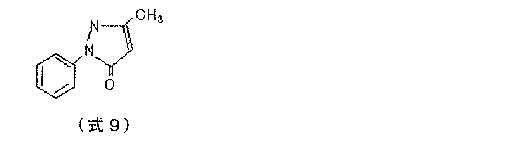
次にポリウレタンポリオールAを100質量部に対し、コロネート2521(商品名、日本ポリウレタン工業社製)33.4質量部、カーボンブラックMA−230(商品名、三菱化学製)15.0質量部、調整例1〜5で得られた表1における染料化合物1(式9)を樹脂成分100質量部に対し0.2質量部混合し、総固形分比30質量%になるようにMEKに溶解、混合の後、サンドミルにて均一に分散し、樹脂層形成用樹脂溶液1を得た。
Next, with respect to 100 parts by mass of polyurethane polyol A, 33.4 parts by mass of coronate 2521 (trade name, manufactured by Nippon Polyurethane Industry Co., Ltd.), 15.0 parts by mass of carbon black MA-230 (trade name, manufactured by Mitsubishi Chemical) were prepared. 0.2 parts by mass of the dye compound 1 (Formula 9) in Table 1 obtained in Examples 1 to 5 is mixed with 100 parts by mass of the resin component, and dissolved and mixed in MEK so that the total solid content ratio is 30% by mass. Thereafter, the mixture was uniformly dispersed in a sand mill to obtain a
得られた分散液について、前述の方法により膜厚約200μmのシートを作製した。得られたシートの体積抵抗率は2.1×10⁹Ω・cmであった。
さらにこの樹脂溶液を粘度10〜13cpsにMEKで希釈後、前記弾性層上に浸漬塗工した後乾燥させ、150℃にて2時間加熱処理することで弾性層外周に膜厚約15μmの導電性樹脂層を設け、実施例1の現像ローラを得た。前述の方法で測定した現像ローラの表面硬度は35.8であった。
About the obtained dispersion liquid, the sheet | seat with a film thickness of about 200 micrometers was produced by the above-mentioned method. The volume resistivity of the obtained sheet was 2.1 × 10 9 Ω · cm.
Furthermore, this resin solution is diluted with MEK to a viscosity of 10 to 13 cps, dip-coated on the elastic layer, dried, and heat-treated at 150 ° C. for 2 hours to have a conductivity of about 15 μm on the outer periphery of the elastic layer. A resin layer was provided to obtain the developing roller of Example 1. The surface hardness of the developing roller measured by the method described above was 35.8.
(実施例2)
実施例1の染料化合物1を染料化合物2に変更した以外は実施例1と同様にして、実施例2のシートおよび現像ローラを得た。
(Example 2)
A sheet and a developing roller of Example 2 were obtained in the same manner as in Example 1 except that the
(実施例3)
実施例1の染料化合物1を染料化合物3に変更した以外は実施例1と同様にして、実施例3のシートおよび現像ローラを得た。
(Example 3)
A sheet and a developing roller of Example 3 were obtained in the same manner as in Example 1 except that the
(実施例4)
実施例1の染料化合物1を染料化合物4に変更した以外は実施例1と同様にして、実施例4のシートおよび現像ローラを得た。
Example 4
A sheet and a developing roller of Example 4 were obtained in the same manner as in Example 1 except that the
(実施例5)
実施例1の染料化合物1を染料化合物5に変更した以外は実施例1と同様にして、実施例5のシートおよび現像ローラを得た。
(Example 5)
A sheet and a developing roller of Example 5 were obtained in the same manner as in Example 1 except that the
(実施例6)
実施例1の染料化合物1を染料化合物6に変更した以外は実施例1と同様にして、実施例6のシートおよび現像ローラを得た。
(Example 6)
A sheet and a developing roller of Example 6 were obtained in the same manner as in Example 1 except that the
(実施例7)
実施例1の染料化合物1を染料化合物7に変更した以外は実施例1と同様にして、実施例7のシートおよび現像ローラを得た。
(Example 7)
A sheet and a developing roller of Example 7 were obtained in the same manner as in Example 1 except that the
(実施例8)
実施例1の染料化合物1を染料化合物8に変更した以外は実施例1と同様にして、実施例8のシートおよび現像ローラを得た。
(Example 8)
A sheet and a developing roller of Example 8 were obtained in the same manner as in Example 1 except that the
(実施例9)
実施例1の染料化合物1を染料化合物9に変更した以外は実施例1と同様にして、実施例9のシートおよび現像ローラを得た。
Example 9
A sheet and a developing roller of Example 9 were obtained in the same manner as in Example 1 except that the
(実施例10)
実施例1の染料化合物1を染料化合物10に変更した以外は実施例1と同様にして、実施例10のシートおよび現像ローラを得た。
(Example 10)
A sheet and a developing roller of Example 10 were obtained in the same manner as in Example 1 except that the
(実施例11)
実施例1における染料化合物1の添加量を0.05質量部に変更した以外は実施例1と同様にして、実施例11のシートおよび現像ローラを得た。
(Example 11)
A sheet and a developing roller of Example 11 were obtained in the same manner as in Example 1 except that the addition amount of
(実施例12)
実施例1における染料化合物1の添加量を0.10質量部に変更した以外は実施例1と同様にして、実施例12のシートおよび現像ローラを得た。
(Example 12)
A sheet and a developing roller of Example 12 were obtained in the same manner as in Example 1 except that the amount of
(実施例13)
実施例1における染料化合物1の添加量を5.0質量部に変更した以外は実施例1と同様にして、実施例13のシートおよび現像ローラを得た。
(Example 13)
A sheet and a developing roller of Example 13 were obtained in the same manner as in Example 1 except that the addition amount of
(実施例14)
実施例1における染料化合物1の添加量を10.0質量部に変更した以外は実施例1と同様にして、実施例14のシートおよび現像ローラを得た。
(Example 14)
A sheet and a developing roller of Example 14 were obtained in the same manner as in Example 1 except that the amount of
(実施例15)
実施例1におけるカーボンブラックMA−230(商品名、三菱化学製)の添加量を15.0質量部から5.0質量部に変更した以外は実施例1と同様にして、実施例15のシートおよび現像ローラを得た。
(Example 15)
The sheet of Example 15 except that the amount of carbon black MA-230 (trade name, manufactured by Mitsubishi Chemical) in Example 1 was changed from 15.0 parts by mass to 5.0 parts by mass. And a developing roller.
(実施例16)
実施例1におけるカーボンブラックMA−230(商品名、三菱化学製)の添加量を15.0質量部から10.0質量部に変更した以外は実施例1と同様にして、実施例16のシートおよび現像ローラを得た。
(Example 16)
The sheet of Example 16 was the same as Example 1 except that the amount of carbon black MA-230 (trade name, manufactured by Mitsubishi Chemical) in Example 1 was changed from 15.0 parts by mass to 10.0 parts by mass. And a developing roller.
(実施例17)
実施例1におけるカーボンブラックMA−230(商品名、三菱化学製)の添加量を15.0質量部から25.0質量部に変更した以外は実施例1と同様にして、実施例17のシートおよび現像ローラを得た。
(Example 17)
The sheet of Example 17 was the same as Example 1 except that the amount of carbon black MA-230 (trade name, manufactured by Mitsubishi Chemical) in Example 1 was changed from 15.0 parts by mass to 25.0 parts by mass. And a developing roller.
(実施例18)
実施例1におけるカーボンブラックMA−230(商品名、三菱化学製)の添加量を15.0質量部から30.0質量部に変更した以外は実施例1と同様にして、実施例18のシートおよび現像ローラを得た。
(Example 18)
The sheet of Example 18 except that the amount of carbon black MA-230 (trade name, manufactured by Mitsubishi Chemical) in Example 1 was changed from 15.0 parts by mass to 30.0 parts by mass. And a developing roller.
(実施例19)
実施例1におけるポリウレタンポリオールAをポリエステルウレタン樹脂ニッポラン5033(商品名、日本ポリウレタン工業社製)に変更した以外は実施例1と同様にして、実施例19のシートおよび現像ローラを得た。
(Example 19)
A sheet and a developing roller of Example 19 were obtained in the same manner as in Example 1 except that the polyurethane polyol A in Example 1 was changed to polyester urethane resin NIPPOLAN 5033 (trade name, manufactured by Nippon Polyurethane Industry Co., Ltd.).
(実施例20)
実施例1におけるポリウレタンポリオールAを熱可塑性ウレタン樹脂レザミンP−1045(商品名、大日精化工業社製)に変更した以外は実施例1と同様にして、実施例20のシートおよび現像ローラを得た。
(Example 20)
A sheet and a developing roller of Example 20 are obtained in the same manner as in Example 1 except that the polyurethane polyol A in Example 1 is changed to thermoplastic urethane resin Rezamin P-1045 (trade name, manufactured by Dainichi Seika Kogyo Co., Ltd.). It was.
(実施例21)
実施例1におけるコロネート2521(商品名、日本ポリウレタン工業社製)33.4質量部をメラミン樹脂サイメル712(商品名、日本サイテック社製)25.0質量部に変更した以外は実施例1と同様にして、実施例21のシートおよび現像ローラを得た。
(Example 21)
Example 3 was the same as Example 1 except that 33.4 parts by mass of Coronate 2521 (trade name, manufactured by Nippon Polyurethane Industry Co., Ltd.) in Example 1 was changed to 25.0 parts by mass of melamine resin Cymel 712 (trade name, manufactured by Nippon Cytec Co., Ltd.). Thus, a sheet and a developing roller of Example 21 were obtained.
以下に本発明の比較例について詳細に述べる。 The comparative example of the present invention will be described in detail below.
(比較例1)
実施例1における染料化合物1を除いた以外は実施例1と同様にして、比較例1のシートおよび現像ローラを得た。
(Comparative Example 1)
A sheet and a developing roller of Comparative Example 1 were obtained in the same manner as in Example 1 except that the
(比較例2)
比較例1におけるカーボンブラックMA−230 15.0質量部をカーボンブラックMA−11(商品名、三菱化学製)40.0質量部に変更した以外は比較例1と同様にして、比較例2のシートおよび現像ローラを得た。
(Comparative Example 2)
Comparative Example 2 is the same as Comparative Example 1 except that 15.0 parts by mass of carbon black MA-230 in Comparative Example 1 is changed to 40.0 parts by mass of carbon black MA-11 (trade name, manufactured by Mitsubishi Chemical). A sheet and a developing roller were obtained.
(比較例3)
比較例1におけるカーボンブラックMA−230 15.0質量部をカーボンブラックFW−200(商品名、デグサジャパン社製)10.0質量部に変更した以外は比較例1と同様にして、比較例3のシートおよび現像ローラを得た。
(Comparative Example 3)
Comparative Example 3 is the same as Comparative Example 1 except that 15.0 parts by mass of Carbon Black MA-230 in Comparative Example 1 is changed to 10.0 parts by mass of Carbon Black FW-200 (trade name, manufactured by Degussa Japan). Sheet and a developing roller were obtained.
(比較例4)
実施例1における染料化合物1を4,5−ジフェニルイミダゾール(キシダ化学社製、式10)に変更した以外は実施例1と同様にして、比較例4のシートおよび現像ローラを得た。
(Comparative Example 4)
A sheet and a developing roller of Comparative Example 4 were obtained in the same manner as in Example 1, except that the
(比較例5)
実施例1における染料化合物1を2−(1−ナフチル)−5−フェニルオキサゾール(キシダ化学社製、式11)に変更した以外は実施例1と同様にして、比較例5のシートおよび現像ローラを得た。
(Comparative Example 5)
The sheet and developing roller of Comparative Example 5 were the same as Example 1 except that
(比較例6)
実施例1における染料化合物1をアントラキノン系染料フィラミッドブルーR(商品名、チバ・スペシャルティ・ケミカルズ社製、C.I.Solvent Blue132)に変更した以外は実施例1と同様にして、比較例6のシートおよび現像ローラを得た。
(Comparative Example 6)
Comparative Example 6 was carried out in the same manner as in Example 1 except that the
(比較例7)
実施例1における染料化合物1をピラゾロン系顔料イルガライトオレンジP(商品名、チバ・スペシャルティ・ケミカルズ社製、C.I.Pigment Orange13)に変更した以外は実施例1と同様にして、比較例7のシートおよび現像ローラを得た。
(Comparative Example 7)
Comparative Example 7 was performed in the same manner as in Example 1 except that the
以上のようにして得られた実施例1〜21及び比較例1〜6のシートについて、体積抵抗率を測定した。また得られた現像ローラの抵抗ばらつき、表面硬度を測定した。 Volume resistivity was measured about the sheet | seat of Examples 1-21 and Comparative Examples 1-6 obtained as mentioned above. Further, resistance variation and surface hardness of the obtained developing roller were measured.
ローラの軸方向抵抗ばらつき(Δ)は、軸芯体の両端に500gの荷重をかけて、ローラを60rpmの速度で回転させながら、金属製のドラムに押し当て、ローラと金属製ドラムの間に50Vの電圧を印加し、ローラ両端部から3cmの部位及び中心部の3点における抵抗値の最大値と最小値を計測し、1−(抵抗値の最大値/抵抗値の最小値)の値を軸方向の抵抗ばらつきとした。 The axial resistance variation (Δ) of the roller is determined by applying a load of 500 g on both ends of the shaft core and pressing the roller against the metal drum while rotating the roller at a speed of 60 rpm. Apply a voltage of 50V, measure the maximum and minimum values of resistance at 3 points from the roller ends and 3 points at the center, 1- (maximum resistance value / minimum resistance value) Is the resistance variation in the axial direction.
ローラの周方向抵抗バラツキ(Δ)は、軸芯体の両端に500gの荷重をかけて、ローラを60rpmの速度で回転させながら、金属製のドラムに押し当て、ローラと金属製ドラムの間に50Vの電圧を印加し、1周中での抵抗値の最大値と最小値を計測し、1−(抵抗値の最大値/抵抗値の最小値)の値を周方向の抵抗ばらつきとした。 The circumferential resistance variation (Δ) of the roller is determined by applying a load of 500 g on both ends of the shaft core and pressing the roller against the metal drum while rotating the roller at a speed of 60 rpm. A voltage of 50 V was applied, the maximum value and the minimum value of the resistance value in one circuit were measured, and the value of 1- (maximum value of resistance value / minimum value of resistance value) was regarded as resistance variation in the circumferential direction.
ローラサンプル間の抵抗ばらつきは、軸芯体の両端に500gの荷重をかけて、ローラを60rpmの速度で回転させながら、金属製のドラムに押し当て、ローラと金属製ドラムの間に50Vの電圧を印加し、ローラ全体の抵抗値の最大値と最小値を計測し、1−(抵抗値の最大値/抵抗値の最小値)の値をローラサンプル間の抵抗ばらつきとした。 The resistance variation between roller samples was applied to a metal drum while applying a load of 500 g on both ends of the shaft core and rotating the roller at a speed of 60 rpm, and a voltage of 50 V between the roller and the metal drum. Was applied, and the maximum and minimum resistance values of the entire roller were measured. A value of 1- (maximum resistance value / minimum resistance value) was defined as resistance variation between roller samples.
以上の測定結果を以下の基準で評価した。
◎:抵抗ばらつきが0以上0.5未満
○:抵抗ばらつきが0.6以上1.0未満
△:抵抗ばらつきが1.0以上
以上の結果を表2〜5に示す。
The above measurement results were evaluated according to the following criteria.
A: Resistance variation of 0 or more and less than 0.5 ○: Resistance variation of 0.6 or more and less than 1.0 Δ: Results of resistance variation of 1.0 or more are shown in Tables 2 to 5.
次に得られた現像ローラについて、前述の方法で画像耐久性の評価を行った。カブリ、ゴースト及び画像濃度を以下の基準で評価した。
カブリ
◎:3%未満
○:3%以上5%未満
△:5%以上
ゴースト
◎:ゴーストが全く認められない
○:極軽微なゴーストが認められる
△:顕著なゴーストが認められる
画像濃度(ベタ画像)
◎:濃度が1.3以上
○:濃度が1.1以上1.3未満
△:濃度が1.1未満
以上の結果を表6〜8に示す。
Next, the obtained developing roller was evaluated for image durability by the method described above. The fog, ghost and image density were evaluated according to the following criteria.
Fog ◎: Less than 3% ○: 3% or more and less than 5% △: 5% or more ghost ◎: No ghost observed ○: Very slight ghost recognized △: Remarkable ghost recognized
Image density (solid image)
◎: Concentration is 1.3 or more ○: Concentration is 1.1 or more and less than 1.3 Δ: Concentration is less than 1.1
The above results are shown in Tables 6-8.
実施例1〜21は、染料化合物による導電性向上のため導電性フィラーの含有量を著しく増やすことなく高い導電性を示す。そのためローラの抵抗ばらつきが小さく、かつ柔軟なローラとなり、高い画像品質を示している。特に染料化合物の分子量が350〜430である実施例4、5、6のローラは、抵抗ばらつき抑制と導電性、柔軟性を高い次元で両立し、高品位の画像が得られている。 Examples 1-21 show high electroconductivity, without increasing the content of an electroconductive filler remarkably for the electroconductive improvement by a dye compound. Therefore, the resistance variation of the roller is small and the roller is flexible and shows high image quality. In particular, the rollers of Examples 4, 5, and 6 in which the molecular weight of the dye compound is 350 to 430 satisfy both resistance resistance suppression, conductivity, and flexibility at a high level, and high-quality images are obtained.
それに対し低導電性のカーボンブラックで導電性を発現するためにカーボンブラックを高い比率で含有する比較例2は著しい硬度の上昇が見られ、画像弊害を引き起こしている。また高導電性のカーボンブラックを用いて導電性を付与した比較例3は顕著な抵抗ばらつきの増大やリークによる画像弊害が認められる。また本発明の染料化合物を含有しない比較例1やイミダゾール系、オキサゾール系、アントラキノン系の染料化合物や、溶解性の著しく低い顔料形態のピラゾロン化合物は現像ローラとして好適な導電性が得られず、画像品質の低下が認められた。 On the other hand, Comparative Example 2 containing carbon black at a high ratio in order to develop conductivity with low-conductivity carbon black shows a significant increase in hardness, causing image defects. Further, in Comparative Example 3 in which conductivity is imparted using highly conductive carbon black, there is a marked increase in resistance variation and image defects due to leakage. Further, Comparative Example 1 that does not contain the dye compound of the present invention, imidazole-based, oxazole-based, anthraquinone-based dye compounds, and pyrazolone compounds in the form of pigments with extremely low solubility do not provide a suitable conductivity as a developing roller, and image A decrease in quality was observed.
1:現像ローラ
2:軸芯体
3:弾性層
4:導電性樹脂層
5:感光体
6:現像ローラ
7:トナー供給ローラ
8:トナー
9:規制ブレード
10:現像装置
11:レーザー光
12:帯電装置
13:クリーニング装置
14:クリーニング用帯電装
置
15:定着装置
16:駆動ローラ
17:転写ローラ
18:バイアス電源
19:テンションローラー
20:転写搬送ベルト
21:従動ローラ
22:紙
23:給紙ローラ
24:吸着ローラ
25:浸漬槽
26:液送ポンプ
27:撹拌タンク
28:昇降装置
29:内部抵抗
30:金属電極ローラ
1: Developing roller 2: Shaft core 3: Elastic layer 4: Conductive resin layer 5: Photoreceptor 6: Developing roller 7: Toner supply roller 8: Toner 9: Regulator blade 10: Developing device 11: Laser beam 12: Charging Device 13: Cleaning device 14: Cleaning charging device 15: Fixing device 16: Driving roller 17: Transfer roller 18: Bias power source 19: Tension roller 20: Transfer conveyance belt 21: Driven roller 22: Paper 23: Paper feed roller 24: Adsorption roller 25: immersion tank 26: liquid feed pump 27: stirring tank 28: lifting device 29: internal resistance 30: metal electrode roller
Claims (9)
該樹脂層が樹脂成分、ピラゾロン骨格を有する染料化合物および導電性微粒子を含有することを特徴とする現像ローラ。 A mandrel, in the developing roller having a resin layer which is the outermost layer,
Developing row La, characterized in that the resin layer is a resin component, containing a dye compound and conductive fine particles having a pyrazolone skeleton.
Priority Applications (1)
| Application Number | Priority Date | Filing Date | Title |
|---|---|---|---|
| JP2006294231A JP5049552B2 (en) | 2006-10-30 | 2006-10-30 | Developing roller, process cartridge, and image forming apparatus |
Applications Claiming Priority (1)
| Application Number | Priority Date | Filing Date | Title |
|---|---|---|---|
| JP2006294231A JP5049552B2 (en) | 2006-10-30 | 2006-10-30 | Developing roller, process cartridge, and image forming apparatus |
Publications (3)
| Publication Number | Publication Date |
|---|---|
| JP2008111951A JP2008111951A (en) | 2008-05-15 |
| JP2008111951A5 JP2008111951A5 (en) | 2009-12-17 |
| JP5049552B2 true JP5049552B2 (en) | 2012-10-17 |
Family
ID=39444495
Family Applications (1)
| Application Number | Title | Priority Date | Filing Date |
|---|---|---|---|
| JP2006294231A Expired - Fee Related JP5049552B2 (en) | 2006-10-30 | 2006-10-30 | Developing roller, process cartridge, and image forming apparatus |
Country Status (1)
| Country | Link |
|---|---|
| JP (1) | JP5049552B2 (en) |
Families Citing this family (2)
| Publication number | Priority date | Publication date | Assignee | Title |
|---|---|---|---|---|
| CA3121202A1 (en) | 2018-11-30 | 2020-06-04 | Nuvation Bio Inc. | Pyrrole and pyrazole compounds and methods of use thereof |
| CN118772059B (en) * | 2023-04-06 | 2026-01-30 | 天津农学院 | Preparation methods and applications of bis(4-pyrazolone)methane compounds |
Family Cites Families (5)
| Publication number | Priority date | Publication date | Assignee | Title |
|---|---|---|---|---|
| JP2001117348A (en) * | 1999-10-15 | 2001-04-27 | Canon Inc | Developing roller, developing device and developing method |
| JP4532700B2 (en) * | 2000-08-24 | 2010-08-25 | キヤノン株式会社 | Developer carrying member and image forming method |
| JP4262044B2 (en) * | 2003-10-10 | 2009-05-13 | キヤノン株式会社 | Developing roller, electrophotographic process cartridge, and electrophotographic image forming apparatus |
| JP4663360B2 (en) * | 2004-03-19 | 2011-04-06 | キヤノン株式会社 | Developing roller |
| JP4939078B2 (en) * | 2006-02-24 | 2012-05-23 | キヤノン株式会社 | Developing roller, process cartridge, electrophotographic device |
-
2006
- 2006-10-30 JP JP2006294231A patent/JP5049552B2/en not_active Expired - Fee Related
Also Published As
| Publication number | Publication date |
|---|---|
| JP2008111951A (en) | 2008-05-15 |
Similar Documents
| Publication | Publication Date | Title |
|---|---|---|
| US8182405B2 (en) | Developing roller, developing roller production method, process cartridge, and electrophotographic apparatus | |
| US10642186B2 (en) | Developing member having outer surface with independent electrically insulating domains, electrophotographic process cartridge, and electrophotographic image forming apparatus | |
| JP4360447B1 (en) | Developing roller and manufacturing method thereof, process cartridge, and electrophotographic image forming apparatus | |
| WO2014002152A1 (en) | Development member, process cartridge, and electrophotography device | |
| JP2018022074A (en) | Electrophotographic member, process cartridge and electrophotographic device | |
| US6393243B1 (en) | Developing roller and developing device using the same | |
| JP5196956B2 (en) | Developing roller, developing roller manufacturing method, process cartridge, and electrophotographic apparatus | |
| JP6669394B2 (en) | Developer carrier, process cartridge, and electrophotographic image forming apparatus | |
| JP4745793B2 (en) | Elastic roller, developing device and image forming apparatus | |
| JP5049552B2 (en) | Developing roller, process cartridge, and image forming apparatus | |
| JP4939078B2 (en) | Developing roller, process cartridge, electrophotographic device | |
| JP3907632B2 (en) | Developing roller, process cartridge, and electrophotographic apparatus | |
| JP5700972B2 (en) | Developing roller, developing device, and electrophotographic apparatus | |
| JP5361342B2 (en) | Developing roller, developing roller manufacturing method, process cartridge, and electrophotographic image forming apparatus | |
| JP5022686B2 (en) | Developing roller manufacturing method | |
| JP5717512B2 (en) | Developing roller, developing roller manufacturing method, process cartridge, and electrophotographic apparatus | |
| JP4194512B2 (en) | Developing roller, electrophotographic process cartridge, and electrophotographic image forming apparatus | |
| JP4865318B2 (en) | Developing roller, manufacturing method thereof, process cartridge, and image forming apparatus | |
| JP5049548B2 (en) | Developing roller, developing device, and image forming apparatus | |
| JP4612830B2 (en) | Developing roller and developing device for electrophotographic apparatus using the same | |
| JP4651083B2 (en) | Developing roller, electrophotographic process cartridge, and image forming apparatus | |
| US20250244694A1 (en) | Developing roller, developing cartridge, process cartridge, and electrophotographic image forming apparatus | |
| JP4912383B2 (en) | Developing roller, electrophotographic process cartridge, electrophotographic image forming apparatus | |
| JPH11352770A (en) | Toner carrying body and image forming device | |
| JP2010156758A (en) | Developing roller, developing device using the same, process cartridge, image forming apparatus, and method for manufacturing the developing roller |
Legal Events
| Date | Code | Title | Description |
|---|---|---|---|
| A521 | Request for written amendment filed |
Free format text: JAPANESE INTERMEDIATE CODE: A523 Effective date: 20091030 |
|
| A621 | Written request for application examination |
Free format text: JAPANESE INTERMEDIATE CODE: A621 Effective date: 20091030 |
|
| A977 | Report on retrieval |
Free format text: JAPANESE INTERMEDIATE CODE: A971007 Effective date: 20120712 |
|
| TRDD | Decision of grant or rejection written | ||
| A01 | Written decision to grant a patent or to grant a registration (utility model) |
Free format text: JAPANESE INTERMEDIATE CODE: A01 Effective date: 20120717 |
|
| A01 | Written decision to grant a patent or to grant a registration (utility model) |
Free format text: JAPANESE INTERMEDIATE CODE: A01 |
|
| A61 | First payment of annual fees (during grant procedure) |
Free format text: JAPANESE INTERMEDIATE CODE: A61 Effective date: 20120723 |
|
| FPAY | Renewal fee payment (event date is renewal date of database) |
Free format text: PAYMENT UNTIL: 20150727 Year of fee payment: 3 |
|
| R151 | Written notification of patent or utility model registration |
Ref document number: 5049552 Country of ref document: JP Free format text: JAPANESE INTERMEDIATE CODE: R151 |
|
| LAPS | Cancellation because of no payment of annual fees |