JP5048849B2 - Medical electrical lead with proximal protection - Google Patents
Medical electrical lead with proximal protection Download PDFInfo
- Publication number
- JP5048849B2 JP5048849B2 JP2010546925A JP2010546925A JP5048849B2 JP 5048849 B2 JP5048849 B2 JP 5048849B2 JP 2010546925 A JP2010546925 A JP 2010546925A JP 2010546925 A JP2010546925 A JP 2010546925A JP 5048849 B2 JP5048849 B2 JP 5048849B2
- Authority
- JP
- Japan
- Prior art keywords
- lead
- region
- lead body
- protective layer
- proximal
- Prior art date
- Legal status (The legal status is an assumption and is not a legal conclusion. Google has not performed a legal analysis and makes no representation as to the accuracy of the status listed.)
- Expired - Fee Related
Links
- 239000011241 protective layer Substances 0.000 claims description 61
- 239000010410 layer Substances 0.000 claims description 27
- 229920000295 expanded polytetrafluoroethylene Polymers 0.000 claims description 18
- 239000004020 conductor Substances 0.000 claims description 15
- 239000002861 polymer material Substances 0.000 claims description 15
- 238000003780 insertion Methods 0.000 claims description 11
- 230000037431 insertion Effects 0.000 claims description 11
- 238000002513 implantation Methods 0.000 claims description 10
- 210000002620 vena cava superior Anatomy 0.000 claims description 9
- 239000000463 material Substances 0.000 claims description 8
- 239000012779 reinforcing material Substances 0.000 claims description 8
- 229920001343 polytetrafluoroethylene Polymers 0.000 claims description 7
- 239000004810 polytetrafluoroethylene Substances 0.000 claims description 7
- 230000000541 pulsatile effect Effects 0.000 claims description 7
- 210000001519 tissue Anatomy 0.000 claims description 7
- 210000000748 cardiovascular system Anatomy 0.000 claims description 4
- 210000005003 heart tissue Anatomy 0.000 claims description 3
- 230000002787 reinforcement Effects 0.000 claims description 3
- 238000007920 subcutaneous administration Methods 0.000 claims description 2
- 230000000149 penetrating effect Effects 0.000 claims 1
- 229920000642 polymer Polymers 0.000 description 28
- 210000003462 vein Anatomy 0.000 description 12
- 210000004204 blood vessel Anatomy 0.000 description 11
- 210000001321 subclavian vein Anatomy 0.000 description 11
- 230000006870 function Effects 0.000 description 10
- 238000007726 management method Methods 0.000 description 9
- 210000005245 right atrium Anatomy 0.000 description 9
- 210000003129 brachiocephalic vein Anatomy 0.000 description 7
- 238000000576 coating method Methods 0.000 description 7
- 239000011248 coating agent Substances 0.000 description 6
- 210000005241 right ventricle Anatomy 0.000 description 6
- 239000008280 blood Substances 0.000 description 5
- 210000004369 blood Anatomy 0.000 description 5
- 239000000835 fiber Substances 0.000 description 5
- 238000000034 method Methods 0.000 description 5
- 229920002635 polyurethane Polymers 0.000 description 5
- 239000004814 polyurethane Substances 0.000 description 5
- 230000001681 protective effect Effects 0.000 description 5
- 210000005166 vasculature Anatomy 0.000 description 5
- 210000002048 axillary vein Anatomy 0.000 description 3
- 238000001125 extrusion Methods 0.000 description 3
- WABPQHHGFIMREM-RKEGKUSMSA-N lead-214 Chemical compound [214Pb] WABPQHHGFIMREM-RKEGKUSMSA-N 0.000 description 3
- 210000005240 left ventricle Anatomy 0.000 description 3
- 239000002184 metal Substances 0.000 description 3
- 229910052751 metal Inorganic materials 0.000 description 3
- -1 polytetrafluoroethylene Polymers 0.000 description 3
- 230000008569 process Effects 0.000 description 3
- 230000010349 pulsation Effects 0.000 description 3
- 229920002379 silicone rubber Polymers 0.000 description 3
- 239000004945 silicone rubber Substances 0.000 description 3
- 230000001225 therapeutic effect Effects 0.000 description 3
- 230000015572 biosynthetic process Effects 0.000 description 2
- 230000000747 cardiac effect Effects 0.000 description 2
- 238000009125 cardiac resynchronization therapy Methods 0.000 description 2
- 230000006835 compression Effects 0.000 description 2
- 238000007906 compression Methods 0.000 description 2
- 210000003748 coronary sinus Anatomy 0.000 description 2
- 238000010586 diagram Methods 0.000 description 2
- 230000000694 effects Effects 0.000 description 2
- 230000002708 enhancing effect Effects 0.000 description 2
- 239000004744 fabric Substances 0.000 description 2
- 238000012986 modification Methods 0.000 description 2
- 230000004048 modification Effects 0.000 description 2
- 229910001000 nickel titanium Inorganic materials 0.000 description 2
- 230000003014 reinforcing effect Effects 0.000 description 2
- 210000000591 tricuspid valve Anatomy 0.000 description 2
- 230000002792 vascular Effects 0.000 description 2
- 230000002861 ventricular Effects 0.000 description 2
- VGGSQFUCUMXWEO-UHFFFAOYSA-N Ethene Chemical compound C=C VGGSQFUCUMXWEO-UHFFFAOYSA-N 0.000 description 1
- 239000005977 Ethylene Substances 0.000 description 1
- 229920000271 Kevlar® Polymers 0.000 description 1
- 235000014676 Phragmites communis Nutrition 0.000 description 1
- 239000004698 Polyethylene Substances 0.000 description 1
- HZEWFHLRYVTOIW-UHFFFAOYSA-N [Ti].[Ni] Chemical compound [Ti].[Ni] HZEWFHLRYVTOIW-UHFFFAOYSA-N 0.000 description 1
- 230000003187 abdominal effect Effects 0.000 description 1
- 238000007792 addition Methods 0.000 description 1
- 239000000853 adhesive Substances 0.000 description 1
- 230000001070 adhesive effect Effects 0.000 description 1
- 229910045601 alloy Inorganic materials 0.000 description 1
- 239000000956 alloy Substances 0.000 description 1
- 230000004075 alteration Effects 0.000 description 1
- 238000004873 anchoring Methods 0.000 description 1
- 230000008901 benefit Effects 0.000 description 1
- 230000005540 biological transmission Effects 0.000 description 1
- 210000000988 bone and bone Anatomy 0.000 description 1
- 238000007598 dipping method Methods 0.000 description 1
- 239000012777 electrically insulating material Substances 0.000 description 1
- 239000012530 fluid Substances 0.000 description 1
- 230000006872 improvement Effects 0.000 description 1
- 239000007769 metal material Substances 0.000 description 1
- 210000003205 muscle Anatomy 0.000 description 1
- HLXZNVUGXRDIFK-UHFFFAOYSA-N nickel titanium Chemical compound [Ti].[Ti].[Ti].[Ti].[Ti].[Ti].[Ti].[Ti].[Ti].[Ti].[Ti].[Ni].[Ni].[Ni].[Ni].[Ni].[Ni].[Ni].[Ni].[Ni].[Ni].[Ni].[Ni].[Ni].[Ni] HLXZNVUGXRDIFK-UHFFFAOYSA-N 0.000 description 1
- 230000002093 peripheral effect Effects 0.000 description 1
- 229920000573 polyethylene Polymers 0.000 description 1
- 229920001296 polysiloxane Polymers 0.000 description 1
- 230000001737 promoting effect Effects 0.000 description 1
- 230000009993 protective function Effects 0.000 description 1
- 230000001105 regulatory effect Effects 0.000 description 1
- 239000012783 reinforcing fiber Substances 0.000 description 1
- 230000008439 repair process Effects 0.000 description 1
- 238000005507 spraying Methods 0.000 description 1
- 239000010935 stainless steel Substances 0.000 description 1
- 229910001220 stainless steel Inorganic materials 0.000 description 1
- 230000000638 stimulation Effects 0.000 description 1
- 238000001356 surgical procedure Methods 0.000 description 1
- 229920002994 synthetic fiber Polymers 0.000 description 1
- 239000012209 synthetic fiber Substances 0.000 description 1
- 238000007740 vapor deposition Methods 0.000 description 1
- 210000001631 vena cava inferior Anatomy 0.000 description 1
Images


Classifications
-
- A—HUMAN NECESSITIES
- A61—MEDICAL OR VETERINARY SCIENCE; HYGIENE
- A61N—ELECTROTHERAPY; MAGNETOTHERAPY; RADIATION THERAPY; ULTRASOUND THERAPY
- A61N1/00—Electrotherapy; Circuits therefor
- A61N1/02—Details
- A61N1/04—Electrodes
- A61N1/05—Electrodes for implantation or insertion into the body, e.g. heart electrode
- A61N1/056—Transvascular endocardial electrode systems
Landscapes
- Health & Medical Sciences (AREA)
- Heart & Thoracic Surgery (AREA)
- Vascular Medicine (AREA)
- Cardiology (AREA)
- Engineering & Computer Science (AREA)
- Biomedical Technology (AREA)
- Nuclear Medicine, Radiotherapy & Molecular Imaging (AREA)
- Radiology & Medical Imaging (AREA)
- Life Sciences & Earth Sciences (AREA)
- Animal Behavior & Ethology (AREA)
- General Health & Medical Sciences (AREA)
- Public Health (AREA)
- Veterinary Medicine (AREA)
- Electrotherapy Devices (AREA)
Description
本発明は、拍動管理システムで使用される医療用電気リードに関する。より詳細には、患者の心臓に対して部分的に植え込まれる医療用電気リードに関する。 The present invention relates to a medical electrical lead used in a pulsation management system. More particularly, it relates to a medical electrical lead that is partially implanted into a patient's heart.
拍動管理システムで使用される医療用電気リードとしては、様々なリードが公知である。通常、それらのリードは血管内を介して患者の心臓の内部又は表面の植え込み位置まで延び、心臓の電気的活動の感知、治療的刺激の送達等を行うパルス発生器又はその他の埋め込み型装置に接続される。リードは、患者の自然な動きに対応できるように高い可撓性を有していることが望ましく、またできるだけ小型であることが好ましい。加えて、リードには、患者の筋肉組織や骨組織、パルス発生器、他のリード、植え込み手術や除去手術に用いる手術器具等からの外力が加えられる。したがって、リードの設計は常に改良を必要としている。 Various medical electrical leads used in the pulsation management system are known. Typically, these leads extend through the blood vessels to the implantation location in or on the patient's heart, to pulse generators or other implantable devices that sense cardiac electrical activity, deliver therapeutic stimuli, etc. Connected. The lead is preferably highly flexible to accommodate the natural movement of the patient and is preferably as small as possible. In addition, external force is applied to the lead from a patient's muscle tissue and bone tissue, a pulse generator, another lead, a surgical instrument used for implantation or removal surgery, and the like. Therefore, the lead design always needs improvement.
本発明の目的は、基端側に保護を有する医療用電気リードを提供することにある。 It is an object of the present invention to provide a medical electrical lead having protection on the proximal side.
本発明の一実施形態は、拍動管理システムにおいてパルス発生器に接続される医療用電気リードに関する。このリードは、基端コネクタ、可撓性を有するリード本体、保護層、少なくとも1つの電極、及び少なくとも1つの導電体を備える。基端コネクタは、リードをパルス発生器に対して機械的及び電気的に接続する。可撓性を有するリード本体は、コネクタから先端方向に延び、基端領域と、中間領域と、先端チップで終結する先端領域とを形成する。保護層は、リード本体の基端領域上に配置され、リード本体の先端領域上には配置されない。また保護層は、耐摩耗性を有する滑らかな外面を有するポリマー材と、保護層内に配置された補強材とを有する。電極は、リード本体の先端領域に接続される。導電体は電極からコネクタまで延び、少なくとも1つの電極をコネクタに対して電気的に接続する。 One embodiment of the present invention relates to a medical electrical lead connected to a pulse generator in a pulsatile management system. The lead includes a proximal connector, a flexible lead body, a protective layer, at least one electrode, and at least one electrical conductor. The proximal connector mechanically and electrically connects the lead to the pulse generator. The lead body having flexibility extends from the connector in the distal direction, and forms a proximal end region, an intermediate region, and a distal end region that terminates at the distal tip. The protective layer is disposed on the proximal end region of the lead body and is not disposed on the distal end region of the lead body. The protective layer also includes a polymer material having a smooth outer surface having wear resistance and a reinforcing material disposed in the protective layer. The electrode is connected to the tip region of the lead body. A conductor extends from the electrode to the connector and electrically connects at least one electrode to the connector.
本発明の別の実施形態は、拍動管理システムにおいてパルス発生器に接続される医療用電気リードに関する。このリードは、同リードを機械的及び電気的にパルス発生器に接続する基端コネクタ、可撓性を有し、コネクタから先端方向に延びるリード本体、少なくとも1つの電極、及び少なくとも1つの導電体を備える。リード本体は、基端領域と、中間領域と、先端チップで終結する先端領域とを形成する。電極は、リード本体の先端領域に接続される。導電体は電極からコネクタまで延びて、少なくとも1つの電極をコネクタに対して電気的に接続する。リードは、少なくとも基端領域の耐摩耗性を強化及び向上させるための保護手段を備える。保護手段は、リード本体の基端領域上には配置されるが、リード本体の先端領域上には配置されない。 Another embodiment of the invention relates to a medical electrical lead connected to a pulse generator in a pulsatile management system. The lead includes a proximal connector for mechanically and electrically connecting the lead to the pulse generator, a flexible lead body extending in a distal direction from the connector, at least one electrode, and at least one conductor. Is provided. The lead body forms a proximal region, an intermediate region, and a distal region that terminates at the distal tip. The electrode is connected to the tip region of the lead body. An electrical conductor extends from the electrode to the connector and electrically connects at least one electrode to the connector. The lead includes protective means for enhancing and improving wear resistance at least in the proximal region. The protection means is disposed on the proximal end region of the lead body, but is not disposed on the distal end region of the lead body.
本発明のさらなる別の実施形態は、拍動管理システムにおいてパルス発生器に接続される医療用電気リードに関する。このリードは、基端コネクタ、可撓性を有するリード本体、保護層、少なくとも1つの電極、及び少なくとも1つの導電体を備える。基端コネクタは、リードを機械的及び電気的にパルス発生器に接続する。リード本体は、コネクタから先端方向に延び、基端領域と、中間領域と、先端領域とを形成する。基端領域は、皮下に植え込まれ、かつパルス発生器の植え込み位置から、心臓血管系への挿入部位より先端側の位置まで延びる長さを有する。中間領域は、基端領域から、患者の心臓の上大静脈より先端側の位置まで先端方向に延びる。先端領域は、先端チップにおいて終結し、かつ患者の心臓内において前記中間領域から先端方向に延びる。保護層は、リード本体の基端領域上及び中間領域上のみに配置される。また保護層は、滑らかなポリマー材を有し、コネクタから先端方向に延び、かつリード本体の中間領域より基端側で終結する。電極は、リード本体の先端領域に接続される。導電体は電極からコネクタまで延びて、少なくとも1つの電極をコネクタに対して電気的に接続する。 Yet another embodiment of the present invention relates to a medical electrical lead connected to a pulse generator in a pulsatile management system. The lead includes a proximal connector, a flexible lead body, a protective layer, at least one electrode, and at least one electrical conductor. The proximal connector mechanically and electrically connects the lead to the pulse generator. The lead body extends from the connector in the distal direction, and forms a proximal end region, an intermediate region, and a distal end region. The proximal region is implanted subcutaneously and has a length that extends from the implantation location of the pulse generator to a location distal to the insertion site into the cardiovascular system. The middle region extends distally from the proximal region to a position distal to the superior vena cava of the patient's heart. The distal region terminates at the distal tip and extends distally from the intermediate region within the patient's heart. The protective layer is disposed only on the proximal end region and the intermediate region of the lead body. The protective layer has a smooth polymer material, extends from the connector in the distal direction, and terminates on the proximal side from the intermediate region of the lead body. The electrode is connected to the tip region of the lead body. An electrical conductor extends from the electrode to the connector and electrically connects at least one electrode to the connector.
複数の実施形態が開示されているが、当業者であれば、本発明の例示となる実施形態を示し説明する以下の詳細な説明から、本発明のさらに他の実施形態が明白になるであろう。従って、図面および詳細な説明は、例示的なものであり、本発明を限定するものではない。 While multiple embodiments are disclosed, further embodiments of the present invention will become apparent to those skilled in the art from the following detailed description, which illustrates and describes illustrative embodiments of the invention. Let's go. Accordingly, the drawings and detailed description are illustrative and are not restrictive of the invention.
本発明は種々の別例で実施可能であるが、特定の実施形態を例として図面に示し、以下で詳細に説明する。ただし、本発明を特定の実施形態に限定することを意図するものではなく、むしろ、添付の特許請求の範囲によって定義される本発明の範囲に含まれるすべての変更例を包含するものである。 While the invention is amenable to various alternative embodiments, specific embodiments have been shown by way of example in the drawings and are described in detail below. However, it is not intended to limit the invention to the specific embodiments, but rather encompasses all modifications that fall within the scope of the invention as defined by the appended claims.
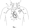
図1は、本発明の一実施形態による拍動管理(CRM)システム10の概略図である。図1に示されるように、CRMシステム10は、患者の心臓18に配置された複数のリード14、16に接続されたパルス発生器12を備えている。さらに図1に示されるように、心臓18は、三尖弁28で隔離された右心房24及び右心室26を有する。心臓18が正常に機能している場合、非酸素化血液が上大静脈30及び下大静脈32を介して右心房24に供給される。上大静脈30に血液を供給している主要な静脈には、右鎖骨下静脈38及び左鎖骨下静脈40に血液を送る右腋窩静脈34及び左腋窩静脈36が含まれる。右外顎静脈42及び左外顎静脈44が、右内顎静脈46及び左内顎静脈48と共に右鎖骨下静脈38と左鎖骨下静脈40とを連結し、右腕頭静脈50及び左腕頭静脈52を形成している。そして、これらの右腕頭静脈50及び左腕頭静脈52が連結して上大静脈30に血液を送っている。
FIG. 1 is a schematic diagram of a pulsation management (CRM)
リード14及び16は、心臓18とパルス発生器12の間で電気信号及び刺激を伝達する。図1の実施形態では、リード14が右心室26に植え込まれ、リード16が右心房24に植え込まれる。他の実施形態では、CRMシステム10は、他のリード、例えば、両心室ペーシングや心臓再同期療法において左心室を刺激するために冠状静脈まで延びるリード等を含んでいてもよい。図に示されるように、リード14及び16は、左鎖骨下静脈40の血管壁に形成された血管への挿入部位54を介して血管系に挿入され、左腕頭静脈52及び上大静脈30内を延び、リード14は右心室26に、リード16は右心房24にそれぞれ植え込まれる。他の実施形態では、リード14及び16は、右鎖骨下静脈38、左腋窩静脈36、左外顎静脈44、左内顎静脈48又は左腕頭静脈52を介して血管系に挿入される。
通常、パルス発生器12は植え込み位置内、若しくは患者の胸部又は腹部の嚢内に、皮下に植え込まれる。パルス発生器12は、当業者に周知の植え込み型医療器具を用いてもよいし、患者への治療的刺激の送達を目的として新たに開発されたものを用いてもよい。いくつかの実施形態では、パルス発生器12は、ペースメーカや植え込み型除細動器であってもよいし、ペーシング機能及び除細動機能を備えたものであってもよい。リード14及び16において、パルス発生器12と血管への挿入部位54との間の部分は、皮下又は筋肉下のいずれに位置していてもよい。リードの余剰長さ分、すなわち、パルス発生器12から心臓内の所望の植え込み部位への到達に必要な長さ以上の部分は、通常の場合、巻回された状態でパルス発生器12の近くの皮下嚢に収められる。
Typically, the
図2は、リード14の斜視図である。この図に示されるように、一実施形態では、リード14は長尺状リード本体70及びリード本体70に接続された基端コネクタ72を備える。さらに図示されるとおり、リード本体70は、基端領域76、中間領域84、先端領域88を形成している。また、リード14は、リード本体70の基端領域76に保護層90を有する。基端領域76は、植え込まれたパルス発生器12から延び、血管系、例えば、血管への挿入部位54の先端側すぐに位置する左鎖骨下静脈40(図1参照)に挿入され得る長さを有している。したがって、基端領域76は、リード14が植え込まれた状態においてはその大部分が皮下に位置し、端の部分が血管内に延びる。
FIG. 2 is a perspective view of the
中間領域84は、基端領域76、すなわち、血管への挿入部位54より先端側すぐから延び、左鎖骨下静脈40及び左腕頭静脈52を介して上大静脈30に挿入され得る長さを有する。先端領域88は心臓内領域として構成されるため、右心房24に挿入され、三尖弁28を介して右心室26に挿入される。先端チップ100は、右心室26内に植え込まれる。図2の実施形態では、中間領域84及び先端領域88は略等径を有し、心臓12の自然な動きに対応できる可撓性を有するように構成される。また、いくつかの実施形態では、これらの領域は組織内殖を抑制又は防止するよう構成される。
The intermediate region 84 extends from the
基端領域76は、コネクタ72に接続された基端部94を有し、先端領域88は、先端チップ100において終結する。コネクタ72は、リード14をパルス発生器12のヘッド部に機械的又は電気的に接続する。リード14は、固定用らせん体106及び一対のコイル電極112、118をさらに備える。図示する実施形態では、電極112、118は、心臓18に除細動を施すために衝撃を与える電極であり、組織内殖の調節(促進又は抑制)を目的としたコーティングを各々有する。一実施形態では、電極112、118と心臓組織の間の流動的接触を密にし、かつ組織内殖及び繊維形成を実質的に防いで電極表面への固着を防止するために、延伸ポリテトラフルオロエチレン(ePTFE)コーティングが電極に施されている。さらに、固定用らせん体106は、ペーシング/感知電極として構成してもよい。他の実施形態では、患者それぞれの治療目的に応じて他の電極構成を用いてよい。
The
図2にさらに示されるように、リード14はリード本体70の基端領域76の周囲に縫合スリーブ124を有する。縫合スリーブ124は、複数の周囲溝126を有し、基端領域76を所望の植え込み状態に固定し易くしている。例えば、リード14が長手方向に自然発生的に動いてしまうのを抑制又は防止するために、縫合糸をこの溝126の中に部分的に位置させ、周囲又は近傍の筋膜繊維内に通して、固く引いて固定してもよい。縫合糸を固く引っ張ることにより、リード14が各縫合糸から圧縮力を受けるが、縫合スリーブ124がこの圧縮力をリード本体70に対して分散させることにより、リード本体70が損傷しないようにしている。
As further shown in FIG. 2, the
リード本体70は、可撓性及び生体適合性を有し、かつリードの形成に適したあらゆる材料を用いて形成可能である。いくつかの実施形態では、リード本体70は、可撓性を有する電気絶縁材料により形成される。一実施形態では、リード本体70は、シリコーンゴムから形成される。別の実施形態では、リード本体70は、ポリウレタンから形成される。いくつかの実施形態では、基端領域76、中間領域84、及び先端領域88が、所望する機能に応じて互いに異なる材料で形成される。
The
保護層90は、基端領域76の周囲において、コネクタ72から中間領域84までの部分に施される。保護層90は、基端領域76の全体的な強度や耐久性を向上させる機能を有する。例えば、一実施形態においては、保護層90は基端領域76の耐摩耗性を向上させるよう構成される。基端領域76は、リード14が図1のリード16やパルス発生器12等の他の構造及び/又はデバイスと接触することにより磨耗する虞がある。
The
一実施形態では、保護層90は、高温による損傷への耐性を向上させるよう構成される。例えば、他のリードやパルス発生器12を交換及び/又は修理するために、これらのデバイスを繊維組織から切り離すべく使用する電気焼灼器により高温が生じる場合があるからである。他のいくつかの実施形態では、保護層90は、基端領域76の耐破砕性を向上させるよう構成される。例えば、基端領域76において、縫合スリーブ124に覆われる部分やその近傍は高い耐破砕性を有していることが好ましいからである。一実施形態では、メス等の手術器具から受ける切り傷等の物理的損傷に対する基端領域76の耐性を向上させるよう構成される。当然ながら、いくつかの実施形態では、上記の特性を組み合わせて有する保護層90を構成してよい。さらに別の実施形態では、保護層90は、手術及び医療処置中に生じる損傷に対する基端領域76の耐性を向上させる他の機能を有するよう構成される。
In one embodiment, the
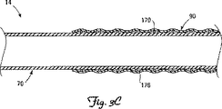
図2の実施形態においては、保護層90は、リード本体70上に配置されるポリマー製の被覆である。用いるポリマー材料は、所望する保護機能に応じて選択する。いくつかの実施形態では、保護層90は、ePTFE、ポリテトラフルオロエチレン(PTFE)、ポリエチレン、シリコーンゴム、ポリウレタン、及びこれらのポリマー等のポリマー材から完全に、もしくは実質的に形成される。一実施形態では、保護層90は、ポリウレタンをベースにしたポリマーから形成される。他の実施形態では、保護層90が、シリコーンポリウレタン共重合体から形成される。いくつかの実施形態では、保護層90が、ePTFE及び/又はPTFE等の滑らかな材料から形成される。これらの滑らかな材料は、耐摩耗性、及び高温や電気焼灼器による損傷に対する耐性に優れ、かつ、組織内殖及び繊維形成を抑制する機能を有する。また、所望する特定の特性をもたらすために他の材料を用いてもよい。
In the embodiment of FIG. 2, the
いくつかの実施形態では、保護層90は、各々所望する機能を供するために選択された複数のポリマー材を2層以上有する。例えば、一実施形態では、保護層90が、高温や電気焼灼器による損傷に対する耐性をもたらすシリコーンゴムの層を有し、その下に、高い耐磨耗性を供するポリウレタンの層を有する。他の実施形態では、複数のポリマー層の他の組み合わせを用いてよい。
In some embodiments, the
保護層90は、適宜なプロセスにより形成可能である。一実施形態では、保護層90は、リード本体70に巻回されたテープ又はリボンの形をとる。一実施形態では、保護層90は、リード本体70に巻回されたePTFE製のテープである。又は、いくつかの実施形態においては、保護層90は、ePTFE押出成形品又はPTFE押出成形品等のポリマー押出成形品であってもよい。保護層90は、リード本体70上に装着及び固着された独立した管状部材であってもよい。また、さらに他の実施形態では、ポリマー保護層90が、噴霧、蒸着、浸漬、又は他のコーティング処理により施されてもよい。つまり、保護層90の形成に用いる構造及びプロセスは限定されない。
The
いくつかの実施形態では、以下に詳細を示すとおり、保護層90が、上記のポリマー層に加えてさらに補強材(ワイヤ、編組等)を有する。これらの補強材は、基端領域76の耐破砕性及び全体的強度を向上させる。
In some embodiments, as will be described in detail below, the
図3Aは、本発明の一実施形態によるリード14の一部を示す概略断面図である。明瞭な図示を目的として、図3Aにおいては、ケーブルやコイル導体等の、リード14内部の特徴が省略されている。図3Aの実施形態では、保護層90がポリマー層156内に埋め込まれた補強用繊維編組150を有する。編組150は、耐破砕性、耐切創性、圧縮強度、引張強度等を向上させるために、所望する可撓性及び強度を有するよう構成される。いくつかの実施形態では、例えばシート状や管状の編組150がリード本体70上に配置され、ポリマー層156がリード本体70上の編組150の上にコーティングされる。したがって、編組150は、ポリマー層156内に埋め込まれる。また他の実施形態では、保護層90が、編組150及びポリマー層156を含む独立構造体として形成され、医療用接着剤やシュリンクラッピング等を用いた好適なプロセスによりリード本体70上に装着及び固定される。他の実施形態では、ポリマー層156がePTFE製やPTFE製のテープ又はリボンであり、そのポリマー層156自体が編組150で補強される。また、他の実施形態においては、他の構成を用いてよい。
FIG. 3A is a schematic cross-sectional view illustrating a portion of a lead 14 according to an embodiment of the present invention. For the purpose of clear illustration, in FIG. 3A, features inside the
図3Bは、本発明の別の実施形態によるリード14の一部を示す概略断面図である。明瞭な図示を目的として、図3Bにおいては、ケーブルやコイル導体等の、リード14内部の特徴が省略されている。図3Bの実施形態では、保護層90が、リード本体70に巻回され、かつポリマー層166内に埋め込まれた補強ワイヤ160を有する。図示された実施形態ではワイヤ160の断面は略円形であるが、他の実施形態では、偏平状等、他の形状のワイヤを使用してもよい。図3Aの実施形態と同様に、ワイヤ160は、耐破砕性、耐切創性、圧縮強度、引張強度等を向上させるために、所望する可撓性及び強度を有するよう構成される。いくつかの実施形態では、ワイヤ160がリード本体70に巻回され、ポリマー層166がリード本体70上のワイヤ160の上にコーティングされる。したがって、ワイヤ160は、ポリマー層166内に埋め込まれる。また他の実施形態では、保護層90がワイヤ160及びポリマー層166を含む独立構造として形成され、リード本体70上に装着及び固定される。他の実施形態では、ポリマー層166がePTFE製やPTFE製のテープ又はリボンであり、そのポリマー層166自体がワイヤ160で補強される。
FIG. 3B is a schematic cross-sectional view illustrating a portion of a lead 14 according to another embodiment of the present invention. For the purpose of clear illustration, in FIG. 3B, features inside the
図3A及び図3Bに示す実施形態において、編組150及び/又はワイヤ160は、耐破砕性や耐切創性をもたらす強度及び可撓性を所望の程度有するあらゆる材料で形成することが可能である。いくつかの実施形態では、ポリマー製や金属製のワイヤ及びファイバーが用いられる。いくつかの実施形態では、編組150又はワイヤ160が超弾性の金属又はポリマーから形成される。編組及びワイヤの金属材料の例としては、限定しないが、ステンレス鋼、MP35N、ニチノール等のニッケルチタン合金等が挙げられる。
In the embodiment shown in FIGS. 3A and 3B, the
図3Cは、本発明の別の実施形態によるリード14の一部を示す概略断面図である。明瞭な図示を目的として、図3Cにおいては、ケーブルやコイル導体等の、リード14内部の特徴が省略されている。図3Cの実施形態では、保護層90は、リード本体70に巻回され、かつポリマー層176により被覆されたワイヤ170を有する。この実施形態は、ワイヤ170がポリマー層176内に埋め込まれていないという点で、図3Bの実施形態と異なっている。この実施形態では、ポリマー層176は、ワイヤ170を覆うカバー層として機能する。いくつかの実施形態では、ポリマー層176がワイヤ170上に巻回されたテープ又はリボンであってもよいし、ワイヤ170上に装着された環状の構造であってもよい。若しくは、コーティングとしてワイヤ170上に施されてもよい。いくつかの実施形態では、図3Aの編組等の編組又はワイヤを、ワイヤ170と同様に用いて保護層90を補強してもよい。
FIG. 3C is a schematic cross-sectional view illustrating a portion of a lead 14 according to another embodiment of the present invention. For the purpose of clear illustration, in FIG. 3C, features inside the
当然ながら、いくつかの実施形態では、保護層90が1つ又は複数のポリマー層から形成され、補強用の編組やワイヤ等を含んでいない。
図4は、本発明の別の実施形態による他のリード214の一部を示す概略断面図である。明瞭な図示を目的として、図4においては、ケーブルやコイル導体等の、リード214内部の特徴が省略されている。リード214はあらゆる点でリード14に類似しており、可撓性及び絶縁性を有し、かつその一部で基端領域276を形成するリード本体270と、リード本体270上に配置された保護層290とを有する。この実施形態では、保護層290は、織編物又は編組であり、上記の実施形態と異なりポリマー層を有しない。一実施形態では、保護層290は、Kevlar(登録商標)の商品名で販売されている合成繊維編組等である。他の実施形態では、保護層290は、ポリマー製又は金属製の織編物、編組、又はコイルである。
Of course, in some embodiments, the
FIG. 4 is a schematic cross-sectional view showing a portion of another lead 214 according to another embodiment of the present invention. For the purpose of clear illustration, in FIG. 4, features inside the
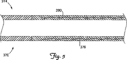
図5は、本発明の別の実施形態による他のリード314の一部を示す概略断面図である。明瞭な図示を目的として、図5においては、ケーブルやコイル導体等の、リード314内部の特徴が省略されている。リード314はあらゆる点でリード14に類似しており、可撓性及び絶縁性を有し、かつその一部で基端領域376を形成するリード本体370を有する。この実施形態では、リード本体370の基端領域376は保護層としても機能し、リード本体370内に一体に形成された保護要素390を有する。保護要素390は、上記の織編物、編組、ワイヤ、コイル等のいずれであってもよい。したがって、図5の実施形態では、リード本体370の外面上に独立した保護層が施されていないのにもかかわらず、リード本体370の少なくとも基端領域376は保護されることになる。この実施形態は、リード314において、保護された基端領域376と保護されていない領域が実質的に又は完全に等しい径を有することができるという利点を有する。
FIG. 5 is a schematic cross-sectional view showing a portion of another lead 314 according to another embodiment of the present invention. For the purpose of clear illustration, the internal features of the
図6は、本発明の別の実施形態によるリード414を示す斜視図である。リード414はあらゆる点で上記のリード14、214、314に類似しているか、又は同一であり、長尺状リード本体470及びリード本体470に接続された基端コネクタ472を備える。さらに、リード本体470は、基端領域476、中間領域484、及び先端領域488を有する。リード414は、リード本体470上にさらに保護層490を有する。前述の実施形態のリードと同様に、基端領域476は、植え込まれたパルス発生器12から延び、例えば左鎖骨下静脈40等の血管系に挿入され得る長さを有し、中間領域484は基端領域476から血管内を延びる。先端領域388は、リード414の心臓内領域となるよう構成され、心臓内を延びる。図に示されるように、リード414は、リード14の縫合スリーブ124に類似しているか、又は同一である縫合スリーブ492を備える。
FIG. 6 is a perspective view of a lead 414 according to another embodiment of the present invention. The
図6の実施形態では、保護層490がコネクタ472から先端領域488の基端側の端まで施されている。したがって、リード414の基端領域476と中間領域484の両方が保護層490で覆われている。この構成により、リード470の、縫合スリーブ492に覆われ、かつ血管への挿入部位54(図1参照)の近傍となる部分が保護される。このような実施形態のいくつかでは、保護層490がコネクタ472から始まり、リード414の先端チップから約25センチメートル基端側の位置まで施される。
In the embodiment of FIG. 6, the
リード414全般、特に保護層490は、上記の実施形態で挙げたいかなる構成を有していてもよい。図6の実施形態では、リード414は、固定用らせん体506及び複数のコイル電極512、518備える。本実施形態では、電極512、518は心臓に除細動を施すために衝撃を与える電極であり、組織内殖の調節(促進又は抑制)を目的としたコーティングを各々有する。一実施形態では、これらの電極は、ePTFEテープコーティングで覆われる。このような実施形態では、保護層490は、基端側電極418から基端コネクタ472に向かって基端側方向に覆い延びるePTFEテープにより少なくともその一部が形成される。又は、ePTFEテープ保護層390は、電極518上のePTFEカバーに連結される独立した構造としてもよい。当然ながら、他の実施形態においては、前述の他の保護層の構造を用いてよい。
The
図2〜6の実施形態のリードはすべて除細動刺激の伝達を目的とした電極を備えている。他の実施形態では、別の種類の植え込み型医療用電気リードが、上記のような保護領域を1つ又は複数有する。例えば、リードを保護するという前述の考え方は、右心房、右心室、左心室(図1参照)のいずれか1以上をペーシングするリードに応用することもできる。 The leads of the embodiments of FIGS. 2-6 all have electrodes intended for the transmission of defibrillation stimuli. In other embodiments, another type of implantable medical electrical lead has one or more protective areas as described above. For example, the above-described idea of protecting a lead can be applied to a lead that paces one or more of the right atrium, right ventricle, and left ventricle (see FIG. 1).
例えば、図7に示すのは、別の実施形態であり、両心室ペーシングや心臓再同期療法システム等において左心室のペーシングに適したリード614である。通常、このようなリードは、血管内を経て右心房及び冠状静脈洞(冠状静脈系から右心房に血液を流す大静脈)に入り、その後左心室壁近傍の冠状静脈に入るよう構成される。したがって、図7に示されるように、リード614は長尺状リード本体670、及びリード本体670に接続する基端コネクタ672を備える。リード本体670は基端領域676、中間領域684、及び先端領域688を含む。さらに、リード614は、リード本体670の基端領域676上に保護層690を含む。
For example, FIG. 7 shows another embodiment, which is a lead 614 suitable for left ventricular pacing, such as in a biventricular pacing or cardiac resynchronization therapy system. Typically, such leads are configured to enter the right atrium and coronary sinus (the vena cava that flows blood from the coronary venous system to the right atrium) through the blood vessel and then into the coronary vein near the left ventricular wall. Therefore, as shown in FIG. 7, the
上記の別のリード実施形態と同様に、基端領域676は、植え込まれたパルス発生器12から延び、血管への挿入部位54から先端側すぐに位置する左鎖骨下静脈40(図1)等の血管系内に挿入され得る長さを有する。したがって、リード14が植え込まれた状態では、基端領域676の大部分は皮下に位置し、端の部分は血管内に位置する。中間領域684は、基端領域676から、すなわち血管への挿入部位54の先端側すぐから血管内を延び、左鎖骨下静脈40及び左腕頭静脈52を介して上大静脈30に挿入される。先端領域688は、右心房24に入り、冠状静脈洞(図1には図示せず)を介して左心室近傍の冠状静脈内の所望する植え込み部位に挿入される。
Similar to the alternate lead embodiment described above, the
図7に示す実施形態では、先端領域688が一対のリング電極712、718を備える。これらの電極712、718は、心臓の電気的活動の感知や心臓組織への電気刺激の送達を行う。他の実施形態では、リード614は、2つよりも多い又は少ない電極を有する。リード614の先端領域688には、血管静脈系内において先端領域688が固定し易くなるように、予めらせん形状が形成されている。他の実施形態においては、予め形成された別の形状、歯、拡張型固定要素(ステント等)などの追加又は代替の固定手法を用いてもよい。
In the embodiment shown in FIG. 7, the tip region 688 includes a pair of ring electrodes 712, 718. These electrodes 712, 718 sense cardiac electrical activity and deliver electrical stimulation to cardiac tissue. In other embodiments, the
基端領域676は、その大部分が皮下に植え込まれるため、この領域の動作要件及び送達要件は、前述の他の実施形態におけるものと同様である。したがって、保護層690は、この領域の摩擦、破砕、切創、高温への耐性を高め、かつ/若しくは、基端領域676の強度及び耐久性を向上させるよう機能する。保護層690は、リード14、214、314及び414に関連して前述したいかなる形状で形成されていてもよい。図7の実施形態では、中間領域684及び先端領域688の強度及び可撓性が影響を受けないように、基端領域686のみが保護層690を有する。他の実施形態では、中間領域684と先端領域688のどちらか一方又は両方の全体若しくは一部に、基端領域676に加えて、若しくは基端領域676に代えて保護層が施されていてもよい。
Since the
本発明において以下の提案がなされる。
(提案1)
拍動管理システムにおいてパルス発生器に接続される医療用電気リードであって、
前記リードをパルス発生器に対して機械的及び電気的に接続する基端コネクタと、
可撓性を有し、かつ前記コネクタから先端方向に延びるとともに、基端領域と、中間領域と、先端チップで終結する先端領域とを形成するリード本体と、
前記リード本体の先端領域に接続された少なくとも1つの電極と、
前記少なくとも1つの電極をコネクタに電気的に接続するために少なくとも1つの電極からコネクタまで延びる少なくとも1つの導電体と、
少なくとも基端領域の耐摩耗性を強化及び向上させるべくリード本体の基端領域上に延び、かつリード本体の先端領域上には延びることがない保護手段とを備えるリード。
(提案2)
前記基端領域が、実質的に皮下に植え込まれ、かつパルス発生器の植え込み位置から、心臓血管系への挿入部位より先端側の位置まで延びる長さを有する提案1に記載のリード。
(提案3)
中間領域の耐摩耗性を強化及び向上させるための保護手段をさらに備える提案2に記載のリード。
(提案4)
拍動管理システムにおいてパルス発生器に接続される医療用電気リードであって、
前記リードをパルス発生器に対して機械的及び電気的に接続する基端コネクタと、
可撓性を有し、かつ前記コネクタから先端方向に延びるリード本体と、
前記リード本体は、
(1)皮下に植え込まれ、かつパルス発生器の植え込み位置から、心臓血管系への挿入部位より先端側の位置まで延びる長さを有する基端領域と、
(2)前記基端領域から、患者の心臓の上大静脈より先端側の位置まで先端方向に延びる長さを有する中間領域と、
(3)先端チップにおいて終結し、かつ患者の心臓内において前記中間領域から先端方向に延びる先端領域とを有することと、
リード本体の基端領域上及び中間領域上のみに配置され、かつ滑らかなポリマー材と該ポリマー材内に埋め込まれた補強材とを有するとともに、コネクタから先端方向に延び、かつリード本体の中間領域より基端側で終結する保護層と、
リード本体の先端領域に接続された少なくとも1つの電極と、
前記少なくとも1つの電極からコネクタまで延びて、同少なくとも1つの電極をコネクタに対して電気的に接続する少なくとも1つの導電体とを備えるリード。
本発明の範囲から逸脱することなく、説明された例示的な実施形態に種々の改変及び付加をなすことができる。たとえば、上述した実施形態は特定の特徴について言及しているが、本発明の範囲は、特徴のさまざまな組み合わせを有する実施形態、及び説明された特徴のすべてを含むわけではない実施形態も含む。したがって、本発明の範囲は、特許請求の範囲とそのすべての均等物に含まれるかかるすべての変更例を包含するものである。
The following proposals are made in the present invention.
(Proposal 1)
A medical electrical lead connected to a pulse generator in a pulsatile management system,
A proximal connector for mechanically and electrically connecting the lead to a pulse generator;
A lead body having flexibility and extending in a distal direction from the connector, and forming a proximal region, an intermediate region, and a distal region terminating in a distal tip;
At least one electrode connected to a tip region of the lead body;
At least one conductor extending from the at least one electrode to the connector to electrically connect the at least one electrode to the connector;
A lead that extends over the proximal end region of the lead body and does not extend over the distal end region of the lead body to enhance and improve at least the wear resistance of the proximal end region.
(Proposal 2)
The lead according to Proposition 1, wherein the proximal region is substantially subcutaneously implanted and has a length extending from the implantation position of the pulse generator to a distal position from the insertion site into the cardiovascular system.
(Proposal 3)
The lead according to
(Proposal 4)
A medical electrical lead connected to a pulse generator in a pulsatile management system,
A proximal connector for mechanically and electrically connecting the lead to a pulse generator;
A lead body having flexibility and extending in a distal direction from the connector;
The lead body is
(1) a proximal region that is implanted subcutaneously and has a length extending from the implantation position of the pulse generator to a distal position from the insertion site into the cardiovascular system;
(2) an intermediate region having a length extending in the distal direction from the proximal region to a position on the distal side from the superior vena cava of the patient's heart;
(3) having a distal end region terminating in the distal tip and extending distally from the intermediate region in the patient's heart;
The lead body is disposed only on the proximal end region and the intermediate region of the lead body, has a smooth polymer material and a reinforcing material embedded in the polymer material, extends from the connector in the distal direction, and is an intermediate region of the lead body. A protective layer that terminates more proximally,
At least one electrode connected to the tip region of the lead body;
And at least one conductor extending from the at least one electrode to the connector and electrically connecting the at least one electrode to the connector.
Various modifications and additions may be made to the described exemplary embodiments without departing from the scope of the present invention. For example, although the embodiments described above refer to particular features, the scope of the invention includes embodiments having various combinations of features, as well as embodiments that do not include all of the described features. Accordingly, the scope of the present invention is intended to embrace all such alterations that fall within the scope of the claims and all equivalents thereof.
Claims (13)
前記リードをパルス発生器に対して機械的及び電気的に接続する基端コネクタと、
可撓性を有し、かつ前記コネクタから先端方向に延びるとともに、
皮下の植え込み部位に植え込まれ、かつパルス発生器の植え込み位置から、心臓血管系への挿入部位より先端側の位置まで延びる長さを有する基端領域と、
基端領域から患者の心臓の上大静脈より先端側の位置まで先端方向に延びる長さを有する中間領域と、
先端チップで終結し、患者の心臓内において、中間領域から先端方向に延びる先端領域とを形成するリード本体と、
前記リード本体の基端領域上に配置され、かつリード本体の先端領域上には配置されることなく、更には耐摩耗性を有する滑らかな外面を有するポリマー材と、保護層内に配置された補強材とを有する保護層と、
前記リード本体の先端領域に接続されたコイル電極と、
心臓組織に貫入し、かつリード本体の先端チップから先端方向に延びる固定用らせん体を含むチップ電極と
コイル電極からコネクタまで延びる第1の導体と、
チップ電極からコネクタまで延びる第2の導体とを備えるリード。A medical electrical lead connected to a pulse generator in a pulsatile management system,
A proximal connector for mechanically and electrically connecting the lead to a pulse generator;
Having flexibility and extending from the connector in the distal direction,
A proximal region that is implanted into the subcutaneous implantation site and has a length that extends from the implantation location of the pulse generator to a location distal to the insertion site into the cardiovascular system ;
An intermediate region having a length extending in the distal direction from the proximal region to a position distal to the superior vena cava of the patient's heart ;
A lead body that terminates in a tip and forms a tip region extending distally from an intermediate region within the patient's heart ;
A polymer material having a smooth outer surface that is disposed on the proximal end region of the lead body and is not disposed on the distal end region of the lead body, and is further disposed in a protective layer. A protective layer having a reinforcing material;
A coil electrode connected to the tip region of the lead body ;
A tip electrode including a fixing helical body penetrating into the heart tissue and extending in a distal direction from the distal tip of the lead body;
A first conductor extending from the coil electrode to the connector;
And a second conductor extending from the chip electrode to the connector .
前記ポリマー材が編組上に配置される請求項1に記載のリード。The reinforcing material is a flexible braid disposed on the lead body,
The lead of claim 1, wherein the polymer material is disposed on a braid.
前記ポリマー材がコイル上に配置される請求項1に記載のリード。The reinforcing material is a wire or ribbon configured as a helical coil wound around a lead body;
The lead of claim 1, wherein the polymer material is disposed on a coil.
Applications Claiming Priority (3)
| Application Number | Priority Date | Filing Date | Title |
|---|---|---|---|
| US2899908P | 2008-02-15 | 2008-02-15 | |
| US61/028,999 | 2008-02-15 | ||
| PCT/US2009/034086 WO2009102974A1 (en) | 2008-02-15 | 2009-02-13 | Medical electrical lead with proximal armoring |
Publications (2)
| Publication Number | Publication Date |
|---|---|
| JP2011512200A JP2011512200A (en) | 2011-04-21 |
| JP5048849B2 true JP5048849B2 (en) | 2012-10-17 |
Family
ID=40566346
Family Applications (1)
| Application Number | Title | Priority Date | Filing Date |
|---|---|---|---|
| JP2010546925A Expired - Fee Related JP5048849B2 (en) | 2008-02-15 | 2009-02-13 | Medical electrical lead with proximal protection |
Country Status (4)
| Country | Link |
|---|---|
| US (1) | US8099175B2 (en) |
| EP (1) | EP2252364B1 (en) |
| JP (1) | JP5048849B2 (en) |
| WO (1) | WO2009102974A1 (en) |
Families Citing this family (23)
| Publication number | Priority date | Publication date | Assignee | Title |
|---|---|---|---|---|
| JP5232251B2 (en) * | 2008-02-15 | 2013-07-10 | カーディアック ペースメイカーズ, インコーポレイテッド | Modular zoned medical electrical lead design |
| US20110112614A1 (en) * | 2009-11-12 | 2011-05-12 | Joshua Haarer | Fiber reinforced silicone for cardiac and neurostimulation leads |
| US8618200B2 (en) | 2010-07-22 | 2013-12-31 | Biotronik Se & Co. Kg | Electrode lead for medical use, insulating tube and method for producing the same |
| US8986382B2 (en) * | 2011-05-03 | 2015-03-24 | Boston Scientific Neuromodulation Corporation | Tissue fixation and repair systems and methods |
| US9526887B2 (en) | 2012-06-29 | 2016-12-27 | Nuvectra Corporation | Method of making a braided lead with imbedded fixation structures |
| US8676347B2 (en) * | 2012-06-29 | 2014-03-18 | Greatbatch Ltd. | Braided lead with embedded fixation structures |
| US8644953B1 (en) | 2012-08-10 | 2014-02-04 | Greatbatch Ltd. | Lead with braided reinforcement |
| US9095700B2 (en) | 2012-08-10 | 2015-08-04 | Greatbach Ltd. | Lead positioning and fixation system |
| US9517334B2 (en) | 2013-08-19 | 2016-12-13 | Boston Scientific Neuromodulation Corporation | Lead anchors and systems and methods employing the lead anchors |
| US9636498B2 (en) | 2015-08-03 | 2017-05-02 | Boston Scientific Neuromodulation Corporation | Lead anchor with a wedge and systems using the lead anchor |
| US10071242B2 (en) | 2016-02-29 | 2018-09-11 | Boston Scientific Neuromodulation Corporation | Lead anchor for an electrical stimulation system |
| CN108883269B (en) * | 2016-03-31 | 2022-05-24 | 心脏起搏器股份公司 | Extraction device configured for extracting a chronically implanted medical device |
| WO2017201058A1 (en) | 2016-05-17 | 2017-11-23 | Boston Scientific Neuromodulation Corporation | Systems and methods for anchoring a lead for neurostimulation of a target anatomy |
| US10709886B2 (en) | 2017-02-28 | 2020-07-14 | Boston Scientific Neuromodulation Corporation | Electrical stimulation leads and systems with elongate anchoring elements and methods of making and using |
| US10835739B2 (en) | 2017-03-24 | 2020-11-17 | Boston Scientific Neuromodulation Corporation | Electrical stimulation leads and systems with elongate anchoring elements and methods of making and using |
| US10857351B2 (en) | 2017-04-28 | 2020-12-08 | Boston Scientific Neuromodulation Corporation | Lead anchors for electrical stimulation leads and systems and methods of making and using |
| WO2019036571A1 (en) | 2017-08-17 | 2019-02-21 | Cardiac Pacemakers, Inc. | Single incision subcutaneous implantable defibrillation system |
| US11116966B2 (en) | 2017-08-17 | 2021-09-14 | Cardiac Pacemakers, Inc. | Retention mechanism for an implantable lead |
| US10888697B2 (en) | 2017-08-18 | 2021-01-12 | Cardiac Pacemakers, Inc. | Fixation mechanism for an implantable lead |
| US10751526B2 (en) | 2017-10-25 | 2020-08-25 | Cardiac Pacemakers, Inc. | Subcutaneous lead implantation |
| US11147964B2 (en) | 2018-04-23 | 2021-10-19 | Cardiac Pacemakers, Inc. | Subcutaneous lead fixation member |
| US11219775B2 (en) | 2018-05-01 | 2022-01-11 | Cardiac Pacemakers, Inc. | Retention mechanism for an implantable lead |
| CN112469464B (en) | 2018-07-23 | 2024-07-26 | 心脏起搏器股份公司 | Retaining mechanism for implantable lead |
Family Cites Families (19)
| Publication number | Priority date | Publication date | Assignee | Title |
|---|---|---|---|---|
| US5246014A (en) | 1991-11-08 | 1993-09-21 | Medtronic, Inc. | Implantable lead system |
| US5231996A (en) | 1992-01-28 | 1993-08-03 | Medtronic, Inc. | Removable endocardial lead |
| US5358516A (en) | 1992-12-11 | 1994-10-25 | W. L. Gore & Associates, Inc. | Implantable electrophysiology lead and method of making |
| US5674272A (en) * | 1995-06-05 | 1997-10-07 | Ventritex, Inc. | Crush resistant implantable lead |
| US5845396A (en) | 1996-12-17 | 1998-12-08 | Pacesetter, Inc. | Co-radial, multi-polar coiled cable lead and method for making the same |
| US5917346A (en) | 1997-09-12 | 1999-06-29 | Alfred E. Mann Foundation | Low power current to frequency converter circuit for use in implantable sensors |
| US5931862A (en) * | 1997-12-22 | 1999-08-03 | Pacesetter, Inc. | Medical lead and method of making and using with sodium sulfosuccinic ester |
| US6717056B2 (en) | 2000-06-13 | 2004-04-06 | Hak Consulting, Llc | Fatigue-resistant conductive wire article |
| US6705900B2 (en) * | 2001-02-21 | 2004-03-16 | Medtronic, Inc. | Lead up-sizing sleeve |
| US20020188337A1 (en) | 2001-04-17 | 2002-12-12 | Bischoff Thomas C. | Apparatus for transferring traction forces exerted on an implantable medical lead |
| US7020529B2 (en) * | 2001-05-02 | 2006-03-28 | Gore Enterprise Holdings, Inc. | Defibrillation electrode cover |
| US7292894B2 (en) | 2002-09-27 | 2007-11-06 | Medtronic, Inc. | Methods and apparatus for joining small diameter conductors within medical electrical leads |
| US7590454B2 (en) | 2004-03-12 | 2009-09-15 | Boston Scientific Neuromodulation Corporation | Modular stimulation lead network |
| US7238883B2 (en) | 2004-08-11 | 2007-07-03 | Cardiac Pacemakers, Inc. | Lead assembly with flexible portions and method therefor |
| US7519432B2 (en) * | 2004-10-21 | 2009-04-14 | Medtronic, Inc. | Implantable medical lead with helical reinforcement |
| US7551967B1 (en) | 2005-05-19 | 2009-06-23 | Pacesetter, Inc. | Implantable medical leads and devices having carbon nanotube-based anti-electrostatic coatings and methods for making such leads and devices |
| US7366573B2 (en) | 2005-06-10 | 2008-04-29 | Cardiac Pacemakers, Inc. | Polymer lead covering with varied material properties |
| US7899555B2 (en) | 2006-04-11 | 2011-03-01 | Pacesetter, Inc. | Intrapericardial lead |
| JP5232251B2 (en) | 2008-02-15 | 2013-07-10 | カーディアック ペースメイカーズ, インコーポレイテッド | Modular zoned medical electrical lead design |
-
2009
- 2009-02-13 US US12/371,264 patent/US8099175B2/en not_active Expired - Fee Related
- 2009-02-13 WO PCT/US2009/034086 patent/WO2009102974A1/en not_active Ceased
- 2009-02-13 EP EP09710890A patent/EP2252364B1/en not_active Not-in-force
- 2009-02-13 JP JP2010546925A patent/JP5048849B2/en not_active Expired - Fee Related
Also Published As
| Publication number | Publication date |
|---|---|
| US20090210043A1 (en) | 2009-08-20 |
| WO2009102974A1 (en) | 2009-08-20 |
| JP2011512200A (en) | 2011-04-21 |
| US8099175B2 (en) | 2012-01-17 |
| EP2252364B1 (en) | 2012-06-20 |
| EP2252364A1 (en) | 2010-11-24 |
Similar Documents
| Publication | Publication Date | Title |
|---|---|---|
| JP5048849B2 (en) | Medical electrical lead with proximal protection | |
| AU2010263218B2 (en) | Medical device lead including a unifilar coil with improved torque transmission capacity and reduced MRI heating | |
| US8676347B2 (en) | Braided lead with embedded fixation structures | |
| JP5232251B2 (en) | Modular zoned medical electrical lead design | |
| EP2827944B1 (en) | Systems and methods for stimulation of vagus nerve | |
| US8825181B2 (en) | Lead conductor with pitch and torque control for MRI conditionally safe use | |
| US10518083B2 (en) | Lead with braided reinforcement | |
| US6580949B1 (en) | Implantable electrode lead | |
| US20140075753A1 (en) | Implantable leads with a conductor coil having two or more sections | |
| US8655458B2 (en) | Conformal electrodes for shaped medical device lead body segments | |
| US20070293925A1 (en) | Biasing and fixation features on leads | |
| WO2025022188A1 (en) | Transvenous intracardiac pacing catheter having improved leads | |
| US9775985B2 (en) | Braided lead with embedded fixation structures | |
| US20140135883A1 (en) | Detection/stimulation microlead with enhanced positioning |
Legal Events
| Date | Code | Title | Description |
|---|---|---|---|
| RD04 | Notification of resignation of power of attorney |
Free format text: JAPANESE INTERMEDIATE CODE: A7424 Effective date: 20120216 |
|
| TRDD | Decision of grant or rejection written | ||
| A01 | Written decision to grant a patent or to grant a registration (utility model) |
Free format text: JAPANESE INTERMEDIATE CODE: A01 Effective date: 20120710 |
|
| A01 | Written decision to grant a patent or to grant a registration (utility model) |
Free format text: JAPANESE INTERMEDIATE CODE: A01 |
|
| A61 | First payment of annual fees (during grant procedure) |
Free format text: JAPANESE INTERMEDIATE CODE: A61 Effective date: 20120719 |
|
| FPAY | Renewal fee payment (event date is renewal date of database) |
Free format text: PAYMENT UNTIL: 20150727 Year of fee payment: 3 |
|
| R150 | Certificate of patent or registration of utility model |
Ref document number: 5048849 Country of ref document: JP Free format text: JAPANESE INTERMEDIATE CODE: R150 Free format text: JAPANESE INTERMEDIATE CODE: R150 |
|
| R250 | Receipt of annual fees |
Free format text: JAPANESE INTERMEDIATE CODE: R250 |
|
| R250 | Receipt of annual fees |
Free format text: JAPANESE INTERMEDIATE CODE: R250 |
|
| R250 | Receipt of annual fees |
Free format text: JAPANESE INTERMEDIATE CODE: R250 |
|
| R250 | Receipt of annual fees |
Free format text: JAPANESE INTERMEDIATE CODE: R250 |
|
| R250 | Receipt of annual fees |
Free format text: JAPANESE INTERMEDIATE CODE: R250 |
|
| LAPS | Cancellation because of no payment of annual fees |