JP5045957B2 - Golf club shaft and grip - Google Patents
Golf club shaft and grip Download PDFInfo
- Publication number
- JP5045957B2 JP5045957B2 JP2009134799A JP2009134799A JP5045957B2 JP 5045957 B2 JP5045957 B2 JP 5045957B2 JP 2009134799 A JP2009134799 A JP 2009134799A JP 2009134799 A JP2009134799 A JP 2009134799A JP 5045957 B2 JP5045957 B2 JP 5045957B2
- Authority
- JP
- Japan
- Prior art keywords
- grip
- shaft
- tapered
- golf club
- concave groove
- Prior art date
- Legal status (The legal status is an assumption and is not a legal conclusion. Google has not performed a legal analysis and makes no representation as to the accuracy of the status listed.)
- Expired - Fee Related
Links
Images


Description
本発明は、ゴルフクラブのシャフトに、グリップの装着及び取り外し交換が簡単に出来る機能を、シャフトとグリップの双方に備えた、ゴルフクラブに関するものである。 The present invention relates to a golf club in which both the shaft and the grip have a function capable of easily mounting and removing the grip on the shaft of the golf club.
従来のゴルフクラブのシャフトとグリップは、両面テープや接着剤等でシャフトに強固に固定されているため、グリップ交換をするためにはカッター等でグリップを切開し、強固に接着固定されているシャフトよりグリップを剥ぎ取る作業も大変であり不便であった。 Since the shaft and grip of a conventional golf club are firmly fixed to the shaft with double-sided tape or adhesive, the shaft is firmly bonded and fixed by cutting the grip with a cutter or the like to replace the grip The work of stripping off the grip was also difficult and inconvenient.
個人でグリップ交換をする際に、両面テープや接着剤を付けたシャフトにグリップを挿入させる作業には、相当な熟練した交換技術を必要とし不便であった。 When exchanging grips by individuals, the work of inserting the grips into the shaft with double-sided tape or adhesive requires a considerable skill of exchanging technique and is inconvenient.
また、グリップの交換後は風通しの良い場所に24時間以上放置して、シャフトにグリップを完全に定着させてからでないとゴルフクラブの使用が出来ない等、不便であった。 Further, after replacing the grip, it was inconvenient that the golf club could not be used unless it was left in a well-ventilated place for 24 hours or more and the grip was completely fixed on the shaft.
従来のゴルフクラブをゴルフバッグ(キャディーバッグ)より出し入れする場合、ゴルフクラブ同士が絡み合い、また、グリップ同士が引っかかり合い、ゴルフバッグ(キャディーバッグ)からのクラブの出し入れがスムーズに出来ず大変に不便であった。 When a conventional golf club is taken in and out of a golf bag (caddy bag), the golf clubs are entangled with each other, and grips are caught between each other. there were.
従来のゴルフクラブ用グリップには、グリップ内径部に凸部を施したものがある。(特許文献1、2参照)
また、シャフトとヘッド部の交換が容易に出来る方法として、特許文献3に記載のものがある。
従来のゴルフクラブのシャフトとグリップは、両面テープや接着剤等でシャフトに強固に固定されているため、グリップ交換をするためにはカッター等でグリップを切開し、強固に接着固定されているシャフトよりグリップを剥ぎ取る作業も大変であり、シャフトよりグリップの交換がスムーズに行えないなど欠点があった。 Since the shaft and grip of a conventional golf club are firmly fixed to the shaft with double-sided tape or adhesive, the shaft is firmly bonded and fixed by cutting the grip with a cutter or the like to replace the grip The work of stripping off the grip was also difficult, and there was a drawback that the grip could not be exchanged smoothly from the shaft.
本発明は、このような点に鑑みて成されたものであり、その目的は従来のゴルフクラブでは成し得なかったゴルフクラブのシャフトからグリップの着脱交換が簡単に出来、且つ、ゴルフバッグ(キャディーバッグ)からのゴルフクラブの出し入れが容易に行えるように解決することである。 The present invention has been made in view of the above points. The object of the present invention is to easily attach and detach a grip from a shaft of a golf club, which cannot be achieved by a conventional golf club, It is to solve the problem so that the golf club can be easily taken in and out of the caddy bag.
上記課題を解決するために、本発明は、ゴルフクラブのシャフト及びグリップにおいて、シャフトは、グリップが装着される部分のシャフトの外径が、シャフトのグリップエンド側を細く、ヘッド部側に向けて太くなるテーパ形状とし、グリップの長さと略同等の長さの凹型溝をグリップが装着される部分のシャフト外周面長手方向部分に備え、前記凹型溝はシャフトのグリップエンド側の幅を広く、ヘッド部側に向けて幅が狭くなるテーパ形状を有し、グリップは前記凹型溝に嵌合するテーパ状凸型突起部を内周面長手方向に有することを特徴とする。In order to solve the above-described problems, the present invention provides a golf club shaft and grip, wherein the shaft has an outer diameter of a portion to which the grip is attached and a grip end side of the shaft is narrowed toward a head portion side. It has a tapered shape that is thicker, and has a concave groove with a length approximately equal to the length of the grip in the longitudinal direction of the shaft outer peripheral surface of the part where the grip is mounted. The grip has a tapered shape with a width narrowing toward the part side, and the grip has a taper-shaped convex protrusion fitted in the concave groove in the longitudinal direction of the inner peripheral surface.
ゴルフクラブのシャフト、及び、グリップの双方に着脱を容易に行える機能としてシャフトにテーパ状凹型溝を備え、グリップにテーパ状凸型突起部を備えたことに依り、いつでも、どこででも、誰にでも、簡単にシャフトよりグリップの着脱交換が自由に行えるゴルフクラブである。 As a function that can be easily attached to and detached from both the golf club shaft and the grip, the shaft has a tapered concave groove, and the grip has a tapered convex protrusion. It is a golf club in which grips can be easily attached and detached from the shaft.
シャフトからグリップの着脱交換が自由に出来るため、イニシャルや好みの柄などを付けたマイグリップや握力の弱い方にあっては、グリップの太さを自分の握力に合わせたマイグリップを作ることに依り、使用者にとってはいろいろな楽しみ方が期待出来る。 Since the grip can be freely attached and removed from the shaft, if you have a weak or weak grip with your initial handle or your favorite pattern, make a grip that matches the grip strength of your grip. Therefore, various ways of enjoying can be expected for the user.
従来のゴルフクラブをゴルフバッグ(キャディーバッグ)から出し入れする場合、ゴルフクラブ同士が絡み合い、また、グリップ同士が引っかかり合い、ゴルフバッグ(キャディーバッグ)からクラブの出し入れが大変であったが、本発明のゴルフクラブはシャフトよりグリップを外した状態でゴルフバッグ(キャディーバッグ)に収納出来るためゴルフクラブ同士の引っかかり合いも無くなり、ゴルフバッグ(キャディーバッグ)よりゴルフクラブの出し入れが容易である。 When a conventional golf club is taken in and out of a golf bag (caddy bag), the golf clubs are entangled with each other, grips are caught together, and it is difficult to put in and out of the golf bag (caddy bag). Since the golf club can be stored in the golf bag (caddy bag) with the grip removed from the shaft, the golf clubs are not caught between the golf clubs, and the golf club can be easily put in and out of the golf bag (caddy bag).
ゴルフクラブ用ヘッド部のホーゼルにゴルフクラブのシャフトを装着するための機能として、凹型溝、乃至、凸型突起部の機能をヘッド部ホーゼルに備えることに依り、ヘッド部、シャフト部、グリップ部の各部分が分離出来るためコンパクトな収納が可能になり、ゴルフバッグ(キャディーバッグ)のスリム化が期待できる。 As a function for mounting the golf club shaft on the hosel of the golf club head part, the head part hosel has the function of a concave groove or convex projection part. Since each part can be separated, compact storage is possible, and slimming of a golf bag (caddy bag) can be expected.
ゴルフクラブのシャフトにグリップを取り着けるシャフト端部外径部分の外周面に、グリップの長さと同等程度の長さ分の凹型の溝を備え、その窪んだ凹型の溝の両側の側壁部をテーパ状にして、また、グリップの内径円周面にグリップの長さと同等程度の長さ分のテーパ状の凸型突起部を備え、シャフトのテーパ状凹型溝へグリップのテーパ状凸型突起部部分を挿入させることにより、挿入終了点でシャフトとグリップ双方の凹凸部のテーパ部を合致させ、シャフトに備えた固定止めネジ用の雌ネジ部に固定止めネジを装着固定させることに依り安全に、且つ、機能的に使用が出来るゴルフクラブである。 The outer peripheral surface of the outer diameter part of the shaft end that attaches the grip to the shaft of the golf club is provided with a concave groove equivalent to the length of the grip, and the side walls on both sides of the concave groove are tapered. In addition, the tapered inner surface of the grip is provided with a tapered convex protrusion corresponding to the length of the grip, and the tapered convex protrusion portion of the grip is inserted into the tapered concave groove of the shaft. By inserting the, the taper part of the uneven part of both the shaft and the grip is matched at the insertion end point, and it is safe by attaching and fixing the fixing screw to the female screw part for the fixing screw provided in the shaft, And it is a golf club which can be used functionally.
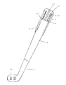
図1はゴルフクラブの全体図、乃至、グリップ部構成の断面説明図である。FIG. 1 is an overall view of a golf club or a cross-sectional explanatory view of a grip portion configuration.
図1において、シャフト1は、ゴルフクラブにグリップ2を装着するシャフト1の外径部分に、そのグリップ2を挿入するシャフト1の端部よりヘッド部16側に向け、そのシャフト1の外径部分をグリップ2の長さと同等程度分の長さ分をテーパ状にしたシャフトである。In FIG. 1, the
また、前記シャフト1の外径部分のテーパ形状は、シャフト1のグリップ2挿入口側端部を細く、ヘッド部16側に向け太くする形状である。The tapered shape of the outer diameter portion of the
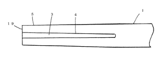
図3はシャフト外周面にテーパ状凹型溝を備えたシャフトの説明図である。FIG. 3 is an explanatory view of a shaft provided with a tapered concave groove on the outer peripheral surface of the shaft.
図4は図3に記載の、シャフトの断面説明図である。FIG. 4 is a cross-sectional explanatory view of the shaft shown in FIG.
これらの図において、前記シャフト1のテーパ部分にグリップ2を装着するシャフト1外径部分のテーパ状外周面5に、シャフト端部側19からヘッド部16側に向けて、グリップ2の長さと同等程度分の長さのテーパ状凹型溝3を備え、その窪んだテーパ状凹型溝3の両側の側壁部4をテーパ状にしたゴルフクラブのシャフトである。In these drawings, the length of the
前記シャフト1のテーパ状凹型溝3の側壁部のテーパ形状は、シャフト端部19のグリップ挿入口部分の幅を広く、シャフト1のヘッド部16側に向けて幅が狭くなるテーパ形状である。The tapered shape of the side wall portion of the tapered
テーパ状凹型溝3のテーパ部の長さは、概ねグリップの長さと同等程度の26cm〜27cm程度の長さである。The length of the tapered portion of the tapered
図9はグリップの内径部にテーパ状凸型突起部を備えたグリップの説明図である。FIG. 9 is an explanatory view of a grip provided with a tapered convex protrusion on the inner diameter portion of the grip.
図9において、前記シャフト用グリップ2の内径円周面にグリップ2の長さと同等程度の長さ分の、テーパ状凸型突起部6を備えたゴルフクラブ用のグリップである。In FIG. 9, the golf club grip is provided with a
グリップ内径円周面のテーパ状凸型突起部6のテーパ形状は、シャフト1への挿入口側のテーパ状凸型突起部側壁部分の幅を狭く、グリップエンド部23側に向け、テーパ状凸型突起部6の側壁部の幅が広くなるテーパ形状である。The taper shape of the
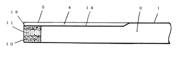
図2はシャフト端部の内径部に、グリップの固定止めネジ用の雌ネジ部を備えたシャフトの断面説明図である。FIG. 2 is a cross-sectional explanatory view of a shaft provided with an internal thread portion for a grip fixing screw at an inner diameter portion of the shaft end portion.
図5はシャフト端部の内径部に固定止めネジ用の雌ネジ部を備えたシャフトの断面説明図である。FIG. 5 is a cross-sectional explanatory view of a shaft provided with a female screw portion for a fixing set screw in the inner diameter portion of the shaft end portion.
図6は図5に記載のシャフトに、テーパ状凸型突起部を備えたグリップを装着したシャフトとグリップの断面説明図である。FIG. 6 is a cross-sectional explanatory view of a shaft and a grip in which a grip provided with a tapered convex protrusion is attached to the shaft shown in FIG.
図7は図6に記載の、シャフトの雌ネジ部の説明図である。FIG. 7 is an explanatory view of the female thread portion of the shaft shown in FIG.
図8は図6に記載のシャフトに、グリップの固定止めネジを装着した状態の断面説明図である。FIG. 8 is a cross-sectional explanatory view of a state where a grip fixing screw is attached to the shaft shown in FIG.
図13はシャフトにグリップを固定させる、固定止めネジの断面説明図である。FIG. 13 is a cross-sectional explanatory view of a fixing set screw for fixing the grip to the shaft.
これらの図において、テーパ状凹型溝3のついたシャフト1に、テーパ状凸型突起部6のついたグリップ2をシャフト1の端部側より挿入させシャフト1とグリップ2を合致、固定させ、且つ、シャフト1よりグリップ2が抜け出すのを防止するための固定止めネジ12用の雌ネジ部10を、グリップ2を挿入するシャフト端部19の内径部に備えたシャフトである。In these drawings, the
シャフト端部19の内径部に備えられているグリップ2の固定止めネジ12用雌ネジ部10の長さは、概ね1cm〜1.5cm程度で十分である。The length of the
ゴルフクラブ用シャフトのテーパ状凹型溝3へグリップ2のテーパ状凸型突起部6を挿入させることにより、シャフトの凹型溝3についているテーパと、グリップ2の内径円周面についている凸型突起部6のテーパがシャフト1へのグリップ2を挿入終了点で双方の凹凸部のテーパが合致し、グリップエンド部23の端部分を固定止めネジ12で圧着させシャフト1とグリップ2が固定されるため、使用中にシャフト軸とグリップが回転することがなく、安全に使用出来るようにしたゴルフクラブである。By inserting the
グリップ2を装着したシャフト端部19の内径部に備えた雌ネジ部10に固定止めネジ12を取り着けた後、固定止めネジ12が緩みシャフト1の雌ネジ部10より固定止めネジ12の離脱や事故などを防止するため、固定止めネジ12用の雄ネジ部13の長さを概ね1.5cm〜2.0cmと長めにすることで、固定止めネジ12が離脱する不測の事故が起きないようにした固定止めネジである。After attaching the fixing screw 12 to the
シャフト端部19の雌ネジ部10に着けた固定止めネジ12の緩みの程度にもよるが、グリップ2と固定止めネジ12の接する部分が5ミリ程度の緩んだ隙間が開くとグリップ2とシャフト1が固定されていないため、グリップ2とシャフト1間の遊びに使用者が気づくことにより、再度固定止めネジ12を締め直しすることに依り事故防止が出来る。Depending on the degree of looseness of the fixing screw 12 attached to the female threaded
グリップエンド部23側のグリップ輪切り断面の肉厚部分を固定止めネジ12が緩むのを防止するための、グリップ輪切り断面一周3波程度のゆるやかな波状の起伏をつけたグリップである。This grip is provided with a gentle wave-like undulation of about 3 waves around the grip ring section to prevent the fixing screw 12 from loosening the thick part of the grip ring section at the grip end portion 23 side.
グリップエンド部23側のグリップ輪切り断面の肉厚部分と接する固定止めネジ12側の接触面の部分に、固定止めネジ12が緩むのを防止するための接触面一周3波程度のゆるやかな波状の起伏にした固定止めネジである。On the contact surface portion on the fixing screw 12 side that is in contact with the thick portion of the grip ring section on the grip end portion 23 side, a gentle wave shape of about 3 waves around the contact surface to prevent the fixing screw 12 from loosening. It is a fixed set screw that is undulated.
図10はグリップの内径部にテーパ状多角形面を備えたグリップの説明図であるFIG. 10 is an explanatory diagram of a grip having a tapered polygonal surface on the inner diameter portion of the grip.
図11はテーパ状シャフトの外径面にテーパ状多角形面、乃至、シャフト端部に固定止めネジ用雌ネジ部を備えたシャフトの説明図である。FIG. 11 is an explanatory view of a shaft provided with a tapered polygonal surface on the outer diameter surface of the tapered shaft or a female screw portion for a fixing set screw at the shaft end portion.
図12は図11に記載のシャフトに、図10のグリップを装着した状態の断面説明図である。12 is an explanatory cross-sectional view of the shaft shown in FIG. 11 with the grip shown in FIG. 10 attached thereto.
ゴルフクラブにグリップ2を装着するシャフト端部19外径部分の外周面を、グリップ2の長さと同等程度の長さ分の五角形、乃至、六角形の多角形の外周面7にしたゴルフクラブのシャフトである。A golf club having an outer peripheral surface of an outer diameter portion of a
前記シャフト1の多角形の外周面7をテーパ状にしたゴルフクラブのシャフトである。This is a golf club shaft in which the polygonal outer
前記シャフトの多角形外周面7のテーパ形状は、グリップ2を挿入するシャフト1の端側を細く、シャフト1のヘッド部16側に向け太くしたテーパである。The taper shape of the polygonal outer
前記シャフトに装着するグリップの多角形の内周面8を、前記シャフト1と同様の五角形、乃至、六角形の多角形の形状面にしたゴルフクラブのグリップである。This is a golf club grip in which the polygonal inner
シャフト1のヘッド部16側、乃至、シャフト1のグリップ2側の双方に凹型溝又は多角形の形状の機能をシャフトの外径部分に備えることに依り、ヘッド部、シャフト部、グリップ部の着脱交換が容易になり、各部を使用者自身のフィーリングに合わせた自由な組み合わせが出来るゴルフクラブである。The head portion, shaft portion, and grip portion can be attached and detached by providing the outer diameter portion of the shaft with a concave groove or polygonal function on both the head portion 16 side of the
グリップ内周面15に備えた、凸型突起部6の突き出た凸部の高さはグリップ内周面15より2mm程度の高さを有し、そのグリップ内周面15より突き出た凸部分の幅は2mm〜3.5mm程度の範囲内のテーパ状凸型突起部である。The height of the protruding portion of the protruding
グリップを装着するシャフト1のテーパ状外周面5の外周面部分に備えたテーパ状凹型溝3の深さは、シャフト1のテーパ状外周面5より2.5mm程度の深さを有し、その溝幅は3.5mm〜2mm程度の範囲内のテーパ状凹型溝である。The depth of the tapered
シャフト1のテーパ状外周面5に備えたテーパ状凹型溝3の形状、乃至、グリップ内径面15に備えた凸型突起部6凸部分の形状は四角形の形状である。The shape of the tapered
テーパ状凸型突起部6を備えたグリップ2をシャフト1のテーパ状凹型溝3に挿入、シャフト1、グリップ2双方の凹凸部が合致した時点で、テーパ状凹型溝3の溝底部14とグリップ内径面15の凸型突起部6の突き出た凸部分が直接、接することのないよう双方の間に少なくとも0.5mm程度の隙間があり、テーパ状凹型溝3の溝底部14と凸型突起部6の突き出た凸部分が直接、接しない構成である。The
テーパ状凸型突起部6を備えたグリップ2をシャフト1のテーパ状凹型溝3に挿入、シャフト1、グリップ2双方の凹凸部を合致させた状況でグリップ2の外径表面上に捻れや起伏等の変化が生じない構造である。The
シャフト1のテーパ状凹型溝3にテーパ状凸型突起部6のついたグリップ2をシャフト1に挿入装着し、ゴルフクラブを使用する際に、凹凸双方の合致している機能部が合致点から外れたり、シャフト1とグリップ2が固定されずに回転等の状況が起きることのない充分な深さのテーパ状凹型溝3とテーパ状凸型突起部6の凸部の高さが充分な高さと強度を有した機能である。When the
ゴルフクラブ用グリップ2本体の内径孔15は、シャフト1へのグリップ2の挿入口側からグリップエンド部23まで、グリップ2本体の中芯軸を素通しに貫通した筒状である。The inner diameter hole 15 of the
テーパ状凹型溝3のシャフト1に、テーパ状凸型突起部6のついたグリップ2を挿入させ、双方の合致した凹凸の側壁部が使用時に於いて、合致した凹凸部が外れたり、グリップ2に変形が生じない強度を有した構成である。The
本発明の機能を活用することに依り、シャフトへのグリップの交換が容易にできるようになり、使用者にとっての利用範囲の広がりが期待できる。 By utilizing the function of the present invention, it becomes possible to easily exchange the grip to the shaft, and the use range for the user can be expected to be widened.
また、本発明の機能を活用することに依り、ゴルフバッグ(キャディーバッグ)への収納や取り出しが容易になり、ゴルフバッグ(キャディーバッグ)のスリム化が期待できる。 Further, by utilizing the function of the present invention, the golf bag (caddy bag) can be easily stored and taken out, and a slim golf bag (caddy bag) can be expected.
1 シャフト
2 グリップ
3 テーパ状凹型溝
4 側壁部
5 テーパ状外周面
6 テーパ状凸型突起部
7 多角形の外周面
8 多角形の内周面
9 シャフトの内径部
10 雌ネジ部
11 雌ネジ
12 固定止めネジ
13 雄ネジ部
14 溝底部
15 グリップ内周面
16 ヘッド部
17 テーパ部
18 固定止めネジ部のマーカ用の孔
19 シャフト端部
20 固定止めネジのグリップを圧着する面
21 シャフトのテーパ状多角形外周面
22 クリップのシャフトへの挿入口
23 グリップエンド部
DESCRIPTION OF
Claims (1)
Priority Applications (1)
| Application Number | Priority Date | Filing Date | Title |
|---|---|---|---|
| JP2009134799A JP5045957B2 (en) | 2009-06-04 | 2009-06-04 | Golf club shaft and grip |
Applications Claiming Priority (1)
| Application Number | Priority Date | Filing Date | Title |
|---|---|---|---|
| JP2009134799A JP5045957B2 (en) | 2009-06-04 | 2009-06-04 | Golf club shaft and grip |
Publications (3)
| Publication Number | Publication Date |
|---|---|
| JP2010279528A JP2010279528A (en) | 2010-12-16 |
| JP2010279528A5 JP2010279528A5 (en) | 2012-07-12 |
| JP5045957B2 true JP5045957B2 (en) | 2012-10-10 |
Family
ID=43536873
Family Applications (1)
| Application Number | Title | Priority Date | Filing Date |
|---|---|---|---|
| JP2009134799A Expired - Fee Related JP5045957B2 (en) | 2009-06-04 | 2009-06-04 | Golf club shaft and grip |
Country Status (1)
| Country | Link |
|---|---|
| JP (1) | JP5045957B2 (en) |
Families Citing this family (1)
| Publication number | Priority date | Publication date | Assignee | Title |
|---|---|---|---|---|
| JP6532216B2 (en) * | 2014-11-11 | 2019-06-19 | 三貴ホールディングス株式会社 | Grip mounting structure |
-
2009
- 2009-06-04 JP JP2009134799A patent/JP5045957B2/en not_active Expired - Fee Related
Also Published As
| Publication number | Publication date |
|---|---|
| JP2010279528A (en) | 2010-12-16 |
Similar Documents
| Publication | Publication Date | Title |
|---|---|---|
| JP2008149141A5 (en) | ||
| USD487493S1 (en) | Portion of a golf club head | |
| US8800614B2 (en) | Golf club head covers with a strap and methods to manufacture golf club head covers | |
| USD444834S1 (en) | Grooved end cap grip for a lacrosse stick | |
| JP5045957B2 (en) | Golf club shaft and grip | |
| JP2010178865A (en) | Skipping rope | |
| JP2010279528A5 (en) | ||
| TW201603971A (en) | Anti-detachment tool holder | |
| USD430248S (en) | Golf club shaft | |
| USD488202S1 (en) | Golf putter grip | |
| JP2000093569A (en) | Structure for connecting head and shaft of gate ball stick | |
| JP4125654B2 (en) | fishing rod | |
| JP2007185252A (en) | Grip for golf club | |
| JP6371598B2 (en) | Golf club | |
| JP3143187U (en) | Connecting / disconnecting structure to / from electric rotating tool mounting bit | |
| USD946100S1 (en) | End cap for golf club grip | |
| JPH0338112Y2 (en) | ||
| JP6147662B2 (en) | fishing rod | |
| JP3224968U (en) | String case | |
| JP3055403U (en) | RCA plug for audio | |
| JP2006136745A (en) | Mouth piece for medicinal bottle | |
| KR100837664B1 (en) | A button having thread | |
| JP3160250U (en) | wrench | |
| JP3122162U (en) | Improved structure of combination in interdental brush | |
| KR101790886B1 (en) | Dental instrument for removing crown |
Legal Events
| Date | Code | Title | Description |
|---|---|---|---|
| A521 | Request for written amendment filed |
Free format text: JAPANESE INTERMEDIATE CODE: A523 Effective date: 20120525 |
|
| A621 | Written request for application examination |
Free format text: JAPANESE INTERMEDIATE CODE: A621 Effective date: 20120525 |
|
| A871 | Explanation of circumstances concerning accelerated examination |
Free format text: JAPANESE INTERMEDIATE CODE: A871 Effective date: 20120525 |
|
| TRDD | Decision of grant or rejection written | ||
| A975 | Report on accelerated examination |
Free format text: JAPANESE INTERMEDIATE CODE: A971005 Effective date: 20120613 |
|
| A01 | Written decision to grant a patent or to grant a registration (utility model) |
Free format text: JAPANESE INTERMEDIATE CODE: A01 Effective date: 20120626 |
|
| A01 | Written decision to grant a patent or to grant a registration (utility model) |
Free format text: JAPANESE INTERMEDIATE CODE: A01 |
|
| A61 | First payment of annual fees (during grant procedure) |
Free format text: JAPANESE INTERMEDIATE CODE: A61 Effective date: 20120703 |
|
| FPAY | Renewal fee payment (event date is renewal date of database) |
Free format text: PAYMENT UNTIL: 20180727 Year of fee payment: 6 |
|
| R150 | Certificate of patent or registration of utility model |
Ref document number: 5045957 Country of ref document: JP Free format text: JAPANESE INTERMEDIATE CODE: R150 Free format text: JAPANESE INTERMEDIATE CODE: R150 |
|
| R250 | Receipt of annual fees |
Free format text: JAPANESE INTERMEDIATE CODE: R250 |
|
| LAPS | Cancellation because of no payment of annual fees |