JP5043473B2 - Viewfinder optical system and imaging apparatus using the same - Google Patents
Viewfinder optical system and imaging apparatus using the same Download PDFInfo
- Publication number
- JP5043473B2 JP5043473B2 JP2007051575A JP2007051575A JP5043473B2 JP 5043473 B2 JP5043473 B2 JP 5043473B2 JP 2007051575 A JP2007051575 A JP 2007051575A JP 2007051575 A JP2007051575 A JP 2007051575A JP 5043473 B2 JP5043473 B2 JP 5043473B2
- Authority
- JP
- Japan
- Prior art keywords
- lens
- mirror
- optical system
- image
- finder
- Prior art date
- Legal status (The legal status is an assumption and is not a legal conclusion. Google has not performed a legal analysis and makes no representation as to the accuracy of the status listed.)
- Expired - Fee Related
Links
Images


Classifications
-
- G—PHYSICS
- G03—PHOTOGRAPHY; CINEMATOGRAPHY; ANALOGOUS TECHNIQUES USING WAVES OTHER THAN OPTICAL WAVES; ELECTROGRAPHY; HOLOGRAPHY
- G03B—APPARATUS OR ARRANGEMENTS FOR TAKING PHOTOGRAPHS OR FOR PROJECTING OR VIEWING THEM; APPARATUS OR ARRANGEMENTS EMPLOYING ANALOGOUS TECHNIQUES USING WAVES OTHER THAN OPTICAL WAVES; ACCESSORIES THEREFOR
- G03B13/00—Viewfinders; Focusing aids for cameras; Means for focusing for cameras; Autofocus systems for cameras
- G03B13/02—Viewfinders
- G03B13/06—Viewfinders with lenses with or without reflectors
Landscapes
- Physics & Mathematics (AREA)
- General Physics & Mathematics (AREA)
- Lenses (AREA)
- Viewfinders (AREA)
Description
本発明は、観察倍率が大きくファインダー像を良好に観察することができるファインダー光学系に関し、特に一眼レフカメラ等の撮像装置に好適なものである。 The present invention relates to a finder optical system that can observe a finder image favorably with a large observation magnification, and is particularly suitable for an imaging apparatus such as a single-lens reflex camera.
従来、一眼レフカメラでは撮影レンズによって、焦点板上に形成したファインダー像(物体像)をファインダー光学系を介して観察している。このファインダー光学系は、焦点板上に形成されたファインダー像をペンタプリズム等の像反転手段を介して正立像とした後、接眼レンズによって拡大して観察するように構成されている。 Conventionally, in a single-lens reflex camera, a finder image (object image) formed on a focusing screen is observed by a photographic lens through a finder optical system. This finder optical system is configured to make a finder image formed on a focusing screen an erect image through an image inverting means such as a pentaprism, and then to enlarge and observe it with an eyepiece.
このようなファインダー光学系に用いられる接眼レンズには、高い観察倍率を有すること、十分な長さのアイレリーフがあること、視度調節機能があること、そして高い光学性能を有すること等が求められている。 An eyepiece used in such a viewfinder optical system is required to have a high observation magnification, a sufficiently long eye relief, a diopter adjustment function, and a high optical performance. It has been.
一般にこのようなファインダー光学系において、観察倍率は撮影レンズと接眼レンズの焦点距離の比で求められる。このため観察倍率を大きくする為には、接眼レンズの焦点距離を短くすることが必要となる。 In general, in such a finder optical system, the observation magnification is obtained by the ratio of the focal lengths of the taking lens and the eyepiece. For this reason, in order to increase the observation magnification, it is necessary to shorten the focal length of the eyepiece.
しかしながら一眼レフカメラのファインダー光学系においては、一般に視度を−1ディオプトリー付近に設定することが必要となる。このため、物体像が形成される焦点板から接眼レンズまでの距離(接眼レンズの主点位置までの光路長)によって接眼レンズの焦点距離は実質的に決定される。 However, in a finder optical system of a single-lens reflex camera, it is generally necessary to set the diopter near -1 diopter. Therefore, the focal length of the eyepiece is substantially determined by the distance from the focusing screen on which the object image is formed to the eyepiece (the optical path length to the main point position of the eyepiece).
従って一眼レフカメラにおいてファインダー光学系の観察倍率を大きくするにはペンタプリズムの光路長を短くし、接眼レンズをペンタプリズムになるべく近接させて配置するのが良い。 Therefore, in order to increase the observation magnification of the finder optical system in a single-lens reflex camera, it is preferable to shorten the optical path length of the pentaprism and place the eyepiece as close as possible to the pentaprism.
しかしながら、このような構成にすると、ファインダー光学系の観察部(アイポイント)がカメラの後面より物体側(ペンタプリズム側)に移動してしまい、実質的にアイレリーフが短くなってくる。 However, with such a configuration, the observation unit (eye point) of the finder optical system moves from the rear surface of the camera to the object side (penta prism side), and the eye relief is substantially shortened.
尚、ここでアイレリーフとは接眼レンズの射出面から観察者の瞳孔(アイポイント)までの距離である。 Here, eye relief is the distance from the exit surface of the eyepiece to the observer's pupil (eye point).
一方、カメラの軽量化及び簡素化(低コスト化)のため像反転手段としてペンタプリズムの替りにミラーを組み合わせた、所謂ペンタダハミラーを用いたファインダー光学系が種々と提案されている。 On the other hand, various finder optical systems using so-called penta roof mirrors that combine mirrors instead of penta prisms as image reversing means have been proposed in order to reduce the weight and simplify the camera (cost reduction).
このペンタダハミラーを用いたファインダー光学系では、ペンタプリズムを用いたファインダー光学系に比べ、空気換算光路長が長くなり、観察倍率を大きくすることが困難である。 In the finder optical system using this penta roof mirror, the optical path length in terms of air becomes longer and it is difficult to increase the observation magnification compared to the finder optical system using a penta prism.
このようなペンタダハミラーを用いたファインダー光学系として、接眼レンズを物体側から観察側へ順に負、正、負レンズの3群構成で構成し、一部のレンズを光軸方向に移動させることで視度調節を行うファインダー光学系が提案されている。(特許文献1参照)。 As a finder optical system using such a penta roof mirror, an ocular lens is composed of three groups of negative, positive, and negative lenses in order from the object side to the observation side, and some lenses are moved in the optical axis direction. A finder optical system that adjusts the diopter is proposed. (See Patent Document 1).
またペンタダハミラーを用いたファインダー光学系として、該ペンタダハミラーを構成するミラーの一部に集光性のパワーを持たせて高い観察倍率を得るようにしたファインダー光学系が提案されている(特許文献2)。
最近のデジタル一眼レフカメラでは、35mm銀塩フィルムよりもイメージサークルの小さい所謂APS−Cサイズと同程度の大きさの撮像手段が用いられている。 In recent digital single-lens reflex cameras, an image pickup means having a size comparable to a so-called APS-C size having a smaller image circle than a 35 mm silver salt film is used.
一眼レフカメラではファインダー光学系で観察されるファインダー像が撮像手段面上に形成される物体像と同一または略同一であるように構成されている。このためデジタル一眼レフカメラではファインダー光学系を介して観察されるファインダー像が従来の銀塩カメラで観察されるファインダー像よりも小さくなってくる。前述した従来のファインダー光学系をAPS−Cサイズと同様のデジタル一眼レフカメラに応用することにより、観察倍率(ファインダー倍率)をある程度に高めることができる。しかしながらファインダー像の大きさは従来の銀塩カメラと比較すると小さくファインダー像を大きくすることが難しい。 In a single-lens reflex camera, a finder image observed by a finder optical system is configured to be the same as or substantially the same as an object image formed on the imaging unit surface. For this reason, in a digital single-lens reflex camera, the viewfinder image observed through the viewfinder optical system becomes smaller than the viewfinder image observed with a conventional silver salt camera. By applying the above-described conventional finder optical system to a digital single-lens reflex camera similar to the APS-C size , the observation magnification (finder magnification) can be increased to some extent. However, the size of the viewfinder image is smaller than that of a conventional silver salt camera, and it is difficult to enlarge the viewfinder image.
また、接眼レンズの構成レンズ枚数を前述した従来例の構成枚数よりも増やすと、観察倍率を高めることはできるが、ファインダー光学系が複雑になってくる。 Further, if the number of constituent lenses of the eyepiece is increased from the number of constituents of the conventional example described above, the observation magnification can be increased, but the viewfinder optical system becomes complicated.
また前述したペンタダハミラーの一部に集光性のパワーを持たせるとファインダー倍率を高めることができる。このとき偏心収差が発生してくるので高い光学性能を維持しつつ、視度調節を行うには偏心収差を良好に補正することが必要になってくる。 Further, if a part of the above-described penta roof mirror is provided with condensing power, the finder magnification can be increased. Since decentration aberrations occur at this time, it is necessary to satisfactorily correct the decentration aberrations in order to adjust the diopter while maintaining high optical performance.
本発明は高い光学性能を保ちつつ観察倍率が大きく、大きなファインダー像の観察ができ、しかもアイレリーフを十分に長く確保することのできるファインダー光学系及びそれを用いた撮像装置の提供を目的とする。 An object of the present invention is to provide a finder optical system capable of observing a large finder image while maintaining high optical performance, having a large observation magnification, and ensuring a sufficiently long eye relief, and an imaging apparatus using the finder optical system. .
本発明のファインダー光学系は、撮影レンズにより形成される物体像からの光を該物体像側へ反射する屋根型形状の第1ミラーと、該第1ミラーで反射した光を観察側に反射する第2ミラーと、該第2ミラーからの光が入射する接眼レンズとを有し、前記第2ミラーは集光性のパワーを持つ回転非対称面であり、前記接眼レンズは、前記第2ミラー側から観察側へ順に、負の屈折力を有する第1レンズ、正の屈折力を有する第2レンズ、負の屈折力を有する第3レンズより構成され、前記第1レンズは回転非対称面を有し、前記第2レンズが前記接眼レンズの光軸方向に移動することにより視度調節が行われることを特徴としている。
The viewfinder optical system of the present invention reflects a roof-shaped first mirror that reflects light from an object image formed by a photographing lens to the object image side, and reflects light reflected by the first mirror to an observation side. A second mirror, and an eyepiece lens on which light from the second mirror is incident, the second mirror is a rotationally asymmetric surface having a condensing power, and the eyepiece is on the second mirror side The first lens having negative refractive power, the second lens having positive refractive power, and the third lens having negative refractive power are arranged in order from the observation side to the observation side, and the first lens has a rotationally asymmetric surface. The diopter adjustment is performed by moving the second lens in the optical axis direction of the eyepiece.
本発明の撮像装置は、上記のファインダー光学系と撮像手段を有することを特徴としている。 An image pickup apparatus according to the present invention includes the above-described finder optical system and image pickup means.
本発明によれば簡易なレンズ構成で、高い光学性能を保ちつつ観察倍率が大きく、大きなファインダー像の観察ができ、しかもアイレリーフを十分に長く確保することのできるファインダー光学系及びそれを用いた撮像装置が得られる。 According to the present invention, with a simple lens configuration, while maintaining high optical performance, the observation magnification is large, a large finder image can be observed, and a finder optical system capable of ensuring a sufficiently long eye relief is used, and the same is used. An imaging device is obtained.
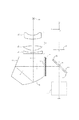
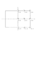
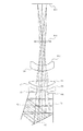
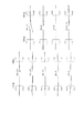
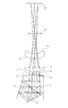
図1は本発明のファインダー光学系を備えたデジタル一眼レフカメラの要部断面図である。図2は本発明のファインダー光学系で観察される物体像の諸収差を焦点板上の位置座標を基準として説明するときの座標系の説明図である。図3と図4は本発明の数値実施例1のファインダー光学系の光路図と収差図である。図5と図6は本発明の数値実施例2のファインダー光学系の光路図と収差図である。図7と図8は本発明の数値実施例3のファインダー光学系の光路図と収差図である。 FIG. 1 is a cross-sectional view of a main part of a digital single-lens reflex camera equipped with a finder optical system of the present invention. FIG. 2 is an explanatory diagram of a coordinate system when various aberrations of an object image observed with the finder optical system of the present invention are described with reference to position coordinates on the focusing screen. 3 and 4 are an optical path diagram and an aberration diagram of the finder optical system according to Numerical Example 1 of the present invention. 5 and 6 are an optical path diagram and an aberration diagram of the finder optical system according to Numerical Example 2 of the present invention. 7 and 8 are an optical path diagram and an aberration diagram of the finder optical system according to Numerical Example 3 of the present invention.
これらの光路図と収差図は、標準視度である−1ディオプトリーである場合を示している。また、アイポイント8に焦点距離が約32mmの収差のない理想的なレンズを配置して結像させた状態を表しており、波長はd線としている。
These optical path diagrams and aberration diagrams show the case where the standard diopter is −1 diopter. In addition, an ideal lens without an aberration having a focal length of about 32 mm is arranged at the
収差図では、図2に示される焦点板4での各座標におけるY断面、X断面での横収差を表しており、縦軸の単位はmm、横軸はアイポイント8での光線高さを表している。
In the aberration diagram, the lateral aberration at the Y cross section and the X cross section at each coordinate on the focusing
図1において、1は不図示のカメラ本体に装着される撮影レンズである。2は回転軸2aを中心として回転可能なクイックリターンミラーであり、撮影時以外は撮影レンズ1からの光を上方に反射している。3は焦点板(フレネルレンズ)である。4は焦点板(マット面)であり、焦点板には撮影レンズ1によって物体像(ファインダー像)が形成されている。
In FIG. 1,
5は像反転手段としてのペンタダハミラーを構成する屋根型形状の第1ミラーであり、焦点板4に形成された物体像からの光を該物体像側へ反射している。6は第1ミラー5で物体側に反射された光を観察側(アイポイント側)に反射する第2ミラーである。本実施例における第2ミラー6は回転非対称面である。このように、第1ミラー5と第2ミラー6は像反転手段を構成しており、焦点板4に形成される物体像を正立正像としている。
7は接眼レンズであり、第2ミラー側からアイポイント側へ順に、負の屈折力を有する第1レンズ(負レンズ)7a、正の屈折力を有する第2レンズ(正レンズ)7b、そして負の屈折力を有する第3レンズ(負レンズ)7cを有している。第2ミラー6に最も近い第1レンズ7aの入射面は回転非対称面である。第2レンズ7bは両面が凸形状であって、両面とも回転対称面である。第3レンズ7cはアイポイント側が凹形状の回転対称面である。以上の構成によりアイレリーフを十分長くしている。
Reference numeral 7 denotes an eyepiece lens, which is, in order from the second mirror side to the eye point side, a first lens (negative lens) 7a having negative refractive power, a second lens (positive lens) 7b having positive refractive power, and negative A third lens (negative lens) 7c having a refractive power of 2. The incident surface of the first lens 7a closest to the
8はアイポイントを表している。9は撮影レンズ1の像面であり、CCDセンサやCMOSセンサ等の撮像素子またはフィルム等の撮像手段が配置される。
8 represents an eye point.
撮影レンズ1からの光はクイックリターンミラー2で反射されて、焦点板4に物体像(ファインダー像)が形成される。焦点板4に形成された物体像を第1ミラー5と第2ミラー6で正立像とし、該正立像を接眼レンズ7で拡大することによりアイポイント8で観察される。
Light from the
撮影時には撮像手段に像を形成するため、クイックリターンミラー2が2aを回転軸として回転し、撮影レンズ1からの光が像面9に入射する。像面9に配置された撮像手段によって焦点板4に形成された物体像に相当する像を受光している。
第2レンズ7bを接眼レンズ7の光軸に沿って移動させることで視度調節を行っている。
At the time of shooting, an image is formed on the image pickup means, so that the
Diopter adjustment is performed by moving the second lens 7 b along the optical axis of the eyepiece lens 7.
また、第2ミラー6を回転非対称面として、集光性のパワーを持たせることにより、ファインダー倍率を大きくしている。
Further, the finder magnification is increased by using the
また、第2ミラー6への入射光は斜入射光であるため偏心収差が発生するが、第2ミラー6を回転非対称面とすることで偏心収差の発生を低減している。
Further, since the incident light to the
接眼レンズが回転非対称面を少なくとも1面有することにより偏心収差をさらに良好に補正することができる。本実施例では、第1レンズ7aの入射面もしくは第1レンズ7aの入射出面両面を回転非対称面とし、第2ミラー6における残存偏心収差を良好に補正し、且つ該第1レンズ7aを射出した後の光を共軸系に戻している。これにより、第2レンズ7bを接眼レンズ7の光軸に沿って移動させる場合にも高い光学性能を維持したまま視度調節行うことができる。
Since the eyepiece has at least one rotationally asymmetric surface, decentration aberrations can be corrected more satisfactorily. In this embodiment, both the incident surface of the first lens 7a or the incident / exit surface of the first lens 7a are rotationally asymmetric surfaces, the residual decentration aberration in the
以下に本発明の実施例を図面に基づいて説明する。 Embodiments of the present invention will be described below with reference to the drawings.
本発明のファインダー光学系は、光学系の全系にわたる共通の光軸を持たない。そこで、本実施例においては撮影レンズ1の光軸が、クイックリターンミラー2により折り曲げられた軸と焦点板4(マット面)との交点を原点(図1の点O)とする絶対座標系を設定するとともに、絶対座標系の各軸を以下のように定める。
Y軸:原点を通り、第2レンズ7bの面頂点を結ぶ直線に平行で、該第2レンズ7bから第3レンズ7cに向かう方向をプラス方向とする。
Z軸:原点を通り、Y軸に対して紙面内で時計回りに90°をなす直線。
X軸:原点を通り、Z、Y各軸に垂直な直線(図1の紙面に垂直な直線)。
The viewfinder optical system of the present invention does not have a common optical axis over the entire optical system. Therefore, in this embodiment, an absolute coordinate system in which the optical axis of the photographing
Y axis: The direction from the second lens 7b toward the third lens 7c, passing through the origin and parallel to the straight line connecting the surface vertices of the second lens 7b, is defined as the plus direction.
Z axis: A straight line that passes through the origin and forms 90 ° clockwise with respect to the Y axis.
X axis: A straight line passing through the origin and perpendicular to each of the Z and Y axes (a straight line perpendicular to the paper surface of FIG. 1)
ファインダー光学系を構成する第i番目の面形状を表すには、第i面のローカル座標系を設定して、該ローカル座標系でその面の形状を表記する。 In order to represent the i-th surface shape constituting the finder optical system, a local coordinate system of the i-th surface is set, and the shape of the surface is described in the local coordinate system.
図3および図5では第i番目の面をRiで表している。また、第i面のYZ面内でのチルト角は絶対座標系のZ軸に対して反時計回り方向を正とした角度θi(単位°)で表す。各面のローカル座標の原点はYZ平面状にあり、XZ及びXY面内での面のチルト、シフトはない。 3 and 5, the i-th surface is represented by Ri. Further, the tilt angle of the i-th surface in the YZ plane is represented by an angle θi (unit: °) with the counterclockwise direction being positive with respect to the Z axis of the absolute coordinate system. The origin of the local coordinates of each surface is in the YZ plane, and there is no tilt or shift of the surface in the XZ and XY planes.
さらに第i面のローカル座標(x、y、z)のy軸、z軸は絶対座標系(X、Y、Z)に対してYZ平面内で角度θi傾いており、具体的には以下のように設定する。
z軸:ローカル座標の原点を通り、絶対座標系のZ方向に対しYZ面内において反時計回り方向に角度θiをなす直線。
y軸:ローカル座標の原点を通り、z方向に対しYZ面内において反時計回りに90°をなす直線。
x軸:ローカル座標の原点を通り、YZ面に対し垂直な直線。
Further, the y-axis and z-axis of the local coordinates (x, y, z) of the i-th surface are inclined by the angle θi in the YZ plane with respect to the absolute coordinate system (X, Y, Z). Set as follows.
z-axis: a straight line that passes through the origin of the local coordinates and forms an angle θi in the counterclockwise direction in the YZ plane with respect to the Z direction of the absolute coordinate system
y-axis: A straight line that passes through the origin of the local coordinates and forms 90 ° counterclockwise in the YZ plane with respect to the z direction.
x axis: A straight line passing through the origin of the local coordinates and perpendicular to the YZ plane.
またNdi、νdiはそれぞれ第i面と第(i+1)面間の媒質の屈折率とアッベ数である。尚、絞りやアイポイントも1つの平面として表示している。 Ndi and νdi are the refractive index and Abbe number of the medium between the i-th surface and the (i + 1) -th surface, respectively. The aperture and eye point are also displayed as one plane.
ファインダー光学系は、球面、回転対称な非球面、回転非対称な非球面を有する。球面は球面形状としてその曲率半径Riを記している。曲率半径の符号は、前記Y軸に沿って曲率中心がY軸のプラス側にある場合をプラス、Y軸のマイナス側にある場合をマイナスとする。
球面の形状は以下の式で表される。
z={(x2+y2)/Ri}/〔1+{1−(x2+y2)/Ri2}1/2〕
回転対称な非球面の形状は以下の式で表される。
z={(x2+y2)/Ri}/〔1+{1−(1+k)・(x2+y2)/Ri2}1/2〕+ka(x2+y2)2+kb(x2+y2)3+kc(x2+y2)6+・・・
回転非対称な非球面の形状は以下の式により表される。
A=(a+b)・(y2・cos2t+x2)
B=2a・b・cos t[1+{(b−a)・y・sin t/(2a・b)}+〔1+{(b−a)・y・sin t/(a・b)}−{y2/(a・b)}−{4a・b・cos2t+(a+b)2sin2t}x2/(4a2b2cos2t)〕1/2]
z=A/B+C02y2+C11xy+C20x2+C03y3+C12xy2+C21x2y+C30x3+C04y4+C13xy3+C22x2y2+C31x3y+C40x4・・・
なお、本発明の数値実施例の回転非対称面の形状は、上記の式において、
a=b=Ri,t=0
とする球面ベース非球面であり、xに関する偶数次の項のみを使用して奇数次の項を0とすることにより、yz面を対称面とする面対称な形状である。さらに以下の条件が満たされる場合はxz面に対して対称な形状を表す。
C03=C21=0
さらにC02=C20 C04=C40=C22/2が満たされる場合は回転対称な形状を表す。以上の条件を満たさない場合は非回転対称な形状である。なお、数値実施例において「e−X」の表示は「×10−X」を意味する。
The viewfinder optical system has a spherical surface, a rotationally symmetric aspheric surface, and a rotationally asymmetric aspheric surface. The spherical surface has a radius of curvature Ri as a spherical shape. The sign of the radius of curvature is positive when the center of curvature is on the positive side of the Y axis along the Y axis, and negative when the center of curvature is on the negative side of the Y axis.
The spherical shape is expressed by the following equation.
z = {(x2 + y2) / Ri} / [1+ {1- (x2 + y2) / Ri2} 1/2]
The shape of the rotationally symmetric aspheric surface is expressed by the following equation.
z = {(x2 + y2) / Ri} / [1+ {1- (1 + k). (x2 + y2) / Ri2} 1/2] + ka (x2 + y2) 2 + kb (x2 + y2) 3 + kc (x2 + y2) 6+.
The shape of the rotationally asymmetric aspheric surface is expressed by the following equation.
A = (a + b) · (y2 · cos2t + x2)
B = 2a * b * cost [1 + {(ba) * y * sin t / (2a * b)} + [1 + {(ba) * y * sint / (a * b)}- {Y2 / (a · b)} − {4a · b · cos2t + (a + b) 2sin2t} x2 / (4a2b2cos2t)] 1/2]
z = A / B + C02y2 + C11xy + C20x2 + C03y3 + C12xy2 + C21x2y + C30x3 + C04y4 + C13xy3 + C22x2y2 + C31x3y + C40x4 ...
In addition, the shape of the rotationally asymmetric surface of the numerical example of the present invention is the above formula,
a = b = Ri, t = 0
A spherical base aspherical surface, and by using only even-order terms relating to x and setting odd-order terms to 0, the surface is symmetrical with the yz plane as the symmetry plane. Furthermore, when the following conditions are satisfied, it represents a symmetrical shape with respect to the xz plane.
C03 = C21 = 0
Furthermore, when C02 = C20 C04 = C40 = C22 / 2 is satisfied, it represents a rotationally symmetric shape. When the above conditions are not satisfied, the shape is non-rotationally symmetric. In the numerical examples, “e−X” represents “× 10 −X ”.

本発明の好ましい実施例について説明したが、本発明はこれらの実施例に限定されないことはいうまでもなく、その要旨の範囲内で種々の変形及び変更が可能である。 Although the preferred embodiments of the present invention have been described, it goes without saying that the present invention is not limited to these embodiments, and various modifications and changes can be made within the scope of the gist thereof.
本発明によれば、高い光学性能を保ちつつ観察倍率が大きく、大きなファインダー像の観察ができ、アイレリーフを十分に長く確保することのできるファインダー光学系及びそれを用いた撮像装置を得ることができる。 According to the present invention, it is possible to obtain a finder optical system capable of observing a large finder image while maintaining high optical performance, observing a large finder image, and ensuring an eye relief sufficiently long, and an imaging apparatus using the finder optical system. it can.
1 撮影レンズ
2 クイックリターンミラー
3 焦点板(フレネルレンズ)
4 焦点板(マット面)
5 第1ミラー(屋根型形状のミラー)
6 第2ミラー
7 接眼レンズ
7a 第1レンズ
7b 第2レンズ
7c 第3レンズ
8 アイポイント
9 像面
1
4 Focus plate (matte surface)
5 First mirror (roof-shaped mirror)
6 second mirror 7 eyepiece 7a first lens 7b second lens 7c
Claims (2)
Priority Applications (2)
| Application Number | Priority Date | Filing Date | Title |
|---|---|---|---|
| JP2007051575A JP5043473B2 (en) | 2006-06-08 | 2007-03-01 | Viewfinder optical system and imaging apparatus using the same |
| US11/745,075 US7630627B2 (en) | 2006-06-08 | 2007-05-07 | Viewfinder optical system and image pickup apparatus including the same |
Applications Claiming Priority (3)
| Application Number | Priority Date | Filing Date | Title |
|---|---|---|---|
| JP2006159657 | 2006-06-08 | ||
| JP2006159657 | 2006-06-08 | ||
| JP2007051575A JP5043473B2 (en) | 2006-06-08 | 2007-03-01 | Viewfinder optical system and imaging apparatus using the same |
Publications (3)
| Publication Number | Publication Date |
|---|---|
| JP2008015475A JP2008015475A (en) | 2008-01-24 |
| JP2008015475A5 JP2008015475A5 (en) | 2010-04-02 |
| JP5043473B2 true JP5043473B2 (en) | 2012-10-10 |
Family
ID=38822102
Family Applications (1)
| Application Number | Title | Priority Date | Filing Date |
|---|---|---|---|
| JP2007051575A Expired - Fee Related JP5043473B2 (en) | 2006-06-08 | 2007-03-01 | Viewfinder optical system and imaging apparatus using the same |
Country Status (2)
| Country | Link |
|---|---|
| US (1) | US7630627B2 (en) |
| JP (1) | JP5043473B2 (en) |
Families Citing this family (7)
| Publication number | Priority date | Publication date | Assignee | Title |
|---|---|---|---|---|
| FR2864400B1 (en) * | 2003-12-23 | 2006-03-31 | Cit Alcatel | ELECTRONIC DEVICE COMPRISING AN ORIENTABLE CAMERA |
| US7761003B2 (en) * | 2007-05-24 | 2010-07-20 | Nikon Corporation | Optical apparatus and manufacturing method of optical apparatus |
| TWI446084B (en) * | 2012-02-07 | 2014-07-21 | Ability Entpr Co Ltd | Electronic view finder |
| JP2013214007A (en) * | 2012-04-04 | 2013-10-17 | Canon Inc | Finder optical system and imaging device |
| JP6318543B2 (en) * | 2013-10-25 | 2018-05-09 | リコーイメージング株式会社 | Viewfinder optical system |
| DE102016106953A1 (en) | 2016-04-14 | 2017-10-19 | Arnold & Richter Cine Technik Gmbh & Co. Betriebs Kg | camera viewfinder |
| KR102544194B1 (en) * | 2020-11-02 | 2023-06-15 | 삼성전기주식회사 | Optical Imaging System |
Family Cites Families (6)
| Publication number | Priority date | Publication date | Assignee | Title |
|---|---|---|---|---|
| JPH03287109A (en) * | 1990-04-02 | 1991-12-17 | Minolta Camera Co Ltd | Finder optical system |
| JP2000356799A (en) | 1999-06-14 | 2000-12-26 | Canon Inc | Finder |
| JP3766257B2 (en) | 2000-05-01 | 2006-04-12 | 株式会社シグマ | Viewfinder optical system |
| US7068258B2 (en) * | 2000-05-12 | 2006-06-27 | Emagin Corporation | Portable communication device with virtual image display module |
| JP4800518B2 (en) * | 2001-08-03 | 2011-10-26 | オリンパス株式会社 | Decentered optical system and projection display device using the same |
| JP2003107355A (en) * | 2001-09-27 | 2003-04-09 | Olympus Optical Co Ltd | Imaging optical system |
-
2007
- 2007-03-01 JP JP2007051575A patent/JP5043473B2/en not_active Expired - Fee Related
- 2007-05-07 US US11/745,075 patent/US7630627B2/en not_active Expired - Fee Related
Also Published As
| Publication number | Publication date |
|---|---|
| JP2008015475A (en) | 2008-01-24 |
| US7630627B2 (en) | 2009-12-08 |
| US20070286594A1 (en) | 2007-12-13 |
Similar Documents
| Publication | Publication Date | Title |
|---|---|---|
| JP5043473B2 (en) | Viewfinder optical system and imaging apparatus using the same | |
| JP2009109723A (en) | Optical system and imaging device provided with it | |
| JPH10221604A (en) | Optical system and image pickup unit using the same | |
| JP5344534B2 (en) | Viewfinder optical system and imaging apparatus using the same | |
| JPH07225411A (en) | Lighting type bright frame finder | |
| JP2009251323A (en) | Observation optical system and imaging device with the same | |
| JP4914121B2 (en) | Eyepiece optical system and viewfinder optical system having the same | |
| JP4097932B2 (en) | Single-lens reflex camera with eyepiece | |
| JP4792896B2 (en) | Reduction optical system and optical apparatus equipped with the same | |
| JP2008052085A (en) | Eyepiece lens and finder optical system having the same and optical apparatus | |
| JP5611095B2 (en) | Viewfinder optical system and imaging apparatus having the same | |
| US6351338B2 (en) | Image pickup optical system | |
| JP2009080410A (en) | Optical system and endoscope using the same | |
| JPH11202205A (en) | Optical element and optical system using the same | |
| JP2008129059A (en) | Finder optical system and imaging device using same | |
| JP4212295B2 (en) | Single-lens reflex camera with eyepiece | |
| JP2008241795A (en) | Finder optical system and imaging apparatus using same | |
| JP2520683B2 (en) | Single-lens reflex camera viewfinder | |
| JP4908976B2 (en) | Viewfinder optical system and imaging apparatus using the same | |
| JP5506576B2 (en) | Viewfinder optical system and imaging apparatus having the same | |
| JP7532094B2 (en) | Observation device and imaging device | |
| JP2007322967A (en) | Finder optical system and optical apparatus equipped with the same | |
| JPH09222564A (en) | Erect optical system | |
| JPH10312004A (en) | Finder optical system for single lens reflex camera | |
| JP2003057723A (en) | Finder optical system and camera |
Legal Events
| Date | Code | Title | Description |
|---|---|---|---|
| RD04 | Notification of resignation of power of attorney |
Free format text: JAPANESE INTERMEDIATE CODE: A7424 Effective date: 20100201 |
|
| A521 | Request for written amendment filed |
Free format text: JAPANESE INTERMEDIATE CODE: A523 Effective date: 20100212 |
|
| A621 | Written request for application examination |
Free format text: JAPANESE INTERMEDIATE CODE: A621 Effective date: 20100212 |
|
| RD01 | Notification of change of attorney |
Free format text: JAPANESE INTERMEDIATE CODE: A7421 Effective date: 20100630 |
|
| A977 | Report on retrieval |
Free format text: JAPANESE INTERMEDIATE CODE: A971007 Effective date: 20120119 |
|
| A131 | Notification of reasons for refusal |
Free format text: JAPANESE INTERMEDIATE CODE: A131 Effective date: 20120417 |
|
| A521 | Request for written amendment filed |
Free format text: JAPANESE INTERMEDIATE CODE: A523 Effective date: 20120618 |
|
| TRDD | Decision of grant or rejection written | ||
| A01 | Written decision to grant a patent or to grant a registration (utility model) |
Free format text: JAPANESE INTERMEDIATE CODE: A01 Effective date: 20120710 |
|
| A01 | Written decision to grant a patent or to grant a registration (utility model) |
Free format text: JAPANESE INTERMEDIATE CODE: A01 |
|
| A61 | First payment of annual fees (during grant procedure) |
Free format text: JAPANESE INTERMEDIATE CODE: A61 Effective date: 20120712 |
|
| FPAY | Renewal fee payment (event date is renewal date of database) |
Free format text: PAYMENT UNTIL: 20150720 Year of fee payment: 3 |
|
| LAPS | Cancellation because of no payment of annual fees |