JP5041002B2 - Communications system - Google Patents
Communications system Download PDFInfo
- Publication number
- JP5041002B2 JP5041002B2 JP2009535780A JP2009535780A JP5041002B2 JP 5041002 B2 JP5041002 B2 JP 5041002B2 JP 2009535780 A JP2009535780 A JP 2009535780A JP 2009535780 A JP2009535780 A JP 2009535780A JP 5041002 B2 JP5041002 B2 JP 5041002B2
- Authority
- JP
- Japan
- Prior art keywords
- node
- intermediate device
- link
- downlink
- uplink
- Prior art date
- Legal status (The legal status is an assumption and is not a legal conclusion. Google has not performed a legal analysis and makes no representation as to the accuracy of the status listed.)
- Expired - Fee Related
Links
Images


Classifications
-
- H—ELECTRICITY
- H04—ELECTRIC COMMUNICATION TECHNIQUE
- H04B—TRANSMISSION
- H04B17/00—Monitoring; Testing
- H04B17/30—Monitoring; Testing of propagation channels
- H04B17/309—Measuring or estimating channel quality parameters
-
- H—ELECTRICITY
- H04—ELECTRIC COMMUNICATION TECHNIQUE
- H04W—WIRELESS COMMUNICATION NETWORKS
- H04W52/00—Power management, e.g. TPC [Transmission Power Control], power saving or power classes
- H04W52/04—TPC
- H04W52/38—TPC being performed in particular situations
- H04W52/46—TPC being performed in particular situations in multi hop networks, e.g. wireless relay networks
-
- H—ELECTRICITY
- H04—ELECTRIC COMMUNICATION TECHNIQUE
- H04B—TRANSMISSION
- H04B7/00—Radio transmission systems, i.e. using radiation field
- H04B7/14—Relay systems
- H04B7/15—Active relay systems
-
- H—ELECTRICITY
- H04—ELECTRIC COMMUNICATION TECHNIQUE
- H04L—TRANSMISSION OF DIGITAL INFORMATION, e.g. TELEGRAPHIC COMMUNICATION
- H04L1/00—Arrangements for detecting or preventing errors in the information received
- H04L1/0001—Systems modifying transmission characteristics according to link quality, e.g. power backoff
- H04L1/0023—Systems modifying transmission characteristics according to link quality, e.g. power backoff characterised by the signalling
- H04L1/0028—Formatting
- H04L1/0029—Reduction of the amount of signalling, e.g. retention of useful signalling or differential signalling
-
- H—ELECTRICITY
- H04—ELECTRIC COMMUNICATION TECHNIQUE
- H04L—TRANSMISSION OF DIGITAL INFORMATION, e.g. TELEGRAPHIC COMMUNICATION
- H04L1/00—Arrangements for detecting or preventing errors in the information received
- H04L1/0001—Systems modifying transmission characteristics according to link quality, e.g. power backoff
- H04L1/0002—Systems modifying transmission characteristics according to link quality, e.g. power backoff by adapting the transmission rate
- H04L1/0003—Systems modifying transmission characteristics according to link quality, e.g. power backoff by adapting the transmission rate by switching between different modulation schemes
-
- H—ELECTRICITY
- H04—ELECTRIC COMMUNICATION TECHNIQUE
- H04L—TRANSMISSION OF DIGITAL INFORMATION, e.g. TELEGRAPHIC COMMUNICATION
- H04L1/00—Arrangements for detecting or preventing errors in the information received
- H04L1/0001—Systems modifying transmission characteristics according to link quality, e.g. power backoff
- H04L1/0009—Systems modifying transmission characteristics according to link quality, e.g. power backoff by adapting the channel coding
-
- H—ELECTRICITY
- H04—ELECTRIC COMMUNICATION TECHNIQUE
- H04L—TRANSMISSION OF DIGITAL INFORMATION, e.g. TELEGRAPHIC COMMUNICATION
- H04L1/00—Arrangements for detecting or preventing errors in the information received
- H04L2001/0092—Error control systems characterised by the topology of the transmission link
- H04L2001/0097—Relays
Description
本発明は通信システムに関する。 The present invention relates to a communication system.
カバレッジ範囲の拡大とシステム容量(スループット)の増大の両方が可能であるとして、パケットベースの無線(radio)システム等においてマルチホップ方式の利用が現在注目を集めている。 The use of a multi-hop scheme is currently attracting attention in packet-based radio systems and the like, as both the coverage range and system capacity (throughput) can be increased.
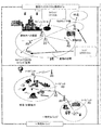
マルチホップ通信システムでは、送信元装置から1つまたはそれ以上の中間装置を介して送信先装置に至る通信経路(C)に沿って一通信方向に通信信号を送信する。図3は、単一セル、ツー(2)ホップ・ワイヤレス通信システムを示す。このシステムは、基地局BS(第3世代通信システムでは「ノードB(NB)」として知られている)と、中継ノードRN(中継局RSとしても知られている)と、ユーザ装置UE(移動局MSとしても知られている)とを含む。信号をダウンリンク(DL)で基地局から中継ノード(RN)を介して送信先のユーザ装置(UE)に送信する場合、基地局が送信元局(S)であり、ユーザ装置が送信先局(D)である。信号をアップリンク(UL)でユーザ装置(UE)から中継ノード(RN)を介して基地局に送信する場合、ユーザ装置が送信元局であり、基地局が送信先局である。中継ノードは中間装置(I)の一例であり、送信元装置からデータを受信するレシーバと、そのデータまたはそれから派生したデータを送信先装置に送信するトランスミッタとを有する。 In a multi-hop communication system, a communication signal is transmitted in one communication direction along a communication path (C) from a transmission source device to a transmission destination device via one or more intermediate devices. FIG. 3 shows a single cell, two (2) hop wireless communication system. This system comprises a base station BS (also known as “Node B (NB)” in the third generation communication system), a relay node RN (also known as a relay station RS), and a user equipment UE (mobile Also known as station MS). When a signal is transmitted from the base station via the relay node (RN) via the downlink (DL) to the transmission destination user apparatus (UE), the base station is the transmission source station (S), and the user apparatus is the transmission destination station. (D). When a signal is transmitted from the user apparatus (UE) to the base station via the relay node (RN) via the uplink (UL), the user apparatus is a transmission source station and the base station is a transmission destination station. The relay node is an example of the intermediate device (I), and includes a receiver that receives data from the transmission source device and a transmitter that transmits the data or data derived therefrom to the transmission destination device.
従来、デッドスポット(dead spots)のカバレッジのために、単純なアナログリピータやデジタルリピータを中継局として利用していた。これらのリピータは、送信元局とは異なる送信周波数で動作して送信元からの送信とリピータからの送信とが干渉しないようにするか、送信元局が送信していない時に動作する。 Conventionally, a simple analog repeater or a digital repeater has been used as a relay station for coverage of dead spots. These repeaters operate at a transmission frequency different from that of the transmission source station so that transmission from the transmission source and transmission from the repeater do not interfere with each other, or operate when the transmission source station is not transmitting.
図4は、中継局のアプリケーションを示す図である。固定インフラストラクチャの場合、中継局が提供するカバレッジは、移動局が物の影に入り、または基地局のカバレッジ範囲内にいるが基地局から十分な信号強度を得られないときに、通信ネットワークにアクセスさせる「インフィル(in-fill)」であってもよい。移動局が基地局の通常のデータ送信範囲外にいるときにアクセスさせる「範囲拡大」も示されている。図4の右上に示したインフィルの例は、地上レベルまたはその上下におけるビル内のカバレッジを可能とするノーマディック中継局の配置である。 FIG. 4 is a diagram illustrating an application of the relay station. In the case of a fixed infrastructure, the coverage provided by the relay station is the same as the communication network when the mobile station is in the shadow of an object or is within the coverage area of the base station but cannot obtain sufficient signal strength from the base station. It may be an “in-fill” to access. Also shown is “range extension” which allows the mobile station to access when outside the normal data transmission range of the base station. The example of the infill shown in the upper right of FIG. 4 is an arrangement of nomadic relay stations that enables coverage in the building at the ground level or above and below it.
その他のアプリケーションは、イベントや緊急時・災害時にアクセスを提供する一時的カバー(temporary cover)を発揮するノーマディック中継局である。図4の右下に示したアプリケーションは、車両に載せた中継局を用いてネットワークへのアクセスを提供する。 Other applications are nomadic relay stations that provide a temporary cover to provide access in the event or emergency / disaster. The application shown in the lower right of FIG. 4 provides access to the network using a relay station mounted on the vehicle.
下に説明するように、中継を、通信システムのゲインを向上する高度な送信技術とともに利用してもよい。 As described below, relays may be utilized with advanced transmission techniques that improve the gain of the communication system.
無線通信の散乱や吸収により伝搬損失、すなわち「経路損失」が生じるので、信号強度は小さくなる。トランスミッタとレシーバとの間の経路損失に影響する要因には次のものがある:トランスミッタのアンテナ高さ、レシーバのアンテナの高さ、キャリア周波数、混雑具合(clutter type)(都会、半都会、郊外)、高度等の詳細な形態、密度、セパレーション(separation)、地形(起伏がある、平地)。トランスミッタとレシーバの間の経路損失L(dB)を次式でモデル化できる:

ここで、d(メートル)はトランスミッタとレシーバのセパレーション(separation)であり、b(db)とnは経路損失パラメータであり、経路損失の絶対値はl=10(L/10)で与えられる。
Propagation loss, that is, “path loss” occurs due to scattering and absorption of wireless communication, so that the signal strength is reduced. Factors that affect the path loss between the transmitter and receiver include: transmitter antenna height, receiver antenna height, carrier frequency, clutter type (urban, semi-urban, suburban) ), Detailed form such as altitude, density, separation, topography (with ups and downs, flat ground). The path loss L (dB) between the transmitter and receiver can be modeled by:
Here, d (meter) is the separation between the transmitter and the receiver, b (db) and n are path loss parameters, and the absolute value of the path loss is given by l = 10 (L / 10).
間接リンクSI+IDで生じる絶対経路損失は、直接リンクSDで生じる経路損失より小さいこともあり得る。換言すると、次式が成り立つこともある:
1つの送信リンクを2つの短い送信セグメントに分割すれば、経路損失と距離との間の非線形関係を利用できる。式(A)を用いた経路損失の簡単な理論的分析から、送信元装置から中間装置(例えば中継ノード)を介して送信先装置に信号を送信すると、送信元装置から送信先装置に直接送信するよりも全体的な経路損失は少なくでき、信号強度およびそれによるデータスループットの改善ができることが分かる。適切に実施すれば、マルチホップ通信システムにより、ワイヤレス送信を行うトランスミッタの送信パワーを低減することができ、干渉レベルが低くなり、電磁放射にさらされる量が減る。あるいは、全体的な経路損失が減ることにより、信号伝達に必要な放射送信パワーを増やさなくても、レシーバにおける受信信号品質が良くなる。 Dividing one transmission link into two short transmission segments can take advantage of the nonlinear relationship between path loss and distance. From a simple theoretical analysis of path loss using equation (A), when a signal is transmitted from a transmission source device to a transmission destination device via an intermediate device (for example, a relay node), it is directly transmitted from the transmission source device to the transmission destination device. It can be seen that the overall path loss can be less than that, and that signal strength and thereby data throughput can be improved. When implemented properly, a multi-hop communication system can reduce the transmit power of a transmitter that performs wireless transmission, lowering the level of interference and reducing the amount of exposure to electromagnetic radiation. Alternatively, since the overall path loss is reduced, the received signal quality at the receiver is improved without increasing the radiated transmission power required for signal transmission.
マルチホップシステムはマルチキャリア送信での利用に適している。FDM(周波数分割多重)、OFDM(直交周波数分割多重)、またはDMT(離散マルチトーン)などのマルチキャリア送信システムでは、1つのデータストリームをN個の並列のサブキャリアに変調する。各サブキャリア信号はそれ自体の周波数範囲を有する。こうすることにより、帯域幅全体を複数のサブキャリアに分割し、各データシンボルの長さを長くすることができる。各サブキャリアの情報レートは低いので、マルチキャリアシステムはシングルキャリアシステムと比較して、チャネルに生じる歪み(channel induced distortion)に対する抵抗力が強いという点で利益がある。これは、各サブキャリアの送信レートと帯域幅とがそのチャネルのコヒーレンス帯域幅(coherence bandwidth)より小さくすることにより可能となる。結果として、信号サブキャリアに生じるチャネル歪みは周波数に依存するので、簡単な位相及び振幅の補正ファクタにより補正することができる。このように、システム帯域幅がチャネルのコヒーレンス帯域幅より大きいとき、マルチキャリアレシーバ内のチャネル歪み補正部(channel distortion correction entity)は、シングルキャリアレシーバ内の対応するチャネル歪み補正部より、非常に簡単なものとすることができる。 Multihop systems are suitable for use in multicarrier transmission. In a multicarrier transmission system such as FDM (Frequency Division Multiplexing), OFDM (Orthogonal Frequency Division Multiplexing), or DMT (Discrete Multitone), one data stream is modulated into N parallel subcarriers. Each subcarrier signal has its own frequency range. In this way, the entire bandwidth can be divided into a plurality of subcarriers, and the length of each data symbol can be increased. Since the information rate of each subcarrier is low, a multicarrier system is advantageous in that it is more resistant to channel induced distortion than a single carrier system. This is possible by making the transmission rate and bandwidth of each subcarrier smaller than the coherence bandwidth of the channel. As a result, the channel distortion generated in the signal subcarrier depends on the frequency, and can be corrected by a simple phase and amplitude correction factor. Thus, when the system bandwidth is greater than the channel coherence bandwidth, the channel distortion correction entity in a multicarrier receiver is much simpler than the corresponding channel distortion correction unit in a single carrier receiver. Can be.
直交周波数分割多重(OFDM)はFDMに基づく変調方式である。OFDMシステムは、サブキャリアのスペクトルが相互に独立であるために干渉を起こさずにオーバーラップできるように、数学的に直交する複数のサブキャリア周波数を利用する。OFDMシステムの直交性により、ガードバンド周波数が必要なくなり、そのためにシステムのスペクトル的効率性が高くなる。OFDMは多くのワイヤレスシステムに提案され、受け入れられている。OFDMは、非対称デジタル加入者線(ADSL)接続、一部のワイヤレスLANアプリケーション(例えば、IEEE802.11a/g標準に基づくWiFiデバイス)、(IEEE802.16標準に基づく)WiMAX等の一部のワイヤレスMANアプリケーションで現在使用されている。OFDMは、エラー訂正方法であるチャネルコーディングとともにしばしば用いられ、コード化直交FDMすなわちCOFDMとなる。COFDMは今日デジタル電気通信システムで広く用いられ、周波数領域のサブキャリアと時間領域のシンボルの両方にわたりチャネル歪みの変化があるマルチパス環境において、OFDMベースシステムの性能を向上させている。本システムはビデオやオーディオのブロードキャスト(例えばDVBやDAB)やある種のコンピュータネットワーク技術で使用できる。 Orthogonal frequency division multiplexing (OFDM) is a modulation scheme based on FDM. An OFDM system utilizes a plurality of mathematically orthogonal subcarrier frequencies so that the subcarrier spectra are independent of each other so that they can overlap without causing interference. The orthogonality of the OFDM system eliminates the need for guard band frequencies, which increases the spectral efficiency of the system. OFDM has been proposed and accepted by many wireless systems. OFDM is an asymmetric digital subscriber line (ADSL) connection, some wireless LAN applications (eg, WiFi devices based on the IEEE 802.11a / g standard), some wireless MANs such as WiMAX (based on the IEEE 802.16 standard), etc. Currently used in the application. OFDM is often used with channel coding, which is an error correction method, resulting in coded orthogonal FDM or COFDM. COFDM is now widely used in digital telecommunications systems to improve the performance of OFDM-based systems in multipath environments where there is a change in channel distortion across both frequency domain subcarriers and time domain symbols. The system can be used with video and audio broadcasts (eg DVB and DAB) and certain computer network technologies.
OFDMシステムでは、トランスミッタにおいて、N個の変調パラレルデータソース信号のブロックを逆離散フーリエ変換(IDFT)アルゴリズムまたは逆高速フーリエ変換(IFFT)を用いることにより、N個の直交パラレルサブキャリアにマッピングし、時間領域の「OFDMシンボル」として知られる信号を形成する。このように、「OFDMシンボル」はN個のサブキャリア信号すべてを合成した信号である。OFDMシンボルは数学的には次式で表せる:
ここで、ΔfはHz単位のサブキャリアのセパレーションであり、Ts=1/Δfは秒単位のシンボル時間であり、cnは変調ソース信号である。各ソース信号で変調される式(1)のサブキャリアベクトルはc∈Cnであり、c=(c0,c1..cN−1)は有限のコンステレーションのうちのN個のコンステレーションシンボルのベクトルである。レシーバにおいて、受信した時間領域信号を、離散フーリエ変換(DFT)アルゴリズムまたは高速フーリエ変換(FFT)アルゴリズムを適用して周波数領域に変換して戻す。
In an OFDM system, at a transmitter, a block of N modulated parallel data source signals is mapped to N orthogonal parallel subcarriers using an inverse discrete Fourier transform (IDFT) algorithm or an inverse fast Fourier transform (IFFT), Forms a signal known as an “OFDM symbol” in the time domain. Thus, an “OFDM symbol” is a signal obtained by combining all N subcarrier signals. An OFDM symbol can be expressed mathematically as:
Where Δf is the subcarrier separation in Hz, Ts = 1 / Δf is the symbol time in seconds, and cn is the modulation source signal. The subcarrier vector of Equation (1) modulated by each source signal is cεCn, and c = (c0, c1... CN−1) is a vector of N constellation symbols in a finite constellation. It is. At the receiver, the received time domain signal is transformed back to the frequency domain by applying a discrete Fourier transform (DFT) algorithm or a fast Fourier transform (FFT) algorithm.
OFDMA(Orthogonal Frequency Division Multiple Access)はOFDMの多重アクセスのための変化形である。OFDMAは、個々のユーザにサブキャリアの一部を割り当てることにより動作する。これにより、複数のユーザから同時に送信ができ、スペクトル効率がよくなる。しかし、依然として、干渉を起こさずに双方向すなわちアップリンクとダウンリンクの両方向での通信を可能にする課題がある。 OFDMA (Orthogonal Frequency Division Multiple Access) is a variation for OFDM multiple access. OFDMA operates by assigning a portion of subcarriers to individual users. This allows simultaneous transmission from multiple users, improving spectral efficiency. However, there is still a problem that enables communication in both directions, that is, both uplink and downlink, without causing interference.
2つのノード間の双方向通信を可能にするため、2つの通信リンク(フォワードすなわちダウンロードと、リバースすなわちアップリンク)を二重化して、装置が同一リソース媒体上で同時に送受信できないという物理的な制約を克服する2つの周知のアプローチがある。第1のアプローチは、周波数分割多重(FDD)であり、伝送媒体をフォワードリンク通信用とリバースリンク通信用の2つの帯域にさらに分割して、2つのリンクを同時に、しかし相異なる周波数帯域で動作させるものである。第2のアプローチは、時分割多重(TDD)であり、どの時点でもフォワードリンクまたはリバースリンクのみが媒体を利用できるように、する2つのリンクを同一周波数帯域上で動作させるが、時間的により媒体へのアクセスをさらに分割するものである。どちらのアプローチ(TDD及びFDD)も他方と比較してそれ自体のメリットがあり、両方ともシングルホップの有線及び無線の通信システムでよく利用される方式である。例えば、IEEE802.16規格にはFDDモードとTDDモードが両方とも組み入れられている。 In order to enable two-way communication between two nodes, the two communication links (forward or download and reverse or uplink) are duplicated, so that the physical restriction that the device cannot transmit and receive simultaneously on the same resource medium. There are two well known approaches to overcome. The first approach is frequency division multiplexing (FDD), which further divides the transmission medium into two bands for forward link communication and reverse link communication, operating the two links simultaneously but in different frequency bands It is something to be made. The second approach is time division multiplexing (TDD), which allows two links to operate on the same frequency band so that only the forward link or reverse link can use the medium at any given time, Access is further divided. Both approaches (TDD and FDD) have their own merits compared to the other, both of which are often used in single-hop wired and wireless communication systems. For example, the IEEE 802.16 standard incorporates both an FDD mode and a TDD mode.
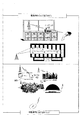
一例として、図5はIEEE802.16規格(WiMAX)のOFDMA物理レイヤモードで利用されるシングルホップTDDフレーム構成を示す図である。 As an example, FIG. 5 is a diagram illustrating a single-hop TDD frame configuration used in the OFDMA physical layer mode of the IEEE 802.16 standard (WiMAX).
各フレームはDLサブフレームとULサブフレームに分割され、各サブフレームは別々の送信インターバルである。フレームは送受信トランジションガードインターバル(TTG)と受送信トランジションガードインターバル(RTG)により分離されている。各DLサブフレームは、プリアンブルで始まり、フレーム制御ヘッダ(FCH)、DLマップ、ULマップが続く。 Each frame is divided into a DL subframe and a UL subframe, and each subframe is a separate transmission interval. The frames are separated by a transmission / reception transition guard interval (TTG) and a transmission / reception transition guard interval (RTG). Each DL subframe begins with a preamble, followed by a frame control header (FCH), a DL map, and a UL map.
フレーム制御ヘッダは、バーストプロファイルとDLマップの長さとを指定するDLフレームプレフィックス(DLFP)を含む。DLFPは各フレームの始めに送信されるデータ構成であり、カレントフレーム(current frame)に関する情報を含む。DLFPはFCHにマッピングされる。 The frame control header includes a DL frame prefix (DLFP) that specifies the burst profile and the length of the DL map. DLFP is a data structure transmitted at the beginning of each frame, and includes information on the current frame. DLFP is mapped to FCH.
同時ダウンリンクアロケーション(simultaneous DL allocations)をブロードキャスト、マルチキャスト、またはユニキャストしてもよいし、担当している(serving)BS以外のBSのアロケーションを含んでいてもよい。同時アップリンクはデータアロケーションであっても、レンジング(ranging)要求または帯域幅要求であってもよい。 Simultaneous downlink allocations (simultaneous DL allocations) may be broadcast, multicast, or unicast, or may include allocations of BSs other than the serving BS. The simultaneous uplink may be a data allocation, a ranging request or a bandwidth request.
具体的に、送信モデムのチャネル環境への高速適応(すなわち、変調・符号化、MIMO動作、平ループパワー制御の適応)を容易にするため、中継局が集中的に(すなわち非ローカル的に)制御されているとき、受信器は一般的に受信信号品質とその他のパラメータの測定情報(CQI)等のリンク品質の指標を提供する必要がある。そうすると送信機は現在の状況に適応できる。 Specifically, relay stations are concentrated (ie non-locally) to facilitate fast adaptation to the channel environment of the transmitting modem (ie modulation and coding, MIMO operation, adaptation of flat loop power control). When controlled, the receiver typically needs to provide an indication of link quality, such as received signal quality and other parameter measurement information (CQI). The transmitter can then adapt to the current situation.
しかし、問題は、例えばEP05257911.7に記載されているように、必要となるシグナリング帯域幅が、存在する余分なリンクのために非常に大きくなり、この情報がすべてBS(または、一般的な意味での制御装置(controlling entity))に送り返されなければならないことである。リンクパラメータの送信に関するEP05257911.7の内容はここに参照援用し、この出願のコピーをここに提出する。問題の理解を支援するために、簡単なツーホップの場合のシナリオにおける必要性(requirements)を図1に示す。 However, the problem is that the required signaling bandwidth becomes very large due to the extra links present, for example as described in EP05257911.7, and this information is all BS (or general meaning) Must be sent back to the controlling entity. The contents of EP05257911.7 concerning the transmission of link parameters are incorporated herein by reference and a copy of this application is filed here. To assist in understanding the problem, the requirements in a simple two-hop scenario are shown in FIG.
本発明は独立項に記載されており、ここで参照する。有利な実施形態は従属項に記載した。 The invention is described in the independent claims and is referred to here. Advantageous embodiments are described in the dependent claims.
添付した図面を参照して、単なる例示により、本発明の好ましい特徴をここに説明する。
フレームフォーマットの詳細については、代理人参照番号P107330GB00とP107297GB00を付した、本出願人による同日出願の2つの特許出願、及び以前の特許出願GB0616477.6、GB0616481.8、及びGB0616479.2を参照されたい。これらの各出願は本出願人が提案する相互に関連する発明を記載している。これらの各出願の内容はここに参照援用し、そのコピーをともに提出する。 For details of the frame format, reference is made to two patent applications of the same applicant dated at the same time, assigned with reference numbers P107330GB00 and P107297GB00, and earlier patent applications GB06164777.6, GB0616481.8, and GB06167.29.2. I want. Each of these applications describes an interrelated invention proposed by the applicant. The contents of each of these applications are incorporated herein by reference and a copy is submitted together.
シングルホップネットワークで必要なのは、受信器においてはダウンリンクのCQIの基地局への報告だけだが、中継局においては、その中継局に接続された各移動局のCQI値のペアだけでなく、ダウンリンクのCQIの報告を必要とする。802.16標準の内容はここに参照援用するが、この802.16標準では、QPSK変調を用いて4ビットまたは6ビットのCQI値を1スロット(すなわち、48サブキャリア)(これは3ビット値の場合には半スロット=24サブキャリアであることに注意)に別々にマッピングするので、シングルホップの場合よりも一般的にはロバスト(robust)であろうリンクを通してかかる大量の情報を搬送するメカニズムは非効率的である。本発明の実施形態により、アクセスリンクのCQIペアを1つのチャネルにパック(pack)することにより、ツーホップの場合に必要なシグナリングオーバーヘッドをシングルホップの場合に必要なのと同じレベルまで低減する、非常に簡単なシグナリングの解決策を提供する。 In a single-hop network, the receiver only needs to report the downlink CQI to the base station, but in the relay station, not only the pair of CQI values of each mobile station connected to the relay station but also the downlink Requires CQI reporting. The contents of the 802.16 standard are hereby incorporated by reference, and in this 802.16 standard, QPSK modulation is used to convert a 4-bit or 6-bit CQI value into one slot (ie, 48 subcarriers) (this is a 3-bit value). In this case, the half slot = 24 subcarriers), which are mapped separately), so a mechanism to carry such a large amount of information over a link that would be generally more robust than the single hop case Is inefficient. Embodiments of the present invention reduce the signaling overhead required for the two-hop case to the same level as required for the single hop by packing the CQI pair of the access link into one channel, Provide a simple signaling solution.
図2は、コネクションIDをCQIチャネル(CQICH)にどのようにマッピングするかを示す図である。アクセスリンクでは、(加入者から中継局まで)4つのCQICHを用いる。中継リンクでは、ダウンリンク方向では基地局と中継局との間のCQI値のために5つのCQICHが必要である。最後の値はパックする必要はない。 FIG. 2 is a diagram showing how a connection ID is mapped to a CQI channel (CQICH). The access link uses 4 CQICHs (from subscriber to relay station). In the relay link, 5 CQICHs are required for the CQI value between the base station and the relay station in the downlink direction. The last value does not need to be packed.
本発明の実施形態は2つの部分を有する。第1の部分はCQI値をCQIチャネルにパックしてオーバーヘッドを低減する方法である。第2の部分は新しいリンクに対して基地局からCQIチャネルをアロケーションする新しい方法である。
CQIレポーティング
現在、CQI値は、データに適用される通常のFECではなく、簡単なベクトルマッピングアプローチを用いてCQIチャネルにマッピングされている。かかるアプローチを用いる理由は、完全にFECベースの復号を行う場合に必要な復号時間と比較して、復号時間が非常に短く、それゆえ、受信器が送信される情報へ非常に速くアクセスでき、送信される情報に基づき動作する準備をタイムリーにできるからである。
Embodiments of the present invention have two parts. The first part is a method of reducing overhead by packing CQI values into CQI channels. The second part is a new method for allocating CQI channels from base stations for new links.
CQI Reporting Currently, CQI values are mapped to CQI channels using a simple vector mapping approach rather than the normal FEC applied to data. The reason for using such an approach is that the decoding time is very short compared to the decoding time required for full FEC-based decoding, so the receiver can access the transmitted information very fast, This is because preparations for operation based on transmitted information can be made in a timely manner.
この提案は、24(3ビットCQI)または48(4ビット、6ビットCQI)サブキャリアへのCQI値の変調プロセスを復号するロバストだが簡単な方法のエッセンスを保持する。ベクトルベースのアプローチを用いる替わりに、2つのCQI値を単に連続的にパックして、適当な拡散係数の拡散系列を適用してサブキャリアにCDMA変調する。3ビット値または6ビット値のペアの場合、拡散コードは拡散係数が8であり、4ビット値のペアの場合、拡散コードは拡散係数が12である。Walsh−Hadamard符号,Gold符号,Kasami系列,またはPN符号などの多数の周知の符号タイプを適用することができる。 This proposal preserves the essence of a robust but simple method for decoding the modulation process of CQI values into 24 (3-bit CQI) or 48 (4-bit, 6-bit CQI) subcarriers. Instead of using a vector-based approach, the two CQI values are simply packed sequentially and CDMA modulated onto the subcarriers by applying a spreading sequence with the appropriate spreading factor. In the case of a 3-bit value or 6-bit value pair, the spreading code has a spreading factor of 8, and in the case of a 4-bit value pair, the spreading code has a spreading factor of 12. Many known code types such as Walsh-Hadamard codes, Gold codes, Kasami sequences, or PN codes can be applied.
次に、受信器は、96ビット系列の逆拡散を適用してCQI値を単に復調して、2つのCQI値を求める。その結果、1つの値を搬送するのに必要なのと同じリソースを用いて、2つのCQI値を基地局に搬送することができる。送信のロバスト性は明らかに低下するが、論理サブキャリアを物理サブキャリアにマッピングするのに使用する置換系列(underlying permutation sequence)と組み合わせた、拡散係数が8のCDMA変調とのQPSK変調の組み合わせは、大きな符号化利得を保持する。
CQIチャネルアロケーション
CQIチャネルアロケーションは、受信器にレポーティングに使用するCQIチャネルIDと、このチャネルをどのくらいの頻度でいつ使用できるかを示す、あるコネクションに関するメッセージを送る。図1に示した場合には、基地局は、CQIチャネルを中継局と移動局の両方にアロケート(allocate)し、基地局と中継局にそれぞれダウンリンクCQI測定を報告させる。しかし、中継局に、各中継局−移動局リンクについてRSにおいて取得できるパックされたCQIペアを基地局に送らせるには、新しいメカニズムが必要である。
Next, the receiver simply demodulates the CQI value by applying 96-bit sequence despreading to obtain two CQI values. As a result, two CQI values can be conveyed to the base station using the same resources required to carry one value. Although the transmission robustness is obviously reduced, the combination of QPSK modulation with CDMA modulation with a spreading factor of 8 combined with the underpermutation sequence used to map logical subcarriers to physical subcarriers is Hold a large coding gain.
CQI Channel Allocation CQI channel allocation sends a message to a receiver about a connection that indicates the CQI channel ID used for reporting and how often and when this channel can be used. In the case illustrated in FIG. 1, the base station allocates the CQI channel to both the relay station and the mobile station, and causes the base station and the relay station to report downlink CQI measurements, respectively. However, a new mechanism is needed to have the relay station send a packed CQI pair that can be acquired at the RS for each relay station-mobile station link to the base station.
このため、基地局により、中継局コネクションで(そのIDを用いて)中継局に新しいメッセージを送信し、パックしたCQICHペアの送信を要求する。このメッセージは、このパックされたCQIペアで使用すべき移動局CIDとCQICH IDを含む。基地局と中継局は両方ともCQICH IDをMS CIDにマッピングするテーブルを有し、基地局があるチャネルでRSからCQICH送信を受信すると、それが中継局からのCQI値のパックされたペアであることが分かる。この時、基地局は、CQIチャネルにおけるCQI測定をレポートするために使用する同じ高速フィードバック領域(fast-feedback region)にある中継局自体のCQIレポートだけでなく、中継局からのパックされたCQIペアをサポートすることができる。 For this reason, the base station sends a new message to the relay station (using its ID) over the relay station connection and requests transmission of the packed CQICH pair. This message includes the mobile station CID and CQICH ID to be used in this packed CQI pair. Both the base station and the relay station have a table that maps the CQICH ID to the MS CID, and when the base station receives a CQICH transmission from the RS on a channel, it is a packed pair of CQI values from the relay station. I understand that. At this time, the base station may not only report its own CQI report in the same fast-feedback region used to report CQI measurements in the CQI channel, but also a packed CQI pair from the relay station. Can support.
基地局と中継局の間でチャネルをCQICH IDにマッピングするテーブルを保持する代替的アプローチは、異なるCDMA符号を用いて、パックされたレポートを送った移動局のIDを示すことである。これにより、基地局はレポートがどの移動局に関するか決定する一意的な符号を使えるのと同様に、中継局は自由に任意のCQIチャネルでペアのレポートを管理できる。
利点のまとめ
重要な利点は以下の通りである:
o 集中的に制御されている中継システムにおけるCQI値のレポートに付随するオーバーヘッドを大幅に削減(半減)できる。
o OFDMAサブキャリア置換と組み合わせた拡散符号を用いる論理的サブキャリア変調メカニズムは、パックされたCQI値をロバストに符号化する簡単なメカニズムを提供する(替わりは既存のベクトルマッピングアプローチを修正することであることに留意)。
o 中継局が複雑なFEC復号または符号化ハードウェアを持っていなくてもよい(すなわち、全機能を備えた中継局のみでなく、低コストの増幅及び転送中継にも容易に適用できる)。
o 複雑性の低い復号ができるので、P107297GB00のフレーム構成と同様のフレームを利用するとき、中継局は、同じサブフレーム内のアップリンクの情報を潜在的に中継できる。
An alternative approach that maintains a table mapping channels to CQICH IDs between the base station and the relay station is to use different CDMA codes to indicate the ID of the mobile station that sent the packed report. This allows the relay station to freely manage paired reports on any CQI channel, just as the base station can use a unique code that determines which mobile station the report is for.
Summary of benefits Key benefits are as follows:
o The overhead associated with reporting CQI values in a centrally controlled relay system can be significantly reduced (halved).
o Logical subcarrier modulation mechanism using spreading code combined with OFDMA subcarrier permutation provides a simple mechanism to robustly encode packed CQI values (alternatively by modifying the existing vector mapping approach) Note that there is).
o The relay station may not have complex FEC decoding or encoding hardware (ie, it can be easily applied not only to a full-featured relay station but also to low cost amplification and forwarding relays).
o Since decoding with low complexity is possible, when using a frame similar to the frame structure of P107297GB00, the relay station can potentially relay uplink information in the same subframe.
本発明の実施形態は、ハードウェアで実施してもよいし、1つ以上のプロセッサ上で動作するソフトウェアモジュールとして実施してもよいし、これらの組み合わせとして実施してもよい。すなわち、実際にはマイクロプロセッサまたはデジタルシグナルプロセッサ(DSP)を用いて本発明を化体するトランスミッタの機能の一部または全部を実施してもよいことは、当業者のは明らかであろう。本発明はここに開示した方法の一部または全部を実行するデバイスまたは装置のプログラム(例えば、コンピュータプログラム及びコンピュータプログラム製品)として化体してもよい。本発明を化体するかかるプログラムは、コンピュータ読み取り可能媒体に格納したものでもよく、例えば信号の形態であってもよい。かかる信号はインターネットのウェブサイトからダウンロード可能なデータ信号であっても、キャリア信号上の信号であっても、その他の形態であってもよい。 Embodiments of the present invention may be implemented in hardware, may be implemented as software modules that operate on one or more processors, or may be implemented as a combination thereof. That is, it will be apparent to those skilled in the art that some or all of the transmitter functions embodying the present invention may actually be implemented using a microprocessor or digital signal processor (DSP). The present invention may be embodied as a program of a device or apparatus (for example, a computer program and a computer program product) that performs some or all of the methods disclosed herein. Such a program embodying the present invention may be stored in a computer readable medium, for example in the form of a signal. Such a signal may be a data signal that can be downloaded from a website on the Internet, a signal on a carrier signal, or any other form.
Claims (12)
第1ノード装置が中間装置に対して、2つ以上の中間装置リンクのダウンリンクパラメータあるいはアップリンクパラメータを前記チャネル単位にマッピングして送信することを指示するメッセージを第1ノードリンクにおいて送信する段階と、
第1ノード装置が上記中間装置リンクに係わる2つ以上の第1ノード装置でない装置を示すIDを含むメッセージを送信する段階と、
前記2つ以上の中間装置リンクのダウンリンクパラメータあるいはアップリンクパラメータの値を取得手段によって取得する段階と、
前記2つ以上の中間装置リンクのダウンリンクパラメータあるいはアップリンクパラメータの値を前記チャネル単位にマッピング手段によってマッピングする段階と、
前記中間装置が前記チャネル単位にマッピングされた中間装置リンクのダウンリンクパラメータあるいはアップリンクパラメータを第1ノード装置に送信手段によって送信する段階とを含む方法。A method for transmitting information on downlink or uplink parameters of an intermediate device in a multi-hop wireless communication system, the system comprising: a first node device; two or more second node devices; and one or more intermediate devices And each device is operable to send and receive information along a series of links forming a communication path for downlink and uplink communication, the communication path being connected to the first node device and the first node device via an intermediate device. Extending between the two node devices, each link including either a first node link between the first node device and the intermediate device or an intermediate device link between the intermediate device and the non-first node device; The system is accessible on a channel-by-channel basis where a minimum amount of time and transmission frequency band is allocated, the method comprising:
The first node device transmits a message on the first node link instructing the intermediate device to transmit the downlink parameter or the uplink parameter of two or more intermediate device links in the channel unit. When,
A first node device transmitting a message including an ID indicating two or more non-first node devices related to the intermediate device link;
Acquiring a value of a downlink parameter or uplink parameter of the two or more intermediate device links by an acquisition means;
Mapping values of downlink parameters or uplink parameters of the two or more intermediate device links to the channel unit by mapping means;
The intermediate device transmits a downlink parameter or an uplink parameter of the intermediate device link mapped in the channel unit to the first node device by a transmission unit.
前記方法は、ダウンリンクパラメータの値を取得するためには、前記次の装置がダウンリンク値を前記一中間装置に送信し、アップリンクパラメータの値を取得するためには前記一中間装置がアップリンク値を決定する段階をさらに含む、請求項1または2に記載の方法。The intermediate device link is between one intermediate device and the next device in the downlink direction along the communication path;
In the method, the next device transmits a downlink value to the one intermediate device to obtain the value of the downlink parameter, and the one intermediate device up to obtain the value of the uplink parameter. The method according to claim 1 or 2, further comprising the step of determining a link value.
第1ノード装置が中間装置に対して、2つ以上の中間装置リンクのダウンリンクパラメータあるいはアップリンクパラメータを前記チャネル単位にマッピングして送信することを指示するメッセージを第1ノードリンクにおいて送信する手段と、
第1ノード装置が上記中間装置リンクに係わる2つ以上の第1ノード装置でない装置を示すIDを含むメッセージを送信する手段と、
前記2つ以上の中間装置リンクのダウンリンクパラメータあるいはアップリンクパラメータの値を取得する取得手段と、
前記2つ以上の中間装置リンクのダウンリンクパラメータあるいはアップリンクパラメータの値を前記チャネル単位にマッピングするマッピング手段と、
前記中間装置が第1ノード装置に前記チャネル単位にマッピングされた中間装置リンクのダウンリンクパラメータあるいはアップリンクパラメータを送信する送信手段とを有するシステム。A multi-hop wireless communication system, the system comprising a first node device, two or more second node devices, and one or more intermediate devices, each device for downlink and uplink communication It is operable to send and receive information along a series of links forming a communication path, the communication path extending between the first node device and the second node device via an intermediate device, each link being a first A channel that includes either a first node link between a node device and an intermediate device or an intermediate device link between an intermediate device and a device that is not a first node device, and the system allocates a minimum time and transmission frequency band The unit is accessible,
Means for transmitting, on the first node link, a message instructing the first node device to transmit the downlink parameters or uplink parameters of two or more intermediate device links to the intermediate device and to map and transmit the same to the channel unit. When,
Means for transmitting a message including an ID indicating devices that are not two or more first node devices related to the intermediate device link by the first node device;
Obtaining means for obtaining values of downlink parameters or uplink parameters of the two or more intermediate device links;
Mapping means for mapping values of downlink parameters or uplink parameters of the two or more intermediate device links per channel;
The intermediate device has a transmission means for transmitting a downlink parameter or an uplink parameter of an intermediate device link mapped to the first node device in the channel unit.
第1ノード装置が、第1ノードリンクにおいて送信する2つ以上の中間装置リンクのダウンリンクパラメータあるいはアップリンクパラメータを前記チャネル単位にマッピングして送信することを指示するメッセージを受信する手段と、
第1ノード装置が送信する上記中間装置リンクに係わる2つ以上の第1ノード装置でない装置を示すIDを含むメッセージを受信する手段と、
前記2つ以上の中間装置リンクのダウンリンクパラメータあるいはアップリンクパラメータの値を取得する取得手段と、
前記2つ以上の中間装置リンクのダウンリンクパラメータあるいはアップリンクパラメータの値を前記チャネル単位にマッピングするマッピング手段と、
第1ノード装置に前記チャネル単位にマッピングされた中間装置リンクのダウンリンクパラメータあるいはアップリンクパラメータを送信する送信手段とを有する中間装置。An intermediate device of a multi-hop wireless communication system, the system comprising a first node device, two or more second node devices, and one or more such intermediate devices, each device comprising a downlink and Operable to transmit and receive information along a series of links forming a communication path for uplink communication, the communication path extending between the first node device and the second node device via an intermediate device; Each link includes either a first node link between the first node device and the intermediate device, or an intermediate device link between the intermediate device and the non-first node device, the intermediate device transmitting a minimum amount of time and transmission. The channel unit to which a frequency band is allocated can be accessed, and the one intermediate device is
Means for receiving a message instructing that the first node device maps and transmits downlink parameters or uplink parameters of two or more intermediate device links to be transmitted in the first node link in the channel unit;
Means for receiving a message including an ID indicating two or more non-first node devices related to the intermediate device link transmitted by the first node device;
Obtaining means for obtaining values of downlink parameters or uplink parameters of the two or more intermediate device links;
Mapping means for mapping values of downlink parameters or uplink parameters of the two or more intermediate device links per channel;
An intermediate apparatus comprising: a transmission unit configured to transmit a downlink parameter or an uplink parameter of an intermediate apparatus link mapped in channel units to the first node apparatus.
第1ノード装置が中間装置に対して、2つ以上の中間装置リンクのダウンリンクパラメータあるいはアップリンクパラメータを前記チャネル単位にマッピングして送信することを指示するメッセージを第1ノードリンクにおいて送信する段階と、
第1ノード装置が上記中間装置リンクに係わる2つ以上の第1ノード装置でない装置を示すIDを含むメッセージを送信する段階と、
前記2つ以上の中間装置リンクのダウンリンクパラメータあるいはアップリンクパラメータの値を取得する段階と、
前記2つ以上の中間装置リンクのダウンリンクパラメータあるいはアップリンクパラメータの値を前記チャネル単位にマッピングする段階と、
前記中間装置が第1ノード装置に前記チャネル単位にマッピングされた中間装置リンクのダウンリンクパラメータあるいはアップリンクパラメータを送信する段階とを含むコンピュータプログラム。A computer program that, when executed in a computing device of a multi-hop wireless communication system, causes the system to perform a method, the system comprising a first node device, two or more second node devices, and one Each of which is operable to transmit and receive information along a series of links forming a communication path for downlink and uplink communication, the communication path being connected via the intermediate apparatus. One link between the first node device and the second node device, and each link is a first node link between the first node device and the intermediate device, or an intermediate device link between the intermediate device and the non-first node device. The computer program is accessible to a channel unit to which a minimum time and a transmission frequency band are allocated. ,
The first node device transmits a message on the first node link instructing the intermediate device to transmit the downlink parameter or the uplink parameter of two or more intermediate device links in the channel unit. When,
A first node device transmitting a message including an ID indicating two or more non-first node devices related to the intermediate device link;
Obtaining values of downlink parameters or uplink parameters of the two or more intermediate device links;
Mapping downlink parameter or uplink parameter values of the two or more intermediate device links to the channel unit;
A computer program comprising: the intermediate device transmitting to the first node device downlink parameters or uplink parameters of an intermediate device link mapped in channel units.
第1ノード装置が中間装置に対して、2つ以上の中間装置リンクのダウンリンクパラメータあるいはアップリンクパラメータをチャネル単位にマッピングして送信することを指示するメッセージを第1ノードリンクにおいて送信する段階と、
第1ノード装置が上記中間装置リンクに係わる2つ以上の第1ノード装置でない装置を示すIDを含むメッセージを送信する段階と、
前記2つ以上の中間装置リンクのダウンリンクパラメータあるいはアップリンクパラメータの値を取得する段階と、
前記2つ以上の中間装置リンクのダウンリンクパラメータあるいはアップリンクパラメータの値を前記チャネル単位にマッピングする段階と、
前記中間装置が第1ノード装置に前記チャネル単位にマッピングされた中間装置リンクのダウンリンクパラメータあるいはアップリンクパラメータを送信する段階とを含むコンピュータプログラム。A computer program that, when executed on a computing device of an intermediate device of a multi-hop wireless communication system, causes the intermediate device to perform a method, the system comprising a first node device and two or more second devices A node device and one or more intermediate devices, each device operable to send and receive information along a series of links forming a communication path for downlink and uplink communication, An intermediate device extends between the first node device and the second node device, and each link is a first node link between the first node device and the intermediate device, or a device that is not the intermediate device and the first node device. The intermediate device is accessible to a channel unit to which a minimum time and transmission frequency band is allocated, and ,
The first node device transmits a message in the first node link instructing the intermediate device to transmit downlink parameters or uplink parameters of two or more intermediate device links in units of channels; ,
A first node device transmitting a message including an ID indicating two or more non-first node devices related to the intermediate device link;
Obtaining values of downlink parameters or uplink parameters of the two or more intermediate device links;
Mapping downlink parameter or uplink parameter values of the two or more intermediate device links to the channel unit;
A computer program comprising: the intermediate device transmitting to the first node device downlink parameters or uplink parameters of an intermediate device link mapped in channel units.
Applications Claiming Priority (3)
| Application Number | Priority Date | Filing Date | Title |
|---|---|---|---|
| GB0622120.4 | 2006-11-06 | ||
| GB0622120A GB2443464A (en) | 2006-11-06 | 2006-11-06 | Signalling in a multi-hop communication systems |
| PCT/GB2007/002891 WO2008056095A1 (en) | 2006-11-06 | 2007-07-31 | Communication systems |
Publications (2)
| Publication Number | Publication Date |
|---|---|
| JP2010508796A JP2010508796A (en) | 2010-03-18 |
| JP5041002B2 true JP5041002B2 (en) | 2012-10-03 |
Family
ID=37594431
Family Applications (1)
| Application Number | Title | Priority Date | Filing Date |
|---|---|---|---|
| JP2009535780A Expired - Fee Related JP5041002B2 (en) | 2006-11-06 | 2007-07-31 | Communications system |
Country Status (5)
| Country | Link |
|---|---|
| US (1) | US9414333B2 (en) |
| EP (1) | EP2080304B1 (en) |
| JP (1) | JP5041002B2 (en) |
| GB (1) | GB2443464A (en) |
| WO (1) | WO2008056095A1 (en) |
Families Citing this family (4)
| Publication number | Priority date | Publication date | Assignee | Title |
|---|---|---|---|---|
| EP2134019B1 (en) * | 2008-06-13 | 2013-07-31 | Fujitsu Limited | Wireless communication systems |
| JP5091778B2 (en) | 2008-06-19 | 2012-12-05 | シャープ株式会社 | Base station apparatus, relay station apparatus, and communication system |
| KR101549004B1 (en) * | 2008-12-31 | 2015-09-11 | 엘지전자 주식회사 | Method of selecting signal transmission mode in a wireless communication system |
| CN106162906B (en) | 2015-03-31 | 2019-01-15 | 中兴通讯股份有限公司 | Scheduling information sending, receiving method and device |
Family Cites Families (112)
| Publication number | Priority date | Publication date | Assignee | Title |
|---|---|---|---|---|
| US4261054A (en) * | 1977-12-15 | 1981-04-07 | Harris Corporation | Real-time adaptive power control in satellite communications systems |
| PT95300A (en) | 1989-09-14 | 1992-03-31 | Pcn One Ltd | RADIO-MOVEL COMMUNICATIONS SYSTEM |
| US5029164A (en) * | 1990-04-13 | 1991-07-02 | Digital Equipment Corporation | Congestion avoidance in high-speed network carrying bursty traffic |
| US5204970A (en) | 1991-01-31 | 1993-04-20 | Motorola, Inc. | Communication system capable of adjusting transmit power of a subscriber unit |
| US5293639A (en) * | 1991-08-09 | 1994-03-08 | Motorola, Inc. | Reduction of power consumption in a portable communication unit |
| US5592154A (en) * | 1995-06-05 | 1997-01-07 | Motorola, Inc. | Method and apparatus for prioritizing communications in a two-way communication system |
| US6192038B1 (en) | 1995-10-18 | 2001-02-20 | Mdiversity Inc. | Method and apparatus for wireless communication employing aggregation for digital signals |
| JP2968717B2 (en) * | 1996-04-25 | 1999-11-02 | 静岡日本電気株式会社 | Time division multiplex transmission equipment |
| WO1997046038A2 (en) | 1996-05-28 | 1997-12-04 | Northern Telecom Limited | Cellular radio systems and methods for their operation |
| US5724659A (en) * | 1996-07-01 | 1998-03-03 | Motorola, Inc. | Multi-mode variable bandwidth repeater switch and method therefor |
| CZ298715B6 (en) * | 1997-08-01 | 2008-01-09 | Salbu Res & Dev Pty Ltd | Operation process of data transmission network and communication apparatus for making the same |
| US6104700A (en) * | 1997-08-29 | 2000-08-15 | Extreme Networks | Policy based quality of service |
| US8072915B1 (en) | 1998-06-12 | 2011-12-06 | Ericsson Ab | Common power control channel in a CDMA system and a system and method for using such a channel |
| US7406098B2 (en) * | 1999-01-13 | 2008-07-29 | Qualcomm Incorporated | Resource allocation in a communication system supporting application flows having quality of service requirements |
| US6317435B1 (en) * | 1999-03-08 | 2001-11-13 | Qualcomm Incorporated | Method and apparatus for maximizing the use of available capacity in a communication system |
| GB9906005D0 (en) * | 1999-03-17 | 1999-05-12 | Motorola Ltd | A subscriber unit and method of cell selection for a cellular communication system |
| US6870890B1 (en) * | 1999-08-31 | 2005-03-22 | Intel Corporation | Power saving in communication terminals |
| AU2052401A (en) | 1999-12-29 | 2001-07-16 | Airnet Communications Corporation | Backhaul power control system in a wireless repeater |
| EP1258109B1 (en) | 2000-02-23 | 2008-06-25 | Microsoft Corporation | Quality of service over paths having a wireless-link |
| DE10017930A1 (en) * | 2000-04-11 | 2001-11-15 | Siemens Ag | Method for controlling the transmission power in a radio SIGM communication system |
| SG99310A1 (en) * | 2000-06-16 | 2003-10-27 | Oki Techno Ct Singapore Pte | Methods and apparatus for reducing signal degradation |
| US7149795B2 (en) * | 2000-09-18 | 2006-12-12 | Converged Access, Inc. | Distributed quality-of-service system |
| JP3582484B2 (en) | 2000-12-08 | 2004-10-27 | 日本電信電話株式会社 | Wireless repeater |
| US7551562B2 (en) * | 2000-12-29 | 2009-06-23 | Tropos Networks | Determining bidirectional path quality within a wireless mesh network |
| JP3543959B2 (en) * | 2001-02-16 | 2004-07-21 | 日本電気株式会社 | base station |
| JP3543770B2 (en) * | 2001-02-20 | 2004-07-21 | 日本電気株式会社 | MOBILE COMMUNICATION SYSTEM, MOBILE TERMINAL, TRANSMISSION DIVERSITY APPLICATION METHOD USED FOR THEM, AND PROGRAM THEREOF |
| US7113745B2 (en) * | 2001-02-21 | 2006-09-26 | Ericsson Inc. | Method to achieve diversity in a communication network |
| JP3657530B2 (en) * | 2001-05-15 | 2005-06-08 | シャープ株式会社 | Image forming apparatus |
| US7574230B1 (en) * | 2001-05-31 | 2009-08-11 | Sprint Spectrum L.P. | Remote base station with transmit power control |
| JP4171261B2 (en) * | 2001-08-27 | 2008-10-22 | 松下電器産業株式会社 | Wireless communication apparatus and wireless communication method |
| JP3704493B2 (en) | 2001-10-17 | 2005-10-12 | 日本電信電話株式会社 | Transmission power setting method and transmission power setting program for tree-type multi-hop wireless network |
| ATE463093T1 (en) | 2001-11-20 | 2010-04-15 | Qualcomm Inc | REVERSE CONNECTION POWER CONTROLLED AMPLIFIER UNIT |
| JP2003158543A (en) * | 2001-11-22 | 2003-05-30 | Anritsu Corp | Relaying device and relaying method |
| KR100412014B1 (en) | 2001-12-13 | 2003-12-24 | 주식회사 에이스테크놀로지 | An intermediate frequency repeater enable to control the power and control method thereof |
| DE60238306D1 (en) * | 2001-12-28 | 2010-12-30 | Ntt Docomo Inc | Packet transmission control method |
| JP4319404B2 (en) | 2001-12-28 | 2009-08-26 | 株式会社エヌ・ティ・ティ・ドコモ | Wireless communication system, base station, relay station, mobile station, and packet transmission control method |
| JP4014893B2 (en) * | 2002-03-01 | 2007-11-28 | 株式会社エヌ・ティ・ティ・ドコモ | Wireless communication system for multi-hop connection, wireless communication method, and wireless station used therefor |
| US6954435B2 (en) * | 2002-04-29 | 2005-10-11 | Harris Corporation | Determining quality of service (QoS) routing for mobile ad hoc networks |
| WO2003101132A1 (en) | 2002-05-27 | 2003-12-04 | Ntt Docomo, Inc. | Mobile communication system, transmission station, reception station, relay station, communication path deciding method, and communication path deciding program |
| US7577399B2 (en) * | 2002-06-21 | 2009-08-18 | Nokia Siemens Networks Gmbh & Co. Kg | Method and communication station for transmitting data |
| JP3939603B2 (en) | 2002-06-26 | 2007-07-04 | 松下電器産業株式会社 | Relay transmission system |
| US7355993B2 (en) * | 2002-06-27 | 2008-04-08 | Adkins Keith L | Method and apparatus for forward link gain control in a power controlled repeater |
| US7177275B2 (en) * | 2002-07-26 | 2007-02-13 | Kenneth Stanwood | Scheduling method and system for communication systems that offer multiple classes of service |
| FR2843503B1 (en) | 2002-08-08 | 2004-10-15 | Thomson Licensing Sa | ADJUSTING METHOD FOR RECEIVER OF SIGNALS BROADCASTED AND CORRESPONDING RECEIVERS |
| JP2004080706A (en) * | 2002-08-22 | 2004-03-11 | Anritsu Corp | Packet relay device |
| JP3785137B2 (en) | 2002-11-22 | 2006-06-14 | 株式会社竹中工務店 | Measurement information transmitting apparatus and multi-point measurement information collecting system |
| RU2005121147A (en) * | 2002-12-05 | 2006-01-20 | Квэлкомм Инкорпорейтед (US) | SYSTEM AND METHOD FOR INSTALLING REINFORCEMENT FEEDBACK REINFORCEMENT LINK IN WIRELESS COMMUNICATION SYSTEMS |
| US7254769B2 (en) * | 2002-12-24 | 2007-08-07 | Electronics And Telecommunications Research Insitute | Encoding/decoding apparatus using low density parity check code |
| EP1599232B1 (en) * | 2003-02-21 | 2013-08-14 | Electro-Cat, LLC | System for measuring cross-sectional areas and pressure gradients in luminal organs |
| US7218891B2 (en) * | 2003-03-31 | 2007-05-15 | Nortel Networks Limited | Multi-hop intelligent relaying method and apparatus for use in a frequency division duplexing based wireless access network |
| US7545765B2 (en) * | 2003-04-11 | 2009-06-09 | Telefonaktiebolaget Lm Ericsson (Publ) | Multi-user diversity forwarding |
| WO2004107694A1 (en) | 2003-05-28 | 2004-12-09 | Telefonaktibeolaget Lm Ericsson (Publ) | Method and architecture for wireless communication networks using cooperative relaying |
| US7184703B1 (en) * | 2003-06-06 | 2007-02-27 | Nortel Networks Limited | Multi-hop wireless communications system having relay equipments which select signals to forward |
| WO2004112282A1 (en) | 2003-06-16 | 2004-12-23 | Ntt Docomo, Inc. | Control device and radio control method |
| JP4453288B2 (en) | 2003-07-09 | 2010-04-21 | 日本電気株式会社 | Mobile communication network, mobile terminal, and outer loop power control method used therefor |
| MXPA06001174A (en) | 2003-07-30 | 2006-04-11 | Interdigital Tech Corp | Downlink power control with limit to dynamic range using detection of downlink transmit power. |
| WO2005020517A1 (en) | 2003-08-21 | 2005-03-03 | Ntt Docomo, Inc. | Resource reservation in a wireless network with distributed medium access control |
| US7388838B2 (en) * | 2003-08-29 | 2008-06-17 | Lucent Technologies Inc. | Method and apparatus for adjustable QoS based admission control and scheduling WLANs |
| US7400856B2 (en) * | 2003-09-03 | 2008-07-15 | Motorola, Inc. | Method and apparatus for relay facilitated communications |
| JP4237605B2 (en) | 2003-11-04 | 2009-03-11 | 株式会社エヌ・ティ・ティ・ドコモ | Mobile communication system, relay station and radio base station |
| JP4216694B2 (en) | 2003-11-07 | 2009-01-28 | 株式会社エヌ・ティ・ティ・ドコモ | Base station and transmission power setting method in mobile communication system |
| JP4153866B2 (en) | 2003-11-27 | 2008-09-24 | 株式会社東芝 | Wireless communication system, base station apparatus, and wireless communication method |
| CN1622658A (en) | 2003-11-28 | 2005-06-01 | 皇家飞利浦电子股份有限公司 | Method and apparatus for improving relay performance of mobile communication system |
| KR100600673B1 (en) * | 2003-12-18 | 2006-07-18 | 한국전자통신연구원 | A method for requesting and reporting channel quality information in wireless system and apparatus thereof |
| SE0303602D0 (en) | 2003-12-30 | 2003-12-30 | Ericsson Telefon Ab L M | Method and arrangement in self-organizing cooperative network |
| US7747250B2 (en) * | 2003-12-30 | 2010-06-29 | Telefonaktiebolaget Lm Ericsson (Publ) | Calibration method to achieve reciprocity of bidirectional communication channels |
| JP4370931B2 (en) * | 2004-02-19 | 2009-11-25 | 沖電気工業株式会社 | Wireless network device, wireless network system, and route selection method |
| JP2005236752A (en) | 2004-02-20 | 2005-09-02 | Japan Science & Technology Agency | Multihop radio network system |
| US7376122B2 (en) * | 2004-02-23 | 2008-05-20 | Microsoft Corporation | System and method for link quality source routing |
| GB0405334D0 (en) | 2004-03-10 | 2004-04-21 | Koninkl Philips Electronics Nv | Method for exchanging signals via nodes |
| WO2005086829A2 (en) * | 2004-03-10 | 2005-09-22 | New Jersey Institute Of Technology | Combined frequency-time domain power adaptation for cdma communication systems |
| KR100946923B1 (en) * | 2004-03-12 | 2010-03-09 | 삼성전자주식회사 | Method and apparatus for transmitting/receiving channel quality information in a communication system using orthogonal frequency division multiplexing scheme, and system thereof |
| US20050207367A1 (en) * | 2004-03-22 | 2005-09-22 | Onggosanusi Eko N | Method for channel quality indicator computation and feedback in a multi-carrier communications system |
| KR20050095307A (en) * | 2004-03-26 | 2005-09-29 | 삼성전자주식회사 | Apparatus and method of scheduling for processing packet data in a wireless communication system |
| JP2005328525A (en) * | 2004-05-04 | 2005-11-24 | Samsung Electronics Co Ltd | Method and apparatus for selecting optimal scheduling cells for soft handover terminal in uplink packet transmission system |
| KR101008636B1 (en) * | 2004-05-04 | 2011-01-17 | 엘지전자 주식회사 | Method for Transmitting ACK/NACK in Soft Handover |
| KR100957408B1 (en) * | 2004-06-17 | 2010-05-11 | 삼성전자주식회사 | Apparatus and method for supporting handover in broadband wireless access communication system |
| US9294218B2 (en) | 2004-07-16 | 2016-03-22 | Qualcomm Incorporated | Rate prediction in fractional reuse systems |
| US7606142B2 (en) * | 2004-09-30 | 2009-10-20 | Alcatel-Lucent Usa Inc. | Method and system for shared backup allocation in networks based on partial information |
| US8000651B2 (en) * | 2005-01-31 | 2011-08-16 | Panasonic Corporation | Wireless transmission apparatus and wireless transmission method |
| WO2006088400A1 (en) * | 2005-02-17 | 2006-08-24 | Telefonaktiebolaget Lm Ericsson (Publ) | Method and arrangement for cooperative relaying |
| US7738859B2 (en) * | 2005-03-10 | 2010-06-15 | Interdigital Technology Corporation | Multi-node communication system and method of requesting, reporting and collecting destination-node-based measurements and route-based measurements |
| US8644130B2 (en) * | 2005-03-18 | 2014-02-04 | Samsung Electronics Co., Ltd. | System and method for subcarrier allocation in a wireless multihop relay network |
| WO2006101013A1 (en) | 2005-03-18 | 2006-09-28 | Matsushita Electric Industrial Co., Ltd. | Mobile station apparatus and wireless communication method |
| EP1872540A4 (en) * | 2005-04-11 | 2012-05-09 | Nokia Corp | Method and apparatus to facilitate real-time packet scheduling in a wireless communications system |
| US7486928B2 (en) * | 2005-04-14 | 2009-02-03 | Kddi Corporation | Methods and apparatus for wireless communications |
| CN100488111C (en) | 2005-05-15 | 2009-05-13 | 华为技术有限公司 | Method for implementing WIMAX dynamic QQS based on terminal perception service |
| CN100372304C (en) | 2005-05-15 | 2008-02-27 | 华为技术有限公司 | Method for implementing WIMAX dynamic QQS based on perceptionservice of soft exchange apparatus |
| KR20060124401A (en) * | 2005-05-31 | 2006-12-05 | 삼성전자주식회사 | Method for scheduling using relay station in radio communication system and system thereof |
| CN100527736C (en) | 2005-06-03 | 2009-08-12 | 华为技术有限公司 | Method for realizing QoS based on WIMAX |
| WO2006130966A1 (en) | 2005-06-06 | 2006-12-14 | Mobidia, Inc. | Data packet structure and protocol |
| EP1734664B1 (en) * | 2005-06-17 | 2008-08-20 | Fujitsu Limited | Power control in multi-hop communication system |
| EP2369879A3 (en) * | 2005-06-17 | 2011-11-09 | Fujitsu Limited | Communication system |
| EP1734665B1 (en) * | 2005-06-17 | 2011-08-10 | Fujitsu Limited | Multi-hop communication system |
| EP1734663B1 (en) * | 2005-06-17 | 2011-06-15 | Fujitsu Limited | Multi-hop communication system |
| DE602005009340D1 (en) * | 2005-06-17 | 2008-10-09 | Fujitsu Ltd | Power control in the multi-way communication system |
| EP1734666A1 (en) * | 2005-06-17 | 2006-12-20 | Fujitsu Limited | Resource management in multi-hop communication system |
| CN100459797C (en) | 2005-07-05 | 2009-02-04 | 华为技术有限公司 | Method of providing discriminating service in radio access network |
| US8554232B2 (en) | 2005-08-17 | 2013-10-08 | Apple Inc. | Method and system for a wireless multi-hop relay network |
| EP1929738B1 (en) | 2005-09-08 | 2013-01-16 | Nortel Networks Limited | Load balancing for an air interface protocol architecture with a plurality of heterogenous physical layer modes |
| EP1773091B1 (en) | 2005-10-06 | 2018-12-05 | Samsung Electronics Co., Ltd. | Method of configuring channel and allocating resources in a multi-hop relay wireless communication system |
| US8391254B2 (en) * | 2005-10-06 | 2013-03-05 | Samsung Electronics Co., Ltd | Channel configuration and bandwidth allocation in multi-hop cellular communication networks |
| EP1801995A1 (en) | 2005-12-21 | 2007-06-27 | Fujitsu Limited | Signalling in multi-hop communication systems |
| US7975199B2 (en) * | 2006-04-03 | 2011-07-05 | Nokia Siemens Networks Gmbh & Co. Kg | Relay-assisted HARQ transmission system |
| US8054784B2 (en) * | 2006-08-16 | 2011-11-08 | Tropos Networks, Inc. | Wireless mesh network channel selection |
| GB2440985A (en) | 2006-08-18 | 2008-02-20 | Fujitsu Ltd | Wireless multi-hop communication system |
| GB2440984A (en) | 2006-08-18 | 2008-02-20 | Fujitsu Ltd | Wireless multi-hop communication system |
| GB2443466A (en) | 2006-11-06 | 2008-05-07 | Fujitsu Ltd | Relay station for multi-hop communication system |
| GB2440982A (en) | 2006-08-18 | 2008-02-20 | Fujitsu Ltd | Wireless multi-hop communication system |
| GB0619455D0 (en) * | 2006-10-02 | 2006-11-08 | Fujitsu Ltd | Communication system |
| GB2443465A (en) | 2006-11-06 | 2008-05-07 | Fujitsu Ltd | Communication systems |
| US7929478B2 (en) * | 2007-03-13 | 2011-04-19 | Nec Laboratories America, Inc. | Optimal resource allocation in a multi-hop OFDMA wireless network with cooperative relaying |
-
2006
- 2006-11-06 GB GB0622120A patent/GB2443464A/en not_active Withdrawn
-
2007
- 2007-07-31 JP JP2009535780A patent/JP5041002B2/en not_active Expired - Fee Related
- 2007-07-31 US US12/513,805 patent/US9414333B2/en not_active Expired - Fee Related
- 2007-07-31 EP EP07766391A patent/EP2080304B1/en not_active Expired - Fee Related
- 2007-07-31 WO PCT/GB2007/002891 patent/WO2008056095A1/en active Application Filing
Also Published As
| Publication number | Publication date |
|---|---|
| US9414333B2 (en) | 2016-08-09 |
| EP2080304B1 (en) | 2012-10-03 |
| US20100074164A1 (en) | 2010-03-25 |
| WO2008056095A1 (en) | 2008-05-15 |
| EP2080304A1 (en) | 2009-07-22 |
| GB2443464A (en) | 2008-05-07 |
| GB0622120D0 (en) | 2006-12-20 |
| JP2010508796A (en) | 2010-03-18 |
Similar Documents
| Publication | Publication Date | Title |
|---|---|---|
| JP5034774B2 (en) | Multi-hop wireless communication system, relay device, source device, wireless communication method, and computer program | |
| US7957257B2 (en) | Communication systems | |
| JP5035320B2 (en) | Wireless communication system, base station, relay station, user apparatus, and communication method | |
| JP4978368B2 (en) | Multi-hop wireless communication system, intermediate apparatus, transmission method, and computer program | |
| JP4985217B2 (en) | Multi-hop wireless communication system, network management entity, source device, intermediate device, transmission method, and computer program | |
| US8792425B2 (en) | Communication systems | |
| JP5041001B2 (en) | Communications system | |
| TWI450517B (en) | Communication systems | |
| US8259668B2 (en) | Communication systems | |
| JP5041002B2 (en) | Communications system | |
| TWI355161B (en) | Communication systems | |
| KR101007446B1 (en) | Communication systems |
Legal Events
| Date | Code | Title | Description |
|---|---|---|---|
| A131 | Notification of reasons for refusal |
Free format text: JAPANESE INTERMEDIATE CODE: A131 Effective date: 20110614 |
|
| A521 | Request for written amendment filed |
Free format text: JAPANESE INTERMEDIATE CODE: A523 Effective date: 20110815 |
|
| A131 | Notification of reasons for refusal |
Free format text: JAPANESE INTERMEDIATE CODE: A131 Effective date: 20120214 |
|
| A521 | Request for written amendment filed |
Free format text: JAPANESE INTERMEDIATE CODE: A523 Effective date: 20120413 |
|
| TRDD | Decision of grant or rejection written | ||
| A01 | Written decision to grant a patent or to grant a registration (utility model) |
Free format text: JAPANESE INTERMEDIATE CODE: A01 Effective date: 20120612 |
|
| A01 | Written decision to grant a patent or to grant a registration (utility model) |
Free format text: JAPANESE INTERMEDIATE CODE: A01 |
|
| A61 | First payment of annual fees (during grant procedure) |
Free format text: JAPANESE INTERMEDIATE CODE: A61 Effective date: 20120625 |
|
| R150 | Certificate of patent or registration of utility model |
Ref document number: 5041002 Country of ref document: JP Free format text: JAPANESE INTERMEDIATE CODE: R150 Free format text: JAPANESE INTERMEDIATE CODE: R150 |
|
| FPAY | Renewal fee payment (event date is renewal date of database) |
Free format text: PAYMENT UNTIL: 20150720 Year of fee payment: 3 |
|
| LAPS | Cancellation because of no payment of annual fees |