JP5040832B2 - Fluid ejecting apparatus and image forming method - Google Patents
Fluid ejecting apparatus and image forming method Download PDFInfo
- Publication number
- JP5040832B2 JP5040832B2 JP2008171456A JP2008171456A JP5040832B2 JP 5040832 B2 JP5040832 B2 JP 5040832B2 JP 2008171456 A JP2008171456 A JP 2008171456A JP 2008171456 A JP2008171456 A JP 2008171456A JP 5040832 B2 JP5040832 B2 JP 5040832B2
- Authority
- JP
- Japan
- Prior art keywords
- fluid
- colorless
- ink
- image
- irradiated
- Prior art date
- Legal status (The legal status is an assumption and is not a legal conclusion. Google has not performed a legal analysis and makes no representation as to the accuracy of the status listed.)
- Active
Links
Images


Classifications
-
- B—PERFORMING OPERATIONS; TRANSPORTING
- B41—PRINTING; LINING MACHINES; TYPEWRITERS; STAMPS
- B41J—TYPEWRITERS; SELECTIVE PRINTING MECHANISMS, i.e. MECHANISMS PRINTING OTHERWISE THAN FROM A FORME; CORRECTION OF TYPOGRAPHICAL ERRORS
- B41J11/00—Devices or arrangements of selective printing mechanisms, e.g. ink-jet printers or thermal printers, for supporting or handling copy material in sheet or web form
- B41J11/0015—Devices or arrangements of selective printing mechanisms, e.g. ink-jet printers or thermal printers, for supporting or handling copy material in sheet or web form for treating before, during or after printing or for uniform coating or laminating the copy material before or after printing
- B41J11/002—Curing or drying the ink on the copy materials, e.g. by heating or irradiating
- B41J11/0021—Curing or drying the ink on the copy materials, e.g. by heating or irradiating using irradiation
- B41J11/00214—Curing or drying the ink on the copy materials, e.g. by heating or irradiating using irradiation using UV radiation
-
- B—PERFORMING OPERATIONS; TRANSPORTING
- B41—PRINTING; LINING MACHINES; TYPEWRITERS; STAMPS
- B41J—TYPEWRITERS; SELECTIVE PRINTING MECHANISMS, i.e. MECHANISMS PRINTING OTHERWISE THAN FROM A FORME; CORRECTION OF TYPOGRAPHICAL ERRORS
- B41J11/00—Devices or arrangements of selective printing mechanisms, e.g. ink-jet printers or thermal printers, for supporting or handling copy material in sheet or web form
- B41J11/0015—Devices or arrangements of selective printing mechanisms, e.g. ink-jet printers or thermal printers, for supporting or handling copy material in sheet or web form for treating before, during or after printing or for uniform coating or laminating the copy material before or after printing
-
- B—PERFORMING OPERATIONS; TRANSPORTING
- B41—PRINTING; LINING MACHINES; TYPEWRITERS; STAMPS
- B41J—TYPEWRITERS; SELECTIVE PRINTING MECHANISMS, i.e. MECHANISMS PRINTING OTHERWISE THAN FROM A FORME; CORRECTION OF TYPOGRAPHICAL ERRORS
- B41J2/00—Typewriters or selective printing mechanisms characterised by the printing or marking process for which they are designed
- B41J2/005—Typewriters or selective printing mechanisms characterised by the printing or marking process for which they are designed characterised by bringing liquid or particles selectively into contact with a printing material
- B41J2/01—Ink jet
- B41J2/21—Ink jet for multi-colour printing
- B41J2/2107—Ink jet for multi-colour printing characterised by the ink properties
- B41J2/2114—Ejecting transparent or white coloured liquids, e.g. processing liquids
-
- B—PERFORMING OPERATIONS; TRANSPORTING
- B41—PRINTING; LINING MACHINES; TYPEWRITERS; STAMPS
- B41M—PRINTING, DUPLICATING, MARKING, OR COPYING PROCESSES; COLOUR PRINTING
- B41M7/00—After-treatment of prints, e.g. heating, irradiating, setting of the ink, protection of the printed stock
- B41M7/0045—After-treatment of prints, e.g. heating, irradiating, setting of the ink, protection of the printed stock using protective coatings or film forming compositions cured by mechanical wave energy, e.g. ultrasonics, cured by electromagnetic radiation or waves, e.g. ultraviolet radiation, electron beams, or cured by magnetic or electric fields, e.g. electric discharge, plasma
Description
本発明は、流体噴射装置、及び画像形成方法に関する。 The present invention relates to a fluid ejecting apparatus and an image forming method.
流体噴射装置として、紙や布、フィルムなどの各種媒体に流体(例えば、インク)を噴射して、画像の印刷を行うインクジェットプリンタが知られている。 As a fluid ejecting apparatus, an ink jet printer that prints an image by ejecting fluid (for example, ink) onto various media such as paper, cloth, and film is known.
このプリンタの中には、インク(例えば、有色のインク)を媒体に噴射する噴射部と、媒体上のインクに紫外線を照射してインクを硬化させる照射部と、を備えたものがある。そして、噴射部から噴射され媒体上に着弾したインクに紫外線を照射することにより、インクが硬化し、画像が印刷される(特許文献1参照)。
ところで、時代の要請として、多様な画像の実現が求められている。
例えば、光沢のある画像の実現が求められており、この要請に応えるために、噴射部に無色のインク(クリアインク)を噴射させている。そして、媒体に着弾した有色のインク(当該インクは、紫外線が照射されて硬化している)上に、無色のインクを噴射させた後に、前記インクに紫外線を照射させる。これにより、有色のインク上に無色のインクの層(平坦な層)が形成され、全体として光沢のある画像が印刷されることとなる。
By the way, realization of various images is demanded as a request of the times.
For example, realization of a glossy image is demanded, and in order to meet this demand, colorless ink (clear ink) is ejected to the ejection unit. Then, after the colorless ink is ejected onto the colored ink that has landed on the medium (the ink is cured by being irradiated with ultraviolet rays), the ink is irradiated with ultraviolet rays. As a result, a colorless ink layer (flat layer) is formed on the colored ink, and an overall glossy image is printed.
また、加飾性に富む画像の実現が求められている。ここで、加飾性に富む画像とは、例えば、画像の表面に凹凸等を形成することで立体感を有する画像を言う。しかし、インクジェットプリンタにおいては、このような加飾性に富む画像を印刷することは困難であった。例えば、上述した光沢のある画像を印刷する場合には、無色のインクによって平坦な層を形成するため、加飾性に富む画像の実現が困難である。 In addition, there is a demand for the realization of images that are rich in decorating properties. Here, an image rich in decorating properties refers to an image having a three-dimensional effect by forming irregularities or the like on the surface of the image, for example. However, in an ink jet printer, it has been difficult to print an image having such a decorative property. For example, in the case of printing the glossy image described above, a flat layer is formed with colorless ink, so that it is difficult to realize an image with high decorativeness.
本発明は係る課題に鑑みてなされたものであり、目的とするところは、加飾性に富む画像を実現することにある。 This invention is made | formed in view of the subject which concerns, and the place made into the objective is to implement | achieve the image rich in decorating property.
前記課題を解決するために、主たる本発明は、
有色の流体と無色の流体とを媒体に噴射する噴射部と、
前記媒体上の流体に紫外線を照射して前記流体を硬化させる照射部と、
前記噴射部による流体の噴射動作と、前記照射部による前記紫外線の照射動作とを制御するための制御部であって、
前記媒体上に着弾した前記有色の流体によって構成される画像の上に、前記無色の流体を噴射させ、
前記画像の上に着弾した前記無色の流体の凝集開始後に、前記無色の流体に前記紫外線を照射させる制御部と、
を備えることを特徴とする流体噴射装置である。
In order to solve the above problems, the main present invention is:
An ejection unit that ejects a colored fluid and a colorless fluid onto a medium;
An irradiation unit for irradiating the fluid on the medium with ultraviolet rays to cure the fluid;
A control unit for controlling a fluid ejection operation by the ejection unit and an ultraviolet irradiation operation by the irradiation unit;
Spraying the colorless fluid on an image composed of the colored fluid landed on the medium;
A controller that irradiates the colorless fluid with the ultraviolet light after the colorless fluid that has landed on the image starts to aggregate;
A fluid ejecting apparatus comprising:
本発明の他の特徴については、本明細書及び添付図面の記載により明らかにする。 Other features of the present invention will become apparent from the description of the present specification and the accompanying drawings.
本明細書及び添付図面の記載により少なくとも次のことが明らかにされる。 At least the following will be made clear by the description of the present specification and the accompanying drawings.
有色の流体と無色の流体とを媒体に噴射する噴射部と、
前記媒体上の流体に紫外線を照射して前記流体を硬化させる照射部と、
前記噴射部による流体の噴射動作と、前記照射部による前記紫外線の照射動作とを制御するための制御部であって、
前記媒体上に着弾した前記有色の流体によって構成される画像の上に、前記無色の流体を噴射させ、
前記画像の上に着弾した前記無色の流体の凝集開始後に、前記無色の流体に前記紫外線を照射させる制御部と、
を備えることを特徴とする流体噴射装置。
このような流体噴射装置によれば、無色の流体の凝集開始後に当該流体に紫外線を照射させる場合には、無色の流体が凝集することによって画像上に凹凸が形成されやすくなるため、加飾性に富む画像(立体的な画像)を実現することが可能となる。
An ejection unit that ejects a colored fluid and a colorless fluid onto a medium;
An irradiation unit for irradiating the fluid on the medium with ultraviolet rays to cure the fluid;
A control unit for controlling a fluid ejection operation by the ejection unit and an ultraviolet irradiation operation by the irradiation unit;
Spraying the colorless fluid on an image composed of the colored fluid landed on the medium;
A controller that irradiates the colorless fluid with the ultraviolet light after the colorless fluid that has landed on the image starts to aggregate;
A fluid ejecting apparatus comprising:
According to such a fluid ejecting apparatus, when the fluid is irradiated with ultraviolet rays after the start of aggregation of the colorless fluid, unevenness is easily formed on the image due to the aggregation of the colorless fluid. A rich image (stereoscopic image) can be realized.
また、かかる流体噴射装置であって、
前記制御部は、
前記画像を、前記媒体上に着弾し前記紫外線が照射された前記有色の流体の上に、前記無色の流体を噴射させ、前記無色の流体の凝集開始前に当該無色の流体に前記紫外線を照射させることにより、形成し、
前記紫外線が照射されて硬化した前記無色の流体の上に、前記無色の流体を更に噴射させ、
前記無色の流体の凝集開始後に、前記無色の流体に前記紫外線を照射させることが望ましい。
かかる場合には、凝集しやすい無色の流体によって画像の上に凹凸が形成されやすいので、効果的に加飾性に富む画像を印刷できる。
In addition, such a fluid ejection device,
The controller is
The colorless fluid is ejected onto the colored fluid that has landed on the medium and irradiated with the ultraviolet light, and the colorless fluid is irradiated with the ultraviolet light before the colorless fluid starts to aggregate. By forming and
The colorless fluid is further ejected onto the colorless fluid cured by being irradiated with the ultraviolet rays,
It is desirable that the colorless fluid is irradiated with the ultraviolet light after the colorless fluid starts to aggregate.
In such a case, since the unevenness is easily formed on the image by the colorless fluid that easily aggregates, it is possible to effectively print an image having high decorativeness.
また、かかる流体噴射装置であって、
前記制御部は、
前記画像を構成する、前記紫外線が照射されて硬化した前記無色の流体の上に、前記無色の流体を更に噴射させ、
前記無色の流体の凝集開始後に、前記無色の流体に前記紫外線を照射させる第1動作と、
前記画像を構成する、前記紫外線が照射されて硬化した前記無色の流体の一部の上に、前記有色の流体を噴射させた後に、当該有色の流体に前記紫外線を照射させ、
紫外線が照射された前記有色の流体の上に前記無色の流体を更に噴射させた後に、前記無色の流体の凝集開始前に当該無色の流体に紫外線を照射させる第2動作と、
を実行可能であり、
前記第1動作と第2動作のうちの何れか一方を選択して実行することが望ましい。
かかる場合には、印刷したい画像に応じた動作を選択することにより、利便性の高い流体噴射装置を実現できる。
In addition, such a fluid ejection device,
The controller is
The colorless fluid is further jetted onto the colorless fluid that is cured by being irradiated with the ultraviolet rays, constituting the image.
A first operation of irradiating the colorless fluid with the ultraviolet light after the colorless fluid starts to aggregate;
After the colored fluid is ejected onto a part of the colorless fluid that is cured by being irradiated with the ultraviolet rays, constituting the image, the colored fluid is irradiated with the ultraviolet rays,
A second operation of irradiating the colorless fluid with ultraviolet rays before the colorless fluid starts to aggregate after further injecting the colorless fluid onto the colored fluid irradiated with ultraviolet rays;
Is possible and
It is desirable to select and execute either one of the first operation and the second operation.
In such a case, a highly convenient fluid ejecting apparatus can be realized by selecting an operation according to an image to be printed.
また、かかる流体噴射装置であって、
前記制御部は、
前記画像を、前記媒体上に着弾し前記紫外線が照射された前記有色の流体の上に、前記無色の流体を噴射させ、前記無色の流体の凝集開始前に当該無色の流体に前記紫外線を照射させることにより、形成し、
前記紫外線が照射されて硬化した前記無色の流体の一部の上に、前記有色の流体を噴射させた後に、当該有色の流体に前記紫外線を照射させ、
前記紫外線が照射されて硬化した前記無色の流体及び前記有色の流体の上に、前記無色の流体を更に噴射させ、
前記無色の流体の凝集開始後に、前記無色の流体に前記紫外線を照射させることが望ましい。
かかる場合には、画質が良く、かつ加飾性に富む画像を実現できる。
In addition, such a fluid ejection device,
The controller is
The colorless fluid is ejected onto the colored fluid that has landed on the medium and irradiated with the ultraviolet light, and the colorless fluid is irradiated with the ultraviolet light before the colorless fluid starts to aggregate. By forming and
After spraying the colored fluid onto a part of the colorless fluid that has been cured by being irradiated with the ultraviolet rays, the colored fluid is irradiated with the ultraviolet rays,
The colorless fluid is further ejected onto the colorless fluid and the colored fluid cured by being irradiated with the ultraviolet rays,
It is desirable that the colorless fluid is irradiated with the ultraviolet light after the colorless fluid starts to aggregate.
In such a case, an image with good image quality and rich decoration can be realized.
また、かかる流体噴射装置であって、
凝集開始後に前記紫外線を照射された前記無色の流体は、硬化することにより、前記画像の上に凸が形成され、
前記制御部は、前記無色の流体の噴射量と前記紫外線の照射タイミングとを変更することにより、前記無色の流体の凝集度合いを変更させて、形成される前記凸の大きさを調整することが望ましい。
かかる場合には、凸の大きさを調整することにより、より加飾性に富む画像を印刷できる。
In addition, such a fluid ejection device,
The colorless fluid irradiated with the ultraviolet light after the start of aggregation is cured to form a convex on the image,
The control unit may change the degree of aggregation of the colorless fluid and adjust the size of the formed convexity by changing the injection amount of the colorless fluid and the irradiation timing of the ultraviolet rays. desirable.
In such a case, it is possible to print an image with more decorativeness by adjusting the size of the projection.
また、媒体上に着弾した有色の流体によって構成される画像の上に、無色の流体を噴射することと、
前記画像の上に着弾した前記無色の流体の凝集開始後に、前記無色の流体に紫外線を照射して当該無色の流体を硬化させることと、
を有する画像形成方法。
このような画像形成方法によれば、無色の流体の凝集開始後に当該流体に紫外線を照射させる場合には、無色の流体が凝集することによって画像上に凹凸が形成されやすくなるため、加飾性に富む画像(立体的な画像)を印刷することが可能となる。
In addition, spraying a colorless fluid on an image composed of colored fluid landed on the medium;
After the colorless fluid that has landed on the image starts to aggregate, irradiating the colorless fluid with ultraviolet rays to cure the colorless fluid;
An image forming method comprising:
According to such an image forming method, when the fluid is irradiated with ultraviolet rays after the start of aggregation of the colorless fluid, unevenness is easily formed on the image due to the aggregation of the colorless fluid. A rich image (stereoscopic image) can be printed.
===インクジェットプリンタの概要===
流体噴射装置の一例としてインクジェットプリンタ(以下、プリンタ1と呼ぶ)を例に挙げて、プリンタ1の構成例と印刷処理例について、説明する。
=== Outline of inkjet printer ===
As an example of the fluid ejecting apparatus, an ink jet printer (hereinafter referred to as a printer 1) is taken as an example, and a configuration example and a print processing example of the
<<<プリンタ1の構成>>>
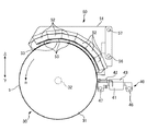
図1は、プリンタ1の全体構成を示すブロック図である。図2は、プリンタ1の主要部の構成を示した図である。図3は、ドラムユニット30、噴射部の一例であるヘッドユニット40、及び紫外線照射ユニット50の断面構造を示した図である。図4Aは、ヘッドユニット40を示した斜視図である。図4Bは、図4Aの矢印Fで示す方向からヘッド42を見たときの、ヘッド42の正面図である。図5は、紫外線照射ユニット50の斜視図である。
<<< Configuration of
FIG. 1 is a block diagram showing the overall configuration of the
外部装置であるコンピュータ110から印刷データを受信したプリンタ1は、コントローラ10により、各ユニット(給排紙ユニット20、ドラムユニット30、ヘッドユニット40、紫外線照射ユニット50、インク補給ユニット60)を制御し、用紙Sに画像を形成する(印刷処理)。また、プリンタ1内の状況を検出器群70が監視し、その検出結果に基づいて、コントローラ10は各ユニットを制御する。
The
コントローラ10は、プリンタ1の制御を行うための制御ユニット(制御部)である。インターフェース部11は、外部装置であるコンピュータ110とプリンタ1との間でデータの送受信を行うためのものである。CPU12は、プリンタ1全体の制御を行うための演算処理装置である。メモリ13は、CPU12のプログラムを格納する領域や作業領域等を確保するためのものである。CPU12は、メモリ13に格納されているプログラムに従ったユニット制御回路14により各ユニットを制御する。
The
給排紙ユニット20は、図2に示すように、給紙部21と排紙部22から成る。給紙部21は、用紙Sを搬送する給紙ローラ(不図示)を有し、給紙部21内に積層された用紙Sを一枚ずつドラムユニット30へ給紙する。排紙部22は、用紙Sを搬送する排紙ローラ(不図示)を有し、ドラムユニット30上に支持され印字が完了した用紙Sを、排紙部22内に送り込む。
As shown in FIG. 2, the paper supply /
ドラムユニット30は、給紙部21から給紙された用紙Sを保持する保持ドラム31を有する。この保持ドラム31の回転軸32は、一対のフレーム36に回転可能に支持されている。そして、保持ドラム31は、用紙Sを外周面33にて保持した状態で、図2に示す矢印Rの方向に回転する。
The
ヘッドユニット40は、一対のガイド軸46、47に支持され、保持ドラム31の軸方向において往復移動可能なヘッドキャリッジ41を有する。ヘッドキャリッジ41には、用紙Sにインクを噴射するヘッド42が設けられている。ここで、本実施例においては、ヘッド42として、互いに色の異なるインクを噴射する5個のヘッド42a〜42e(図4B)が、保持ドラム31に保持された用紙Sに対向するように設けられている。また、各ヘッド42a〜42eは、複数のノズルが形成されたノズルプレート44a〜44eを有し、各ノズルからインクが噴射される。また、各ノズルには、インクが入った圧力室(不図示)と、圧力室の容量を変化させてインクを噴射させるための駆動素子(ピエゾ素子)が設けられている。
The
また、ヘッドキャリッジ41には、インク(具体的には、顔料インク)を収容する収容室43a〜43e(図4A)が設けられている。各収容室43a〜43eは、対応するヘッド42a〜42eに供給されるインクを収容する。収容室43aはヘッド42aに供給されるクリアインクを、収容室43bはヘッド42bに供給されるイエローインクを、収容室43cはヘッド42cに供給されるマゼンタインクを、収容室43dはヘッド42dに供給されるシアンインクを、収容室43eはヘッド42eに供給されるブラックインクを、それぞれ収容する。なお、クリアインクは、無色透明なインクであり、イエロー、マゼンタ、シアン、及びブラックインクは、有色のインク(カラーインク)である。すなわち、ヘッドユニット40は、有色のインクと無色のインクとを用紙Sに噴射する。
The
また、本実施例においては、インクとして、紫外線が照射されることによって硬化する紫外線硬化型インクが用いられている。ここで、紫外線硬化型インクは、ビヒクル、光重合開始剤及び顔料の混合物に、消泡剤、重合禁止剤等の補助剤を添加して調合される。なお、ビヒクルは、光重合硬化性を有するオリゴマー、モノマー等を、反応性希釈剤により粘度調整して調合される。また、インクとしては、水性インクと油性インクの両方を含むものとする。 In this embodiment, an ultraviolet curable ink that is cured when irradiated with ultraviolet rays is used as the ink. Here, the ultraviolet curable ink is prepared by adding an auxiliary agent such as an antifoaming agent or a polymerization inhibitor to a mixture of a vehicle, a photopolymerization initiator and a pigment. The vehicle is prepared by adjusting the viscosity of a photopolymerization-curing oligomer, monomer or the like with a reactive diluent. The ink includes both water-based ink and oil-based ink.
紫外線照射ユニット50は、一対のガイド軸56、57に支持され、保持ドラム31の軸方向において往復移動可能な照射部キャリッジ51を有する。照射部キャリッジ51には、ヘッド42から噴射されて用紙Sに着弾したインクに対して紫外線を照射する照射部52が設けられている。照射部52は、保持ドラム31の回転方向に沿って整列された複数のランプ53を有する。このランプ53として、例えばメタルハライドランプが使用されている。そして、複数のランプ53が用紙S上のインクに紫外線を照射することによって、インクが硬化する。
The
インク補給ユニット60は、ヘッド42a〜42eによるインクの噴射に起因してヘッドユニット40(具体的には、収容室43a〜43e)内のインクの量が減った際に、収容室43a〜43eにインクを補給するためのものである。インク補給ユニット60は、インクカートリッジ61a〜61eを有している。インクカートリッジ61a〜61eは、対応する収容室43a〜43eに補給するインクを収容している(例えば、インクカートリッジ61aは、収容室43aに補給するクリアインクを収容する)。
When the amount of ink in the head unit 40 (specifically, the
<<<印刷処理>>>
コントローラ10は、コンピュータ110から印刷命令及び印刷データを受信すると、印刷データに含まれる各種コマンドの内容を解析し、各ユニットを用いて、以下の印刷処理を行う。
まず、給紙部21が、用紙Sを保持ドラム31に向かって給紙する。保持ドラム31に給紙された用紙Sは、外周面33に巻き付けられることによって保持される。そして、保持された用紙Sは、保持ドラム31と共に回転する。回転する用紙Sに対して、各ヘッド42はインクを噴射して着弾させる。用紙Sに着弾したインクは、保持ドラム31の回転に伴い移動して、照射部52によって紫外線が照射される。これにより、用紙S上のインクが硬化して、用紙S上に画像が形成される。
そして、保持ドラム31が1回転する際に保持ドラム31の軸方向の一部領域において用紙Sに画像が印刷されると、ヘッドキャリッジ41はガイド軸46、47に沿って移動する(照射部キャリッジ51も、同様にガイド軸56、57に沿って移動する)。そして、軸方向において上記領域に隣接した領域に対して、上述した動作(ヘッド42によるインクの噴射と、紫外線照射部52による紫外線の照射)が実行される。
このようにして、保持ドラム31の軸方向において全ての画像が印刷された用紙Sは、保持ドラム31から剥離されて、排紙部22に送り込まれる。これにより、印刷処理が終了する。
<<< Print processing >>>
Upon receiving a print command and print data from the
First, the
When an image is printed on the sheet S in a partial region in the axial direction of the holding
In this way, the paper S on which all images are printed in the axial direction of the holding
===光沢のある画像と、加飾性に富む画像===
プリンタ1を使用するユーザの嗜好等によって、光沢のある画像や、加飾性に富む画像の印刷の要望がある。そして、本実施形態に係るプリンタ1は、光沢のある画像と、加飾性に富む画像を印刷できる。
=== Glossy image and highly decorative image ===
Depending on the preference of the user who uses the
図6Aは、光沢のある画像を説明するための模式図である。図6Aに示す画像は、カラーインクをクリアインクで覆い被った画像である。この画像は、以下の手順にて印刷される。
まず、印刷する画像データに応じて、用紙S上にカラーインクを噴射させる。そして、用紙S上に着弾したカラーインクに紫外線を照射させて、当該カラーインクを硬化させる。その後(保持ドラム31が1回転した後)、用紙Sのほぼ全域に亘って(カラーインクを覆い被るように)、クリアインクを噴射させる。ここで、クリアインクは、カラーインクと馴染む性質を有する。このため、クリアインクがカラーインクと馴染んで、カラーインクを覆う平坦な層(当該層を、被覆層L1と呼ぶ)ができる。そして、このクリアインクに紫外線を照射させて、当該クリアインクを硬化させる。これにより、図6Aに示す画像が印刷される。クリアインクは無色透明なインクであるので、図6Aに示す画像は光沢のあるものとなる。
FIG. 6A is a schematic diagram for explaining a glossy image. The image shown in FIG. 6A is an image in which color ink is covered with clear ink. This image is printed according to the following procedure.
First, color ink is ejected onto the paper S in accordance with image data to be printed. Then, the color ink landed on the paper S is irradiated with ultraviolet rays to cure the color ink. Thereafter (after the holding
図6Bは、加飾性に富む画像を説明するための模式図である。図6Bに示す画像は、図6Aに示す画像(具体的には、被覆層L1)の上に、クリアインクによって凹凸(疑似エンボスとも呼ばれる)が形成された画像である。この画像は、以下の手順にて印刷される。
まず、図6Aに示す画像(被覆層L1を有する画像)を、前述した手順で形成する。次に、被覆層の上に、ほぼ全域に亘ってクリアインクを噴射する。ここで、紫外線が照射される前のクリアインクは、硬化後のクリアインク(被覆層を構成するクリアインク)に対しては馴染まない性質を有する。このため、クリアインクの噴射から時間が経つと、被覆層L1上のクリアインクが、凝集を開始する。そして、クリアインクの凝集開始後に、当該クリアインクに紫外線を照射することによって、被覆層L1の上に凹凸が形成される。形成された凹凸によってユーザは立体感を感じるようになるため、図6Bに示す画像は、全体として加飾性に富む画像となる。
FIG. 6B is a schematic diagram for explaining an image rich in decorating properties. The image illustrated in FIG. 6B is an image in which unevenness (also referred to as pseudo embossing) is formed with clear ink on the image illustrated in FIG. 6A (specifically, the coating layer L1). This image is printed according to the following procedure.
First, the image (image having the coating layer L1) shown in FIG. Next, clear ink is ejected over the entire area of the coating layer. Here, the clear ink before being irradiated with ultraviolet rays has a property that is not compatible with the cured clear ink (clear ink constituting the coating layer). For this reason, the clear ink on the coating layer L1 starts aggregating when time elapses from the ejection of the clear ink. Then, after the start of the aggregation of the clear ink, the clear ink is irradiated with ultraviolet rays, whereby irregularities are formed on the coating layer L1. Since the user feels a three-dimensional feeling due to the formed unevenness, the image shown in FIG. 6B is an image rich in decorating properties as a whole.
===光沢のある画像、及び加飾性に富む画像の印刷処理===
上述した光沢を有する画像や、加飾性に富む画像を実現すべく、プリンタ1は、画像形成方法として、以下に説明する第1印刷処理(第1動作に相当する)や第2印刷処理(第2動作に相当する)を実行する。そして、プリンタ1は、印刷する画像に応じて、第1印刷処理と第2印刷処理のうちの何れか一方を選択して実行する。
ここで、第1印刷処理は、光沢があり、かつ加飾性に富む画像を印刷する処理である。一方で、第2印刷処理は、光沢のある画像を印刷する処理である。以下においては、第1印刷処理の具体的な処理内容を説明した後に、第2印刷処理の具体的な処理内容を説明する。
=== Print processing of glossy image and image with rich decoration property ===
In order to realize the above-described glossy image or an image having a rich decorating property, the
Here, the first printing process is a process of printing an image having gloss and rich decoration. On the other hand, the second printing process is a process for printing a glossy image. In the following, after describing the specific processing contents of the first printing process, the specific processing contents of the second printing process will be described.
<<第1印刷処理>>
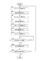
図7は、第1印刷処理を説明するためのフローチャートである。図8A〜図8Iは、用紙S上のインクの状態を示した模式図である。
なお、第1印刷処理が実行されるときのプリンタ1の各種動作は、主として、コントローラ10により実現される(第2印刷処理も同様である)。特に、本実施の形態においては、メモリ13に格納されたプログラムをCPU12が処理することにより実現される。そして、このプログラムは、以下に説明する各種の動作を行うためのコードから構成されている。
<< first printing process >>
FIG. 7 is a flowchart for explaining the first printing process. 8A to 8I are schematic diagrams showing the state of ink on the paper S. FIG.
Note that various operations of the
コンピュータ110から第1印刷処理の実行命令(印刷命令)を受信したコントローラ10は、まず、用紙Sにカラーインクを噴射させる(ステップS2)。すなわち、ヘッド42が、回転中の保持ドラム31に保持された用紙Sに対してカラーインクを噴射する。これにより、図8Aに示すように、用紙S上にカラーインクが着弾する。
The
そして、コントローラ10は、用紙Sを保持した保持ドラム31を更に回転させ、用紙S上に着弾したカラーインクに紫外線を照射させる(ステップS4)。すなわち、照射部52が、図8Bに示すように用紙S上のカラーインクに紫外線を照射する。これにより、カラーインクは、硬化する。
Then, the
次に、コントローラ10は、保持ドラム31を1回転させ、硬化したカラーインク上に、クリアインクを噴射させる(ステップS6)。具体的には、ヘッド42は、カラーインク上だけでなく、カラーインクが着弾していない用紙S上にも、クリアインクを噴射する。この結果、図8Cに示すように、着弾したクリアインクがカラーインクを覆い被る。
Next, the
そして、コントローラ10は、図8Dに示すように、クリアインクに紫外線を照射させる(ステップS8)。これにより、クリアインクが硬化し、カラーインクを覆う被覆層L1が形成され、この結果、光沢のある画像(この画像を、便宜上、印刷画像Pと呼ぶ)となる。なお、クリアインクは、着弾直後に紫外線を照射されるので、凝集せずに硬化する。このように、コントローラ10は、印刷画像Pを、用紙S上に着弾し紫外線が照射されたカラーインクの上に、クリアインクを噴射させ、クリアインクの凝集開始前に当該クリアインクに紫外線を照射させることにより、形成する。
Then, as shown in FIG. 8D, the
次に、コントローラ10は、保持ドラム31を1回転させ、図8Eに示すように印刷画像Pの被覆層L1(紫外線が照射されて硬化したクリアインク)の一部の上に、カラーインクを噴射させる(ステップS10)。これにより、用紙S上に、カラーインクが2層に亘って着弾することとなる。ここで、2層になるようにカラーインクが噴射される箇所は、例えば画像の濃度を濃くし、かつ発色度合いを大きくしたい箇所である。
Next, the
そして、コントローラ10は、ステップS4と同様にカラーインクに紫外線を照射させる(ステップS12)。すなわち、照射部52は、図8Fに示すように紫外線を照射して、カラーインクを硬化させる。
Then, the
次に、コントローラ10は、保持ドラム31を1回転させ、図8Gに示すように、紫外線が照射されて硬化したカラーインク、及び被覆層L1を構成するクリアインクの上に、クリアインクを更に噴射させる(ステップS14)。具体的には、ヘッド42は、印刷画像Pのほぼ全ての上にクリアインクを噴射する。
Next, the
ここで、噴射されたクリアインクは、カラーインクに対しては馴染む。すなわち、本実施形態のクリアインクは、カラーインクに対して親水性(親油性)を有する(なお、クリアインクは、用紙Sに対しても同様に親水性を有する)。一方で、噴射されたクリアインクは、被覆層L1を構成するクリアインクに対しては馴染まない。すなわち、クリアインクは、硬化後のクリアインクに対して撥水性(撥油性)を有する。このため、カラーインク上に着弾したクリアインクは、カラーインクに馴染んで、カラーインクを覆う被覆層を形成する(この被覆層によって、画像が更に光沢を有することとなる)。一方、被覆層L1(クリアインク)上に着弾したクリアインクは、時間が経過して、図8Hに示すように凝集を開始する。なお、インクの親水性と撥水性との関係は、本明細書中においては、親油性と撥油性との関係に相当する。 Here, the ejected clear ink becomes familiar with the color ink. That is, the clear ink according to the present embodiment has hydrophilicity (lipophilicity) with respect to the color ink (note that the clear ink has hydrophilicity with respect to the paper S as well). On the other hand, the ejected clear ink is not familiar with the clear ink constituting the coating layer L1. That is, the clear ink has water repellency (oil repellency) with respect to the clear ink after curing. For this reason, the clear ink that has landed on the color ink conforms to the color ink and forms a coating layer that covers the color ink (the coating layer makes the image more glossy). On the other hand, the clear ink that has landed on the coating layer L1 (clear ink) starts to aggregate as time passes, as shown in FIG. 8H. The relationship between the hydrophilicity and water repellency of the ink corresponds to the relationship between lipophilicity and oil repellency in the present specification.
次に、コントローラ10は、ステップS14のクリアインクの噴射から所定時間T(予め設定された時間)だけ経過したか否かを判断する(ステップS16)。ここで、前記所定時間Tは、予め実験等で測定された時間であり、クリアインクが凝集を開始したと推定できる時間である。このため、コントローラ10は、所定時間Tだけ経過した場合には、クリアインクが凝集したと判断し、所定時間Tの経過前には、クリアインクが凝集していないと判断する。なお、所定時間Tは、具体的には、保持ドラム31が例えば2回転(もちろん、3回転以上でも良い)する時間である。
Next, the
そして、所定時間Tが経過した場合には(ステップS16:Yes)、コントローラ10は、図8Iに示すように、凝集開始後のクリアインクに紫外線を照射させる(ステップS18)。すなわち、クリアインクの凝集開始後に、照射部52が、クリアインクに紫外線を照射する。そして、凝集開始後に紫外線を照射されたクリアインクが、硬化することにより、被覆層L1の上に凹凸(疑似エンボス)が形成されることとなる。
If the predetermined time T has elapsed (step S16: Yes), the
このように、コントローラ10は、印刷画像Pを構成する、紫外線が照射されて硬化したクリアインクの上に、クリアインクを更に噴射させ、クリアインクの凝集開始後に、クリアインクに紫外線を照射させる。これにより、被複層L1の上に疑似エンボスが形成されるため、加飾性に富む画像を印刷できる。
As described above, the
ところで、前記所定時間が長くなる(別言すれば、照射タイミングを遅くする)ほど、クリアインクの凝集度合いが進行するので、凹凸の凸の大きさが大きくなりやすい。そこで、照射タイミングを遅く設定することによって、凸を大きくできる。また、クリアインクの噴射量が多いほど、凹凸の凸の大きさが大きくなりやすい。そこで、クリアインクの噴射量を多く設定することによって、凸を大きくできる。このように、コントローラ10は、クリアインクの噴射量と、紫外線の照射タイミングとを変更することにより、クリアインクの凝集度合いを変更させて、被覆層L1上に形成される凸の大きさを調整できる。同様に、凸の発生間隔を調整できる。これにより、より加飾性に富む画像を印刷できる。
By the way, as the predetermined time becomes longer (in other words, the irradiation timing is delayed), the degree of aggregation of the clear ink progresses, so that the size of the unevenness tends to increase. Therefore, the convexity can be increased by setting the irradiation timing late. In addition, the larger the clear ink ejection amount, the larger the size of the unevenness. Therefore, the convexity can be increased by setting a large amount of clear ink to be ejected. As described above, the
なお、上述したステップS2〜S18の処理が実行されている間、ヘッドキャリッジ41と照射部キャリッジ51は、軸方向(図2)において同一位置に位置している。すなわち、用紙Sの軸方向における同一の領域に対して、カラーインクとクリアインクが噴射され、かつ、紫外線が照射される。
It should be noted that the
そして、更に用紙S上に画像を印刷する領域がある場合には(ステップS20:Yes)、コントローラ10は、ヘッドキャリッジ41と照射部キャリッジ51を軸方向に移動させて、例えば軸方向において既に印刷画像Pを印刷した領域に隣接する領域に対して、上述した動作(ステップS2〜S18)を繰り返す。一方で、印刷する領域が無い場合には(ステップS20:No)、コントローラ10は第1印刷処理を終了する。これにより、一枚の用紙Sの全ての領域に対する画像(光沢があり、かつ加飾性に富む画像)の印刷が完了することとなる。
If there is an area on the sheet S where an image is to be printed (step S20: Yes), the
<<第2印刷処理>>
図9は、第2印刷処理を説明するためのフローチャートである。図10A〜図10Dは、用紙S上のインクの状態を示した模式図である。
第2印刷処理においても、第1印刷処理のステップS2〜S12が実行される。すなわち、まず、コントローラ10は、図10Aに示すように用紙S上に印刷画像P(紫外線が照射されて硬化したカラーインク及び被覆層L1で構成される画像)を印刷する(図9のステップS2〜S8)。そして、コントローラ10は、図10Bに示すように被覆層L1の一部の上にカラーインクを更に噴射させた後(ステップS10)、図10Cに示すようにカラーインクに紫外線を照射させる(ステップS12)。
<< Second printing process >>
FIG. 9 is a flowchart for explaining the second printing process. 10A to 10D are schematic diagrams illustrating the state of ink on the paper S. FIG.
Also in the second printing process, steps S2 to S12 of the first printing process are executed. That is, first, as shown in FIG. 10A, the
次に、コントローラ10は、クリアインクを更に噴射させる(ステップS14)。ところで、第1印刷処理においては、カラーインク及び被覆層L1の全面上にクリアインクが噴射される(図8G参照)こととしたが、第2印刷処理においては、図10Dに示すようにカラーインクの上(カラーインクの近傍も含む)にクリアインクが噴射される。
Next, the
また、第2印刷処理では、クリアインクを凝集させる第1印刷処理(図8H参照)とは異なり、クリアインクを凝集させないこととしている。すなわち、コントローラ10は、第1印刷処理のステップS16の処理を実行しない。そして、コントローラ10は、ステップS14のクリアインクの噴射後に、図10Eに示すように凝集開始前にクリアインクに紫外線を照射させる(ステップS18)。これにより、クリアインクが凝集開始前に硬化することとなり、平坦な被覆層が形成される。
In the second printing process, unlike the first printing process (see FIG. 8H) in which the clear ink is aggregated, the clear ink is not aggregated. That is, the
そして、更に用紙S上に画像を印刷する領域がある場合には(ステップS20:Yes)、コントローラ10は、ヘッドキャリッジ41と照射部キャリッジ51を軸方向に移動させて、例えば軸方向において既に画像を印刷した領域に隣接する領域に対して、上述した動作(ステップS2〜S14、及びステップS18)を繰り返す。
If there is a region where an image is further printed on the paper S (step S20: Yes), the
第2印刷処理においては、被覆層L1の上にクリアインクによる凹凸が形成されない。一方、カラーインクが2層になって形成されていることにより、画像の濃度が濃くなって鮮やかな発色となるので、画質を向上できる。このように、加飾性のある画像よりも画質の向上を重視する画像を印刷する場合には、第2印刷処理を実行することにより、クリアインクの消費を低減でき、かつ、印刷速度の低下を抑制できる。 In the second printing process, the unevenness due to the clear ink is not formed on the coating layer L1. On the other hand, since the color ink is formed in two layers, the density of the image is increased and a vivid color is generated, so that the image quality can be improved. As described above, when printing an image in which improvement of image quality is more important than a decorative image, the consumption of clear ink can be reduced and the printing speed can be reduced by executing the second printing process. Can be suppressed.
===本実施形態に係るプリンタ1の有効性===
上述した印刷処理(第1印刷処理)においては、ヘッドユニット40によるインクの噴射動作と、照射部52による紫外線の照射動作とを制御するコントローラ10は、(1)用紙S上に着弾したカラーインクによって構成される印刷画像Pの上に、クリアインクを噴射させ、(2)印刷画像Pの上に着弾したクリアインクの凝集開始後に、クリアインクに紫外線を照射させる(図8A〜図8I参照)。これにより、以下に説明するように、加飾性に富む画像を実現することが可能となる。
すなわち、クリアインクが図8Hに示すように凝集することにより、印刷画像P(カラーインクと被覆層L1で構成された画像)の上に凹凸が形成されることになる。このため、図8Iに示すように、クリアインクの凝集開始後にクリアインクに紫外線を照射させることにより、最終的に凹凸がある画像(立体感のある画像)を印刷できる。この結果、加飾性に富む画像を実現できる。
=== Effectiveness of
In the above-described printing process (first printing process), the
That is, as the clear ink is aggregated as shown in FIG. 8H, irregularities are formed on the printed image P (image composed of the color ink and the coating layer L1). For this reason, as shown in FIG. 8I, an image with unevenness (an image with a three-dimensional effect) can be printed finally by irradiating the clear ink with ultraviolet rays after the start of aggregation of the clear ink. As a result, an image rich in decorating properties can be realized.
また、上述したように、コントローラ10は、紫外線が照射されて硬化したクリアインクの上に、クリアインクを更に噴射させ(図8G)、クリアインクの凝集開始後に、クリアインクに紫外線を照射させる(図8I)。これにより、効果的に凹凸がある画像を印刷できる。
すなわち、紫外線が照射される前のクリアインクは、硬化したクリアインクに対して馴染まない性質を有する(撥水性)。このため、硬化したクリアインクの上に着弾したクリアインクは、時間の経過とともに凝集し易い。この結果、印刷画像Pの上に凹凸を形成しやすいので、効果的に、凹凸がある画像を印刷できる。
Further, as described above, the
That is, the clear ink before being irradiated with ultraviolet rays has a property that is not compatible with the cured clear ink (water repellency). For this reason, the clear ink that has landed on the cured clear ink is likely to aggregate over time. As a result, since it is easy to form unevenness on the printed image P, an image with unevenness can be printed effectively.
また、上述したように、コントローラ10は、第1印刷処理と第2印刷処理を実行可能であり、第1印刷処理と第2印刷処理の何れか一方を選択して実行する。これにより、利便性の高いプリンタ1を実現できる。
すなわち、例えば画質を重視した画像(鮮やかな発色で光沢を有する画像)を印刷したい場合には、第2印刷処理を実行すれば良い。一方、加飾性に富む画像を印刷したい場合には、第1印刷処理を実行すれば良い。このように、印刷したい画像に応じた印刷処理を選択することにより、利便性の高いプリンタ1を実現できる。
Further, as described above, the
That is, for example, when it is desired to print an image that emphasizes image quality (image with vivid color and gloss), the second printing process may be executed. On the other hand, when it is desired to print an image rich in decorating properties, the first printing process may be executed. Thus, by selecting a printing process corresponding to an image to be printed, the highly
また、上述したように、コントローラ10は、紫外線が照射されて硬化したクリアインク(被覆層L1)の一部の上に、カラーインクを噴射させた(図8E)後に、当該カラーインクに紫外線を照射させる(図8F)。そして、コントローラ10は、紫外線が照射されて硬化したクリアインク及びカラーインクの上に、クリアインクを更に噴射させる(図8G)。更に、コントローラ10は、クリアインクの凝集開始後に、クリアインクに紫外線を照射させる(図8I)。これにより、画質が良く、かつ加飾性に富む画像を実現できる。
すなわち、硬化したクリアインク及びカラーインクの上に着弾したクリアインクのうち、クリアインクの上に着弾したクリアインクは、凝集して被覆層L1の上に凹凸(疑似エンボス)を形成する。一方で、カラーインクの上に着弾したクリアインクは、カラーインクと馴染んで平坦な被覆層を形成することにより、鮮やかな発色で光沢を有する画像を実現できる。従って、画質が良く、かつ加飾性に富む画像を実現できる。
Further, as described above, the
That is, of the clear ink that has landed on the cured clear ink and the color ink, the clear ink that has landed on the clear ink aggregates to form unevenness (pseudo embossing) on the coating layer L1. On the other hand, the clear ink that has landed on the color ink can realize a bright color and glossy image by forming a flat coating layer in accordance with the color ink. Therefore, it is possible to realize an image with good image quality and rich decoration.
===第2実施形態に係る印刷処理===
図11は、第2実施形態に係る印刷処理を説明するためのフローチャートである。図12A〜図12Dは、用紙S上のインクの状態を示した模式図である。
第2実施形態に係る印刷処理においては、上述した実施形態(以下、第1実施形態と呼ぶ)の印刷処理のステップS2〜S8(図7や図9)が実行される。すなわち、コントローラ10は、図12Aに示すように用紙S上に印刷画像P(紫外線が照射されて硬化したカラーインク及び被覆層L1で構成される画像)を印刷する(図11のステップS2〜S8)。
=== Print Processing According to Second Embodiment ===
FIG. 11 is a flowchart for explaining a printing process according to the second embodiment. 12A to 12D are schematic views showing the state of ink on the paper S. FIG.
In the printing process according to the second embodiment, steps S2 to S8 (FIGS. 7 and 9) of the printing process of the above-described embodiment (hereinafter referred to as the first embodiment) are executed. That is, as shown in FIG. 12A, the
ところで、第1実施形態においては、ヘッド42が被覆層L1の上にカラーインクを噴射することとしたが(図8E、図10B参照)、第2実施形態においては、ヘッド42がカラーインクを噴射しない。そして、コントローラ10は、被覆層L1(印刷画像P)の上にクリアインクのみを噴射させる(ステップS14)。すなわち、ヘッド42が、図12Bに示すようにクリアインクを被覆層L1のほぼ全域に亘って噴射する。ただし、これに限定されるものではなく、例えば被覆層L1の一部の上にクリアインクが噴射されることとしても良い。
By the way, in the first embodiment, the
次に、コントローラ10は、ステップS14のクリアインクの噴射から所定時間T(予め設定された時間)だけ経過したか否かを判断する(ステップS16)。ここで、所定時間Tが経過した場合には、前述したようにクリアインクが図12Cに示すように凝集を開始する。そして、所定時間Tが経過した場合には、コントローラ10は、図12Dに示すようにクリアインクに紫外線を照射させる(ステップS18)。すなわち、照射部52が、クリアインクの凝集開始後に、クリアインクに紫外線を照射する。この結果、被覆層L1の上に凹凸(疑似エンボス)が形成されることとなる。
Next, the
そして、更に用紙S上に画像を印刷する領域がある場合には(ステップS20:Yes)、コントローラ10は、ヘッドキャリッジ41と照射部キャリッジ51を軸方向に移動させて、例えば軸方向において既に印刷画像Pを印刷した領域に隣接する領域に対して、上述した動作(ステップS2〜S8、及びステップS14〜S18)を繰り返す。
If there is an area on the sheet S where an image is to be printed (step S20: Yes), the
本印刷処理によれば、第1実施形態の第1処理と同様に、被覆層L1上に疑似エンボスが形成されるため、加飾性に富む画像を印刷できる。特に、本印刷処理によれば、被複層L1のほぼ全域に亘って疑似エンボスを形成できるので、より加飾性に富む画像を印刷できることとなる。 According to this printing process, since the pseudo embossing is formed on the coating layer L1 as in the first process of the first embodiment, an image rich in decorating properties can be printed. In particular, according to the present printing process, pseudo embossing can be formed over almost the entire area of the multi-layer L1, and thus an image with more decorativeness can be printed.
===第3実施形態に係る印刷処理===
図13は、第3実施形態に係る印刷処理を説明するためのフローチャートである。図14A〜図14Eは、用紙S上のインクの状態を示した模式図である。
第3実施形態に係る印刷処理においては、第1実施形態とは異なり、被覆層L1を形成しない。すなわち、コントローラ10は、図14Aと図14Bに示すように用紙Sに着弾したカラーインクに対して紫外線を照射した後に(図13のステップS2、S4)、被覆層L1を形成するためのクリアインクを噴射しない。このため、第3実施形態においては、印刷画像Pは、ステップS2で噴射されたカラーインクのみによって構成されている。
=== Print Processing According to the Third Embodiment ===
FIG. 13 is a flowchart for explaining a printing process according to the third embodiment. 14A to 14E are schematic diagrams showing the state of ink on the paper S. FIG.
In the printing process according to the third embodiment, unlike the first embodiment, the coating layer L1 is not formed. That is, as shown in FIGS. 14A and 14B, the
ところで、第1実施形態と第2実施形態のクリアインクは、カラーインクに対して馴染む性質(親水性)を有することとした。一方で、第3実施形態のクリアインクは、カラーインクに対して馴染まない性質(撥水性)を有するものである。このため、カラーインクの上に着弾したクリアインクは、時間の経過に伴い、凝集することとなる。 By the way, the clear ink of 1st Embodiment and 2nd Embodiment decided to have the property (hydrophilicity) which adapts to color ink. On the other hand, the clear ink of the third embodiment has a property (water repellency) that is not compatible with color ink. For this reason, the clear ink that has landed on the color ink aggregates over time.
そして、カラーインクの上に凸(疑似エンボス)を形成するために、コントローラ10は、図14Cに示すように、紫外線が照射されて硬化したカラーインクの上にクリアインクを噴射させる(ステップS14)。
Then, in order to form a convex (pseudo emboss) on the color ink, as shown in FIG. 14C, the
次に、コントローラ10は、ステップS14のクリアインクの噴射から所定時間T(予め設定された時間であって、クリアインクが図14Dに示すようにカラーインク上で凝集開始すると推定される時間)だけ経過したか否かを判断する(ステップS16)。そして、所定時間Tが経過した場合には、コントローラ10は、図14Eに示すようにクリアインクに紫外線を照射させる(ステップS18)。すなわち、照射部52が、クリアインクの凝集開始後に、クリアインクに紫外線を照射する。この結果、カラーインクの上に凸(疑似エンボス)が形成されることとなる。
Next, the
本印刷処理によれば、第1実施形態の第1処理と同様に、カラーインク上に疑似エンボスが形成されるため、加飾性に富む画像を印刷できる。特に、本印刷処理によれば、被複層L1を形成しないので、クリアインクの消費を抑えられ、かつ、加飾性に富む画像を迅速に印刷できる。 According to this printing process, as in the first process of the first embodiment, pseudo embossing is formed on the color ink, so that an image rich in decorating properties can be printed. In particular, according to the present printing process, since the multi-layer L1 is not formed, consumption of clear ink can be suppressed, and an image rich in decorating properties can be printed quickly.
なお、本印刷処理においては、カラーインクの上のみにクリアインクを噴射させることとしたが、これに限定されるものではない。例えば、カラーインクの上を含む用紙Sのほぼ全域に亘って、クリアインクを噴射させることとしても良い。 In this printing process, the clear ink is ejected only on the color ink. However, the present invention is not limited to this. For example, the clear ink may be ejected over almost the entire area of the paper S including the color ink.
===その他の実施の形態===
以上、上記実施の形態に基づき本発明に係る流体噴射装置等を説明したが、上記した発明の実施の形態は、本発明の理解を容易にするためのものであり、本発明を限定するものではない。本発明は、その趣旨を逸脱することなく、変更、改良され得ると共に、本発明にはその等価物が含まれることはもちろんである。
=== Other Embodiments ===
The fluid ejecting apparatus and the like according to the present invention have been described above based on the above embodiment, but the above-described embodiment is for facilitating the understanding of the present invention and limits the present invention. is not. The present invention can be changed and improved without departing from the gist thereof, and the present invention includes the equivalents thereof.
前記実施形態では、流体噴射装置をインクジェットプリンタに具体化したが、この限りではなく、インク以外の他の液体(液体以外にも、機能材料の粒子が分散されている液状体、ジェルのような流状体を含む)や液体以外の流体(流体として流して噴射できる固体など)を噴射したり吐出したりする流体噴射装置に具体化することもできる。 In the above-described embodiment, the fluid ejecting apparatus is embodied in an ink jet printer. However, the present invention is not limited to this, and liquids other than ink (in addition to liquids, liquids in which functional material particles are dispersed, such as gels) It is also possible to embody a fluid ejecting apparatus that ejects or discharges a fluid other than a liquid (including a fluid) or a fluid (such as a solid that can be ejected as a fluid).
例えば、液晶ディスプレイ、EL(エレクトロルミネッセンス)ディスプレイ及び面発光ディスプレイの製造などに用いられる電極材や色材などの材料を分散または溶解のかたちで含む液状体を噴射する液状体噴射装置、バイオチップ製造に用いられる生体有機物を噴射する液体噴射装置、精密ピペットとして用いられ試料となる液体を噴射する液体噴射装置であってもよい。さらに、時計やカメラ等の精密機械にピンポイントで潤滑油を噴射する液体噴射装置、光通信素子等に用いられる微小半球レンズ(光学レンズ)などを形成するために紫外線硬化樹脂等の透明樹脂液を基板上に噴射する液体噴射装置、基板などをエッチングするために酸又はアルカリ等のエッチング液を噴射する液体噴射装置、ジェルを噴射する流状体噴射装置、トナーなどの粉体を例とする固体を噴射する粉体噴射式記録装置であってもよい。そして、これらのうちいずれか一種の噴射装置に本発明を適用することができる。 For example, a liquid material injection device for injecting a liquid material in the form of dispersed or dissolved materials such as electrode materials and color materials used in the manufacture of liquid crystal displays, EL (electroluminescence) displays, and surface-emitting displays, and biochip manufacturing It may be a liquid ejecting apparatus for ejecting a bio-organic substance used in the above, or a liquid ejecting apparatus for ejecting a liquid as a sample used as a precision pipette. In addition, transparent resin liquids such as UV curable resin to form liquid injection devices that pinpoint lubricant oil onto precision machines such as watches and cameras, and micro hemispherical lenses (optical lenses) used in optical communication elements. Examples include a liquid ejecting apparatus that ejects a liquid onto a substrate, a liquid ejecting apparatus that ejects an etching solution such as acid or alkali to etch the substrate, a fluid ejecting apparatus that ejects gel, and a powder such as toner. It may be a powder jet recording apparatus that jets a solid. The present invention can be applied to any one of these injection devices.
また、上記実施の形態において、照射部52は、メタルハライドランプであることとしたが、これに限定されるものではない。例えば、照射部52はLEDであることとしても良い。
Moreover, in the said embodiment, although the
また、インクの噴射方式としてピエゾ素子を利用するものに限られず、例えばサーマルプリンタなどにも適用できる。 Further, the ink ejection method is not limited to that using a piezo element, and can be applied to, for example, a thermal printer.
また、上記実施の形態において、照射部52とヘッド42がそれぞれ、別のキャリッジに設けられていることとしたが、これに限定されるものではない。例えば、照射部52とヘッド42が同一のキャリッジに設けられていることとしても良い。
In the above embodiment, the
また、上記の実施形態においては、回転する保持ドラム31に巻き付けられて保持された用紙Sにインクを噴射することとしたが、これに限定されるものではない。例えば、固定された支持部材(いわゆるプラテン)に支持された用紙S(この用紙Sは、搬送ローラ等によって搬送される)にインクを噴射することとしてもよい。
In the above embodiment, the ink is ejected onto the paper S that is wound around and held by the rotating holding
1 プリンタ、10 コントローラ、11 インターフェース、12 CPU、
13 メモリ、14 ユニット制御回路、15 タイマー、
20 給排紙ユニット、21 給紙部、22 排紙部、
30 ドラムユニット、31 保持ドラム、32 回転軸、33 外周面、
40 ヘッドユニット、41 ヘッドキャリッジ、42a〜42e ヘッド、
43a〜43e 収容室、44a〜44e ノズルプレート、
46 ガイド軸、47 ガイド軸、
50 紫外線照射ユニット、51 照射部キャリッジ、52 照射部、
53 ランプ、56 ガイド軸、57 ガイド軸、
60 インク補給ユニット、61a〜61e インクカートリッジ、
70 検出器群、110 コンピュータ
1 printer, 10 controller, 11 interface, 12 CPU,
13 memory, 14 unit control circuit, 15 timer,
20 paper feed / discharge unit, 21 paper feed unit, 22 paper discharge unit,
30 drum unit, 31 holding drum, 32 rotating shaft, 33 outer peripheral surface,
40 head unit, 41 head carriage, 42a to 42e head,
43a-43e storage chamber, 44a-44e nozzle plate,
46 guide shaft, 47 guide shaft,
50 UV irradiation unit, 51 irradiation unit carriage, 52 irradiation unit,
53 lamp, 56 guide shaft, 57 guide shaft,
60 ink supply unit, 61a to 61e ink cartridge,
70 detector groups, 110 computers
Claims (6)
前記媒体上の流体に紫外線を照射して前記流体を硬化させる照射部と、
前記噴射部による流体の噴射動作と、前記照射部による前記紫外線の照射動作とを制御するための制御部であって、
前記媒体上に着弾した前記有色の流体によって構成される画像の上に、前記無色の流体を噴射させ、
前記画像の上に着弾した前記無色の流体の凝集開始後に、前記無色の流体に前記紫外線を照射させる制御部と、
を備えることを特徴とする流体噴射装置。 An ejection unit that ejects a colored fluid and a colorless fluid onto a medium;
An irradiation unit for irradiating the fluid on the medium with ultraviolet rays to cure the fluid;
A control unit for controlling a fluid ejection operation by the ejection unit and an ultraviolet irradiation operation by the irradiation unit;
Spraying the colorless fluid on an image composed of the colored fluid landed on the medium;
A controller that irradiates the colorless fluid with the ultraviolet light after the colorless fluid that has landed on the image starts to aggregate;
A fluid ejecting apparatus comprising:
前記制御部は、
前記画像を、前記媒体上に着弾し前記紫外線が照射された前記有色の流体の上に、前記無色の流体を噴射させ、前記無色の流体の凝集開始前に当該無色の流体に前記紫外線を照射させることにより、形成し、
前記紫外線が照射されて硬化した前記無色の流体の上に、前記無色の流体を更に噴射させ、
前記無色の流体の凝集開始後に、前記無色の流体に前記紫外線を照射させることを特徴とする流体噴射装置。 The fluid ejection device according to claim 1,
The controller is
The colorless fluid is ejected onto the colored fluid that has landed on the medium and irradiated with the ultraviolet light, and the colorless fluid is irradiated with the ultraviolet light before the colorless fluid starts to aggregate. By forming and
The colorless fluid is further ejected onto the colorless fluid cured by being irradiated with the ultraviolet rays,
The fluid ejecting apparatus, wherein the colorless fluid is irradiated with the ultraviolet light after the colorless fluid starts to aggregate.
前記制御部は、
前記画像を構成する、前記紫外線が照射されて硬化した前記無色の流体の上に、前記無色の流体を更に噴射させ、
前記無色の流体の凝集開始後に、前記無色の流体に前記紫外線を照射させる第1動作と、
前記画像を構成する、前記紫外線が照射されて硬化した前記無色の流体の一部の上に、前記有色の流体を噴射させた後に、当該有色の流体に前記紫外線を照射させ、
紫外線が照射された前記有色の流体の上に前記無色の流体を更に噴射させた後に、前記無色の流体の凝集開始前に当該無色の流体に紫外線を照射させる第2動作と、
を実行可能であり、
前記第1動作と第2動作のうちの何れか一方を選択して実行することを特徴とする流体噴射装置。 The fluid ejecting apparatus according to claim 2,
The controller is
The colorless fluid is further jetted onto the colorless fluid that is cured by being irradiated with the ultraviolet rays, constituting the image.
A first operation of irradiating the colorless fluid with the ultraviolet light after the colorless fluid starts to aggregate;
After the colored fluid is ejected onto a part of the colorless fluid that is cured by being irradiated with the ultraviolet rays, constituting the image, the colored fluid is irradiated with the ultraviolet rays,
A second operation of irradiating the colorless fluid with ultraviolet rays before the colorless fluid starts to aggregate after further injecting the colorless fluid onto the colored fluid irradiated with ultraviolet rays;
Is possible and
One of the first operation and the second operation is selected and executed.
前記制御部は、
前記画像を、前記媒体上に着弾し前記紫外線が照射された前記有色の流体の上に、前記無色の流体を噴射させ、前記無色の流体の凝集開始前に当該無色の流体に前記紫外線を照射させることにより、形成し、
前記紫外線が照射されて硬化した前記無色の流体の一部の上に、前記有色の流体を噴射させた後に、当該有色の流体に前記紫外線を照射させ、
前記紫外線が照射されて硬化した前記無色の流体及び前記有色の流体の上に、前記無色の流体を更に噴射させ、
前記無色の流体の凝集開始後に、前記無色の流体に前記紫外線を照射させることを特徴とする流体噴射装置。 The fluid ejection device according to claim 1,
The controller is
The colorless fluid is ejected onto the colored fluid that has landed on the medium and irradiated with the ultraviolet light, and the colorless fluid is irradiated with the ultraviolet light before the colorless fluid starts to aggregate. By forming and
After spraying the colored fluid onto a part of the colorless fluid that has been cured by being irradiated with the ultraviolet rays, the colored fluid is irradiated with the ultraviolet rays,
The colorless fluid is further ejected onto the colorless fluid and the colored fluid cured by being irradiated with the ultraviolet rays,
The fluid ejecting apparatus, wherein the colorless fluid is irradiated with the ultraviolet light after the colorless fluid starts to aggregate.
凝集開始後に前記紫外線を照射された前記無色の流体は、硬化することにより、前記画像の上に凸が形成され、
前記制御部は、前記無色の流体の噴射量と前記紫外線の照射タイミングとを変更することにより、前記無色の流体の凝集度合いを変更させて、形成される前記凸の大きさを調整することを特徴とする流体噴射装置。 The fluid ejection device according to any one of claims 1 to 4,
The colorless fluid irradiated with the ultraviolet light after the start of aggregation is cured to form a convex on the image,
The controller changes the degree of aggregation of the colorless fluid by changing the injection amount of the colorless fluid and the irradiation timing of the ultraviolet light, and adjusts the size of the convex formed. A fluid ejecting apparatus.
前記画像の上に着弾した前記無色の流体の凝集開始後に、前記無色の流体に紫外線を照射して当該無色の流体を硬化させることと、
を有することを特徴とする画像形成方法。 Spraying a colorless fluid onto an image composed of colored fluid landed on a medium;
After the colorless fluid that has landed on the image starts to aggregate, irradiating the colorless fluid with ultraviolet rays to cure the colorless fluid;
An image forming method comprising:
Priority Applications (3)
| Application Number | Priority Date | Filing Date | Title |
|---|---|---|---|
| JP2008171456A JP5040832B2 (en) | 2008-06-30 | 2008-06-30 | Fluid ejecting apparatus and image forming method |
| US12/490,521 US8240837B2 (en) | 2008-06-30 | 2009-06-24 | Fluid ejecting apparatus and image formation method |
| US13/307,880 US8465145B2 (en) | 2008-06-30 | 2011-11-30 | Fluid ejecting apparatus and image formation method |
Applications Claiming Priority (1)
| Application Number | Priority Date | Filing Date | Title |
|---|---|---|---|
| JP2008171456A JP5040832B2 (en) | 2008-06-30 | 2008-06-30 | Fluid ejecting apparatus and image forming method |
Publications (2)
| Publication Number | Publication Date |
|---|---|
| JP2010006027A JP2010006027A (en) | 2010-01-14 |
| JP5040832B2 true JP5040832B2 (en) | 2012-10-03 |
Family
ID=41446852
Family Applications (1)
| Application Number | Title | Priority Date | Filing Date |
|---|---|---|---|
| JP2008171456A Active JP5040832B2 (en) | 2008-06-30 | 2008-06-30 | Fluid ejecting apparatus and image forming method |
Country Status (2)
| Country | Link |
|---|---|
| US (2) | US8240837B2 (en) |
| JP (1) | JP5040832B2 (en) |
Families Citing this family (20)
| Publication number | Priority date | Publication date | Assignee | Title |
|---|---|---|---|---|
| FR2952583B1 (en) * | 2009-11-19 | 2013-01-25 | Mgi France | SYSTEM AND METHOD FOR DEPOSITING SOLIDIFIABLE TRANSLUCENT FLUID WITH A DETERMINED THICKNESS |
| JP5413155B2 (en) * | 2009-11-30 | 2014-02-12 | セイコーエプソン株式会社 | Printing system, printing control program, and printing method |
| JP5539122B2 (en) * | 2010-08-31 | 2014-07-02 | キヤノン株式会社 | Image processing method and image processing apparatus |
| JP2012056155A (en) * | 2010-09-08 | 2012-03-22 | Seiko Epson Corp | Image forming apparatus and computer program |
| JP5790117B2 (en) * | 2011-04-20 | 2015-10-07 | セイコーエプソン株式会社 | Printing apparatus, printing method, and program |
| JP5811589B2 (en) * | 2011-05-18 | 2015-11-11 | セイコーエプソン株式会社 | Printing apparatus and printing method |
| JP5780012B2 (en) * | 2011-06-28 | 2015-09-16 | セイコーエプソン株式会社 | Printing apparatus and printing method |
| US20130077998A1 (en) * | 2011-09-27 | 2013-03-28 | Thomas Nathaniel Tombs | Electrographic printing using fluidic charge dissipation |
| US20130077999A1 (en) * | 2011-09-27 | 2013-03-28 | Thomas Nathaniel Tombs | Electrographic printer using fluidic charge dissipation |
| JP5988641B2 (en) * | 2012-03-23 | 2016-09-07 | キヤノン株式会社 | Printer device, printing method, program. |
| JP2013226481A (en) * | 2012-04-24 | 2013-11-07 | Great Computer Corp | Method for forming surface with irregular transparent matting particle by uv inkjet printer and finished printed mater made by uv inkjet printer |
| WO2014048734A1 (en) | 2012-09-26 | 2014-04-03 | Oce-Technologies B.V. | Method of applying a curable liquid and apparatus for performing this method |
| EP2810783B1 (en) * | 2013-06-03 | 2015-10-21 | Hewlett-Packard Industrial Printing Ltd. | Inkjet printing method |
| JP2015074120A (en) * | 2013-10-07 | 2015-04-20 | 株式会社ミマキエンジニアリング | Ink jet printing method |
| JP6435638B2 (en) * | 2014-05-16 | 2018-12-12 | 株式会社リコー | Inkjet recording apparatus, inkjet recording method and program |
| JP2016013671A (en) * | 2014-07-03 | 2016-01-28 | キヤノン株式会社 | Convexoconcave formation device and convexoconcave formation method |
| JPWO2016088873A1 (en) * | 2014-12-05 | 2017-09-28 | コニカミノルタ株式会社 | Image forming method |
| FR3033506B1 (en) * | 2015-03-11 | 2020-02-21 | Reydel Automotive B.V. | METHOD AND INSTALLATION FOR COATING A BODY WITH THE FORMATION OF A STRUCTURED SURFACE |
| KR102128222B1 (en) * | 2016-02-05 | 2020-06-29 | 나이키 이노베이트 씨.브이. | Additive color printing using multiple color graphic layers |
| JP7415431B2 (en) | 2018-11-30 | 2024-01-17 | 株式会社リコー | Liquid discharge device, program and discharge control method |
Family Cites Families (7)
| Publication number | Priority date | Publication date | Assignee | Title |
|---|---|---|---|---|
| JP3243700B2 (en) * | 1993-06-25 | 2002-01-07 | 大日本印刷株式会社 | Synchronized embossed decorative sheet |
| EP1167046B1 (en) * | 2000-06-21 | 2006-05-17 | Canon Kabushiki Kaisha | Ink jet recording apparatus and printing method thereof |
| JP2003191594A (en) | 2001-12-26 | 2003-07-09 | Konica Corp | Image forming method, ink, final printed matter and recording apparatus |
| JP4244382B2 (en) * | 2003-02-26 | 2009-03-25 | セイコーエプソン株式会社 | Functional material fixing method and device manufacturing method |
| JP4531405B2 (en) * | 2004-01-13 | 2010-08-25 | ローランドディー.ジー.株式会社 | Ink jet printer and printing method |
| US7510277B2 (en) * | 2004-03-01 | 2009-03-31 | Fujifilm Corporation | Image forming apparatus and method |
| JP2006015691A (en) * | 2004-07-05 | 2006-01-19 | Mimaki Engineering Co Ltd | Printing method with ink-jet printer using uv-curing ink and the same printer using in the method |
-
2008
- 2008-06-30 JP JP2008171456A patent/JP5040832B2/en active Active
-
2009
- 2009-06-24 US US12/490,521 patent/US8240837B2/en active Active
-
2011
- 2011-11-30 US US13/307,880 patent/US8465145B2/en active Active
Also Published As
| Publication number | Publication date |
|---|---|
| JP2010006027A (en) | 2010-01-14 |
| US20090322804A1 (en) | 2009-12-31 |
| US8465145B2 (en) | 2013-06-18 |
| US20120069073A1 (en) | 2012-03-22 |
| US8240837B2 (en) | 2012-08-14 |
Similar Documents
| Publication | Publication Date | Title |
|---|---|---|
| JP5040832B2 (en) | Fluid ejecting apparatus and image forming method | |
| US8585198B2 (en) | Printing apparatus and printing method | |
| JP2009096187A (en) | Image forming method and inkjet recording apparatus | |
| JP6485183B2 (en) | Printing device | |
| JP2006212881A (en) | Image forming apparatus | |
| JP2018069707A (en) | Inkjet printer and inkjet printing method | |
| EP3517307A1 (en) | Printing apparatus and printing method | |
| JP5196524B2 (en) | Image forming method and image forming apparatus | |
| JP2005262553A (en) | Image recording apparatus | |
| JP2009051118A (en) | Inkjet recording device and recording method | |
| JP2010083139A (en) | Fluid jet apparatus and image forming method | |
| US8449064B2 (en) | Liquid ejecting apparatus, method and program of controlling fluid ejecting apparatus, and target | |
| JP2010083140A (en) | Fluid jet apparatus and image forming method | |
| JP6641890B2 (en) | Printing apparatus and printing method | |
| JP5040724B2 (en) | Fluid ejection device and pressurization control method | |
| JP7384688B2 (en) | inkjet printer | |
| JP2004122534A (en) | Inkjet recording device and inkjet recording method | |
| JP5169319B2 (en) | Rotating body control device | |
| JP5332564B2 (en) | Liquid ejection apparatus and liquid ejection method | |
| US9969186B1 (en) | Inkjet printer | |
| US20230406008A1 (en) | Printer apparatus and print method for preparing an image having matt portions and glossy portions | |
| EP3069885B1 (en) | Recording apparatus | |
| JP2010052142A (en) | Liquid jet apparatus and liquid jet method | |
| JP2010167675A (en) | Image forming apparatus and method for adjusting deviation of striking position | |
| JP2017193113A (en) | Inkjet recording device and image forming method of inkjet recording device |
Legal Events
| Date | Code | Title | Description |
|---|---|---|---|
| RD03 | Notification of appointment of power of attorney |
Free format text: JAPANESE INTERMEDIATE CODE: A7423 Effective date: 20110316 |
|
| RD04 | Notification of resignation of power of attorney |
Free format text: JAPANESE INTERMEDIATE CODE: A7424 Effective date: 20110316 |
|
| A621 | Written request for application examination |
Free format text: JAPANESE INTERMEDIATE CODE: A621 Effective date: 20110328 |
|
| A977 | Report on retrieval |
Free format text: JAPANESE INTERMEDIATE CODE: A971007 Effective date: 20120531 |
|
| TRDD | Decision of grant or rejection written | ||
| A01 | Written decision to grant a patent or to grant a registration (utility model) |
Free format text: JAPANESE INTERMEDIATE CODE: A01 Effective date: 20120612 |
|
| A01 | Written decision to grant a patent or to grant a registration (utility model) |
Free format text: JAPANESE INTERMEDIATE CODE: A01 |
|
| A61 | First payment of annual fees (during grant procedure) |
Free format text: JAPANESE INTERMEDIATE CODE: A61 Effective date: 20120625 |
|
| R150 | Certificate of patent or registration of utility model |
Ref document number: 5040832 Country of ref document: JP Free format text: JAPANESE INTERMEDIATE CODE: R150 Free format text: JAPANESE INTERMEDIATE CODE: R150 |
|
| FPAY | Renewal fee payment (event date is renewal date of database) |
Free format text: PAYMENT UNTIL: 20150720 Year of fee payment: 3 |
|
| S531 | Written request for registration of change of domicile |
Free format text: JAPANESE INTERMEDIATE CODE: R313531 |
|
| R350 | Written notification of registration of transfer |
Free format text: JAPANESE INTERMEDIATE CODE: R350 |