JP5040576B2 - Detection device and recording device - Google Patents
Detection device and recording device Download PDFInfo
- Publication number
- JP5040576B2 JP5040576B2 JP2007268355A JP2007268355A JP5040576B2 JP 5040576 B2 JP5040576 B2 JP 5040576B2 JP 2007268355 A JP2007268355 A JP 2007268355A JP 2007268355 A JP2007268355 A JP 2007268355A JP 5040576 B2 JP5040576 B2 JP 5040576B2
- Authority
- JP
- Japan
- Prior art keywords
- recording
- signal
- digital signal
- unit
- detection
- Prior art date
- Legal status (The legal status is an assumption and is not a legal conclusion. Google has not performed a legal analysis and makes no representation as to the accuracy of the status listed.)
- Expired - Fee Related
Links
- 238000001514 detection method Methods 0.000 title claims description 115
- 238000004140 cleaning Methods 0.000 claims description 47
- 230000000630 rising effect Effects 0.000 claims description 16
- 230000001360 synchronised effect Effects 0.000 claims description 13
- 230000032258 transport Effects 0.000 description 16
- 238000011109 contamination Methods 0.000 description 12
- 230000035945 sensitivity Effects 0.000 description 7
- 238000010586 diagram Methods 0.000 description 6
- 230000033001 locomotion Effects 0.000 description 5
- 239000000428 dust Substances 0.000 description 4
- 230000002159 abnormal effect Effects 0.000 description 3
- 230000005856 abnormality Effects 0.000 description 3
- 230000007423 decrease Effects 0.000 description 3
- 238000000034 method Methods 0.000 description 3
- 239000003595 mist Substances 0.000 description 3
- 239000011347 resin Substances 0.000 description 2
- 229920005989 resin Polymers 0.000 description 2
- 230000007704 transition Effects 0.000 description 2
- YCKRFDGAMUMZLT-UHFFFAOYSA-N Fluorine atom Chemical compound [F] YCKRFDGAMUMZLT-UHFFFAOYSA-N 0.000 description 1
- 239000004642 Polyimide Substances 0.000 description 1
- 238000005299 abrasion Methods 0.000 description 1
- 238000010521 absorption reaction Methods 0.000 description 1
- 230000001133 acceleration Effects 0.000 description 1
- 230000003321 amplification Effects 0.000 description 1
- 230000005540 biological transmission Effects 0.000 description 1
- 230000000694 effects Effects 0.000 description 1
- 239000002657 fibrous material Substances 0.000 description 1
- 229910052731 fluorine Inorganic materials 0.000 description 1
- 239000011737 fluorine Substances 0.000 description 1
- 239000000463 material Substances 0.000 description 1
- 239000004745 nonwoven fabric Substances 0.000 description 1
- 238000003199 nucleic acid amplification method Methods 0.000 description 1
- 239000005020 polyethylene terephthalate Substances 0.000 description 1
- 229920001721 polyimide Polymers 0.000 description 1
- 239000011148 porous material Substances 0.000 description 1
- 239000000843 powder Substances 0.000 description 1
- 238000011084 recovery Methods 0.000 description 1
Images


Classifications
-
- B—PERFORMING OPERATIONS; TRANSPORTING
- B41—PRINTING; LINING MACHINES; TYPEWRITERS; STAMPS
- B41J—TYPEWRITERS; SELECTIVE PRINTING MECHANISMS, i.e. MECHANISMS PRINTING OTHERWISE THAN FROM A FORME; CORRECTION OF TYPOGRAPHICAL ERRORS
- B41J11/00—Devices or arrangements of selective printing mechanisms, e.g. ink-jet printers or thermal printers, for supporting or handling copy material in sheet or web form
- B41J11/007—Conveyor belts or like feeding devices
-
- B—PERFORMING OPERATIONS; TRANSPORTING
- B41—PRINTING; LINING MACHINES; TYPEWRITERS; STAMPS
- B41J—TYPEWRITERS; SELECTIVE PRINTING MECHANISMS, i.e. MECHANISMS PRINTING OTHERWISE THAN FROM A FORME; CORRECTION OF TYPOGRAPHICAL ERRORS
- B41J19/00—Character- or line-spacing mechanisms
- B41J19/18—Character-spacing or back-spacing mechanisms; Carriage return or release devices therefor
- B41J19/20—Positive-feed character-spacing mechanisms
- B41J19/202—Drive control means for carriage movement
- B41J19/205—Position or speed detectors therefor
Landscapes
- Accessory Devices And Overall Control Thereof (AREA)
- Ink Jet (AREA)
Description
本発明は、移動体の移動方向に沿って被検出要素が配列されて成る被検出部、および前記移動体の移動に伴い前記被検出要素を検出し、その検出感度に応じた出力レベルの波形信号を出力する検出部、を備えた検出装置に関する。 The present invention relates to a detected portion in which detected elements are arranged along the moving direction of a moving body, and a waveform of an output level corresponding to the detection sensitivity, which detects the detected elements as the moving body moves. The present invention relates to a detection device including a detection unit that outputs a signal.
また本発明は、ファクシミリやプリンタ等に代表される記録装置、その中でも特に被記録媒体の搬送方向に移動する搬送面を形成する搬送ベルトによって被記録媒体を搬送するよう構成された記録装置に関する。 The present invention also relates to a recording apparatus represented by a facsimile, a printer, and the like, and more particularly to a recording apparatus configured to convey a recording medium by a conveyance belt that forms a conveyance surface that moves in the conveyance direction of the recording medium.
ファクシミリやプリンタ等に代表される記録装置には、動体の動作量や動作速度を検出する為の検出手段、例えば、記録ヘッドを搭載したキャリッジ、被記録媒体を搬送する搬送ベルト、被記録媒体を搬送する搬送ローラ、などの動作量や動作速度を検出する検出手段が設けられる。 In a recording apparatus represented by a facsimile, a printer, or the like, a detecting means for detecting an operation amount and an operation speed of a moving body, for example, a carriage equipped with a recording head, a conveying belt for conveying a recording medium, and a recording medium are provided. Detection means for detecting an operation amount and an operation speed of a conveyance roller for conveyance is provided.
検出手段には、非接触式や接触式のものがあり、非接触式のものでは、例えば光透過部及び光遮蔽部を被検出要素として、これらを交互に配列して成る被検出部としてのリニアスケール或いはロータリースケールと、動体の動作に伴い前記光透過部及び前記光遮蔽部を検出して波形信号を出力する検出部とを備えて構成される検出装置がある。また接触式のものでは、S極とN極の磁極を交互に配列して成る磁気記録層と、動体の動作に伴い前記磁気記録層の磁極の変化を検出して波形信号を出力する検出部を備えて構成される検出装置がある。 The detection means includes a non-contact type and a contact type. In the non-contact type, for example, a light transmitting part and a light shielding part are used as detection elements, and these are alternately arranged as a detection part. There is a detection device configured to include a linear scale or a rotary scale, and a detection unit that detects the light transmission unit and the light shielding unit and outputs a waveform signal in accordance with the operation of a moving body. In the contact type, a magnetic recording layer in which S poles and N poles are alternately arranged, and a detection unit that detects a change in the magnetic poles of the magnetic recording layer in accordance with the operation of the moving body and outputs a waveform signal. There exists a detection apparatus comprised with.
ここで、インクを吐出することにより被記録媒体に記録を行うインクジェットプリンタにおいては、ミストとなって浮遊するインクが被検出要素に付着することにより、被検出要素を検出できなくなる場合がある。また、インクジェット式の記録装置以外においても、用紙搬送経路上で発生した紙粉や、摺動部分から発生した摩耗粉、外部から侵入した塵埃等が、被検出要素に付着して被検出要素を検出できなくなる場合がある。 Here, in an ink jet printer that performs recording on a recording medium by ejecting ink, the detected element may not be detected due to the mist floating and adhering to the detected element. Also, other than the ink jet recording apparatus, paper dust generated on the paper transport path, abrasion powder generated from the sliding part, dust entering from the outside, etc. adheres to the detected element and It may not be detected.
この様な技術的課題を前提に成された発明として、特許文献1には、エンコーダ信号の異常を検出する手段を設け、エンコーダ信号が正常に出力されていないことが検出されると、キャリッジを駆動するモータの駆動を停止させ、これによってキャリッジの暴走を防止するシリアルプリンタが記載されている。
As an invention made on the assumption of such a technical problem,
また特許文献2には、リニアエンコーダセンサの汚れを検出すると、リニアエンコーダセンサの清掃を行う記録装置が記載されている。また特許文献3には、キャリッジの位置信号の欠落や変動を補償して正常な印字制御を行うよう構成された画像形成装置が記載されている。
更に特許文献4には、エンコーダ汚れと判定した場合には、操作パネルに設けた表示手段等に異常情報を送信して、ユーザにエンコーダ汚れが発生している旨を通知し、警告する画像形成装置が記載されている。
Further, in
また更に特許文献5には、エンコーダ目盛板のスリット中点位置を、受光器が出力する電気信号の分布の中点位置を求めることによって把握する際に、前記電気信号の出力レベルに対して2つの閾値を用い、それぞれの閾値により得られた中点位置の平均を求め、その平均値をスリット中点位置とするエンコーダが記載されている。 Furthermore, in Patent Document 5, when the midpoint position of the slit of the encoder scale plate is grasped by obtaining the midpoint position of the distribution of the electric signal output by the light receiver, 2 is output for the output level of the electric signal. An encoder is described in which two threshold values are used, the average of the midpoint positions obtained by the respective threshold values is obtained, and the average value is used as the slit midpoint position.
そしてこのエンコーダにおいては、エンコーダ目盛板が汚れていたりゴミ等の異物が付着して前記電気信号の分布が歪み、これによって2つの閾値により求められた前記電気信号の分布の中点位置の差が所定値以上となる場合には、それぞれの閾値により得られた中点位置を、スリット中点位置を決定するのに用いないようにし、誤差を可及的に小さくしている。
以上のように被検出要素の汚れに起因する問題点を解決するための発明は種々存在していたものの、なおも以下の技術的課題があった。即ち、特許文献1記載のシリアルプリンタにおいては、エンコーダ信号が正常に出力されていないことが検出されると、キャリッジを駆動するモータの駆動を停止させるので、印字動作が途中で中止されることによって記録紙に無駄が生じる。そしてこの様な技術的課題及びこれを解決する手段については、特許文献2、3、5にも記載されていない。
As described above, although there have been various inventions for solving the problems caused by the contamination of the element to be detected, there are still the following technical problems. That is, in the serial printer described in
尚、特許文献4記載の画像形成装置は、エンコーダスケールの同一箇所で複数回速度異常値が発生した場合にのみエンコーダ汚れと判定することによって、汚れの程度が軽い状態ではすぐに装置を使用不可にしないようにしている。
Note that the image forming apparatus described in
しかしエンコーダスケールの同一箇所で複数回速度異常値が発生した場合には、印刷実行を中止してキャリッジ原点合わせ動作を行い、原点合わせ終了後残りの印刷を実行するので、印刷実行の中止の際用紙に無駄が生じる虞がある。或いは、或る用紙への印刷を途中で中止し、キャリッジ原点合わせ動作を行い、その後に印刷を再開した場合には、記録品質が著しく低下する虞がある。 However, if an abnormal speed value occurs multiple times at the same position on the encoder scale, the print execution is stopped and the carriage origin adjustment operation is performed, and the remaining printing is executed after the origin adjustment is completed. There is a risk that paper will be wasted. Alternatively, when printing on a certain sheet is stopped halfway, a carriage origin alignment operation is performed, and then printing is resumed, there is a possibility that the recording quality may be significantly lowered.
そこで本発明はこの様な状況に鑑みなされたものであり、その目的は、被検出要素の汚れが生じた場合であっても記録実行中の用紙を無駄にすることなく、且つ記録品質の低下も招くことのない検出装置を提供することにある。 Accordingly, the present invention has been made in view of such a situation, and an object of the present invention is to reduce the recording quality without wasting the paper being recorded even when the detected element is contaminated. It is another object of the present invention to provide a detection device that does not incur.
上記課題を解決する為に、本発明の第1の態様に係る検出装置は、動体の動作方向に沿って被検出要素が配列されて成る被検出部と、前記動体の動作に伴い前記被検出要素を検出し、その検出感度に応じた出力レベルの波形信号を出力する検出部と、前記波形信号を第1閾値に基づき二値化して第1デジタル信号を出力する第1デジタル信号出力部と、前記波形信号を前記第1閾値より絶対値の高い第2閾値に基づき二値化して第2デジタル信号を出力する第2デジタル信号出力部と、前記第2デジタル信号に状態変化が生じているか否かを判定する判定部とを備えたことを特徴とする。 In order to solve the above-described problem, a detection device according to a first aspect of the present invention includes a detection unit in which detection target elements are arranged along an operation direction of a moving object, and the detection target according to the operation of the moving object. A detection unit that detects an element and outputs a waveform signal having an output level corresponding to the detection sensitivity; a first digital signal output unit that binarizes the waveform signal based on a first threshold value and outputs a first digital signal; A second digital signal output unit that binarizes the waveform signal based on a second threshold value that is higher in absolute value than the first threshold value and outputs a second digital signal; and whether a state change occurs in the second digital signal And a determination unit for determining whether or not.
本発明の検出装置は、検出部が出力する波形信号の出力レベルに対する閾値として2つの閾値(第1閾値及び第2閾値)を有しているが、第2閾値は第1閾値より絶対値が高いので、被検出部の汚れ等によって被検出要素の検出感度が低下し、波形信号の出力レベル(振幅)が小さくなると、先ず最初に第2閾値を下回り、これにより第2デジタル信号の状態変化が生じなくなる。そして第2デジタル信号に状態変化が生じなくなったことが判定部によって判定されると、被検出部の汚れであると判断することができる。 The detection device of the present invention has two threshold values (first threshold value and second threshold value) as threshold values for the output level of the waveform signal output by the detection unit. The second threshold value has an absolute value higher than that of the first threshold value. Since the detection sensitivity of the element to be detected decreases due to contamination of the detected part and the output level (amplitude) of the waveform signal decreases, it first falls below the second threshold value, thereby changing the state of the second digital signal. Will not occur. When the determination unit determines that the second digital signal no longer changes in state, it can be determined that the detected portion is dirty.
そしてこの時点において、検出部が出力する波形信号が一定以上の出力レベルを有している場合、つまり第1閾値を超えている場合には、被検出要素を一定以上の精度で検出しているので、第1デジタル信号は立ち上がりエッジと立ち下がりエッジを含んだ状態変化が引き続き継続する。つまり、被検出部の汚れを検出しても、所定条件の下で引き続き被検出要素の検出結果としての第1デジタル信号の状態変化が継続される。 At this time, when the waveform signal output from the detection unit has an output level higher than a certain level, that is, when it exceeds the first threshold, the detected element is detected with a certain level of accuracy. Therefore, the first digital signal continues to change state including the rising edge and the falling edge. That is, even if the contamination of the detected part is detected, the state change of the first digital signal as the detection result of the detected element is continued under a predetermined condition.
従って例えば、被記録媒体に記録を行う記録装置を構成する動体の動作検出に適用した場合には、被検出部の汚れを検出しても、第1デジタル信号を利用して動体の動作検出を継続することができ、これにより記録動作を途中で中断或いは中止せずに、記録実行中の被記録媒体への記録動作を完了することができる。このため、被記録媒体の無駄が生じないとともに、記録品質を低下させることもない。そして記録動作が終了した後に、ユーザに被検出部の汚れを通知することにより、或いは被検出部のクリーニングなどを行うことにより、検出装置の検出精度を回復させることができる。 Therefore, for example, when applied to motion detection of a moving object constituting a recording apparatus that records on a recording medium, even if the contamination of the detected part is detected, the motion detection of the moving object is performed using the first digital signal. Thus, the recording operation to the recording medium being recorded can be completed without interrupting or canceling the recording operation. For this reason, the recording medium is not wasted and the recording quality is not deteriorated. Then, after the recording operation is completed, the detection accuracy of the detection device can be recovered by notifying the user of the contamination of the detected part or by cleaning the detected part.
本発明の第2の態様に係る検出装置は、第1の態様において、前記被検出部をクリーニングするクリーニング手段を備え、前記クリーニング手段を制御する制御部が、前記判定部により前記第2デジタル信号に状態変化が生じていないと判定されると、前記被検出部のクリーニングを実行することを特徴とする。 The detection apparatus according to a second aspect of the present invention includes, in the first aspect, a cleaning unit that cleans the detected portion, and a control unit that controls the cleaning unit receives the second digital signal by the determination unit. If it is determined that no state change has occurred, cleaning of the detected portion is performed.
本態様によれば、検出装置は被検出部をクリーニングするクリーニング手段を備え、判定部により前記第2デジタル信号に状態変化が生じていないと判定されると、被検出部のクリーニングを実行するので、これにより検出装置の検出精度を回復させることができる。 According to this aspect, the detection apparatus includes the cleaning unit that cleans the detected portion, and performs cleaning of the detected portion when the determination portion determines that no state change has occurred in the second digital signal. Thus, the detection accuracy of the detection device can be recovered.
本発明の第3の態様に係る検出装置は、第1のまたは第2の態様に係る検出装置において、前記判定部は、ラッチ信号を受信することにより出力信号をHighまたはLowにラッチするラッチ回路と、前記第2デジタル信号の立ち上がりエッジによりクロックに同期したカウントダウンを開始し、及び立ち下がりエッジによりクロックに同期したカウントアップを開始し、或いは、立ち上がりエッジによりクロックに同期したカウントアップを開始し、及び立ち下がりエッジによりクロックに同期したカウントダウンを開始し、カウント値が最大値を上回った場合、及びカウント値が最小値を下回った場合に、前記ラッチ回路へラッチ信号を出力するアップダウンカウンタと、前記カウント値の最大値及び最小値を指定する為のデータの入力を受け付けるカウント値データ入力部とを備えたことを特徴とする。 The detection device according to a third aspect of the present invention is the detection device according to the first or second aspect, wherein the determination unit latches the output signal to High or Low by receiving the latch signal. And starts a countdown synchronized with the clock by the rising edge of the second digital signal and starts a countup synchronized with the clock by the falling edge, or starts a countup synchronized with the clock by the rising edge, And an up / down counter that starts a countdown synchronized with the clock by a falling edge, and outputs a latch signal to the latch circuit when the count value exceeds the maximum value and when the count value falls below the minimum value; Enter data to specify the maximum and minimum count values. Characterized in that a count value data input unit for accepting.
本態様によれば、アップダウンカウンタのカウント値の最大値と最小値、即ち、第2デジタル信号に状態変化が生じているか否かの判定を行う為の基準値を調整することができ、動体の動作速度や速度変動に応じた適切な基準値で、第2デジタル信号の状態を判定することができる。 According to this aspect, it is possible to adjust the maximum value and the minimum value of the count value of the up / down counter, that is, the reference value for determining whether or not the state change has occurred in the second digital signal. The state of the second digital signal can be determined with an appropriate reference value corresponding to the operation speed and speed fluctuation.
本発明の第4の態様に係る検出装置は、被記録媒体の搬送方向に移動する搬送面を形成する搬送ベルトと、前記搬送ベルトに設けられ、被記録媒体の搬送方向に沿って被検出要素が配列されて成る被検出部と、前記搬送面の移動に伴い前記被検出要素を検出し、その検出感度に応じた出力レベルの波形信号を出力する検出部と、前記波形信号を第1閾値に基づき二値化して第1デジタル信号を出力する第1デジタル信号出力部と、前記第1デジタル信号に基づき被記録媒体への記録動作を実行する記録手段と、前記波形信号を前記第1閾値より絶対値の高い第2閾値に基づき二値化して第2デジタル信号を出力する第2デジタル信号出力部と、前記第2デジタル信号に状態変化が生じているか否かを判定する判定部とを備えたことを特徴とする。 According to a fourth aspect of the present invention, there is provided a detection device that includes a conveyance belt that forms a conveyance surface that moves in a conveyance direction of a recording medium, and a detection element that is provided on the conveyance belt and is along the conveyance direction of the recording medium , A detection unit for detecting the detected element as the transport surface moves, and outputting a waveform signal having an output level corresponding to the detection sensitivity; and the waveform signal as a first threshold value. A first digital signal output unit that binarizes and outputs a first digital signal, recording means for performing a recording operation on a recording medium based on the first digital signal, and the waveform signal as the first threshold value A second digital signal output unit that binarizes based on a second threshold having a higher absolute value and outputs a second digital signal; and a determination unit that determines whether or not a state change has occurred in the second digital signal. It is characterized by having .
本態様によれば、上記第1の態様に係る発明と同様に、検出部が出力する波形信号の出力レベルに対する閾値として2つの閾値を用いるので、被検出部の汚れと判定されても、所定条件の下で引き続き第1デジタル信号の状態変化が継続される。 According to this aspect, similarly to the first aspect, the two threshold values are used as the threshold values for the output level of the waveform signal output from the detection unit. Under the condition, the state change of the first digital signal is continued.
従って被検出部の汚れを検出しても、第1デジタル信号を利用して記録動作を継続することができ、これにより記録動作を途中で中断或いは中止せずに、記録実行中の被記録媒体への記録動作を完了することができる。このため、被記録媒体の無駄が生じないとともに、記録品質を低下させることもない。 Therefore, even if the contamination of the detected portion is detected, the recording operation can be continued using the first digital signal, and thus the recording medium being recorded can be recorded without interrupting or stopping the recording operation. Recording operation can be completed. For this reason, the recording medium is not wasted and the recording quality is not deteriorated.
本発明の第5の態様に係る検出装置は、第4の態様に係る記録装置において、前記被検出部をクリーニングするクリーニング手段を備え、前記クリーニング手段を制御する制御部が、前記判定部により前記第2デジタル信号に状態変化が生じていないと判定されると、その際に記録を実行中の被記録媒体への記録を完了した後に、前記クリーニング手段を制御して前記被検出部のクリーニングを実行することを特徴とする。 The detection apparatus according to a fifth aspect of the present invention is the recording apparatus according to the fourth aspect, further comprising a cleaning unit that cleans the detected portion, and a control unit that controls the cleaning unit is configured to perform the determination by the determination unit. If it is determined that no state change has occurred in the second digital signal, after the recording on the recording medium being recorded is completed, the cleaning unit is controlled to clean the detected portion. It is characterized by performing.
本態様によれば、記録装置は被検出部をクリーニングするクリーニング手段を備え、判定部により前記第2デジタル信号に状態変化が生じていないと判定されると、被検出部のクリーニングを実行するので、これにより検出装置の検出精度を回復させることができる。 According to this aspect, the recording apparatus includes the cleaning unit that cleans the detected portion, and performs cleaning of the detected portion when the determination portion determines that no state change has occurred in the second digital signal. Thus, the detection accuracy of the detection device can be recovered.
そしてクリーニング手段を制御する制御部は、被記録媒体への記録実行中に被検出部の汚れ等の異常が検出されても、その際の記録を実行中の被記録媒体への記録を完了した後に上記クリーニングを実行するので、記録動作の中止により被記録媒体を無駄にすることがなく、或いは記録動作の中断により記録品質を低下させる虞がない。 The control unit that controls the cleaning unit completes the recording on the recording medium that is performing the recording even if an abnormality such as contamination of the detected part is detected during the recording on the recording medium. Since the cleaning is performed later, the recording medium is not wasted by stopping the recording operation, or the recording quality is not deteriorated by interrupting the recording operation.
本発明の第6の態様は、第4のまたは第5の態様に係る記録装置において、前記判定部は、ラッチ信号を受信することにより出力信号をHighまたはLowにラッチするラッチ回路と、前記第2デジタル信号の立ち上がりエッジによりクロックに同期したカウントダウンを開始し、及び立ち下がりエッジによりクロックに同期したカウントアップを開始し、或いは、立ち上がりエッジによりクロックに同期したカウントアップを開始し、及び立ち下がりエッジによりクロックに同期したカウントダウンを開始し、カウント値が最大値を上回った場合、及びカウント値が最小値を下回った場合に、前記ラッチ回路へラッチ信号を出力するアップダウンカウンタと、前記カウント値の最大値及び最小値を指定する為のデータの入力を受け付けるカウント値データ入力部とを備えたことを特徴とする。 According to a sixth aspect of the present invention, in the recording apparatus according to the fourth or fifth aspect, the determination unit receives a latch signal and latches an output signal to High or Low; 2 Starts countdown synchronized with the clock at the rising edge of the digital signal and starts counting up synchronized with the clock at the falling edge, or starts counting up synchronized with the clock at the rising edge, and falling edge To start a countdown synchronized with the clock, and when the count value exceeds the maximum value and when the count value falls below the minimum value, an up / down counter that outputs a latch signal to the latch circuit; and Accept data input to specify maximum and minimum values Characterized in that a count value data input unit.
本態様によれば、アップダウンカウンタのカウント値の最大値と最小値、即ち、第2デジタル信号に状態変化が生じているか否かの判定を行う為の基準値を調整することができ、動体の動作速度や速度変動に応じた適切な基準値で、第2デジタル信号の状態を判定することができる。 According to this aspect, it is possible to adjust the maximum value and the minimum value of the count value of the up / down counter, that is, the reference value for determining whether or not the state change has occurred in the second digital signal. The state of the second digital signal can be determined with an appropriate reference value corresponding to the operation speed and speed fluctuation.
以下、図面を参照しながら本発明の一実施形態に係る記録装置としてのインクジェットプリンタ(以下「プリンタ」と言う)1、及び検出装置10について詳説する。ここで図1はプリンタ1の要部概略平面図、図2は同要部側面図、図3はプリンタ1の制御を行う制御部100の構成を示すブロック図、図4(A)はパルス発生部105の構成を示すブロック図、図4(B)は汚れ判定部106の構成を示すブロック図、図5はパルス発生部105及び汚れ判定部106の入出力信号の波形を示す図、図6は被検出部12の汚れを検出した際の制御内容を示すフローチャートである。
Hereinafter, an inkjet printer (hereinafter referred to as “printer”) 1 and a
本実施形態に係るプリンタ1は、用紙幅をカバーする長さの記録ヘッド7を用いた所謂ラインヘッド方式を採用する高スループットインクジェットプリンタであり、インク吐出ヘッドを用紙幅方向に往復動させることなく、被記録媒体の一例としての記録用紙Pを搬送方向に移動しながら記録ヘッド7からインクを吐出して記録を実行する。
The
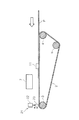
より詳しくは、図1及び図2に示すようにプリンタ1は記録用紙Pを搬送方向(図1及び図2の矢印方向:図1では上方向、図2では左方向)へ搬送する為の搬送面を形成する搬送ベルト2、およびこの搬送ベルト2を係回する複数のローラ(駆動ローラ3、従動ローラ4、5)を備えている。尚、符号6は駆動ローラ3を駆動する駆動モータを、符号20は駆動モータ6を制御するモータ駆動回路を、符号100はモータ駆動回路20をはじめプリンタ1の各種構成要素を制御する制御部を示している。
More specifically, as shown in FIGS. 1 and 2, the
搬送ベルト2は絶縁性ベルトであり、PETやポリイミド、フッ素系樹脂などの絶縁性樹脂で形成される。この搬送ベルト2は、図示を省略する帯電手段により帯電され、これにより搬送面上の記録用紙Pが搬送ベルト2に静電吸着されて、搬送方向へ確実に搬送される。
The
搬送ベルト2の搬送面と対向する位置にはインクを吐出する記録ヘッド7が設けられている。この記録ヘッド7には、例えばイエロー、マゼンダ、シアン、ブラックなどの各色のインクノズル(図示せず)が、記録用紙Pの搬送方向に色毎にずらして配設されている。各インクノズル(図示せず)には、各色用のインクタンク(図示せず)からインク供給チューブ(図示せず)を介してインクが供給される。
A
そして各インク吐出ノズルから必要量のインク滴が吐出されることにより、記録用紙P上に微小なインクドットが形成される。これを各色毎に行うことにより、搬送ベルト2に吸着された記録用紙Pを一度通過させるだけで、記録を完了させることができる。
Then, a small amount of ink dots are formed on the recording paper P by ejecting a necessary amount of ink droplets from each ink ejection nozzle. By performing this for each color, the recording can be completed by only passing the recording paper P adsorbed on the
搬送ベルト2の用紙搬送方向と直交する方向(用紙幅方向)の一方側の端部には、検出装置10を構成する被検出部12が搬送ベルト2と一体的に設けられている。被検出部12は、搬送ベルト2の搬送方向に沿って連続して途切れることなく設けられており、この被検出部12と対向する位置には検出装置10を構成する検出部11が設けられている。
A detected
被検出部12は、本実施形態では磁気記録層により構成されており、この磁気記録層は被検出要素としてのS極、N極の各磁極が、搬送方向に所定ピッチで交互に配置されて形成されている。検出部11は、本実施形態では接触式の磁気再生用ヘッドで構成されており、搬送ベルト2の駆動に伴う被検出部12の磁極の変化(S、N、S、N・・・)を検出し、その検出感度に応じた出力レベル(振幅)の波形信号を出力する。
In the present embodiment, the detected
搬送ベルト2において被検出部12が形成された側に対し反対側の側縁には、原点(タブ16)と、これを検出する原点検出部17とを備えて構成された原点検出装置15が設けられており、この原点検出装置15により、搬送ベルト2の所定位置、即ち原点が検出できるようになっている。
An
搬送ベルト2において被検出部12と対向する位置には、クリーニング部材23と電磁プランジャ22とを備えて構成されたクリーニング手段21が設けられている。クリーニング部材23は、被検出部12に当接して、被検出部12に付着したインクミスト、塵埃等の異物を除去(クリーニング)する。
A
クリーニング部材23は、不織布などの繊維材、スポンジなどの多孔質材、等のインク吸収性能及び耐インク性能に優れた材料により形成することが望ましい。しかしながらクリーニング部材23としては、被検出部12をクリーニング可能なものであればどのようなものであっても構わない。また、クリーニング部材23として、被検出部12をワイピングするワイパーなども採用することができる。
The cleaning
電磁プランジャ22は、制御部100からの指示により、クリーニング部材23を被検出部12に当接させるよう押し出し、或いはクリーニング部材23を被検出部12から離間させるよう引き込む。これにより被検出部12は、必要なタイミングでのみクリーニングされることとなる。従ってクリーニング部材23が常に被検出部12に当接し、記録実行中の搬送ベルト2へ搬送負荷を与え、記録品質の低下を招くことがない。
The
次に、図3を参照しながら制御部100の構成を説明する。制御部100は、主制御部101と、この主制御部101の制御下において記録ヘッド7を制御駆動するための印刷制御部109とが設けられている。主制御部101は、CPU102、メモリ103、クロック14、パルス発生部105、「判定部」としての汚れ判定部106、入力部107、出力部108、を備えている。
Next, the configuration of the
CPU102は、メモリ103に格納された動作プログラムを実行するものであり、主制御部101を構成する他の構成要素と信号やデータのやり取りを行いながら各種の処理を行う。メモリ103は上記動作プログラムを始め、各種の動作パラメータやCPU102の動作時に生じる各種の処理データを一時的に格納する。クロック104は、CPU102や汚れ判定部106に対して各種処理に必要なクロック信号Scを出力する。
The
入力部107には、原点検出装置15の検出部17からの原点検出信号や、プリンタ1に設けられたその他のセンサなどからの検出信号等が入力され、これら各種信号をCPU102に適した信号に変換して供給する。
The
パルス発生部105には、検出装置10の検出部11から、被検出部12の検出感度に応じた出力レベルの波形信号が入力され、これを処理して前記波形信号の周期に応じた汚れ検出用パルスPd及びインク吐出用パルスPsを生成する。そして汚れ検出用パルスPdは、汚れ判定部106へと出力され、インク吐出用パルスPsは、CPU102へと出力される。
The
汚れ判定部106はパルス発生部105からの汚れ検出用パルスPdの出力状態を判定し、汚れ検出用パルスPdが出力されている状態(出力状態)から出力されない状態(非出力状態)への遷移を検出(判定)すると、その旨を示す信号(以下「汚れ検出信号」と言う)SdをCPU102へ出力する。
The
印刷制御部109は、主制御部101のパルス発生部105で生成されるインク吐出用パルスPsに基づいて、記録ヘッド7を駆動する駆動信号Spを生成する。具体的には、駆動信号Spを、インク吐出用パルスPsのパルスのタイミングと同期した波形となるように整形し、記録ヘッド7がインク吐出用パルスPsと同期して動作するように、すなわち、搬送ベルト2の搬送方向に向けた所定の単位移動量に対応して一つのインク滴を吐出するように制御する。なお、この印刷制御部109には、主制御部101から上記インク吐出用パルスPsとともに画像データが送られ、この画像データが上記駆動信号Spに反映されることにより、記録ヘッド7のインク吐出態様(例えば、色や濃度など)が制御される。
The
次に、図4を参照しながらパルス発生部105及び汚れ判定部106について詳説する。図5(A)に示すように、パルス発生部105は増幅回路110と、「第1デジタル信号出力部」としての比較器112と、「第2デジタル信号出力部」としての比較器111と、を備えている。
Next, the
増幅回路110は、検出装置10の検出部11から出力された波形信号(以下「エンコーダ信号」とも言う)を増幅して比較器111、112へと送る。尚、エンコーダ信号は、例えば図5(A)に示すような波形となる。
The
比較器112はエンコーダ信号の出力レベル(出力電圧)を第1閾値(基準電圧)に基づき二値化して出力するヒステリシスコンパレータである。比較器112はエンコーダ信号の出力レベルがHigh側の第1閾値を超えると出力をHighとし、エンコーダ信号の出力レベルがLow側の第1閾値を下回ると出力をLowとし、例えば図5(C)に示すような、エンコーダ信号の波形周期に応じた「第1デジタル信号」としてのインク吐出用パルスPsを送出する。
The
比較器111はエンコーダ信号の出力レベル(出力電圧)を第1閾値より絶対値の高い第2閾値(基準電圧)に基づき二値化して出力するヒステリシスコンパレータである。比較器111はエンコーダ信号の出力レベルがHigh側の第2閾値を超えると出力をHighとし、エンコーダ信号の出力レベルがLow側の第2閾値を下回ると出力をLowとし、例えば図5(B)に示すような、エンコーダ信号の波形周期に応じた「第2デジタル信号」としての汚れ検出用パルスPdを送出する。
The
尚、図5(B)はエンコーダ信号の出力レベルがLow側の第2閾値を下回った後に(エンコーダ信号の(d)地点)、High側の第2閾値を超えなくなった例(エンコーダ信号の(e)地点)を示すものであり、従って図の実線のように矩形波信号出力停止後(立ち上がりエッジ及び立ち下がりエッジのいずれも生じない、即ち状態変化の停止後)の比較器111からの出力信号はLowとなる。しかし例えばエンコーダ信号の出力レベルがHigh側の第2閾値を超えた後に、Low側の第2閾値を下回らなくなった場合には、図の2点鎖線で示すように矩形波信号出力停止後の比較器111からの出力信号はHighとなる。
5B shows an example in which the output level of the encoder signal does not exceed the second threshold value on the high side after the output level of the encoder signal falls below the second threshold value on the low side (point (d) of the encoder signal). e) indicates a point), and therefore the output from the
尚、比較器111の閾値(基準電圧)は、抵抗R1とR2の比によって調整することができ、比較器112の閾値(基準電圧)は、抵抗R3とR4の比によって調整することができる。
続いて図4(B)に示すように、汚れ判定部106はアップダウンカウンタ113と、ラッチ回路114と、を備えている。
The threshold (reference voltage) of the
Subsequently, as illustrated in FIG. 4B, the
アップダウンカウンタ113は、汚れ検出用パルスPdの立ち下がりエッジにより、クロック信号Scに同期したカウントアップを開始し、汚れ検出用パルスPdの立ち上がりエッジを受信するまで前記カウントアップを継続する。また、汚れ検出用パルスPdの立ち上がりエッジにより、クロック信号Scに同期したカウントダウンを開始し、汚れ検出用パルスPdの立ち下がりエッジを受信するまで前記カウントダウンを継続する。 The up / down counter 113 starts counting up in synchronization with the clock signal Sc by the falling edge of the dirt detection pulse Pd, and continues the count up until the rising edge of the dirt detection pulse Pd is received. Further, the countdown in synchronization with the clock signal Sc is started by the rising edge of the dirt detection pulse Pd, and the countdown is continued until the falling edge of the dirt detection pulse Pd is received.
これによりカウント値は、立ち下がりエッジから立ち上がりエッジまでの時間(カウントアップの場合)、或いは立ち上がりエッジから立ち下がりエッジまでの時間(カウントダウンの場合)を示すものとなる。従って汚れ検出用パルスPdの立ち上がりエッジと立ち下がりエッジが規則的に発生していれば、カウント値は或る一定の範囲内(最大値と最小値の間)で動き、当該一定の範囲から外れることはない。 As a result, the count value indicates the time from the falling edge to the rising edge (when counting up) or the time from the rising edge to the falling edge (when counting down). Therefore, if the rising edge and the falling edge of the dirt detection pulse Pd are regularly generated, the count value moves within a certain range (between the maximum value and the minimum value) and deviates from the certain range. There is nothing.
アップダウンカウンタ113は、カウント値の最大値及び最小値を指定する為のデータSeの入力を受け付けるカウント値データ入力部を備えており、即ち前記最大値及び最小値を外部から指定可能となっている。そしてカウント値が指定された最大値を上回った場合、或いは最小値を下回った場合には、ラッチ回路114へラッチ信号Stを送出する。
The up / down
ラッチ回路114は、リセット信号Srを受信することによりその出力信号をLowとし、ラッチ信号Stを受信することにより、その出力信号をHighにラッチする。そしてCPU102は、ラッチ回路114の出力信号(汚れ検出信号Sd)がLowからHighに遷移すると、クリーニング手段21を制御して、被検出部12のクリーニングを実行する。
The
以下、図5及び図6を参照しながら更に説明する。エンコーダ信号の出力レベルが第1閾値及び第2閾値を超える場合には(図5(A)の(a)〜(d)地点)、汚れ検出用パルスPdとインク吐出用パルスPsがともに出力され、インク吐出用パルスPsの状態変化に同期して記録用紙Pへのインク吐出動作が実行される。 Hereinafter, further description will be given with reference to FIGS. 5 and 6. When the output level of the encoder signal exceeds the first threshold value and the second threshold value (points (a) to (d) in FIG. 5A), both the stain detection pulse Pd and the ink ejection pulse Ps are output. The ink ejection operation onto the recording paper P is executed in synchronization with the change in the state of the ink ejection pulse Ps.
次に被検出部12がインクミスト等により汚れ、被検出部12の検出感度が低下し始めると、まず最初にエンコーダ信号の出力レベルが第1閾値より高い第2閾値を下回り(図5(A)の(e)〜(h)地点)、これによって図5(B)に示すように、汚れ検出用パルスPdの状態変化が停止する。
Next, when the detected
この時点では、エンコーダ信号は一定以上の出力レベルを有しており、即ち第1閾値を超えりレベルであり、ほぼ正確な用紙搬送量を検出しているので、インク吐出用パルスPsは状態変化が継続する。 At this time, the encoder signal has an output level higher than a certain level, that is, exceeds the first threshold value, and has detected a substantially accurate paper conveyance amount, so that the ink ejection pulse Ps changes its state. Will continue.
一方、汚れ判定部106は、汚れ検出用パルスPdの立ち下がりエッジによりクロック信号Scに同期したカウントアップを開始し、次に立ち上がりエッジを受信するまでカウントアップを継続するよう構成されている。また、汚れ検出用パルスPdの立ち上がりエッジによりクロック信号Scに同期したカウントダウンを開始し、次に立ち下がりエッジを受信するまでカウントダウンを継続するよう構成されている。
On the other hand, the
従って例えば、汚れ検出用パルスPdの立ち下がりエッジによりカウントアップを開始したものの、図5(B)に示すように汚れ検出用パルスPdの状態変化が停止し、パルス発生部105(比較器111)からの出力がLowのまま所定時間経過すると、カウント値が指定された最大値を上回る。 Therefore, for example, although the count-up is started by the falling edge of the dirt detection pulse Pd, the state change of the dirt detection pulse Pd is stopped as shown in FIG. 5B, and the pulse generator 105 (comparator 111). When a predetermined time elapses while the output from is low, the count value exceeds the specified maximum value.
そしてこれによりラッチ信号Stがラッチ回路114へ出力され、汚れ検出信号Sdが図5(D)に示すようにHighにラッチされる。従ってCPU102は汚れ検出部106からの汚れ検出信号SdがLowからHighに切り換わることで被検出部12の汚れ発生と判断することができる。
As a result, the latch signal St is output to the
尚、汚れ判定部106が汚れ検出用パルスPdの立ち上がりエッジによりクロック信号Scに同期したカウントダウンを開始したものの、汚れ検出用パルスPdの出力が停止し、パルス発生部105(比較器111)からの出力がHighのまま所定時間経過すると(図5(B)の2点鎖線で示す例)、カウント値が指定された最小値を下回る。これにより同様にラッチ信号Stがラッチ回路114へ出力され、汚れ検出信号Sdが図5(D)に示すようにHighにラッチされるので、CPU102は被検出部12の汚れ発生と判断することができる。
Although the
以上のようにCPU102は汚れ検出部106からの汚れ検出信号SdがLowからHighに切り換わることで被検出部12の汚れ発生と判断することができる。しかしながら制御部100は、被検出部12の汚れと判断しても必ずしも直ちにクリーニング手段21を制御して被検出部12のクリーニングを実行するとは限らない。以下、これを図6を参照しながら説明する。
As described above, the
印刷ジョブの開始時には、先ず最初に汚れ検出フラグを”0”(汚れていない)にセットする(ステップS101)。次いで印刷を開始し(ステップS102)、その後は汚れ検出信号Sdの状態を監視する(ステップS103)。汚れ検出信号SdがLowからHighに切り換わると(ステップS103の肯定枝)、汚れ検出フラグを”1”(汚れている)にセットする(ステップS104)。 At the start of a print job, first, the stain detection flag is set to “0” (not dirty) (step S101). Next, printing is started (step S102), and thereafter the state of the stain detection signal Sd is monitored (step S103). When the dirt detection signal Sd switches from Low to High (Yes in step S103), the dirt detection flag is set to “1” (dirty) (step S104).
ここで、現在印刷ページへの印刷が終了しているか否かを判断し(ステップS105)、終了していなければ(否定枝)、終了するまで印刷を継続する。現在印刷ページの印刷が終了した場合には(肯定枝)、クリーニング実行回数を示す変数Nをゼロにセットし、クリーニング手段21を制御してクリーニング動作を実行し(ステップS107)、クリーニング実行回数を示す変数Nをインクリメントする(ステップS108)。
Here, it is determined whether or not printing on the current print page has been completed (step S105). If it has not been completed (negative branch), printing is continued until the printing is completed. When printing of the current print page is finished (Yes branch), the variable N indicating the number of cleaning executions is set to zero, the
クリーニング後、印刷を行わずに搬送ベルト2のみを駆動するダミー搬送動作を実行し(ステップS109)、汚れ検出信号Sdの状態、即ち被検出部12がクリーニングされた結果、エンコーダ信号の出力レベルが第2閾値を超えるまでに回復したか否かを判定する(ステップS110)。
After cleaning, a dummy transport operation is performed in which only the
クリーニング動作の結果、被検出部12の汚れを検出しなければ(ステップS110の否定枝)、汚れ検出フラグを”0”に戻し(ステップS111)、次ページの印刷がある場合には再度ステップS102へ戻る(ステップS112の肯定枝)。
As a result of the cleaning operation, if the contamination of the detected
一方、クリーニング動作の結果、なおも被検出部12が汚れていると判定された場合には(ステップS110の肯定枝)、クリーニング実行回数を示す変数Nが予め定められた最大回数α以下であるか否かを判断し(ステップS113)、最大回数αを超えていない場合には(肯定枝)、再度クリーニング動作を実行する。最大回数αを超えている場合には(ステップS113の否定枝)、被検出部12がクリーニング不可能な程汚れているか、或いはその他の異常が生じていると判断して、エラー表示を行う。
On the other hand, if it is determined that the detected
以上説明したように、制御部100は検出装置10の検出部11が出力するエンコーダ信号の出力レベルに対する閾値として2つの閾値(第1閾値とこれより高い第2閾値)を用い、第1閾値を被検出部12の検出結果(即ち用紙搬送量の検出結果)としての検出信号(インク吐出用パルスPs)の生成に用い、第2閾値を被検出部12の汚れ判定用信号(汚れ検出用パルスPd)の生成に用いる。
As described above, the
そして被検出部12の汚れと判断しても、所定条件の下、つまりエンコーダ信号が第1閾値を上回る限りは、引き続きインク吐出用パルスPsの状態変化が継続される。この為、被検出部12の汚れと判断しても、インク吐出用パルスPsを利用して印刷を継続することができ、これにより記録動作を途中で中断或いは中止せずに、記録実行中の記録用紙Pへの印刷動作を完了することができる。このため、記録用紙Pの無駄が生じないとともに、記録品質を低下させることもない。
Even if it is determined that the detected
尚、本実施形態ではパルス発生部105が出力する汚れ検出用パルスPdを汚れ判定部106に出力し、汚れ判定部106において汚れ検出用パルスPdの状態を判定しているが、パルス発生部105が出力する汚れ検出用パルスPdが直接CPU102へ入力するよう構成し、CPU102により汚れ検出用パルスPdの状態を判定しても構わない。
In the present embodiment, the dirt detection pulse Pd output from the
また本実施形態では、制御部100は、印刷実行中に被検出部12の汚れが発生したと判断しても、直ちに被検出部12のクリーニング動作を実行するのではなく、その際の印刷中のページについては印刷を完了し、その後にクリーニング動作を実行するので、途中で印刷を中断してその後再度印刷する場合のように記録品質を低下させることがない。
In this embodiment, even if the
更にクリーニング動作を1回実行する毎に、エンコーダ信号の出力レベルが第2閾値を超えるまでに回復したか否かを確認するので、予め定められた複数回のクリーニング動作を実行する場合のように過度のクリーニングを防止でき、装置のダウンタイムを短縮できるとともに、被検出部12の損耗を最小限に抑えることができる。
Further, each time the cleaning operation is performed once, it is checked whether or not the output level of the encoder signal has recovered until the second threshold value is exceeded, so that a plurality of predetermined cleaning operations are performed. Excessive cleaning can be prevented, downtime of the apparatus can be shortened, and wear of the detected
尚、本実施形態ではクリーニング手段21を備え、被検出部12の汚れが発生したと判断した場合にはクリーニング手段21を制御して被検出部12のクリーニングを実行するが、例えばクリーニング手段21を備えずに、或いは備えていても、被検出部12の汚れが発生した旨の警告表示を行い、ユーザに被検出部12のクリーニングを促すようにすることも可能である。
In this embodiment, the
また本実施形態では、アップダウンカウンタ113のカウント値の最大値と最小値、即ち、汚れ検出用パルスPdが出力されているか否かの判定(被検出部12が汚れているか否かの判定)を行う為の基準値が可変であるので、搬送ベルト2の駆動速度や速度変動(モータの回転むら)等に応じた適切な基準値で、上記判定を行うことができる。
In the present embodiment, the maximum and minimum count values of the up / down
例えば、搬送ベルト2の駆動速度は、記録用紙Pへ記録を行う際の記録モード(「きれい」、「はやい」、等)により変化するので、記録モードに応じて上記最大値と最小値を設定することが考えられる。
For example, since the driving speed of the
尚、上記実施形態においては、本発明に係る検出装置を搬送ベルト2の動作検出(用紙搬送量検出)に適用したが、これに限られるものではなく、例えば主走査方向に往復動するキャリッジを備えた記録装置において、キャリッジの動作検出(位置・速度の検出)に適用することも可能である。この場合、キャリッジの側(可動側)に検出部11を設け、装置本体側(固定側)に被検出部12を設けることとなる。
In the above embodiment, the detection device according to the present invention is applied to the detection of the movement of the conveyor belt 2 (paper conveyance amount detection). However, the present invention is not limited to this. For example, a carriage that reciprocates in the main scanning direction is used. The recording apparatus provided can also be applied to carriage motion detection (position / velocity detection). In this case, the
この様な形態においても、キャリッジの動作速度は記録モードにより異なる場合があるので、記録モードに応じて上記最大値及び最小値を設定する。また、キャリッジは定速区間の両側に加速区間と減速区間を有しているので、この区間で汚れ検出を行う場合には、キャリッジの位置に応じて、上記最大値及び最小値を切り換える。 Even in such a configuration, the carriage operating speed may vary depending on the recording mode, and therefore the maximum value and the minimum value are set according to the recording mode. Further, since the carriage has an acceleration section and a deceleration section on both sides of the constant speed section, when performing dirt detection in this section, the maximum value and the minimum value are switched according to the position of the carriage.
また本発明はその他にも種々の変形を行うことができ、即ちエンコーダ信号の出力レベルに対し第1閾値とこれより高い第2閾値を適用し、第2閾値を用いて被検出部の汚れを判定し、第1閾値を用いて動体の位置、速度等を検出するように構成されたものであれば、どのような構成であっても構わない。 In addition, the present invention can be modified in various other ways, that is, the first threshold value and the second threshold value higher than the first threshold value are applied to the output level of the encoder signal, and the detected portion is stained using the second threshold value. Any configuration may be used as long as it is configured to detect and detect the position, speed, etc. of the moving object using the first threshold.
1 インクジェットプリンタ、2 搬送ベルト、3 駆動ローラ、4、5 従動ローラ、6 駆動モータ、7 記録ヘッド、10 検出装置、11 検出部、12 被検出部、15 原点検出装置、16 原点(タブ)、17 原点検出部、20 モータ駆動回路、21 クリーニング手段、22 電磁プランジャ、23 クリーニング部材、100 制御部、101 主制御部、102 CPU、103 メモリ、104 クロック、105 パルス発生部、106 汚れ判定部、107 入力部、108 出力部、109 印刷制御部、110 増幅回路、111、112 比較器、113 アップダウンカウンタ、114 ラッチ回路、P 記録用紙
DESCRIPTION OF
Claims (3)
前記搬送ベルトに設けられ、被記録媒体の搬送方向に沿って被検出要素が配列されて成る被検出部と、
前記搬送ベルトの移動に伴い前記被検出要素を検出し、その検出レベルに応じた波形信号を出力する検出部と、
前記波形信号を第1閾値に基づき二値化して第1デジタル信号を出力する第1デジタル信号出力部と、
前記第1デジタル信号に基づき被記録媒体への記録動作を実行する記録手段と、
前記波形信号を前記第1閾値より絶対値の高い第2閾値に基づき二値化して第2デジタル信号を出力する第2デジタル信号出力部と、
前記第2デジタル信号に状態変化が生じているか否かを判定する判定部と、
を備え、
前記記録手段は、前記判定部により前記第2デジタル信号に状態変化が生じていないと判定され、前記第1デジタル信号に状態変化が生じていると判定された状態では、実行中の被記録媒体への記録を継続することを特徴とする記録装置。 A transport belt that forms a transport surface that moves in the transport direction of the recording medium;
A detected portion provided on the conveyor belt, in which detected elements are arranged along the conveying direction of the recording medium;
Detecting the detected element as the conveyor belt moves, and outputting a waveform signal corresponding to the detection level;
A first digital signal output unit that binarizes the waveform signal based on a first threshold and outputs a first digital signal;
Recording means for performing a recording operation on a recording medium based on the first digital signal;
A second digital signal output unit that binarizes the waveform signal based on a second threshold having an absolute value higher than the first threshold and outputs a second digital signal;
A determination unit for determining whether or not a state change occurs in the second digital signal;
Equipped with a,
The recording means determines that no state change has occurred in the second digital signal by the determination unit, and in a state in which it has been determined that a state change has occurred in the first digital signal, the recording medium being executed A recording apparatus characterized in that recording is continued .
前記クリーニング手段を制御する制御部が、前記判定部により前記第2デジタル信号に状態変化が生じていないと判定されると、実行中の被記録媒体への記録を完了した後に、前記クリーニング手段を制御して前記被検出部のクリーニングを実行する、
ことを特徴とする記録装置。 The recording apparatus according to claim 1 , further comprising a cleaning unit that cleans the detected portion.
When the control unit that controls the cleaning unit determines that the second digital signal has not changed in state by the determination unit, after the recording on the recording medium being executed is completed, the cleaning unit Control to perform cleaning of the detected part;
A recording apparatus.
前記第2デジタル信号の立ち上がりエッジによりクロックに同期したカウントダウンを開始し、及び立ち下がりエッジによりクロックに同期したカウントアップを開始し、或いは、立ち上がりエッジによりクロックに同期したカウントアップを開始し、及び立ち下がりエッジによりクロックに同期したカウントダウンを開始し、カウント値が最大値を上回った場合、及びカウント値が最小値を下回った場合に、前記ラッチ回路へラッチ信号を出力するアップダウンカウンタと、
前記カウント値の最大値及び最小値を指定する為のデータの入力を受け付けるカウント値データ入力部と、
を備えたことを特徴とする記録装置。 The recording apparatus according to claim 1 , wherein the determination unit receives a latch signal and latches an output signal to High or Low;
The countdown synchronized with the clock is started by the rising edge of the second digital signal and the countup synchronized with the clock is started by the falling edge, or the countup synchronized with the clock is started by the rising edge and An up / down counter that starts a countdown synchronized with the clock by a falling edge, and outputs a latch signal to the latch circuit when the count value exceeds the maximum value and when the count value falls below the minimum value;
A count value data input unit for receiving input of data for designating the maximum value and the minimum value of the count value;
A recording apparatus comprising:
Priority Applications (2)
| Application Number | Priority Date | Filing Date | Title |
|---|---|---|---|
| JP2007268355A JP5040576B2 (en) | 2007-10-15 | 2007-10-15 | Detection device and recording device |
| US12/250,813 US8111409B2 (en) | 2007-10-15 | 2008-10-14 | Detecting apparatus and recording unit |
Applications Claiming Priority (1)
| Application Number | Priority Date | Filing Date | Title |
|---|---|---|---|
| JP2007268355A JP5040576B2 (en) | 2007-10-15 | 2007-10-15 | Detection device and recording device |
Publications (3)
| Publication Number | Publication Date |
|---|---|
| JP2009096022A JP2009096022A (en) | 2009-05-07 |
| JP2009096022A5 JP2009096022A5 (en) | 2010-11-11 |
| JP5040576B2 true JP5040576B2 (en) | 2012-10-03 |
Family
ID=40533911
Family Applications (1)
| Application Number | Title | Priority Date | Filing Date |
|---|---|---|---|
| JP2007268355A Expired - Fee Related JP5040576B2 (en) | 2007-10-15 | 2007-10-15 | Detection device and recording device |
Country Status (2)
| Country | Link |
|---|---|
| US (1) | US8111409B2 (en) |
| JP (1) | JP5040576B2 (en) |
Families Citing this family (5)
| Publication number | Priority date | Publication date | Assignee | Title |
|---|---|---|---|---|
| ITMI20061227A1 (en) * | 2006-06-26 | 2007-12-27 | Dante Frati | PROCEDURE FOR PRINTING SURFACES OF FLAT BASE ELEMENTS |
| JP2014185010A (en) * | 2013-03-25 | 2014-10-02 | Seiko Epson Corp | Liquid ejection device |
| JP6288436B2 (en) * | 2014-03-20 | 2018-03-07 | セイコーエプソン株式会社 | Recording apparatus and recording medium conveying method |
| JP6540274B2 (en) * | 2015-06-29 | 2019-07-10 | セイコーエプソン株式会社 | Printing device |
| US10386754B2 (en) * | 2016-02-19 | 2019-08-20 | Ricoh Company, Ltd. | Belt device and image forming apparatus incorporating same |
Family Cites Families (15)
| Publication number | Priority date | Publication date | Assignee | Title |
|---|---|---|---|---|
| JPH11344361A (en) * | 1998-06-03 | 1999-12-14 | Olympus Optical Co Ltd | Optical encoder |
| JP2001121721A (en) | 1999-10-25 | 2001-05-08 | Canon Inc | Recording device |
| JP4374119B2 (en) * | 2000-06-28 | 2009-12-02 | 株式会社 ソキア・トプコン | Absolute encoder |
| JP2002254743A (en) | 2001-03-05 | 2002-09-11 | Canon Inc | Position encoder, position control device using it, image recording device and electronic equipment, and controlling method for them |
| JP2003145877A (en) | 2001-11-16 | 2003-05-21 | Copyer Co Ltd | Serial printer |
| JP2003175650A (en) | 2001-12-12 | 2003-06-24 | Canon Inc | Imaging apparatus |
| JP2005238706A (en) | 2004-02-27 | 2005-09-08 | Fuji Xerox Co Ltd | Imaging device |
| JP2006056079A (en) | 2004-08-18 | 2006-03-02 | Ricoh Co Ltd | Image forming apparatus |
| JP2006213042A (en) | 2005-01-04 | 2006-08-17 | Ricoh Co Ltd | Image formation device |
| JP2006347039A (en) * | 2005-06-17 | 2006-12-28 | Seiko Epson Corp | Inkjet printer and apparatus for controlling it |
| US7652609B2 (en) * | 2005-08-01 | 2010-01-26 | Samsung Electronics Co., Ltd. | Apparatus and method for detecting motion with low power consumption in inertia sensor |
| JP2007160715A (en) | 2005-12-14 | 2007-06-28 | Seiko Epson Corp | Liquid ejecting apparatus |
| JP2007155443A (en) | 2005-12-02 | 2007-06-21 | Denso Corp | Sensor signal processor |
| JP2008107447A (en) * | 2006-10-24 | 2008-05-08 | Kyocera Mita Corp | Image forming apparatus |
| US20100013989A1 (en) * | 2008-07-18 | 2010-01-21 | Samsung Electronics Co. Ltd. | Method and system for controlling fallback in generating intermediate fields of a video signal |
-
2007
- 2007-10-15 JP JP2007268355A patent/JP5040576B2/en not_active Expired - Fee Related
-
2008
- 2008-10-14 US US12/250,813 patent/US8111409B2/en not_active Expired - Fee Related
Also Published As
| Publication number | Publication date |
|---|---|
| US20090097081A1 (en) | 2009-04-16 |
| JP2009096022A (en) | 2009-05-07 |
| US8111409B2 (en) | 2012-02-07 |
Similar Documents
| Publication | Publication Date | Title |
|---|---|---|
| EP2089235B1 (en) | Image forming appratus, image forming system, image forming method, control program for eliminating conveyance failure, and information recording medium having recorded thereon control program for eliminating conveyance failure | |
| US7789475B2 (en) | Image forming apparatus | |
| JP2009249166A (en) | Pulse signal generating device, transport device, image forming apparatus and pulse generating method | |
| JP5040576B2 (en) | Detection device and recording device | |
| US9022500B2 (en) | System and method for adjusting the registration of an image applied to recording media in a printing system | |
| JP2010058503A (en) | Inkjet recording apparatus, and inkjet recording method | |
| JP2009248502A (en) | Pulse signal generating device, transport device, image forming apparatus, and pulse generating method | |
| JP2006213042A (en) | Image formation device | |
| US8300242B2 (en) | Image forming apparatus and pulse generating method | |
| JP2010284924A (en) | Image forming apparatus and image forming program | |
| JP2011168028A (en) | Image forming apparatus | |
| JP2009208457A (en) | Image forming device | |
| JP6606954B2 (en) | Recording device | |
| JP2006240251A (en) | Liquid droplet discharge type recorder | |
| JP5720136B2 (en) | Image forming apparatus and program | |
| JP2008179103A (en) | Image forming apparatus | |
| JP2005246858A (en) | Image forming apparatus | |
| JP5402432B2 (en) | Image forming apparatus and program | |
| JP2006056623A (en) | Image forming device | |
| US11358404B2 (en) | Printer and method for preventing erroneous interruption of printing | |
| JP2005246733A (en) | Image forming apparatus | |
| JP6736863B2 (en) | Liquid ejector | |
| JP2005096228A (en) | Inkjet recording apparatus | |
| JP2006347028A (en) | Method for adjusting liquid attaining position, liquid detecting apparatus, liquid delivering apparatus and program | |
| JP5353344B2 (en) | Image forming apparatus and program |
Legal Events
| Date | Code | Title | Description |
|---|---|---|---|
| RD03 | Notification of appointment of power of attorney |
Free format text: JAPANESE INTERMEDIATE CODE: A7423 Effective date: 20100917 |
|
| RD04 | Notification of resignation of power of attorney |
Free format text: JAPANESE INTERMEDIATE CODE: A7424 Effective date: 20100917 |
|
| A521 | Request for written amendment filed |
Free format text: JAPANESE INTERMEDIATE CODE: A523 Effective date: 20100924 |
|
| A621 | Written request for application examination |
Free format text: JAPANESE INTERMEDIATE CODE: A621 Effective date: 20100924 |
|
| A131 | Notification of reasons for refusal |
Free format text: JAPANESE INTERMEDIATE CODE: A131 Effective date: 20120228 |
|
| A977 | Report on retrieval |
Free format text: JAPANESE INTERMEDIATE CODE: A971007 Effective date: 20120229 |
|
| A521 | Request for written amendment filed |
Free format text: JAPANESE INTERMEDIATE CODE: A523 Effective date: 20120426 |
|
| TRDD | Decision of grant or rejection written | ||
| A01 | Written decision to grant a patent or to grant a registration (utility model) |
Free format text: JAPANESE INTERMEDIATE CODE: A01 Effective date: 20120612 |
|
| A01 | Written decision to grant a patent or to grant a registration (utility model) |
Free format text: JAPANESE INTERMEDIATE CODE: A01 |
|
| A61 | First payment of annual fees (during grant procedure) |
Free format text: JAPANESE INTERMEDIATE CODE: A61 Effective date: 20120625 |
|
| R150 | Certificate of patent or registration of utility model |
Ref document number: 5040576 Country of ref document: JP Free format text: JAPANESE INTERMEDIATE CODE: R150 Free format text: JAPANESE INTERMEDIATE CODE: R150 |
|
| FPAY | Renewal fee payment (event date is renewal date of database) |
Free format text: PAYMENT UNTIL: 20150720 Year of fee payment: 3 |
|
| S531 | Written request for registration of change of domicile |
Free format text: JAPANESE INTERMEDIATE CODE: R313531 |
|
| R350 | Written notification of registration of transfer |
Free format text: JAPANESE INTERMEDIATE CODE: R350 |
|
| LAPS | Cancellation because of no payment of annual fees |