JP5038569B2 - Strip casting - Google Patents
Strip casting Download PDFInfo
- Publication number
- JP5038569B2 JP5038569B2 JP2001524754A JP2001524754A JP5038569B2 JP 5038569 B2 JP5038569 B2 JP 5038569B2 JP 2001524754 A JP2001524754 A JP 2001524754A JP 2001524754 A JP2001524754 A JP 2001524754A JP 5038569 B2 JP5038569 B2 JP 5038569B2
- Authority
- JP
- Japan
- Prior art keywords
- roll
- casting
- gap
- rolls
- strip
- Prior art date
- Legal status (The legal status is an assumption and is not a legal conclusion. Google has not performed a legal analysis and makes no representation as to the accuracy of the status listed.)
- Expired - Fee Related
Links
Images


Classifications
-
- B—PERFORMING OPERATIONS; TRANSPORTING
- B22—CASTING; POWDER METALLURGY
- B22D—CASTING OF METALS; CASTING OF OTHER SUBSTANCES BY THE SAME PROCESSES OR DEVICES
- B22D11/00—Continuous casting of metals, i.e. casting in indefinite lengths
- B22D11/06—Continuous casting of metals, i.e. casting in indefinite lengths into moulds with travelling walls, e.g. with rolls, plates, belts, caterpillars
- B22D11/0622—Continuous casting of metals, i.e. casting in indefinite lengths into moulds with travelling walls, e.g. with rolls, plates, belts, caterpillars formed by two casting wheels
-
- B—PERFORMING OPERATIONS; TRANSPORTING
- B22—CASTING; POWDER METALLURGY
- B22D—CASTING OF METALS; CASTING OF OTHER SUBSTANCES BY THE SAME PROCESSES OR DEVICES
- B22D11/00—Continuous casting of metals, i.e. casting in indefinite lengths
- B22D11/06—Continuous casting of metals, i.e. casting in indefinite lengths into moulds with travelling walls, e.g. with rolls, plates, belts, caterpillars
- B22D11/0637—Accessories therefor
- B22D11/068—Accessories therefor for cooling the cast product during its passage through the mould surfaces
- B22D11/0682—Accessories therefor for cooling the cast product during its passage through the mould surfaces by cooling the casting wheel
-
- B—PERFORMING OPERATIONS; TRANSPORTING
- B22—CASTING; POWDER METALLURGY
- B22D—CASTING OF METALS; CASTING OF OTHER SUBSTANCES BY THE SAME PROCESSES OR DEVICES
- B22D11/00—Continuous casting of metals, i.e. casting in indefinite lengths
- B22D11/16—Controlling or regulating processes or operations
Description
【0001】
【発明の属する技術分野】
本発明は、双ロール鋳造装置での連続鋳造による金属ストリップ鋳造に関する。
【0002】
【従来の技術】
双ロール鋳造装置では、相互方向に回転する一対の冷却された水平鋳造ロール間に溶融金属を導き、動いているロール表面上で金属殻を凝固させ、ロール間隙にてそれら金属殻を合体させ、ロール間のロール間隙から下方に送給される凝固ストリップ品を生み出す。本明細書では、「ロール間隙」(nip)という語をロール同士が最接近する領域全般を指すものとして用いる。溶融金属は取鍋から1つ又は一連の小容器へと注がれ、更にはそこからロール間隙上方に位置した金属供給ノズルに流れてロール間のロール間隙へと向かい、その結果、ロール間隙直上のロール鋳造表面に支持されてロール間隙長さ方向に延びる溶融金属の鋳造溜めを形成する。通常、この鋳造溜めの端は、ロール端面に摺動係合で保持されて鋳造溜めの両端からの溢流を防ぐ側部板又は側部堰で構成されるが、電磁バリヤ等の代替手段も提案されている。
【0003】
双ロール鋳造装置での鋳造開始には重大な諸問題があり、特に鋼ストリップの鋳造の場合にそうである。立上げ時にロールに支持された鋳造溜めを確立する必要がある。定常状態鋳造が確立されればロール間のロール間隙は凝固したストリップで閉じられるが、立上げ時には溶融金属が適切に凝固することなく落下し得、従って、首尾一貫したストリップを製造するのが不可能となる。ロール間の隙間を閉止しつつ鋳造溜めを確立するために立上げ時にはダミーバーを鋳造ロール間に導入し、凝固ストリップが形成されたら、その先端でダミーバーを抜き去る必要があると以前は考えられていた。ダミーバー導入の必要があるため、鋳造に先立つ初期設定手順が遅延し、又何かの理由で鋳造を中断したら、この手順を繰返して鋳造を再開する必要があった。これが特に問題なのは鋼鋳造の場合で、鋼鋳造では溶融金属が非常に高温であり、金属送給システムの耐火材料を高温に予熱して鋳造直前に組付けねばならず、耐火材が著しく冷却し得る前の非常に短い時間内で溶融金属を注ぐ必要がある。双ロール鋳造装置での鋳造を開始する立上げ手順をダミーバーを用いることなく行えれば、鋳造中断後、鋳造装置を広範に再設定する必要なしに直ちに鋳造再開できる。
【0004】
【発明が解決しようとする課題】
特開昭59−215257及び特開平1−133644は、いずれも、ダミーバーを用いることなく双ロール鋳造装置での鋳造を立上げることができる案を開示している。これらの案ではいずれも、立上げ時に隙間変動と相応のロール速度制御とを強制する必要があるが、それらの狙いは単に、ロール間隙を塞止して鋳造溜めを確立するためロール間隙で隙間と凝固鋼殻の厚みとを整合させることである。特開昭59−215257で開示の案では、小さなロール間隙で立上げが始まり、比較的高ロール速度で鋳造を開始して所要のものより肉薄のストリップを造る。次いで、ロール間隙の規則的な増加を強制し、強制したロール間隙変動にストリップ厚増加を合わせるようロール速度を減速する。特開平1−133644で開示の案では、比較的幅広のロール間隙で立上げを開始し、流れがロール全体に行き渡るようにし、次いでロール間隙を狭めて鋳造溜めが確立するようにし、その後でロール間隙を増加させて所要厚のストリップを製造する。強制したロール間隙を、凝固する金属の実際厚に合わせることは並外れて難しい。さらに又、これらの案では、立上げ時にロール表面がほぼ平行で間隙が均一であることを前提としている。しかしながら、肉薄の鋼ストリップを鋳造する場合、機械仕上げしたクラウンを付したロールを用いる必要のあることが判明している。より明細には、平らなストリップを製造するためには、ロールを負のクラウンに機械仕上げしなければならず、即ち、各ロール周面の、端部より中央部の径を小さくすることにより、鋳造時にロールが熱膨張を受けてほぼ平らとなって平らなストリップを製造するようにする必要がある。強制する間隙制御を含む先の案では、クラウンを付けたロールで立上げを成功させることが一般にできない。本発明は、鋳造立上げ時にロール間のロール間隙を強制することがないが、立上げ時に鋳造される金属厚に即応する、改良された方法を提供する。本発明によれば、クラウン付きのロールを使用することができ、又、金属凝固状態及び鋳造溜めの充填速度を最適化するための鋳造速度制御に大きな柔軟性を持たせることができる。
【0005】
【課題を解決するための手段】
本発明によれば、一対の第1及び第2冷却鋳造ロールを平行な関係に組立て、第1ロールを第2のロールに対し横方向に移動可能にして両者間にロール間隙を形成するようにし、ダミーバーなしで溶融金属を注いでロール間隙上方で第1及び第2鋳造ロール周面上に支持された溶融金属の鋳造溜めを形成し、ロール間隙から下方に送給される鋳造溜め内の溶融金属からストリップを鋳造することからなり、鋳造手始めの鋳造溜めが形成される前に、第2鋳造ロールを横方向に移動しないよう保持し、止め手段を位置決めして第2鋳造ロールに向かう第1鋳造ロールの横方向移動を制限することにより、第1及び第2鋳造ロール間のロール間隙で初期間隙を設定し、前記初期間隙が連続鋳造すべきストリップの所望厚より小さく、鋳造溜めの形成後にストリップを所望厚に鋳造するために前記間隙が増加される金属ストリップ鋳造方法において、
鋳造手始めに、前記第1鋳造ロールを第2鋳造ロールの方へと横方向に連続偏寄させ、第1及び第2鋳造ロールを、金属殻が両鋳造ロール周面で凝固してロール間隙に向かって移動するような速度で相互方向に回転させることにより、第1及び第2鋳造ロール間で設定された初期間隙より大きな厚みのストリップを鋳造手始めに直ちに製造し、
第1鋳造ロールが連続偏寄に抗して第2鋳造ロールから横方向に離れることを許容し、ロール間のロール間隙で間隙を増加させ、それにより、初期鋳造ストリップ厚に順応させ、ストリップを前記所望厚に連続鋳造可能にする
ことを特徴とする金属ストリップ鋳造方法が提供される。
【0006】
好ましくは、ロール中央部をロール端部周面の径よりも小さな径で形成することにより、第1及び第2鋳造ロール周面が半径方向に負のクラウンを備え、鋳造ロール周面端部間が0.5〜1.4mmの範囲の間隔を持つよう初期間隙を設定する。
【0008】
好ましくは、ロール表面の中央部と前記端部との径の差である、各ロールの半径方向負のクラウンを0.1〜1.5mmの範囲とすることができる。
【0011】
偏寄力は、偏寄ばねにより可動ロール台車に加えることができる。
【0012】
【発明の実施の形態】
本発明を更に充分に説明できるよう、添付図面を参照して1つの特定の形の鋳造装置の作動を幾分詳細に記述する。
【0013】
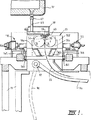
図示した鋳造装置は、工場床(図示せず)から起立し、鋳造ロールモジュールを支持した主機械フレーム11で構成される。鋳造ロールモジュールは、鋳造装置内の作動位置に導入して一体にでき、しかも、鋳造ロール交換時には容易に取外せるカセット13の形をしている。カセット13が担持する一対の平行な鋳造ロール16には溶融金属が、鋳造作業時に取鍋(図示せず)からタンディッシュ17、分配器18、供給ノズル19を介し供給されて鋳造溜め30を創る。鋳造ロール16は水冷なので、動いているロール表面上に殻が凝固し、それらがロール間隙にて合わされ、ロール出口で凝固ストリップ品20を造る。この品は標準コイラに送ることができる。
【0014】
鋳造ロール16は、電動モータの駆動軸41と主機械フレームに取付られたトランスミッションとを介し相互方向に回転される。駆動軸は、カセットを取出すべきときには、トランスミッションから切離しできる。ロール16の銅製周壁に形成され縦方向に延び周方向に離間した一連の水冷通路には、回転グランド43を介して給水ホース42に接続されたロール駆動軸41内の給水導管からロール端を介し冷却水が供給される。ロールの典型的な大きさは径が約500mm、長さが最大2000mmで、ほぼその幅のストリップ品を造ることができる。
【0015】
取鍋は全く従来の構成であって、回転タレット上に支持され、そこからタンディッシュ17上方の位置へと運ばれ、タンディッシュ17を満たすことができる。タンディッシュにはスライドゲート弁47を装着し、サーボシリンダで動かすことにより、溶融金属をタンディッシュ17から弁47と耐火シュラウド48とを介し分配器18へ流すことができる。
【0016】
分配器18も従来構成のものであり、酸化マグネシウム(MgO)等の耐火材料で造られ広皿状に形成される。分配器18の一側はタンディッシュ17からの溶融金属を受け、分配器18他側には縦方向に離間した一連の金属出口開口52が備えられる。分配器18下部を担持する取付ブラケット53は、カセットを作動位置へ据付ける際、分配器を主機械フレーム11に取付けるためのものである。
【0017】
供給ノズル19はアルミナグラファイト等の耐火材料で造られた細長体として形成される。下部は内方下方にすぼまるようテーパ状になっていて鋳造ロール16間のロール間隙へと突入でき、上部には外方に突出する側部フランジ55が形成されて、主機械フレーム11の一部をなす取付ブラケット60上に位置する。
【0018】
ノズル19は一連の、水平方向に離間してほぼ上下に延びる流路を有し、金属を鋳造ロール16の幅方向全体にわたり適宜に低速排出し、初期凝固の生じるロール表面に直接衝突することなく溶融金属をロール間隙へと送給する。又は、ノズルには単一の連続長孔出口を設けて溶融金属の低速カーテン流を直接ロール間隙に送給したり、それを溶融金属鋳造溜めに浸漬させてもよい。
【0019】
溜めをロール両端で囲込むのが一対の側部閉止板56であり、ロールの段付き端57に当接保持される。側部閉止板56は窒化硼素等の強耐火材料で造られ、ロールの段付き端の湾曲に合ったスカロップ側端を有する。側部閉止板を中に取付できる板ホルダ82は一対の流体圧シリンダ装置83の作動により可動であり、鋳造ロールの段付き端に側部閉止板を係合させ、鋳造作業時に鋳造ロール上に形成される溶融金属鋳造溜めの端部閉止部を形成する。
【0020】
鋳造作業では、スライドゲート弁47を作動させて溶融金属をタンディッシュ17から分配器18へと注ぎ、金属供給ノズル19を介し鋳造ロール上に流下させることができる。ストリップ品20の頭端をエプロンテーブル96の作動によりピンチロールへとガイドし、更に巻取りステーション(図示せず)へとガイドする。エプロンテーブル96は主フレーム上のピボット取付具97から吊下がり、きれいな頭端が形成された後に流体圧シリンダ装置(図示せず)の作動によりピンチロールの方へと旋回できる。
【0021】
取外し可能なロールカセット13は、鋳造装置内の所定位置への据付け前に、鋳造ロール16をセットしてロール間隙を調節できる構成になっている。又、カセット据付け時に、主機械フレーム11上に取付けられている2対のロール偏寄装置110,111をカセットのロール支持部に迅速に接続して、ロールの分離に抗する偏寄力を提供することができる。
【0022】
ロールカセット13を構成する大きなフレーム102は、ロール16と、ロール間隙下方で鋳造ストリップを囲む耐火閉止部の上部103とを担持する。ロール16が取付けられるロール支持部104はロール端軸受(図示せず)を担持し、それら軸受によりロールは互いに平行な関係で縦軸線まわりに回転可能に取付けられる。2対のロール支持部104は線形軸受106によりカセットフレーム102に取付けられるのでカセットフレームの横方向に摺動でき、ロール全体の相互への接近・離反動を提供でき、従って、それら2本の平行ロール間の分離・閉止動が可能となる。
【0023】
ロールカセットフレーム102は2つの調節可能なスペーサ107も担持し、スペーサはロール下方、ロール間の中央垂直平面付近、二対のロール支持部104間に位置していて、2つのロール支持部の内方動を制限する止めとして働き、ロール間のロール間隙の最小幅を限定する。以下に説明するように、ロール偏寄装置110,111は、これら中央止めに対しロール支持部を内方へ移動させるよう作動可能であるが、プリセットの偏寄力に抗してロールの一方は外方へとばね運動することができる。
【0024】
各中央スペーサ107はウォーム又はねじ駆動ジャッキの形であり、鋳造装置の中央垂直平面に対し固定された本体108と、ジャッキ作動時に相等しく相反方向に動かし得る2端109とを有することにより、ジャッキを伸縮させて、鋳造装置中央垂直平面からロールを等間隔に維持しつつロール間隙の幅を調節できるようになっている。
【0025】
鋳造装置は、各対が各ロール16の支持部104に接続された二対のロール偏寄装置110,111を備えている。機械一側のロール偏寄装置110にはつる巻偏寄ばね112が嵌着されて、対応するロール支持部104に偏寄力を提供し、他方、機械他側の偏寄装置111は流体圧アクチュエータ113を組み入れている。偏寄装置110,111の詳細な構成を図8及び図9に示す。2つの別々な作動モードを提供する構成になっている。第1のモードでは、偏寄装置111がロックされて一方のロールの相応するロール支持部104を中央止め107に対し堅く保持し、他方のロールは装置110の偏寄ばね112の作用に抗して横方向に移動自在である。他方の作動モードでは、偏寄装置110がロックされて他方のロールの相応するロール支持部104を中央止めに対して堅く保持し、偏寄装置111の流体圧アクチュエータ113は相応するロールの、サーボ制御した流体圧偏寄を提供する。通常の鋳造では、単純ばね偏寄又はサーボ制御した偏寄を用いることが可能である。
【0026】
ロール偏寄装置110の詳細な構成を図8に示す。その図に示されているように、偏寄装置を構成するばね胴ハウジング114が外ハウジング115内に配され、外ハウジングは主機械フレーム116に固定ボルト117で固定される。
【0027】
ばねハウジング114には、外ハウジング115内を走行するピストン118が形成される。ばねハウジング114は、ピストン118に流体圧流体流を給排することにより、図8に示したような伸び位置と、縮み位置とに択一的に設定できる。ばねハウジング114外端が担持するねじジャッキ119は、歯車付きモータ120の操作により作動して、ねじジャッキにロッド130で接続されたばね応力プランジャ121の位置を設定できる。
【0028】
ばね112内端が作用するスラストロッド構造122は、ロードセル125を介して相応のロール支持部104に接続される。スラスト構造122は最初は引かれてコネクタ124によりロール支持部104と強固に係合する。偏寄装置を外すべき時には、コネクタ124は流体圧シリンダ123の作動により伸長可能である。
【0029】
図8に示すようにばねハウジング114を伸長させた状態で偏寄装置110をそれの相応ロール支持部104に接続した場合、ばねハウジングとねじジャッキの位置は機械フレームに対して固定であり、ばね応力プランジャ121の位置を設定することにより、ばね112の圧縮を調整し、固定した当接部として働かせることができ、それに対しばねが反応して、推力をスラスト構造122に、そして相応のロール支持部104に直接に加えることができる。この構成では、鋳造作業時の相対動は偏寄ばねに対するロール支持部104とスラスタ構造122の一体的な動きのみである。従って、ばねとロードセルが受けるのは単一源の摩擦荷重のみであり、ロール支持部に実際に加えられる荷重はロードセルにより非常に正確に測定できる。更に又、偏寄装置が作用してロール支持部104を内方へ止めに対し偏寄させるので、金属が実際に鋳造ロール間を通る前に所要のばね偏寄力をロール支持部に予荷重するよう調節でき、その偏寄力は後の鋳造作業時に維持される。
【0030】
偏寄装置111の詳細な構成を図9に示す。その図に示されているように、流体圧アクチュエータ113が、固定スタッド132により機械フレームに固定された外ハウジング構造131と、ロードセル137を介し相応のロール支持部114に作用するスラスタ構造134の一部をなす内側ピストン構造133とにより形成される。スラスタ構造は最初は引かれてコネクタ135によりロール支持部と強固に係合する。スラスタ構造をロール支持部から外すべき時には、コネクタは流体圧ピストンシリンダ装置136の作動により伸長可能である。流体圧アクチュエータ113を作動させてスラスタ構造134を、伸長状態と引込み状態との間を動かすことができ、伸長状態では推力を加え、推力はロードセル137を介し直接にロール支持部軸受104へと伝えられる。ばね偏寄装置110の場合と同様、鋳造時に生じる動きはロール支持部とスラスタ構造が一体となっての、偏寄装置の残りの部分に対する動きのみである。従って、流体圧アクチュエータとロードセルは単一源の摩擦荷重に対し作用するのみでよく、装置により加えられる偏寄力は非常に正確に制御・測定できる。ばね込め偏寄装置の場合と同様に、固定した止めに対しロール支持部が直接に内方へ偏寄するので、鋳造開始前に、正確に測定した偏寄力でロール支持部を予荷重することができる。
【0031】
通常の鋳造では、単に高圧流体をアクチュエータ113に加えることにより、偏寄装置111をロックして相応のロール支持部を中央止めに対して堅く保持し、偏寄装置110のばね112がロールの一方に必要な偏寄力を提供できる。又は、偏寄装置111をサーボ制御した偏寄力を提供するのに用いるのならば、ばね応力プランジャ121の位置を調節することにより装置110をロックして、ばね力を通常の鋳造に必要なロール偏寄力をはるかに超したレベルにまで増加させることで、ばねは相応のロール台車を中央止めに対し通常の鋳造時には堅く保持するが、過剰のロール分離力が生ずればロールを緊急解放する。
【0032】
ロールカセットフレーム102は4つのホイール141上に支持され、それにより鋳造装置内の作動位置に出入りできる。作動位置に到達したら、流体圧シリンダ装置144で構成した巻上げ機143の操作によりフレーム全体が持上げられ、機械中央に位置決めされる。
【0033】
本発明によれば、立上げ時のロール間のロール間隙が鋳造すべきストリップ厚よりもはるかに小であるように中央スペーサ又は止め107が鋳造作業前にセットされる。肉薄の鋼ストリップ鋳造の場合、鋳造ロールは1200℃を超える温度の溶鋼を受け、従って、鋳造状態で著しい熱膨張又はバルジングを被る。従って、鋳造状態でほぼ平行な円筒形に膨らむように十分に負のクラウンを持つよう機械仕上げされる。この負のクラウンはロール間の初期間隙設定時に見越さねばならない。
【0034】
図10は2つの典型的なロールプロフィールを示しており、いずれも負のクラウンを呈しており、ロール端部の径がロール中央の周面の径よりも450ミクロン又は0.4mm程大きい。広範の可能ストリップ幅及び可能ロール径に対しクラウンは典型的には0.4mm±0.3mmである。典型的なロールは径が500mmで、1300mm幅のストリップを製造できる。クラウンはロール端のみが著しく、典型的な鋳造ストリップ厚0.5〜5mmに比べて比較的大きい。
【0035】
図11は冷間でのロール間隙初期設定を示し、従って、負のクラウンcを有する。ロール中央での初期間隙は、cを各ロールの半径クラウン、g0をロール端間隙とすると、d0=2c+g0である。ロール端間隙g0は、ロールが偶発的に又は不均一に接触しないことを保証する最小値と、ロール間隙の適切な閉止と鋳造溜めの充填制御を妨げる、ロール中央部の大きめの間隙d0を介しての溶融金属の自由落下が起き得ないことを保証する最大値との間にセットされる。0.2〜0.5mm厚のストリップを鋳造するために、円滑な立上げと満足の行く溜め充填速度を達成するには、好ましくはg0は0.5〜1.4mmの間とすべきであることが判明している。
【0036】
立上げ時に、ロールは注湯前に回転され、次いで溶融金属をロール間のロール間隙へと注いで鋳造溜めを確立し、ストリップを形成する。凝固金属殻が2ロール上に形成され、これらがロール間隙にて合わされて鋳造ストリップを製造する。
【0037】
溶融金属の凝固速度は鋳造ロール表面を介した抜熱速度に左右され、抜熱速度はロールの冷却システム、冷却水流、鋳造表面の肌理(きめ)、ロール速度に左右される。ロール速度は立上げ時に制御でき、それは鋳造溜めに溶融金属が急速に増加し得るようにするためであるが、本発明ではロール間の初期間隙よりも著しく大きいストリップ厚を生み出すためでもある。次いで(装置の作動モードに応じて、ばね偏寄又は流体圧偏寄のいずれかにより)偏寄されたロールは相応の偏寄装置(110又は111)の影響のもとに横方向に移動して、厚み増でのストリップ形成に順応する。
【0038】
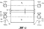
厚いストリップを製造するのに必要なロール間隙への溶融金属送給速度及び凝固速度に比べ初期間隙設定は非常に狭いので、溜めは急速に満たされ、間隙は凝固ストリップにより急速に閉じられ、大きな金属ロスを生じることなく又過剰なストリップ欠陥を生じることなく首尾一貫したストリップが直ちに確立できる。立上げ時にロール鋳造表面温度が増加するので形状が変化し、図12に示すようなほぼ平らな最終熱状態を確立する。これには45秒ほど掛かり得るが、ロール間の間隙に大いに影響を与える。しかしながら、ストリップの最終厚み、ひいてはロール間隙はロールの回転速度により決定され、動いているロールは加えられた偏寄力に対し自由に動いて、製造されたストリップ厚に順応する。従って、ロール速度は立上げ手順で変更して溜めが満たされるようにし、鋳造ストリップの所望厚を確立することができる。より明細には、ロールの回転速度は次のように制御される。
【0039】
V0 d0 < α(VpD+Δ(Q)) 式1
α > 1.0 式2
但し、
α 因子
Vp 目標製造速度
D 目標製造厚又はロール中央間隙
Δ(Q) 初期溜め充填を助けるため上流からの注湯の増分
【0040】
この式1及び2の物理的意味は
もし、α=1 で V0 d0 = α(VpD+Δ(Q)) ならば
溶湯は溜めを満たし始めることがほとんどできない。何故なら、分配器のノズルとレベルが製造流速度に合っているからである。従って、流れ速度の増分Δ(Q)は間隙を介した著しい自由落下を防ぐことができない。
【0041】
もしα=2 で V0 d0 < α(VpD+Δ(Q)) ならば、他のパラメータにもよるが、溜めは例えば5秒程で急速に満たされる。即ち、立上げ時にダミーバーを用いることなく溜めは溶湯により塞がれる。
【0042】
値VpとDは、充分な目的溜めレベルでの速度Vp及び達成厚みDでの実際の凝固を反映しているので、式1及び2の状態に従えば、αの値を充分高くとることにより、ロール間隙が最初は溶湯により、次いでは、目的の充分な溜めレベルであっても凝固殻により充填又は塞止がなされる。
【0043】
最も好ましくは、αの値は2±0.5である。
【0044】
いったん溜めが確立してストリップの全幅がd0に近い値になり、図12に示すように成長するロール熱クラウンは約30秒でほぼ平らな間隙となることができる。このため、ロールの半径方向膨張により間隙が狭くなり、従って、凝固した殻はたとえ溜めが完全に満たされる前でも、偏寄したロールを押し戻し始める。
【0045】
本発明に応じて専ら操業される特定の双ロール鋳造装置では、次のような条件が適用されている。
鋳造ロール径 500mm
鋳造ロール速度 15m/秒
熱流束 14.5Mw/m2
ストリップ厚 1.6〜1.55mm
中央でのロール間隙 1.3mm
ロールクラウン 0.25mm(負)
端でのロール間隙 0.8mm
【0046】
上記条件のもとでは、鋳造溜めが形成され、首尾一貫したストリップが確立されるのに約5秒までの時間が掛かる。
【図面の簡単な説明】
【図1】 本発明に応じて作動可能なストリップ鋳造装置の垂直断面図である。
【図2】 図1の鋳造装置の要部拡大図である。
【図3】 図1の鋳造装置の要部を示す縦断面図である。
【図4】 鋳造装置の端部立面図である。
【図5】 鋳造時にロールモジュールを除去する際の種々の状態の1つを示す図である。
【図6】 鋳造時にロールモジュールを除去する際の種々の状態の1つを示す図である。
【図7】 鋳造時にロールモジュールを除去する際の種々の状態の1つを示す図である。
【図8】 ロール偏寄ばねを組入れたロール偏寄装置の垂直断面図である。
【図9】 圧力流体アクチュエータを組入れたロール偏寄装置の垂直断面図である。
【図10】 負のクラウンを呈する2つの典型的なロール表面プロフィールを示している。
【図11】 負のクラウンを持つ2本のロールの冷間初期立上げを概略的に示している。
【図12】 同じ2本のロールの、鋳造時の熱間状態を示している。[0001]
BACKGROUND OF THE INVENTION
The present invention relates to metal strip casting by continuous casting in a twin roll casting apparatus.
[0002]
[Prior art]
In a twin roll casting apparatus, molten metal is guided between a pair of cooled horizontal casting rolls rotating in opposite directions, the metal shells are solidified on the moving roll surface, and the metal shells are united in the roll gap, This produces a solidified strip product fed downward from the roll gap between the rolls. In this specification, the term “roll gap” (nip) is used to refer to the entire region where the rolls are closest to each other. Molten metal is poured from the ladle into one or a series of small containers, and then flows to the metal supply nozzle located above the roll gap and toward the roll gap between the rolls, so that it is directly above the roll gap. A cast pool of molten metal is formed which is supported by the roll casting surface and extends in the roll gap length direction. Usually, the end of the casting pool is composed of a side plate or a side dam that is held by sliding engagement with the end surface of the roll to prevent overflow from both ends of the casting pool, but alternative means such as an electromagnetic barrier can also be used. Proposed.
[0003]
There are significant problems in starting casting in a twin roll casting machine, especially in the case of steel strip casting. It is necessary to establish a casting pool supported by a roll at the time of start-up. If steady state casting is established, the roll gap between the rolls is closed with a solidified strip, but at start-up, the molten metal can fall without proper solidification, thus making it difficult to produce a consistent strip. It becomes possible. Previously, it was thought that it was necessary to introduce a dummy bar between the casting rolls at the start-up to establish a casting pool while closing the gap between the rolls, and when the solidified strip was formed, the dummy bar had to be removed at the tip. It was. Since it was necessary to introduce a dummy bar, the initial setting procedure prior to casting was delayed, and if casting was interrupted for some reason, it was necessary to repeat this procedure and restart casting. This is particularly a problem in the case of steel casting, where the molten metal is very hot, and the refractory material of the metal delivery system must be preheated to a high temperature and assembled immediately before casting, which significantly cools the refractory material. It is necessary to pour the molten metal within a very short time before it is obtained. If the start-up procedure for starting casting with the twin roll casting apparatus can be performed without using a dummy bar, the casting can be resumed immediately after the casting is interrupted without the need for extensive resetting of the casting apparatus.
[0004]
[Problems to be solved by the invention]
Japanese Patent Application Laid-Open Nos. 59-215257 and 1-133644 each disclose a proposal in which casting in a twin roll casting apparatus can be started up without using a dummy bar. In either of these proposals, it is necessary to force gap fluctuation and corresponding roll speed control at the time of start-up, but their aim is simply to close the roll gap and establish the casting pool, so that the gap in the roll gap is established. And matching the thickness of the solidified steel shell. In the proposal disclosed in Japanese Patent Application Laid-Open No. 59-215257, the start-up starts with a small roll gap, and casting is started at a relatively high roll speed to produce a thinner strip than required. The roll speed is then reduced to force a regular increase in roll gap and to match the increase in strip thickness to the forced roll gap variation. In the proposal disclosed in JP-A-1-133644, start-up is started with a relatively wide roll gap, the flow is spread over the entire roll, then the roll gap is narrowed so that a casting pool is established, and then the roll A strip with the required thickness is produced by increasing the gap. It is extremely difficult to match the forced roll gap to the actual thickness of the solidifying metal. Furthermore, these proposals are based on the premise that the roll surface is almost parallel and the gap is uniform when starting up. However, it has been found that when casting thin steel strips, it is necessary to use a roll with a machined crown. More specifically, in order to produce a flat strip, the rolls must be machined to a negative crown, i.e. by making the diameter of the center of each roll circumference smaller than the end, It is necessary that the roll undergoes thermal expansion during casting to be substantially flat and produce a flat strip. The previous scheme, including forced gap control, generally does not allow for successful start-up with a crowned roll. The present invention provides an improved method that does not force the roll gap between the rolls during casting start-up, but responds quickly to the metal thickness cast during start-up. According to the present invention, a roll with a crown can be used, and the casting speed control for optimizing the solidified state of metal and the filling speed of the casting pool can be provided with great flexibility.
[0005]
[Means for Solving the Problems]
According to the present invention, a pair of first and second cooling cast rolls are assembled in a parallel relationship, and the first roll can be moved laterally with respect to the second roll to form a roll gap therebetween. The molten metal is poured without a dummy bar to form a molten metal casting pool supported on the peripheral surfaces of the first and second casting rolls above the roll gap, and melted in the casting pool fed downward from the roll gap. The first casting head consists of casting a strip from metal and holds the second casting roll so as not to move laterally and positions the stop means toward the second casting roll before the casting reservoir at the beginning of casting is formed. By limiting the lateral movement of the casting roll, an initial gap is set by the roll gap between the first and second casting rolls, the initial gap being smaller than the desired thickness of the strip to be continuously cast, and the shape of the casting pool. In the metal strip casting method the gap is increased for casting the desired thickness of the strip after,
At the beginning of casting, the first casting roll is continuously offset laterally toward the second casting roll, and the first and second casting rolls are solidified on the peripheral surfaces of both casting rolls to form a gap between the rolls. Producing a strip with a thickness larger than the initial gap set between the first and second casting rolls immediately at the beginning of the casting by rotating in a mutual direction at such a speed as to move towards the
Allowing the first casting roll to move laterally away from the second casting roll against continuous offset, increasing the gap at the roll gap between the rolls, thereby adapting to the initial cast strip thickness, A metal strip casting method is provided that enables continuous casting to the desired thickness .
[0006]
Preferably, by forming a roll central portion with smaller diameter than the diameter of the roll end peripheral surface, the first and second casting roll peripheral surface provided with a negative crown radially between the casting roll peripheral surface end Is set to have an interval in the range of 0.5 to 1.4 mm .
[0008]
Preferably, the negative radial crown of each roll, which is the difference in diameter between the center portion of the roll surface and the end portion, can be in the range of 0.1 to 1.5 mm.
[0011]
The biasing force can be applied to the movable roll carriage by the biasing spring.
[0012]
DETAILED DESCRIPTION OF THE INVENTION
In order that the invention may be more fully described, the operation of one particular type of casting apparatus will now be described in some detail with reference to the accompanying drawings.
[0013]
The illustrated casting apparatus is composed of a
[0014]
The
[0015]
The ladle is entirely conventional and is supported on a rotating turret from which it can be transported to a position above the
[0016]
The
[0017]
The
[0018]
The
[0019]
A pair of
[0020]
In the casting operation, the
[0021]
The
[0022]
The
[0023]
The
[0024]
Each
[0025]
The casting apparatus includes two pairs of
[0026]
A detailed configuration of the
[0027]
The
[0028]
The
[0029]
When the
[0030]
A detailed configuration of the
[0031]
In normal casting, simply applying high pressure fluid to the
[0032]
The
[0033]
According to the present invention, the central spacer or stop 107 is set prior to the casting operation so that the roll gap between the rolls at start-up is much smaller than the strip thickness to be cast. In the case of thin steel strip casting, the casting roll receives molten steel at a temperature above 1200 ° C. and thus undergoes significant thermal expansion or bulging in the cast state. Accordingly, it is machined to have a sufficiently negative crown so that it swells into a substantially parallel cylindrical shape in the cast state. This negative crown must be anticipated when setting the initial gap between rolls.
[0034]
FIG. 10 shows two typical roll profiles, both exhibiting a negative crown, with the roll end diameter being 450 microns or 0.4 mm larger than the roll center circumference. For a wide range of possible strip widths and possible roll diameters, the crown is typically 0.4 mm ± 0.3 mm. A typical roll is 500 mm in diameter and can produce a 1300 mm wide strip. The crown is significant only at the roll end and is relatively large compared to a typical cast strip thickness of 0.5-5 mm.
[0035]
FIG. 11 shows a cold roll gap initialization and thus has a negative crown c. The initial gap at the center of the roll is d 0 = 2c + g 0 where c is the radius crown of each roll and g 0 is the roll end gap. The roll end gap g 0 is a minimum value that ensures that the roll does not accidentally or unevenly contact, and a large gap d 0 at the center of the roll that prevents proper closing of the roll gap and filling control of the casting pool. Set to a maximum value that guarantees that no free fall of the molten metal can occur. In order to achieve a smooth start-up and a satisfactory reservoir fill rate for casting a strip of 0.2-0.5 mm thickness, preferably g 0 should be between 0.5-1.4 mm. It has been found that
[0036]
At start-up, the roll is rotated before pouring and then molten metal is poured into the roll gap between the rolls to establish a casting pool and form a strip. Solidified metal shells are formed on the two rolls, which are brought together in the roll gap to produce a cast strip.
[0037]
The solidification rate of the molten metal depends on the heat removal rate through the casting roll surface, and the heat removal rate depends on the roll cooling system, the cooling water flow, the texture of the casting surface, and the roll speed. The roll speed can be controlled at start-up, so that the molten metal can increase rapidly in the casting pool, but also in the present invention to produce a strip thickness that is significantly greater than the initial gap between the rolls. The biased roll then moves laterally under the influence of the corresponding biasing device (110 or 111) (either by spring bias or fluid pressure bias, depending on the mode of operation of the device). And adapt to strip formation with increased thickness.
[0038]
The initial gap setting is very narrow compared to the molten metal feed rate and solidification rate required to produce a thick strip, so the reservoir is filled quickly, and the gap is quickly closed by the solidified strip, large A consistent strip can be established immediately without any metal loss and without excessive strip defects. As the roll casting surface temperature increases during start-up, the shape changes and a substantially flat final heat state as shown in FIG. 12 is established. This can take up to 45 seconds, but it greatly affects the gap between the rolls. However, the final thickness of the strip, and thus the roll gap, is determined by the rotational speed of the roll, and the moving roll is free to move against the applied bias and adapts to the produced strip thickness. Thus, the roll speed can be changed during the start-up procedure so that the reservoir is filled and the desired thickness of the cast strip can be established. More specifically, the rotation speed of the roll is controlled as follows.
[0039]
V0 d 0 <α (VpD + Δ (Q))
α> 1.0 Equation 2
However,
α factor Vp target production rate D target production thickness or roll center gap Δ (Q) Increment of pouring from upstream to aid initial reservoir filling
The physical meaning of
[0041]
If α = 2 and V 0 d 0 <α (VpD + Δ (Q)), depending on other parameters, the reservoir is quickly filled, for example, in about 5 seconds. That is, the reservoir is closed by the molten metal without using a dummy bar at the time of start-up.
[0042]
The values Vp and D reflect the actual solidification at the velocity Vp and the achieved thickness D at a sufficient target level, so that according to the conditions of
[0043]
Most preferably, the value of α is 2 ± 0.5.
[0044]
Once the reservoir is established, the total width of the strip is close to d 0 , and the rolled thermal crown as shown in FIG. 12 can become a substantially flat gap in about 30 seconds. Because of this, the radial expansion of the rolls narrows the gap, so that the solidified shell begins to push back the offset roll even before the reservoir is completely filled.
[0045]
The following conditions are applied in a specific twin roll casting apparatus that operates exclusively according to the present invention.
Casting roll diameter 500mm
Casting roll speed 15m / sec Heat flux 14.5Mw / m 2
Strip thickness 1.6 ~ 1.55mm
Roll gap at the center 1.3mm
Roll crown 0.25mm (negative)
Roll gap at the end 0.8mm
[0046]
Under the above conditions, it takes up to about 5 seconds for the casting pool to form and to establish a consistent strip.
[Brief description of the drawings]
1 is a vertical cross-sectional view of a strip casting apparatus operable in accordance with the present invention.
FIG. 2 is an enlarged view of a main part of the casting apparatus of FIG.
3 is a longitudinal sectional view showing a main part of the casting apparatus of FIG. 1. FIG.
FIG. 4 is an end elevation view of the casting apparatus.
FIG. 5 is a diagram showing one of various states when the roll module is removed during casting.
FIG. 6 is a diagram showing one of various states when the roll module is removed during casting.
FIG. 7 is a view showing one of various states when the roll module is removed during casting.
FIG. 8 is a vertical sectional view of a roll biasing apparatus incorporating a roll biasing spring.
FIG. 9 is a vertical sectional view of a roll biasing apparatus incorporating a pressure fluid actuator.
FIG. 10 shows two typical roll surface profiles exhibiting a negative crown.
FIG. 11 schematically illustrates a cold initial start-up of two rolls with negative crowns.
FIG. 12 shows the hot state during casting of the same two rolls.
Claims (3)
鋳造手始めに、前記第1鋳造ロールを第2鋳造ロールの方へと横方向に連続偏寄させ、第1及び第2鋳造ロールを、金属殻が両鋳造ロール周面で凝固してロール間隙に向かって移動するような速度で相互方向に回転させることにより、第1及び第2鋳造ロール間で設定された初期間隙より大きな厚みのストリップを鋳造手始めに直ちに製造し、
第1鋳造ロールが連続偏寄に抗して第2鋳造ロールから横方向に離れることを許容し、ロール間のロール間隙で間隙を増加させ、それにより、初期鋳造ストリップ厚に順応させ、ストリップを前記所望厚に連続鋳造可能にする
ことを特徴とする金属ストリップ鋳造方法。A pair of first and second cooling cast rolls are assembled in a parallel relationship, the first roll can be moved laterally with respect to the second roll to form a roll gap therebetween, and a molten metal without a dummy bar To form a molten metal casting pool supported on the peripheral surfaces of the first and second casting rolls above the roll gap, and cast a strip from the molten metal in the casting pool fed downward from the roll gap. Before the casting reservoir at the beginning of casting is formed, the second casting roll is held so as not to move laterally, the stop means is positioned, and the first casting roll moves laterally toward the second casting roll. By setting the initial gap in the roll gap between the first and second casting rolls, the initial gap is smaller than the desired thickness of the strip to be continuously cast, and the strip is formed after forming the casting pool. In the metal strip casting method the gap is increased for casting the desired thickness,
At the beginning of casting, the first casting roll is continuously offset laterally toward the second casting roll, and the first and second casting rolls are solidified on the peripheral surfaces of both casting rolls to form a gap between the rolls. Producing a strip with a thickness larger than the initial gap set between the first and second casting rolls immediately at the beginning of the casting by rotating in a mutual direction at such a speed as to move towards the
Allowing the first casting roll to move laterally away from the second casting roll against continuous offset, increasing the gap at the roll gap between the rolls, thereby adapting to the initial cast strip thickness, A metal strip casting method, characterized by enabling continuous casting to the desired thickness .
Applications Claiming Priority (4)
| Application Number | Priority Date | Filing Date | Title |
|---|---|---|---|
| AUPQ2911 | 1999-09-17 | ||
| AU2911 | 1999-09-17 | ||
| AUPQ2911A AUPQ291199A0 (en) | 1999-09-17 | 1999-09-17 | Strip casting |
| PCT/AU2000/001133 WO2001021342A1 (en) | 1999-09-17 | 2000-09-18 | Strip casting |
Publications (3)
| Publication Number | Publication Date |
|---|---|
| JP2003509220A JP2003509220A (en) | 2003-03-11 |
| JP2003509220A5 JP2003509220A5 (en) | 2007-11-08 |
| JP5038569B2 true JP5038569B2 (en) | 2012-10-03 |
Family
ID=3817076
Family Applications (1)
| Application Number | Title | Priority Date | Filing Date |
|---|---|---|---|
| JP2001524754A Expired - Fee Related JP5038569B2 (en) | 1999-09-17 | 2000-09-18 | Strip casting |
Country Status (20)
| Country | Link |
|---|---|
| US (1) | US6820680B1 (en) |
| EP (1) | EP1251981B1 (en) |
| JP (1) | JP5038569B2 (en) |
| KR (1) | KR100692192B1 (en) |
| CN (1) | CN1321762C (en) |
| AR (1) | AR025676A1 (en) |
| AT (1) | ATE337118T1 (en) |
| AU (2) | AUPQ291199A0 (en) |
| BR (1) | BR0014079A (en) |
| CA (1) | CA2385229C (en) |
| CO (1) | CO5280126A1 (en) |
| DE (1) | DE60030331T2 (en) |
| ES (1) | ES2269183T3 (en) |
| MY (1) | MY123384A (en) |
| PE (1) | PE20010416A1 (en) |
| RU (1) | RU2245755C2 (en) |
| SA (1) | SA01210685B1 (en) |
| TR (1) | TR200200685T2 (en) |
| TW (1) | TW467774B (en) |
| WO (1) | WO2001021342A1 (en) |
Families Citing this family (13)
| Publication number | Priority date | Publication date | Assignee | Title |
|---|---|---|---|---|
| ITMI20021505A1 (en) * | 2002-07-10 | 2004-01-12 | Danieli Off Mecc | ROLLER SUPPORT DEVICE FOR CONTINUOUS CASTING OF METAL TAPE |
| AT411822B (en) * | 2002-09-12 | 2004-06-25 | Voest Alpine Ind Anlagen | METHOD AND DEVICE FOR STARTING A CASTING PROCESS |
| SE527507C2 (en) † | 2004-07-13 | 2006-03-28 | Abb Ab | An apparatus and method for stabilizing a metallic article as well as a use of the apparatus |
| US7556084B2 (en) * | 2006-03-24 | 2009-07-07 | Nucor Corporation | Long wear side dams |
| WO2009115877A1 (en) * | 2008-03-19 | 2009-09-24 | Nucor Corporation | Strip casting apparatus with casting roll positioning |
| US9354530B2 (en) | 2011-12-12 | 2016-05-31 | Xerox Corporation | Carboxylic acid or acid salt functionalized polyester polymers |
| CN103182492B (en) * | 2011-12-30 | 2015-12-09 | 宝山钢铁股份有限公司 | A kind of location of double-roll thin-belt continuous casting roller and roll gap adjustment method and device |
| KR101482461B1 (en) * | 2013-12-20 | 2015-01-13 | 주식회사 포스코 | Strip casting method for manufacturing austenite stainless steel having good edge porperty |
| JP5976087B2 (en) * | 2013-12-24 | 2016-08-23 | ポスコ | Damage prevention device for casting roll in thin plate manufacturing equipment. |
| US20170144218A1 (en) * | 2015-11-20 | 2017-05-25 | Nucor Corporation | Method for casting metal strip with crown control |
| US10618107B2 (en) | 2016-04-14 | 2020-04-14 | GM Global Technology Operations LLC | Variable thickness continuous casting for tailor rolling |
| CN110099763B (en) * | 2016-12-26 | 2021-03-30 | 普锐特冶金技术日本有限公司 | Twin roll type continuous casting apparatus |
| MX2019015164A (en) | 2017-06-15 | 2020-08-03 | Nucor Corp | Method for casting metal strip with edge control. |
Family Cites Families (21)
| Publication number | Priority date | Publication date | Assignee | Title |
|---|---|---|---|---|
| JPS55165260A (en) * | 1979-06-08 | 1980-12-23 | Furukawa Electric Co Ltd:The | Direct production of sheet from molten metal |
| JPS59215257A (en) * | 1983-05-20 | 1984-12-05 | Ishikawajima Harima Heavy Ind Co Ltd | Casting method in twin roll type continuous casting machine |
| DE3440236A1 (en) * | 1984-11-03 | 1986-05-22 | Mannesmann AG, 4000 Düsseldorf | METHOD AND DEVICE FOR CONTINUOUSLY CASTING METALS, ESPECIALLY STEEL |
| JPS62252642A (en) * | 1986-04-23 | 1987-11-04 | Nippon Yakin Kogyo Co Ltd | Method and apparatus for producing sheet metal directly |
| JP2684037B2 (en) * | 1987-05-22 | 1997-12-03 | 日新製鋼株式会社 | Thin plate continuous casting method |
| JPH01133644A (en) * | 1987-11-20 | 1989-05-25 | Ishikawajima Harima Heavy Ind Co Ltd | Method for starting casting in twin roll type continuous casting machine |
| JP2591098B2 (en) * | 1988-07-26 | 1997-03-19 | 石川島播磨重工業株式会社 | Twin roll continuous casting machine |
| JPH07102429B2 (en) * | 1989-05-20 | 1995-11-08 | 新日本製鐵株式会社 | Crown control method in thin casting |
| ATE153573T1 (en) * | 1990-04-04 | 1997-06-15 | Ishikawajima Harima Heavy Ind | METHOD AND DEVICE FOR CONTINUOUS STRIP CASTING |
| JP3007941B2 (en) * | 1991-11-21 | 2000-02-14 | 石川島播磨重工業株式会社 | Metal strip casting method |
| JPH05220547A (en) * | 1992-02-14 | 1993-08-31 | Nippon Steel Corp | Method for estimating plate crown in twin roll type strip continuous casting and continuous casting |
| JPH06114507A (en) * | 1992-10-09 | 1994-04-26 | Nippon Steel Corp | Brushing device for continuous casting roll |
| DE4403046C1 (en) * | 1994-01-28 | 1995-08-17 | Mannesmann Ag | Roll for a strand guide frame |
| US5477911A (en) * | 1994-03-24 | 1995-12-26 | Danieli United, Inc. | Twin roller caster |
| JP3090188B2 (en) * | 1996-06-10 | 2000-09-18 | 新日本製鐵株式会社 | Cooling drum for thin cast slab casting |
| AUPO925397A0 (en) * | 1997-09-18 | 1997-10-09 | Bhp Steel (Jla) Pty Limited | Strip casting apparatus |
| AUPO824697A0 (en) | 1997-07-25 | 1997-08-21 | Bhp Steel (Jla) Pty Limited | Strip casting |
| EP0903191B1 (en) * | 1997-09-18 | 2003-05-14 | Castrip, LLC | Strip casting apparatus |
| DE69813424T2 (en) * | 1997-09-18 | 2004-03-04 | Castrip, Llc | strip casting plant |
| CA2246900A1 (en) * | 1997-09-18 | 1999-03-18 | John Andrew Fish | Strip casting apparatus |
| DE19840898C2 (en) * | 1998-09-08 | 2000-06-29 | Thyssenkrupp Stahl Ag | Process for producing load-optimized steel strips |
-
1999
- 1999-09-17 AU AUPQ2911A patent/AUPQ291199A0/en not_active Abandoned
-
2000
- 2000-08-28 MY MYPI20003949 patent/MY123384A/en unknown
- 2000-09-12 PE PE2000000941A patent/PE20010416A1/en not_active Application Discontinuation
- 2000-09-14 CO CO00069650A patent/CO5280126A1/en active IP Right Grant
- 2000-09-15 AR ARP000104842A patent/AR025676A1/en unknown
- 2000-09-18 BR BR0014079-1A patent/BR0014079A/en not_active IP Right Cessation
- 2000-09-18 KR KR1020027003541A patent/KR100692192B1/en active IP Right Grant
- 2000-09-18 TR TR2002/00685T patent/TR200200685T2/en unknown
- 2000-09-18 WO PCT/AU2000/001133 patent/WO2001021342A1/en active IP Right Grant
- 2000-09-18 US US10/088,153 patent/US6820680B1/en not_active Expired - Lifetime
- 2000-09-18 CN CNB008129711A patent/CN1321762C/en not_active Expired - Lifetime
- 2000-09-18 RU RU2002110124/02A patent/RU2245755C2/en active
- 2000-09-18 EP EP00965628A patent/EP1251981B1/en not_active Expired - Lifetime
- 2000-09-18 JP JP2001524754A patent/JP5038569B2/en not_active Expired - Fee Related
- 2000-09-18 CA CA002385229A patent/CA2385229C/en not_active Expired - Fee Related
- 2000-09-18 DE DE60030331T patent/DE60030331T2/en not_active Expired - Lifetime
- 2000-09-18 ES ES00965628T patent/ES2269183T3/en not_active Expired - Lifetime
- 2000-09-18 AT AT00965628T patent/ATE337118T1/en active
- 2000-09-18 AU AU76311/00A patent/AU781169B2/en not_active Expired
- 2000-11-18 TW TW089119074A patent/TW467774B/en not_active IP Right Cessation
-
2001
- 2001-01-30 SA SA01210685A patent/SA01210685B1/en unknown
Also Published As
| Publication number | Publication date |
|---|---|
| AU781169B2 (en) | 2005-05-12 |
| ES2269183T3 (en) | 2007-04-01 |
| AU7631100A (en) | 2001-04-24 |
| KR20020063855A (en) | 2002-08-05 |
| EP1251981B1 (en) | 2006-08-23 |
| MY123384A (en) | 2006-05-31 |
| CO5280126A1 (en) | 2003-05-30 |
| CN1321762C (en) | 2007-06-20 |
| RU2245755C2 (en) | 2005-02-10 |
| US6820680B1 (en) | 2004-11-23 |
| KR100692192B1 (en) | 2007-03-09 |
| ATE337118T1 (en) | 2006-09-15 |
| AR025676A1 (en) | 2002-12-11 |
| CA2385229C (en) | 2009-01-20 |
| TW467774B (en) | 2001-12-11 |
| DE60030331D1 (en) | 2006-10-05 |
| JP2003509220A (en) | 2003-03-11 |
| TR200200685T2 (en) | 2002-06-21 |
| PE20010416A1 (en) | 2001-04-09 |
| CA2385229A1 (en) | 2001-03-29 |
| BR0014079A (en) | 2002-05-21 |
| EP1251981A1 (en) | 2002-10-30 |
| AUPQ291199A0 (en) | 1999-10-07 |
| DE60030331T2 (en) | 2007-08-30 |
| CN1374893A (en) | 2002-10-16 |
| SA01210685B1 (en) | 2006-12-05 |
| EP1251981A4 (en) | 2004-09-01 |
| WO2001021342A1 (en) | 2001-03-29 |
Similar Documents
| Publication | Publication Date | Title |
|---|---|---|
| US7464746B2 (en) | Method of casting thin cast strip | |
| JP5038569B2 (en) | Strip casting | |
| US6167942B1 (en) | Strip casting apparatus | |
| EP0903191B1 (en) | Strip casting apparatus | |
| US8499820B2 (en) | Strip casting apparatus with independent delivery nozzle and side dam actuators | |
| US6536506B2 (en) | Strip casting | |
| US6988530B2 (en) | Strip casting | |
| AU2001265683B8 (en) | Strip casting | |
| AU737788B2 (en) | Strip casting apparatus | |
| AU737844B2 (en) | Strip casting apparatus | |
| AU2001265683A1 (en) | Strip casting |
Legal Events
| Date | Code | Title | Description |
|---|---|---|---|
| A521 | Request for written amendment filed |
Free format text: JAPANESE INTERMEDIATE CODE: A523 Effective date: 20070803 |
|
| A621 | Written request for application examination |
Free format text: JAPANESE INTERMEDIATE CODE: A621 Effective date: 20070803 |
|
| A521 | Request for written amendment filed |
Free format text: JAPANESE INTERMEDIATE CODE: A523 Effective date: 20070803 |
|
| A977 | Report on retrieval |
Free format text: JAPANESE INTERMEDIATE CODE: A971007 Effective date: 20100720 |
|
| A131 | Notification of reasons for refusal |
Free format text: JAPANESE INTERMEDIATE CODE: A131 Effective date: 20100817 |
|
| A601 | Written request for extension of time |
Free format text: JAPANESE INTERMEDIATE CODE: A601 Effective date: 20101116 |
|
| A521 | Request for written amendment filed |
Free format text: JAPANESE INTERMEDIATE CODE: A523 Effective date: 20101117 |
|
| A602 | Written permission of extension of time |
Free format text: JAPANESE INTERMEDIATE CODE: A602 Effective date: 20101209 |
|
| A521 | Request for written amendment filed |
Free format text: JAPANESE INTERMEDIATE CODE: A523 Effective date: 20101215 |
|
| RD03 | Notification of appointment of power of attorney |
Free format text: JAPANESE INTERMEDIATE CODE: A7423 Effective date: 20110301 |
|
| A521 | Request for written amendment filed |
Free format text: JAPANESE INTERMEDIATE CODE: A523 Effective date: 20110322 |
|
| A131 | Notification of reasons for refusal |
Free format text: JAPANESE INTERMEDIATE CODE: A131 Effective date: 20110712 |
|
| A601 | Written request for extension of time |
Free format text: JAPANESE INTERMEDIATE CODE: A601 Effective date: 20111006 |
|
| A602 | Written permission of extension of time |
Free format text: JAPANESE INTERMEDIATE CODE: A602 Effective date: 20111014 |
|
| A521 | Request for written amendment filed |
Free format text: JAPANESE INTERMEDIATE CODE: A523 Effective date: 20111110 |
|
| TRDD | Decision of grant or rejection written | ||
| A01 | Written decision to grant a patent or to grant a registration (utility model) |
Free format text: JAPANESE INTERMEDIATE CODE: A01 Effective date: 20120612 |
|
| A01 | Written decision to grant a patent or to grant a registration (utility model) |
Free format text: JAPANESE INTERMEDIATE CODE: A01 |
|
| A61 | First payment of annual fees (during grant procedure) |
Free format text: JAPANESE INTERMEDIATE CODE: A61 Effective date: 20120706 |
|
| FPAY | Renewal fee payment (event date is renewal date of database) |
Free format text: PAYMENT UNTIL: 20150713 Year of fee payment: 3 |
|
| R150 | Certificate of patent or registration of utility model |
Free format text: JAPANESE INTERMEDIATE CODE: R150 |
|
| R250 | Receipt of annual fees |
Free format text: JAPANESE INTERMEDIATE CODE: R250 |
|
| R250 | Receipt of annual fees |
Free format text: JAPANESE INTERMEDIATE CODE: R250 |
|
| LAPS | Cancellation because of no payment of annual fees |